WO2017194539A1 - Appareil électroménager comprenant un bouton monté sur le panneau de commande - Google Patents
Appareil électroménager comprenant un bouton monté sur le panneau de commande Download PDFInfo
- Publication number
- WO2017194539A1 WO2017194539A1 PCT/EP2017/061057 EP2017061057W WO2017194539A1 WO 2017194539 A1 WO2017194539 A1 WO 2017194539A1 EP 2017061057 W EP2017061057 W EP 2017061057W WO 2017194539 A1 WO2017194539 A1 WO 2017194539A1
- Authority
- WO
- WIPO (PCT)
- Prior art keywords
- knob
- insert
- shaft
- control panel
- disposed
- Prior art date
- Legal status (The legal status is an assumption and is not a legal conclusion. Google has not performed a legal analysis and makes no representation as to the accuracy of the status listed.)
- Ceased
Links
Images


Classifications
-
- D—TEXTILES; PAPER
- D06—TREATMENT OF TEXTILES OR THE LIKE; LAUNDERING; FLEXIBLE MATERIALS NOT OTHERWISE PROVIDED FOR
- D06F—LAUNDERING, DRYING, IRONING, PRESSING OR FOLDING TEXTILE ARTICLES
- D06F34/00—Details of control systems for washing machines, washer-dryers or laundry dryers
- D06F34/28—Arrangements for program selection, e.g. control panels therefor; Arrangements for indicating program parameters, e.g. the selected program or its progress
- D06F34/30—Arrangements for program selection, e.g. control panels therefor; Arrangements for indicating program parameters, e.g. the selected program or its progress characterised by mechanical features, e.g. buttons or rotary dials
-
- A—HUMAN NECESSITIES
- A47—FURNITURE; DOMESTIC ARTICLES OR APPLIANCES; COFFEE MILLS; SPICE MILLS; SUCTION CLEANERS IN GENERAL
- A47L—DOMESTIC WASHING OR CLEANING; SUCTION CLEANERS IN GENERAL
- A47L15/00—Washing or rinsing machines for crockery or tableware
- A47L15/42—Details
- A47L15/4293—Arrangements for programme selection, e.g. control panels; Indication of the selected programme, programme progress or other parameters of the programme, e.g. by using display panels
-
- D—TEXTILES; PAPER
- D06—TREATMENT OF TEXTILES OR THE LIKE; LAUNDERING; FLEXIBLE MATERIALS NOT OTHERWISE PROVIDED FOR
- D06F—LAUNDERING, DRYING, IRONING, PRESSING OR FOLDING TEXTILE ARTICLES
- D06F2101/00—User input for the control of domestic laundry washing machines, washer-dryers or laundry dryers
- D06F2101/12—Washing temperature
-
- F—MECHANICAL ENGINEERING; LIGHTING; HEATING; WEAPONS; BLASTING
- F24—HEATING; RANGES; VENTILATING
- F24C—DOMESTIC STOVES OR RANGES ; DETAILS OF DOMESTIC STOVES OR RANGES, OF GENERAL APPLICATION
- F24C7/00—Stoves or ranges heated by electric energy
- F24C7/08—Arrangement or mounting of control or safety devices
Definitions
- the present invention relates to a household appliance comprising a knob that is mounted to the control panel.
- Household appliances such as laundry washing/drying machines, cooking appliances, dishwashers, etc. usually comprise a control panel whereon knobs that enable the operational status to be determined as per the preference of the users are disposed.
- the knobs are connected by means of a shaft to an encoder on a control card disposed behind the control panel by means of housings on the control panel.
- the knobs can be attached to the shaft directly or by means of an insert.
- problems due to production tolerances and displacements occurring during the assembly, deviations may occur in the position of the shaft in the housing, and in this case problems such as erroneous operation of the knob and even failure of the knob to perform its function may occur. These problems result in user dissatisfaction and a decrease in the perceived quality.
- the aim of the present invention is the realization of a household appliance comprising a knob the operational flaws of which are eliminated.
- the household appliance realized in order to attain the aim of the present invention, explicated in the claims, comprises a control panel; a control card that is positioned behind the control panel and that controls the operational status of the household appliance; a knob that is disposed on the control panel and that can be moved by the user; a housing that is disposed on the control panel and whereon the knob is placed; a shaft with one end connected to an encoder on the control card and the other end extending out of the housing, and an insert that is mounted on the shaft and that enables the knob to be connected to the shaft.
- the shaft moves together with the knob when the knob is rotated and enables the preferences received from the user by means of the knob to be transmitted to the control card.
- the household appliance of the present invention comprises the insert that has an opening wherein the shaft is housed so that the shaft slides along a linear axis, and at least one connection element that is disposed on the insert and the knob and that enables the knob to be movably connected to and engage with the insert.
- the insert can move on both the shaft and the knob and enables friction forces acting on the knob due to inclined or eccentric position of the shaft in the opening to be minimized.
- the knob is enabled to operate without any errors without being affected from erroneous positioning of the shaft.
- connection element provides the insert with the freedom of movement on the knob along an axis perpendicular to the longitudinal axis of the opening.
- eccentricity of the shaft in both horizontal and vertical directions can be tolerated.
- connection element comprises at least one extension that extends outwards from the insert perpendicularly to the sliding axis of the shaft in the opening, and at least one slit that is arranged on the knob and wherein the extensions enter when the knob is placed on the insert.
- the extensions move in the slit during the movement of the insert on the knob. Thus, the movement of the insert on the knob is guided.
- connection element comprises at least one protrusion that is disposed on the knob, and at least two extensions that are oppositely disposed on the insert and that extend outwards from the insert perpendicularly to the sliding axis of the shaft in the opening.
- the protrusion enters between the extensions and provides the insert with the freedom of movement in a single axis.
- the shaft has a D-shaped cross-section.
- the flat side of the shaft bears against the surface of the insert surrounding the opening and thus the shaft is prevented from being rotated independently of the knob.
- the knob has a wall that, when the knob is placed on the insert, extends toward the control panel so as to surround the insert, and the wall is provided with more than one claw that extends outwards from the edge of the wall perpendicularly to the wall.
- the knob is fixed on the control panel by passing the claws through the housing so that the claws contact the control panel from the rear side thereof. Thus, the knob is prevented from detaching from the control panel.
- the knob is enabled to perform its function without any errors in the cases where the shaft is not positioned properly in the opening due to production tolerances and any displacement occurring during the assembly. Moreover, by means of the present invention, the knob is prevented from inclining during the operation in the case when the shaft is mounted in an inclined manner.
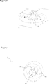
- Figure 1 - is the view of the control panel and the knob related to an embodiment of the present invention.
- Figure 2 - is the partial perspective view of the control panel and the knob related to an embodiment of the present invention.
- Figure 3 — is the perspective view of the shaft and the insert related to an embodiment of the present invention.
- Figure 4 – is the rear perspective view of the knob related to an embodiment of the present invention.
- Figure 5 — is the partial schematic view of the knob, the shaft and the insert related to an embodiment of the present invention.
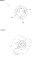
- Figure 6 — is the perspective view of the shaft and the insert related to another embodiment of the present invention.
- Figure 7 — is the rear perspective view of the know related to another embodiment of the present invention.
- Figure 8 — is the partial perspective view of the control panel, the knob, the shaft and the insert related to another embodiment of the present invention.
- the household appliance (1) comprises a control panel (2); a control card (3) that is disposed behind the control panel (2); an encoder (4) that enables the settings determined by the user to be transmitted to the control card (3); a shaft (5) that is connected to the encoder (4); a housing (6) that enables the shaft (5) to extend outwards from the control panel (2); a knob (7) that is disposed on the control panel (2) and that actuates the shaft (5), and an insert (8) that is disposed between the shaft (5) and the knob (7).
- the shaft (5) that is connected by means of the insert (8) to the knob (7) also moves, and the encoder (4) disposed at the other end of the shaft (5) enables the user preferences such as washing program, washing temperature, etc. located at predetermined positions to be transmitted to the control card (3).
- the household appliance (1) of the present invention comprises a longitudinal opening (9) that is arranged on the insert (8), through which the shaft (5) passes and that enables the insert (8) to move on the shaft (5) perpendicularly to the axis of the shaft (5), and at least one connection element (10) that is disposed on the insert (8) and the knob (7) and that enables, when the knob (7) is placed on the insert (8), the insert (8) to be movably connected to and engage with the knob (7).
- the insert (8) is placed on the shaft (5) by passing the end of the shaft (5) extending outwards from the housing (6) through the opening (9).
- the opening (9) has a longitudinal form so as to provide the shaft (5) with freedom of movement perpendicularly to the axis of the shaft (5).
- the knob (7) is connected to the insert (8) by means of the connection element (10), and the connection element (10) enables the insert (8) to move on the knob (7).
- the insert (8) moves by sliding on both the shaft (5) and the knob (7) while the knob (7) is rotated and enables the effects of any assembly defects of the shaft (5) on the movement of the knob (7) to be eliminated.
- the knob (7) is enabled to be always rotated in full circle.
- connection element (10) enables the insert (8) to move on the knob (7) perpendicularly to the movement direction of the shaft (5) in the opening (9).
- the insert (8) can move on the knob (7) along an axis perpendicular to the longitudinal axis of the opening (9).
- the insert (8) can move along both horizontal and vertical axes.
- the insert (8) comprises at least one extension (11) that is disposed thereon and that extends outwards from the insert (8) perpendicularly to the longitudinal axis of the opening (9), and the knob (7) comprises at least one slit (12) wherein the extension (11) enters when the knob (7) is placed on the insert (8), that guides the movement of the insert (8) that is perpendicular to the movement of the shaft (5) in the opening (9).
- Two extensions (11) that extend in opposite directions are provided on the insert (8).
- the knob (7) is placed on the insert (8) by fitting the extensions (11) into the slits (12). In the position where the longitudinal axis of the opening (8) is horizontal, the extensions (11) extend on the vertical axis.
- eccentricity of the shaft (5) in the horizontal axis is compensated by the shaft (5) sliding to left or right in the opening (9), and in the case that the shaft (5) is in a position that is lower or higher than the correct position, the eccentricity of the shaft (5) in the vertical axis can be tolerated by means of the movement of the insert (8) on the knob (7) in vertical direction.
- the shaft (5) moves in the opening (9) and pushes the insert (8) so as to enable the extensions (11) to move in the slits (12).
- the longitudinal axis of the opening (9) extends in the vertical direction so as to correct the positioning error of the shaft (5) in the vertical direction and the slits (12) enable the insert (8) to move to left and right on the knob (7) so as to tolerate the eccentricity of the shaft (5) in the horizontal axis.
- the insert (8) comprises at least one pair of extensions (11) that are oppositely disposed thereon and that extend outwards from the insert (8) perpendicularly to the longitudinal axis of the opening (9), and the knob (7) comprises at least one protrusion (13) that enters between the extensions (11) when the knob (7) is placed on the insert (8).
- Two pairs of extensions (11) are disposed on the insert (8) so as to be symmetrical with respect to the longitudinal axis of the opening (9).
- Two protrusions (13) are oppositely disposed on the surface of the knob (7) facing the control panel (2) and the protrusions (13) are seated between the extensions (11) when the knob (7) is placed on the insert (8).
- the protrusions (13) limit the movement of the insert (8) and enable the same to move in a single axis on the knob (7).
- the insert (8) is pushed by the shaft (5) while the knob (7) is rotated, and the extensions (11) move perpendicularly to the longitudinal axis of the opening (9) so as to slide over the protrusions (13).
- the shaft (5) has at least one flat surface that bears against the insert (8) so as to prevent the shaft (5) from rotating in the opening (9).
- the flat surface of the shaft (5) bears against the wall of the insert (8) that surrounds the opening (9) and thus the shaft (5) is prevented from rotating independently of the insert (8).
- the knob (7) has at least one wall (14) that extends toward the control panel (2), and the wall (14) is provided with at least one claw (15) that extends outwards from the edge of the wall (14) and that, when passed through the housing (6), bears against the rear surface of the control panel (2) so as to enable the knob (7) to be fixed on the control panel (2).
- the wall (14) extends toward the control panel (2) from the side of the knob (7) facing the control panel (2) so as to surround the insert (8) when the knob (7) is placed on the insert (8).
- the claws (15) each extend outwards from the edge of the wall (14) in a different direction so as to be perpendicular to the wall (14). When passed through housing (6), the claws (15) bear against the control panel (2) from the rear side thereof and prevent the knob (7) from detaching from the control panel (2).
- the household appliance (1) is a laundry washing and/or drying machine.
- any operational defects such as the knob (7) inclining, getting stuck, rubbing or rotating eccentrically with respect to the center of the slot (6) due to erroneous assembly of the shaft (5), that cause a decrease in the quality perception of the users, are eliminated.
- the production costs of the components are reduced and the quantity of scrap is reduced.
Landscapes
- Engineering & Computer Science (AREA)
- Textile Engineering (AREA)
- Mechanical Control Devices (AREA)
Abstract
La présente invention concerne un appareil électroménager (1) comprenant un panneau de commande (2) ; une carte de commande (3) qui est placée derrière le panneau de commande (2) ; un codeur (4) qui permet aux réglages déterminés par l'utilisateur d'être transmis à la carte de commande (3) ; un arbre (5) qui est relié au codeur (4) ; un boîtier (6) qui permet à l'arbre (5) de s'étendre vers l'extérieur à partir du panneau de commande (2) ; un bouton (7) qui est placé sur le panneau de commande (2) et qui actionne l'arbre (5), et un insert (8) qui est placé entre l'arbre (5) et le bouton (7), une ouverture longitudinale (9) étant disposée sur l'insert (8), à travers laquelle passe l'arbre (5) et qui permet à l'insert (8) de se déplacer sur l'arbre (5) perpendiculairement à l'axe de l'arbre (5), et au moins un élément de liaison (10) qui est placé sur l'insert (8) et le bouton (7) et qui permet à l'insert (8), lorsque le bouton (7) est situé sur l'insert (8), d'être relié de manière mobile au bouton (7) et de venir en prise avec ce dernier.
Applications Claiming Priority (2)
| Application Number | Priority Date | Filing Date | Title |
|---|---|---|---|
| TRA2016/06171 | 2016-05-10 | ||
| TR201606171 | 2016-05-10 |
Publications (1)
| Publication Number | Publication Date |
|---|---|
| WO2017194539A1 true WO2017194539A1 (fr) | 2017-11-16 |
Family
ID=58772856
Family Applications (1)
| Application Number | Title | Priority Date | Filing Date |
|---|---|---|---|
| PCT/EP2017/061057 Ceased WO2017194539A1 (fr) | 2016-05-10 | 2017-05-09 | Appareil électroménager comprenant un bouton monté sur le panneau de commande |
Country Status (1)
| Country | Link |
|---|---|
| WO (1) | WO2017194539A1 (fr) |
Citations (5)
| Publication number | Priority date | Publication date | Assignee | Title |
|---|---|---|---|---|
| FR2708061A1 (fr) * | 1993-07-23 | 1995-01-27 | Cepem | Système d'accouplement à rattrapage de jeu entre deux pièces d'axes parallèles. |
| DE19943902A1 (de) * | 1998-10-02 | 2000-04-20 | Valeo Electronique Creteil | Kupplungsvorrichtung zwischen einem Bedienknopf und einem Mechanismus |
| WO2000046822A1 (fr) | 1999-02-08 | 2000-08-10 | Arçelik A.Ş. | Ensemble bouton-poussoir elliptique |
| US20030221498A1 (en) * | 2002-05-30 | 2003-12-04 | Shadi Mere | Control knob to position encoder interface with self-aligning rotary guide |
| WO2008074706A1 (fr) * | 2006-12-18 | 2008-06-26 | Arcelik Anonim Sirketi | Appareil électroménager |
-
2017
- 2017-05-09 WO PCT/EP2017/061057 patent/WO2017194539A1/fr not_active Ceased
Patent Citations (5)
| Publication number | Priority date | Publication date | Assignee | Title |
|---|---|---|---|---|
| FR2708061A1 (fr) * | 1993-07-23 | 1995-01-27 | Cepem | Système d'accouplement à rattrapage de jeu entre deux pièces d'axes parallèles. |
| DE19943902A1 (de) * | 1998-10-02 | 2000-04-20 | Valeo Electronique Creteil | Kupplungsvorrichtung zwischen einem Bedienknopf und einem Mechanismus |
| WO2000046822A1 (fr) | 1999-02-08 | 2000-08-10 | Arçelik A.Ş. | Ensemble bouton-poussoir elliptique |
| US20030221498A1 (en) * | 2002-05-30 | 2003-12-04 | Shadi Mere | Control knob to position encoder interface with self-aligning rotary guide |
| WO2008074706A1 (fr) * | 2006-12-18 | 2008-06-26 | Arcelik Anonim Sirketi | Appareil électroménager |
Similar Documents
| Publication | Publication Date | Title |
|---|---|---|
| US9255355B2 (en) | Control-panel assembly for household appliances and household appliance provided with such control-panel assembly | |
| CN209215975U (zh) | 包括旋钮装置的电器设备 | |
| GB2130438A (en) | Rotary knob | |
| EP2837721B1 (fr) | Appareil de lavage du linge fourni avec un ensemble de panneau de commande | |
| EP2773804B1 (fr) | Appareil électroménager comprenant un bouton à touche | |
| US9777421B2 (en) | Control panel and clothes treating apparatus having the same | |
| WO2017194539A1 (fr) | Appareil électroménager comprenant un bouton monté sur le panneau de commande | |
| WO2013098243A2 (fr) | Appareil électroménager | |
| US9800241B2 (en) | Household appliance comprising a touch button | |
| EP4187009A1 (fr) | Appareil électroménager comprenant un bouton | |
| EP2764524B1 (fr) | Appareil électroménager | |
| EP3447182B1 (fr) | Appareil ménager et procédé de fonctionnement associé | |
| WO2016134933A1 (fr) | Appareil électroménager comportant un dispositif de connexion pour alimentation sur secteur et transmission de données | |
| WO2020126468A1 (fr) | Appareil électroménager comprenant un élément décoratif pouvant être attaché/détaché par rapport au bouton | |
| EP3139394B1 (fr) | Appareil électroménager comprenant un bouton monté solidement sur le panneau | |
| EP4202104A1 (fr) | Machine à laver | |
| WO2017194500A2 (fr) | Appareil électroménager comprenant un bouton fermement monté sur le panneau | |
| CN222823542U (zh) | 转轴组件、旋转屏幕、门体和洗碗机 | |
| WO2007013023A2 (fr) | Appareil electromenager | |
| EP3334320B1 (fr) | Appareil électroménager comprenant un bouton monté sur le panneau de commande | |
| WO2017134222A1 (fr) | Appareil électroménager comprenant un bouton transparent | |
| EP3063599A1 (fr) | Appareil électroménager pourvu d'un bouton | |
| WO2017108358A1 (fr) | Machine à laver | |
| KR20060085808A (ko) | 드럼세탁기 컨트롤패널 어셈블리의 버튼 조립구조 | |
| TR2023001344A2 (tr) | Beyaz eşyalar için bir kontrol düğmesi. |
Legal Events
| Date | Code | Title | Description |
|---|---|---|---|
| NENP | Non-entry into the national phase |
Ref country code: DE |
|
| 121 | Ep: the epo has been informed by wipo that ep was designated in this application |
Ref document number: 17725892 Country of ref document: EP Kind code of ref document: A1 |
|
| 122 | Ep: pct application non-entry in european phase |
Ref document number: 17725892 Country of ref document: EP Kind code of ref document: A1 |