WO2017195571A1 - バッグ及びファスナー - Google Patents
バッグ及びファスナー Download PDFInfo
- Publication number
- WO2017195571A1 WO2017195571A1 PCT/JP2017/016011 JP2017016011W WO2017195571A1 WO 2017195571 A1 WO2017195571 A1 WO 2017195571A1 JP 2017016011 W JP2017016011 W JP 2017016011W WO 2017195571 A1 WO2017195571 A1 WO 2017195571A1
- Authority
- WO
- WIPO (PCT)
- Prior art keywords
- bag
- bag body
- deformation
- shape maintaining
- opening
- Prior art date
- Legal status (The legal status is an assumption and is not a legal conclusion. Google has not performed a legal analysis and makes no representation as to the accuracy of the status listed.)
- Ceased
Links
Images


Classifications
-
- A—HUMAN NECESSITIES
- A45—HAND OR TRAVELLING ARTICLES
- A45C—PURSES; LUGGAGE; HAND CARRIED BAGS
- A45C9/00—Purses, Luggage or bags convertible into objects for other use
-
- A—HUMAN NECESSITIES
- A45—HAND OR TRAVELLING ARTICLES
- A45C—PURSES; LUGGAGE; HAND CARRIED BAGS
- A45C3/00—Flexible luggage; Handbags
-
- A—HUMAN NECESSITIES
- A45—HAND OR TRAVELLING ARTICLES
- A45C—PURSES; LUGGAGE; HAND CARRIED BAGS
- A45C11/00—Receptacles for purposes not provided for in groups A45C1/00-A45C9/00
-
- A—HUMAN NECESSITIES
- A45—HAND OR TRAVELLING ARTICLES
- A45C—PURSES; LUGGAGE; HAND CARRIED BAGS
- A45C13/00—Details; Accessories
- A45C13/10—Arrangement of fasteners
- A45C13/1023—Arrangement of fasteners with elongated profiles fastened by sliders
- A45C13/103—Arrangement of zip-fasteners
-
- A—HUMAN NECESSITIES
- A45—HAND OR TRAVELLING ARTICLES
- A45C—PURSES; LUGGAGE; HAND CARRIED BAGS
- A45C13/00—Details; Accessories
- A45C13/10—Arrangement of fasteners
- A45C13/1038—Arrangement of fasteners of flexible ties
-
- A—HUMAN NECESSITIES
- A45—HAND OR TRAVELLING ARTICLES
- A45C—PURSES; LUGGAGE; HAND CARRIED BAGS
- A45C13/00—Details; Accessories
- A45C13/10—Arrangement of fasteners
- A45C13/1076—Arrangement of fasteners with a snap action
- A45C13/1092—Arrangement of fasteners with a snap action of the socket-and-pin type
-
- A—HUMAN NECESSITIES
- A45—HAND OR TRAVELLING ARTICLES
- A45C—PURSES; LUGGAGE; HAND CARRIED BAGS
- A45C7/00—Collapsible or extensible purses, luggage, bags or the like
- A45C7/0059—Flexible luggage; Hand bags
- A45C7/0063—Flexible luggage; Hand bags comprising an integrated expansion device
- A45C7/0068—Flexible luggage; Hand bags comprising an integrated expansion device with slide fastener strips
-
- A—HUMAN NECESSITIES
- A44—HABERDASHERY; JEWELLERY
- A44B—BUTTONS, PINS, BUCKLES, SLIDE FASTENERS, OR THE LIKE
- A44B19/00—Slide fasteners
- A44B19/02—Slide fasteners with a series of separate interlocking members secured to each stringer tape
- A44B19/04—Stringers arranged edge-to-edge when fastened, e.g. abutting stringers
- A44B19/06—Stringers arranged edge-to-edge when fastened, e.g. abutting stringers with substantially rectangular members having interlocking projections and pieces
-
- A—HUMAN NECESSITIES
- A45—HAND OR TRAVELLING ARTICLES
- A45C—PURSES; LUGGAGE; HAND CARRIED BAGS
- A45C11/00—Receptacles for purposes not provided for in groups A45C1/00-A45C9/00
- A45C11/001—Receptacles for purposes not provided for in groups A45C1/00-A45C9/00 for storing portable audio devices, e.g. headphones or digital music players
-
- A—HUMAN NECESSITIES
- A45—HAND OR TRAVELLING ARTICLES
- A45C—PURSES; LUGGAGE; HAND CARRIED BAGS
- A45C2200/00—Details not otherwise provided for in A45C
- A45C2200/15—Articles convertible into a stand, e.g. for displaying purposes
Definitions
- the present invention relates to a bag and a fastener.
- the present invention has been made in view of such circumstances, and provides a technique that makes it possible to easily construct a headphone stand in a cafe or the like.
- a bag body having a front surface portion and a back surface portion facing each other, an opening portion provided on the upper side of the bag body, and closing the opening portion and inflating the bag body A shape maintaining portion is provided.
- the present inventor conducted an intensive study to construct a headphone stand with a familiar one, and focused on a bag that accommodates and carries the headphones, and a shape maintaining portion that maintains the bag body of the bag in an inflated state.
- the bag can be turned upside down and placed stably.
- the bag turned upside down can be suitably used as a headphone stand.
- such an upside-down bag can be used as a mounting table for mounting other items, or it can be used as an electronic device by incorporating functional parts such as speakers on the side.
- the present invention has been completed.
- the bag of the present invention is a compact bag body in a normal state, but by maintaining the bag body in an inflated state by the shape maintaining portion, the bag can be turned upside down to exhibit a desired function. Can do.
- the shape maintaining part includes a pair of connecting parts which are provided adjacent to both ends of the bag body and can be connected to each other.
- the pair of connecting portions is a pair of engaging portions that can be engaged with each other.
- the opening is provided with a fastener, and the pair of connecting portions are provided at both ends of the fastener.
- the shape maintaining part includes an internal support member that is provided inside the bag body and prevents the front part and the back part from approaching each other.
- the shape maintaining portion includes a surface shape maintaining member provided on at least one of the front surface portion and the back surface portion, and the surface shape maintaining member is deformed on a surface provided with the surface shape maintaining member. It is configured to maintain its shape when Preferably, on the lower side of the bag body, a deformation inducing portion that is convex from the side surface of the bag body toward the center side of the bag body is provided, and the deformation inducing portion induces deformation of the bag body, A mounting surface is formed around the deformation inducing portion.
- the fastener which has the connection part which can mutually be connected is provided at both ends.
- FIG. 1 It is a front view of bag 100 concerning a 1st embodiment of the present invention. It is a rear view of the bag 100 which concerns on 1st Embodiment of this invention. It is a figure showing the two connection parts corresponded to the shape maintenance part concerning a 1st embodiment of the present invention, (a) shows connection part 5, and (b) shows connection part 6.
- FIG. It is a figure showing the state to which the connection parts 5 and 6 were attached. It is a figure showing the state in which the bag 100 deform
- FIG 3 is a diagram illustrating a state in which an object is placed on the placement surface 10.
- a mode that the headphones 20 were mounted in the mounting surface 10 is shown.
- the string member 30 is attached to two string member attachment rings 8 provided in the bag 100.
- 2nd Embodiment of this invention is shown.
- an example of an internal support member 70 that supports the front portion 1 and the back portion 2 of the bag 100 from the inside is shown.
- a bag 100 according to a first embodiment of the present invention will be described with reference to FIGS.
- the bag 100 prevents the bag body including the front surface portion 1 shown in FIG. 1 and the back surface portion 2 shown in FIG. 2, the opening portion 3 provided on the upper side of the bag body shown in FIG. And a shape maintaining section that maintains the bag body in an inflated state.
- the shape maintaining portion is configured by connecting portions 5 and 6 that are provided at both ends of the fastener 4 and can be connected to each other.
- the bag body has a two-layer structure, the outside is a leather bag body, and a felt bag body is formed inside the leather bag body.
- these materials are arbitrary, and can be formed of any material depending on the application.
- the upper part of the front part 1 and the back part 2 is formed with the felt 9 for aesthetic improvement.
- a fastener 4 is provided along the longitudinal direction of the opening 3. And the thing can be accommodated in the inside of a bag body by making the opening part 3 into an open state.
- the fastener 4 includes a slider 41, a tape 42, and an element 43.
- the slider 41 has a function of engaging the element 43, and the opening / closing state of the opening 3 can be changed by moving the slider 41.
- the tape 42 is a portion where the element 43 is provided.
- the element 43 meshes with the slider 41 and enables the slider 41 to move. And the opening part 3 will be in a closed state by the element 43 engaging and closing.
- Both ends of the fastener 4 are adjacent to both ends in the longitudinal direction of the opening 3, and connecting portions 5 and 6 are provided at both ends of the fastener 4.
- the connecting portions 5 and 6 can be connected to each other. By connecting the connecting portions 5 and 6 to each other, both ends in the longitudinal direction of the opening portion 3 approach each other.
- the connecting portion 5 includes an engaging portion 51 and a notch portion 52. Further, the connecting portion 6 is provided with an opening 61. Then, as shown in FIG. 4, the engaging portion 51 is inserted into the opening 61 and rotated approximately 90 degrees, whereby the T-shaped portion of the engaging portion 51 is caught on both sides of the opening 61, and the connecting portions 5, 5 are connected. 6 is attached. Thus, the connection parts 5 and 6 become a structure which can be mutually connected by engagement. By connecting the connection parts 5 and 6, the bag body is maintained in an inflated state. That is, the fastener 4 can be said to be a fastener having connecting portions (connecting portions 5 and 6) that can be connected to each other at both ends.
- a deformation inducing portion 7 (see FIG. 1) that protrudes from the side surface of the bag body toward the center side of the bag body on the lower side of the front surface portion 1 and the back surface portion 2 constituting the bag body.
- the deformation induction part 7 is a seam, and the front part 1 and the back part 2 can be bent along the deformation induction part 7 toward the inside of the bag body.
- the felt bag inside the bag does not exist in a triangular region constituted by the deformation inducing part 7, the front part 1, and the back part 2. This is because there is no felt bag in such a triangular region, so that the front portion 1 and the back portion 2 can be easily bent toward the inside of the bag.
- the front surface portion 1 and the back surface portion 2 are bent toward the inside of the bag body along the deformation inducing portion 7, and the bag 100 is turned upside down, as shown in FIG. It will be in a state to be.
- the bag 100 can be independent on the table or the floor by preventing the opening 3 from being closed by the connecting portions 5 and 6 and maintaining the bag 100 in an inflated state.
- the mounting surface 10 is formed in the periphery of the deformation
- FIG. 6 is a diagram illustrating a usage example of the bag 100 in the state of FIG.
- a state in which the headphones 20 are placed on the placement surface 10 is shown, but what is placed on the placement surface 10 is not limited to this.
- a string member attaching ring 8 is provided in the vicinity of the boundary between the front surface portion 1 and the back surface portion 2 with the felt 9. If necessary, both ends of the string member 30 may be attached to the bag 100 via the string member attachment ring 8 as shown in FIG.
- the bag 100 is made to stand on the table with the bag 100 turned upside down, and an object is placed on the placement surface 10 formed by the deformation inducing part 7. Is possible. This makes it possible to secure a place for placing an object such as the headphones 20 even on a narrow table such as a cafe.
- connection parts 5 and 6 have another structure (Example: button, eyelet, surface) You may connect with a fastener and a string.
- connection parts 5 and 6 were connected by engaging with each other, the connection parts 5 and 6 may be connected with each other by magnetic force or adhesive force.
- fastener 4 is provided in the opening part 3, the fastener 4 is omissible.
- connection parts 5 and 6 can be arrange
- the connecting portions 5 and 6 may be provided inside the bag body. And it will be in the state shown in Drawing 8 (b) by connecting connecting parts 5 and 6 mutually.
- the bag body which has the front part and back part which oppose each other was demonstrated, it is applicable also to the bag of a shape which cannot distinguish a front part and a back part clearly. In such a case, a part of the bag is regarded as the front part, and a portion facing the front part is regarded as the back part.
- an internal support member 70 is provided inside the bag body, and the internal support member 70 constitutes a shape maintaining portion.
- the internal support member 70 prevents the front surface portion 1 and the back surface portion 2 from approaching each other, so that the bag body is maintained in an inflated state.
- the internal support member 70 may be placed in a pocket or the like inside the bag 100 when the bag 100 is not deformed. Moreover, you may fix the part to the inner surface (for example, the part shown by the area
- the inner support member 70 can have any shape that can prevent the front portion 1 and the back portion 2 from approaching each other, and may have a rod shape as shown in FIG. 9 or another shape such as a circle. May be.
- the front surface portion 1 and the back surface portion 2 constituting the bag body are provided with a surface shape maintaining member that maintains the shape when the front surface portion 1 or the back surface portion 2 is deformed.
- a shape maintenance part is comprised by the member.
- the surface shape maintaining member is formed of a member that can be easily plastically deformed, such as a thin metal plate. When such a member is built in the front part 1 and the back part 2 or attached to the surface thereof, the front part 1 and the back part 2 are deformed so that the bag body is inflated, so that the surface shape is maintained.
- the shape of the front part 1 and the back part 2 is maintained by the member.
- the surface shape maintaining member is preferably provided on both the front surface portion 1 and the back surface portion 2, but may be provided on only one side.
- the bag 100 is used as a headphone stand.
- the method of using the bag 100 is not limited thereto.
- an electronic device such as a speaker
- a pattern or an illustration can be attached and used as an object in a state where the bag 100 is deformed (that is, a state in which the bag 100 is upside down from the normal state).
Landscapes
- Purses, Travelling Bags, Baskets, Or Suitcases (AREA)
Abstract
カフェなどにおいてヘッドフォンスタンドを簡易に構築することを可能にする技術を提供する。 本発明によれば、互いに対向する前面部と背面部を有する袋体と、前記袋体の上辺に設けられた開口部と、前記開口部の閉口を阻止し且つ前記袋体を膨らんだ状態に維持する形状維持部と、を有するバッグが提供される。
Description
本発明は、バッグ及びファスナーに関する。
近年、ヘッドフォンの愛用者が増えている。家庭においては、ヘッドフォンを使用しないときには、特許文献1に開示されているようなヘッドフォンスタンドに掛けて保持することが一般的である。
ところで、ヘッドフォンの愛用者は、カフェなどにおいてもヘッドフォンを利用することが多いが、カフェにはヘッドフォンスタンドがないので、席を外すときにヘッドフォンを置く場所がなく困ることが多い。
本発明はこのような事情に鑑みてなされたものであり、カフェなどにおいてヘッドフォンスタンドを簡易に構築することを可能にする技術を提供するものである。
本発明によれば、互いに対向する前面部と背面部を有する袋体と、前記袋体の上辺に設けられた開口部と、前記開口部の閉口を阻止し且つ前記袋体を膨らんだ状態に維持する形状維持部と、を有するバッグが提供される。
本発明者は、身近にあるものでヘッドフォンスタンドを構築すべく鋭意検討を行ったところ、ヘッドフォンを収容して持ち運ぶバッグに注目し、このバッグの袋体を膨らんだ状態に維持する形状維持部を設けることによって、バッグを裏返しにして安定して立てることができることに気がついた。そして、裏返して立てたバッグがヘッドフォンスタンドとして好適に利用可能であることに気がついた。また、このような裏返して立てたバッグは、ヘッドフォンスタンド以外にも、別のものを載置する載置台として利用可能であったり、側面にスピーカーなどの機能部品を組み込むことによって電子機器として利用可能であったりすることに気が付き、本発明の完成に到った。
このように、本発明のバッグは、通常の状態では、コンパクトな袋体でありながら、形状維持部によって袋体を膨らんだ状態に維持することにより、裏返して立てて所望の機能を発揮させることができる。
このように、本発明のバッグは、通常の状態では、コンパクトな袋体でありながら、形状維持部によって袋体を膨らんだ状態に維持することにより、裏返して立てて所望の機能を発揮させることができる。
ここで、本発明の種々の実施形態を例示する。これらの実施形態は、互いに組み合わせ可能である。
好ましくは、前記形状維持部は、前記袋体の両端に隣接して設けられ且つ互いに連結可能な一対の連結部を備える。
好ましくは、前記一対の連結部は、互いに係合可能な一対の係合部である。
好ましくは、前記開口部にはファスナーが設けられ、前記一対の連結部は、前記ファスナーの両端に設けられる。
好ましくは、前記形状維持部は、前記袋体内部に設けられ且つ前記前面部と前記背面部が近接することを阻止する内部支持部材を備える。
好ましくは、前記形状維持部は、前記前面部及び前記背面部の少なくとも一方に設けられた面形状維持部材を備え、前記面形状維持部材は、前記面形状維持部材が設けられた面が変形されたときにその形状を維持するように構成される。
好ましくは、前記袋体の下辺側に、前記袋体の側面から前記袋体の中央側に向かって凸となる変形誘発部が設けられ、前記変形誘発部により前記袋体の変形が誘発され、前記変形誘発部周辺に載置面が形成されるように構成される。
好ましくは、袋体と、前記袋体の上辺に設けられた開口部を備え、前記袋体の下辺側に、前記袋体の側面から前記袋体の中央側に向かって凸となる変形誘発部が設けられ、前記変形誘発部により前記袋体の変形が誘発され、前記変形誘発部周辺に載置面が形成されるように構成される、バッグが提供される。
好ましくは、互いに連結可能な連結部を両端に有するファスナーが提供される。
以下、本発明の実施形態について説明する。以下の実施形態は、例示であって、本発明の範囲は、以下の実施形態で示すものに限定されない。
1.第1実施形態
図1~図7を用いて、本発明の第1実施形態に係るバッグ100について説明する。バッグ100は、図1に示す前面部1と図2に示す背面部2からなる袋体と、図4に示す袋体の上辺に設けられた開口部3と、開口部3の閉口を阻止し且つ袋体を膨らんだ状態に維持する形状維持部と、を有する。ここで、図3に示されるように、本実施形態では、形状維持部は、ファスナー4の両端に設けられ且つ互いに連結可能な連結部5,6によって構成される。
図1~図7を用いて、本発明の第1実施形態に係るバッグ100について説明する。バッグ100は、図1に示す前面部1と図2に示す背面部2からなる袋体と、図4に示す袋体の上辺に設けられた開口部3と、開口部3の閉口を阻止し且つ袋体を膨らんだ状態に維持する形状維持部と、を有する。ここで、図3に示されるように、本実施形態では、形状維持部は、ファスナー4の両端に設けられ且つ互いに連結可能な連結部5,6によって構成される。
本実施形態では、袋体は2層構造であり、外部はレザー製の袋体であり、レザー製の袋体の内部にフェルト製の袋体が形成されている。なお、これらの素材は任意であり、用途に応じて任意の素材で形成することができる。さらに、本実施形態では、美観向上のため、前面部1及び背面部2の上部はフェルト9で形成される。
開口部3の長手方向に沿って、ファスナー4が設けられる。そして、開口部3を開口状態として、袋体の内部に物を収納することができる。ここで、ファスナー4は、スライダー41、テープ42及びエレメント43により構成される。スライダー41は、エレメント43を噛みあわせる機能を有し、スライダー41を移動させることにより開口部3の開閉状態を変化させることができる。テープ42は、エレメント43が設けられる部分である。エレメント43は、スライダー41と噛み合い、スライダー41の移動を可能とするものである。そして、エレメント43が噛みあって閉じることにより、開口部3が閉状態となる。
ファスナー4の両端は、開口部3の長手方向の両端に隣接しており、ファスナー4の両端に連結部5,6が設けられる。連結部5,6は、互いに連結可能であり、連結部5,6を互いに連結させることにより、開口部3の長手方向の両端が互いに接近する。
図3に示されるように、本実施形態では、連結部5は係合部51及び切欠部52を備える。また、連結部6には、開口61が設けられる。そして、図4に示されるように、係合部51を開口61に挿入し、略90度回転させることにより、係合部51のT字部分が開口61の両側辺に引っ掛かり、連結部5,6が取り付けられる。このように、連結部5,6は、係合によって互いに連結可能な構成になっている。連結部5,6を連結させることにより、袋体が膨らんだ状態に維持される。つまり、ファスナー4は、互いに連結可能な連結部(連結部5,6)を両端に有する有するファスナーであると言える。
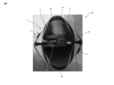
図1及び図2に示されるように、袋体を構成する前面部1及び背面部2の下辺側に、袋体の側面から袋体の中央側に向かって凸となる変形誘発部7(図中の白破線。以下同様。)が設けられる。本実施形態では、変形誘発部7は縫目であり、変形誘発部7に沿って前面部1及び背面部2を袋体の内部に向けて折り曲げることが可能になっている。ここで、袋体内部のフェルト製の袋体は、変形誘発部7と前面部1及び背面部2で構成される三角形の領域には存在しないような形状であることが好ましい。これは、かかる三角形の領域にフェルト製の袋体が存在しないことにより、容易に前面部1及び背面部2を袋体の内部に向けて折り曲げることが可能となるためである。
そして、連結部5,6を取り付けた状態で、変形誘発部7に沿って前面部1及び背面部2を袋体の内部に向けて折り曲げ、バッグ100の上下を逆にすると、図5に示される状態となる。バッグ100は、連結部5,6により開口部3の閉口が阻止され且つバッグ100が膨らんだ状態に維持されることにより、テーブルや床上で自立することが可能となる。そして、変形誘発部7に沿って前面部1及び背面部2を袋体の内部に向けて折り曲げることにより、変形誘発部7周辺に載置面10が形成される。
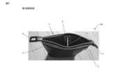
図6は、図5の状態におけるバッグ100の使用例を示す図である。ここで、本実施形態では、ヘッドフォン20を載置面10に載置した様子を示しているが、載置面10に載置するものはこれに限定されない。例えば、スマートフォン等の携帯情報端末、ペン、メガネ、ガム等の小物を載置面10に載置してもよい。
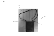
また、図1及び図2に示されるように、前面部1及び背面部2のフェルト9との境目付近には、紐部材取付リング8が設けられる。そして、必要に応じて、図7に示されるように、紐部材取付リング8を介して紐部材30の両端をバッグ100に取り付けてもよい。
以上説明したように、本実施形態によれば、バッグ100の上下を逆にした状態でテーブルにバッグ100を自立させ、変形誘発部7により形成された載置面10に物を載置することが可能となる。これにより、例えばカフェ等のように狭いテーブル上においても、ヘッドフォン20等の物の載置場所を確保することが可能となる。
本発明は、以下の形態でも実施可能である。
・上記実施形態では、連結部5,6の係合部51(T字部分)と開口61を互いに係合させたが、連結部5,6は、別の構成(例:ボタン、ハトメ、面ファスナー、紐)によって連結させてもよい。
・上記実施形態では、連結部5,6は、互いに係合させることによって連結させたが、連結部5,6は、磁力や粘着力によって互いに連結させてもよい。
・上記実施形態では、開口部3にファスナー4が設けられているが、ファスナー4は省略可能である。この場合、連結部5,6は、袋体の長手方向の両端に隣接した任意の位置に配置することができる。例えば、図9の領域Y及びZに配置することができる。この場合、例えば図8(a)に示されるように、例えば連結部5,6を袋体の内部に設けてもよい。そして、連結部5,6を互いに連結させることにより、図8(b)に示される状態となる。
・互いに対向する前面部及び背面部を有する袋体について説明したが、明確に前面部と背面部を区別できない形状のバッグについても適用可能である。かかる場合、袋体の一部を前面部とみなし、前面部と対向する箇所を背面部とみなす。
2.第2実施形態
次に、図9を用いて、本発明の第2実施形態について説明する。本実施形態は、第1実施形態に類似しており、形状維持部の構成の違いが主な相違点である。以下、相違点を中心に説明する。
次に、図9を用いて、本発明の第2実施形態について説明する。本実施形態は、第1実施形態に類似しており、形状維持部の構成の違いが主な相違点である。以下、相違点を中心に説明する。
本実施形態では、図9に示されるように、袋体内部に内部支持部材70が設けられており、内部支持部材70によって形状維持部が構成される。内部支持部材70によって前面部1及び背面部2が近接することが阻止されることによって、袋体が膨らんだ状態に維持される。かかる内部支持部材70は、バッグ100を変形させないときには、バッグ100の内部のポケット等に入れておいてもよい。また、その一部をバッグ100の内面(例えば領域Xで示される部分)に固定しておいてもよい。
内部支持部材70は、前面部1と背面部2の近接を阻止することができる任意の形状にすることができ、図9に示すような棒状であってよく、円形などの別の形状であってもよい。
3.第3実施形態
次に、本発明の第3実施形態について説明する。本実施形態は、第1実施形態に類似しており、形状維持部の構成の違いが主な相違点である。以下、相違点を中心に説明する。
次に、本発明の第3実施形態について説明する。本実施形態は、第1実施形態に類似しており、形状維持部の構成の違いが主な相違点である。以下、相違点を中心に説明する。
本実施形態では、袋体を構成する前面部1及び背面部2に、前面部1又は背面部2を変形させたときにその形状を維持する面形状維持部材が設けられており、面形状維持部材によって形状維持部が構成される。面形状維持部材は、例えば金属薄板のような容易に塑性変形させることができる部材で構成される。このような部材を前面部1及び背面部2に内蔵させるか又はその表面に貼り付けることによって、袋体が膨らんだ状態になるように前面部1及び背面部2を変形させると、面形状維持部材によって前面部1及び背面部2の形状が維持される。面形状維持部材は、前面部1及び背面部2の両方に設けることが好ましいが、一方のみに設けてもよい。
4.その他
上記実施形態では、バッグ100をヘッドフォンスタンドとして利用する例について説明したが、かかるバッグ100の使用方法はこれらに限定されない。例えば、バッグ100の前面部1又は背面部2若しくはその他の場所にスピーカー等の電子機器を組み込むことにより、電子機器として利用することができる。さらに、バッグ100を変形させた状態(つまり、通常と上下が逆になった状態)において模様やイラストを付し、オブジェとして利用することができる。
上記実施形態では、バッグ100をヘッドフォンスタンドとして利用する例について説明したが、かかるバッグ100の使用方法はこれらに限定されない。例えば、バッグ100の前面部1又は背面部2若しくはその他の場所にスピーカー等の電子機器を組み込むことにより、電子機器として利用することができる。さらに、バッグ100を変形させた状態(つまり、通常と上下が逆になった状態)において模様やイラストを付し、オブジェとして利用することができる。
1:前面部、2:背面部、3:開口部、4:ファスナー、5,6:連結部、7:変形誘発部、8:紐部材取付リング、9:フェルト、10:載置面、20:ヘッドフォン、30:紐部材、70:内部支持部材、41:スライダー、43:テープ、43:エレメント、51:係合部、52:切欠部、61:開口、100:バッグ
Claims (9)
- 互いに対向する前面部と背面部を有する袋体と、
前記袋体の上辺に設けられた開口部と、
前記開口部の閉口を阻止し且つ前記袋体を膨らんだ状態に維持する形状維持部と、
を有するバッグ。 - 前記形状維持部は、前記袋体の両端に隣接して設けられ且つ互いに連結可能な一対の連結部を備える、請求項1に記載のバッグ。
- 前記一対の連結部は、互いに係合可能な一対の係合部である、請求項2に記載のバッグ。
- 前記開口部にはファスナーが設けられ、
前記一対の連結部は、前記ファスナーの両端に設けられる、請求項2又は請求項3に記載のバッグ。 - 前記形状維持部は、前記袋体内部に設けられ且つ前記前面部と前記背面部が近接することを阻止する内部支持部材を備える、請求項1~請求項4の何れか1つに記載のバッグ。
- 前記形状維持部は、前記前面部及び前記背面部の少なくとも一方に設けられた面形状維持部材を備え、前記面形状維持部材は、前記面形状維持部材が設けられた面が変形されたときにその形状を維持するように構成される、請求項1~請求項5の何れか1つに記載のバッグ。
- 前記袋体の下辺側に、前記袋体の側面から前記袋体の中央側に向かって凸となる変形誘発部が設けられ、
前記変形誘発部により前記袋体の変形が誘発され、前記変形誘発部周辺に載置面が形成されるように構成される、
請求項1~請求項6の何れか1つに記載のバッグ。 - 袋体と、
前記袋体の上辺に設けられた開口部を備え、
前記袋体の下辺側に、前記袋体の側面から前記袋体の中央側に向かって凸となる変形誘発部が設けられ、
前記変形誘発部により前記袋体の変形が誘発され、前記変形誘発部周辺に載置面が形成されるように構成される、バッグ。 - 互いに連結可能な連結部を両端に有するファスナー。
Priority Applications (4)
| Application Number | Priority Date | Filing Date | Title |
|---|---|---|---|
| JP2018516924A JP7299599B2 (ja) | 2016-05-09 | 2017-04-21 | バッグ及びファスナー |
| CN201780016508.2A CN108778038A (zh) | 2016-05-09 | 2017-04-21 | 包以及拉链 |
| US16/091,603 US11089853B2 (en) | 2016-05-09 | 2017-04-21 | Bag and fastener |
| JP2023007136A JP2023052542A (ja) | 2016-05-09 | 2023-01-20 | バッグ及びファスナー |
Applications Claiming Priority (2)
| Application Number | Priority Date | Filing Date | Title |
|---|---|---|---|
| JP2016093597 | 2016-05-09 | ||
| JP2016-093597 | 2016-05-09 |
Publications (1)
| Publication Number | Publication Date |
|---|---|
| WO2017195571A1 true WO2017195571A1 (ja) | 2017-11-16 |
Family
ID=60266965
Family Applications (1)
| Application Number | Title | Priority Date | Filing Date |
|---|---|---|---|
| PCT/JP2017/016011 Ceased WO2017195571A1 (ja) | 2016-05-09 | 2017-04-21 | バッグ及びファスナー |
Country Status (4)
| Country | Link |
|---|---|
| US (1) | US11089853B2 (ja) |
| JP (2) | JP7299599B2 (ja) |
| CN (1) | CN108778038A (ja) |
| WO (1) | WO2017195571A1 (ja) |
Citations (2)
| Publication number | Priority date | Publication date | Assignee | Title |
|---|---|---|---|---|
| JPS5882114U (ja) * | 1981-11-30 | 1983-06-03 | 株式会社ヤマト屋 | 袋物 |
| WO2015128621A1 (en) * | 2014-02-27 | 2015-09-03 | Working Class Heroes Ltd | Headphone case |
Family Cites Families (15)
| Publication number | Priority date | Publication date | Assignee | Title |
|---|---|---|---|---|
| US4577376A (en) * | 1982-01-01 | 1986-03-25 | Clendinen Charles D | Snap fastener |
| JPH01297001A (ja) | 1988-02-23 | 1989-11-30 | Asics Corp | 靴用締付け装置 |
| JPH064732Y2 (ja) * | 1990-09-17 | 1994-02-09 | 純一 堀口 | 背負い式バツグ |
| US6006915A (en) * | 1998-11-09 | 1999-12-28 | The Mead Corporation | Case for audio device and headphone set |
| JP3124346U (ja) * | 2006-04-03 | 2006-08-17 | 株式会社ティーピーパック | 表示ラベル |
| JP3136723U (ja) * | 2007-05-31 | 2007-11-08 | 株式会社ヤマト屋 | バッグ |
| CN201182283Y (zh) * | 2008-03-06 | 2009-01-21 | 上海昆鸟工贸有限公司 | 可折叠收合的环保型超市购物袋 |
| CN201303668Y (zh) * | 2008-08-27 | 2009-09-09 | 刘丽香 | 车筐用多功能环保购物袋 |
| JP3149672U (ja) * | 2009-01-09 | 2009-04-09 | 株式会社ナカネ | ループ状に取り付ける反射具 |
| CN201591208U (zh) * | 2009-10-30 | 2010-09-29 | 马彩燕 | 一种后背式手提方包 |
| CN202407529U (zh) * | 2012-01-21 | 2012-09-05 | 尹丽平 | 一种一体式隐形眼镜盒 |
| US8850675B2 (en) | 2012-02-06 | 2014-10-07 | Hickies, Inc. | Fastening devices and systems and methods thereof |
| JP2014161559A (ja) * | 2013-02-26 | 2014-09-08 | Goldwin Inc | トートバッグ |
| JP2015029859A (ja) * | 2013-08-06 | 2015-02-16 | 岩井 一夫 | 肩掛けベルトのずり落ち防止具、及びそれを用いたショルダーバッグ |
| CN205053046U (zh) * | 2015-10-14 | 2016-03-02 | 杭州奥达化纤有限公司 | 一种粘扣结合带 |
-
2017
- 2017-04-21 WO PCT/JP2017/016011 patent/WO2017195571A1/ja not_active Ceased
- 2017-04-21 US US16/091,603 patent/US11089853B2/en active Active
- 2017-04-21 JP JP2018516924A patent/JP7299599B2/ja active Active
- 2017-04-21 CN CN201780016508.2A patent/CN108778038A/zh active Pending
-
2023
- 2023-01-20 JP JP2023007136A patent/JP2023052542A/ja active Pending
Patent Citations (2)
| Publication number | Priority date | Publication date | Assignee | Title |
|---|---|---|---|---|
| JPS5882114U (ja) * | 1981-11-30 | 1983-06-03 | 株式会社ヤマト屋 | 袋物 |
| WO2015128621A1 (en) * | 2014-02-27 | 2015-09-03 | Working Class Heroes Ltd | Headphone case |
Also Published As
| Publication number | Publication date |
|---|---|
| JP7299599B2 (ja) | 2023-06-28 |
| US11089853B2 (en) | 2021-08-17 |
| CN108778038A (zh) | 2018-11-09 |
| JPWO2017195571A1 (ja) | 2019-03-07 |
| US20190125047A1 (en) | 2019-05-02 |
| JP2023052542A (ja) | 2023-04-11 |
Similar Documents
| Publication | Publication Date | Title |
|---|---|---|
| US8950024B1 (en) | Covering | |
| USD969098S1 (en) | Mobile phone | |
| US10772411B2 (en) | Hands-free item carrying device | |
| JP2013501165A (ja) | アパレル及びアクセサリのための構造体及び方法 | |
| WO2017195571A1 (ja) | バッグ及びファスナー | |
| US10039360B2 (en) | Belongings pocket | |
| US10448677B2 (en) | Retractable pocket square and holder apparatus and method of use | |
| JP3206124U (ja) | 指輪ケース | |
| JP2006095261A (ja) | クリップ及びクリップケース | |
| USD976581S1 (en) | Wallet | |
| JP3136822U (ja) | ランドセルカバーのセット | |
| JP3235687U (ja) | マスク用クリップ | |
| JP5173448B2 (ja) | クリップ付きストラップ | |
| JP2018135151A (ja) | 台襟付きシャツの襟の形状保持具 | |
| JP2006295859A (ja) | 接着式アクセサリー | |
| JP3115329U (ja) | 冊子カバー | |
| CN220693298U (zh) | 一种带支架的音箱 | |
| JP3167843U (ja) | 鏡付きストラップ | |
| CN205410059U (zh) | 随身包 | |
| JP4353909B2 (ja) | リモコン装置 | |
| CN208539967U (zh) | 复合功能手机架结构 | |
| JP3167197U (ja) | 収納袋 | |
| TWM296797U (en) | Structure of simple support for decoration | |
| JP3189598U (ja) | 小物入れ | |
| JP3118621U (ja) | 物入れ付き座席 |
Legal Events
| Date | Code | Title | Description |
|---|---|---|---|
| ENP | Entry into the national phase |
Ref document number: 2018516924 Country of ref document: JP Kind code of ref document: A |
|
| NENP | Non-entry into the national phase |
Ref country code: DE |
|
| 121 | Ep: the epo has been informed by wipo that ep was designated in this application |
Ref document number: 17795932 Country of ref document: EP Kind code of ref document: A1 |
|
| 122 | Ep: pct application non-entry in european phase |
Ref document number: 17795932 Country of ref document: EP Kind code of ref document: A1 |