WO2017195596A1 - Structure de montage de capteur - Google Patents
Structure de montage de capteur Download PDFInfo
- Publication number
- WO2017195596A1 WO2017195596A1 PCT/JP2017/016480 JP2017016480W WO2017195596A1 WO 2017195596 A1 WO2017195596 A1 WO 2017195596A1 JP 2017016480 W JP2017016480 W JP 2017016480W WO 2017195596 A1 WO2017195596 A1 WO 2017195596A1
- Authority
- WO
- WIPO (PCT)
- Prior art keywords
- temperature detection
- electrode arrangement
- pair
- engagement
- temperature
- Prior art date
- Legal status (The legal status is an assumption and is not a legal conclusion. Google has not performed a legal analysis and makes no representation as to the accuracy of the status listed.)
- Ceased
Links
Images








Classifications
-
- G—PHYSICS
- G01—MEASURING; TESTING
- G01K—MEASURING TEMPERATURE; MEASURING QUANTITY OF HEAT; THERMALLY-SENSITIVE ELEMENTS NOT OTHERWISE PROVIDED FOR
- G01K1/00—Details of thermometers not specially adapted for particular types of thermometer
- G01K1/14—Supports; Fastening devices; Arrangements for mounting thermometers in particular locations
-
- G—PHYSICS
- G01—MEASURING; TESTING
- G01K—MEASURING TEMPERATURE; MEASURING QUANTITY OF HEAT; THERMALLY-SENSITIVE ELEMENTS NOT OTHERWISE PROVIDED FOR
- G01K7/00—Measuring temperature based on the use of electric or magnetic elements directly sensitive to heat ; Power supply therefor, e.g. using thermoelectric elements
- G01K7/16—Measuring temperature based on the use of electric or magnetic elements directly sensitive to heat ; Power supply therefor, e.g. using thermoelectric elements using resistive elements
- G01K7/22—Measuring temperature based on the use of electric or magnetic elements directly sensitive to heat ; Power supply therefor, e.g. using thermoelectric elements using resistive elements the element being a non-linear resistance, e.g. thermistor
-
- H—ELECTRICITY
- H01—ELECTRIC ELEMENTS
- H01M—PROCESSES OR MEANS, e.g. BATTERIES, FOR THE DIRECT CONVERSION OF CHEMICAL ENERGY INTO ELECTRICAL ENERGY
- H01M10/00—Secondary cells; Manufacture thereof
- H01M10/42—Methods or arrangements for servicing or maintenance of secondary cells or secondary half-cells
- H01M10/48—Accumulators combined with arrangements for measuring, testing or indicating the condition of cells, e.g. the level or density of the electrolyte
- H01M10/486—Accumulators combined with arrangements for measuring, testing or indicating the condition of cells, e.g. the level or density of the electrolyte for measuring temperature
-
- H—ELECTRICITY
- H01—ELECTRIC ELEMENTS
- H01M—PROCESSES OR MEANS, e.g. BATTERIES, FOR THE DIRECT CONVERSION OF CHEMICAL ENERGY INTO ELECTRICAL ENERGY
- H01M50/00—Constructional details or processes of manufacture of the non-active parts of electrochemical cells other than fuel cells, e.g. hybrid cells
- H01M50/50—Current conducting connections for cells or batteries
- H01M50/543—Terminals
- H01M50/547—Terminals characterised by the disposition of the terminals on the cells
- H01M50/55—Terminals characterised by the disposition of the terminals on the cells on the same side of the cell
-
- H—ELECTRICITY
- H01—ELECTRIC ELEMENTS
- H01M—PROCESSES OR MEANS, e.g. BATTERIES, FOR THE DIRECT CONVERSION OF CHEMICAL ENERGY INTO ELECTRICAL ENERGY
- H01M50/00—Constructional details or processes of manufacture of the non-active parts of electrochemical cells other than fuel cells, e.g. hybrid cells
- H01M50/50—Current conducting connections for cells or batteries
- H01M50/543—Terminals
- H01M50/552—Terminals characterised by their shape
- H01M50/553—Terminals adapted for prismatic, pouch or rectangular cells
-
- Y—GENERAL TAGGING OF NEW TECHNOLOGICAL DEVELOPMENTS; GENERAL TAGGING OF CROSS-SECTIONAL TECHNOLOGIES SPANNING OVER SEVERAL SECTIONS OF THE IPC; TECHNICAL SUBJECTS COVERED BY FORMER USPC CROSS-REFERENCE ART COLLECTIONS [XRACs] AND DIGESTS
- Y02—TECHNOLOGIES OR APPLICATIONS FOR MITIGATION OR ADAPTATION AGAINST CLIMATE CHANGE
- Y02E—REDUCTION OF GREENHOUSE GAS [GHG] EMISSIONS, RELATED TO ENERGY GENERATION, TRANSMISSION OR DISTRIBUTION
- Y02E60/00—Enabling technologies; Technologies with a potential or indirect contribution to GHG emissions mitigation
- Y02E60/10—Energy storage using batteries
Definitions
- the technology disclosed in this specification relates to a sensor mounting structure.
- a battery module in which a plurality of single cells are connected side by side is used as a power supply device for an electric vehicle or a hybrid vehicle.
- a battery module since the life and the like are adversely affected when the unit cell is overheated, means for monitoring the temperature of the unit cell is taken.
- the thermistor In order to monitor the temperature of the unit cell, the thermistor is covered with an insulating resin surrounding part, lock parts are provided on both the left and right sides of the surrounding part through flexible parts, and a locking part is provided on the base plate (resin component) on the battery side.
- the structure which attaches a thermistor to a battery case by engaging is devised (refer patent document 1). When attached to the battery case, the thermistor is urged by the flexible portion and is in close contact with the upper surface of the battery case.
- the entire structure for attaching the sensor is complicated by the amount through the base plate. Further, since the battery and the base plate have mutually independent dimensional tolerances, there may be a relative displacement between the battery and the thermistor. When such a position shift occurs, the thermistor may float or tilt with respect to the battery case, and the temperature measurement accuracy may be reduced. In order to prevent the temperature measurement accuracy from being lowered, it is necessary to increase the spring stroke of the flexible portion, which complicates the mounting structure.
- the sensor mounting structure disclosed in this specification is a sensor mounting structure for mounting a temperature sensor to a power storage element
- the power storage element includes an electrode terminal and a case wall, and the outer surface of the case wall.
- an insulating member that holds the electrode terminal while being insulated from the case wall by being assembled to the case wall, and the temperature measuring sensor holds the temperature detecting element,
- a temperature detection unit having a temperature detection surface in contact with the electrode arrangement surface; an engagement unit engaged with the insulating member; and a spring unit that closely contacts the temperature detection unit with the electrode arrangement surface.
- the thermistor is attached to the battery via the conventional base plate.
- the entire structure of sensor mounting can be simplified by the amount not via the base plate.
- the influence of the dimensional tolerance can be reduced by the amount not via the base plate, the spring structure for bringing the temperature detection element into close contact with the electrode arrangement surface can be simplified. As described above, it is possible to ensure the accuracy of temperature measurement while simplifying the configuration for mounting the sensor.
- the spring portion includes a first displacement portion that continues from the temperature detection portion, and an adjustment portion that has a second displacement portion that is displaced toward and away from the first displacement portion; and A pressing portion that is connected to the second displacement portion and is inclined toward the electrode arrangement surface as the distance from the temperature detection portion increases, and the insulating member presses the inclination portion toward the electrode arrangement surface.
- the temperature measuring sensor when the pressing portion presses the inclined portion toward the electrode arrangement surface, the temperature measuring sensor is deformed so that the inclination of the inclined portion becomes loose and the pair of displacement portions are separated from each other, The temperature detection surface is pressed toward the electrode arrangement surface.
- the temperature detection surface can be brought into close contact with the electrode arrangement surface, and the accuracy of temperature measurement can be ensured.
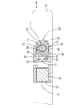
- Embodiment 1 the perspective view of the cell to which the temperature sensor was attached In Embodiment 1, the partial enlarged plan view of the cell to which the temperature sensor is attached In embodiment 1, the partial expanded side view of the cell with which the temperature sensor was attached AA line sectional view of FIG. Enlarged view inside circle R1 in FIG.
- the partial expanded side view of the cell of Embodiment 1 BB sectional view of FIG.
- Side view of temperature sensor of embodiment 1 CC sectional view of FIG.
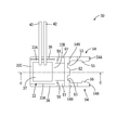
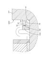
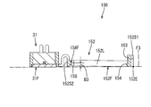
- Embodiment 2 the perspective view of the cell to which the temperature sensor was attached In Embodiment 2, the partial expanded plan view of the cell with which the temperature sensor was attached In embodiment 2, the partial expanded side view of the cell with which the temperature sensor was attached DD sectional view of FIG. Enlarged view inside circle R2 in FIG. Enlarged view inside circle R3 in FIG. Enlarged view inside circle R4 in FIG.
- the partial expanded side view of the cell of Embodiment 2. EE sectional view of FIG.
- Plan view of temperature sensor of embodiment 2 FF sectional view of FIG.
- the sensor mounting structure of the first embodiment is a configuration for mounting the temperature sensor 30 to the battery case 11 (corresponding to the case) of the unit cell 10 (corresponding to the storage element).
- the unit cell 10 includes a battery case 11 that houses a power generation element (not shown), a pair of positive and negative electrode terminals 14P and 14N, and a pair of insulators 21P and 21N.
- the battery case 11 is made of metal, and includes a case main body 12 that is a rectangular container having an opening on one side, and a cover plate 13 (corresponding to a case wall) that is disposed so as to close the opening of the case main body 12. I have.
- the cover plate 13 is an elongated rectangular plate-like member, and the outer side surface (the upper surface in FIG. 3) is an electrode arrangement surface 13F.
- a pair of positive and negative electrode terminals 14P, 14N protrudes from the electrode arrangement surface 13F.
- the electrode terminals 14P and 14N have a cylindrical shape and are erected vertically to the electrode arrangement surface 13F.
- Each of the pair of insulators 21P and 21N is a member that is assembled to the cover plate 13 and holds each of the pair of electrode terminals 14P and 14N while being insulated from the battery case 11.
- One insulator 21P (corresponding to an insulating member) of the pair of insulators 21P and 21N has a configuration for attaching the temperature sensor 30.
- the insulator 21 ⁇ / b> P includes a main body portion 22, a pair of positioning ribs 26 and 26, and a pressing wall 27 (corresponding to a pressing portion).
- the main body 22 is a cylindrical portion that is arranged to protrude outward from the electrode arrangement surface 13 ⁇ / b> F, and has a hole 22 ⁇ / b> H at the center. Electrode terminal 14P is inserted.
- the main body 22 has a pair of engaging recesses 23 and 23 for holding the temperature measuring sensor 30. Since the pair of engaging recesses 23 and 23 have the same configuration, one engaging recess 23 will be described in detail below, and the other engaging recess 23 will be described as one engaging recess 23. The same components as those in FIG.
- the engaging recess 23 is recessed with the outer peripheral surface 22F of the main body 22 as a reference, and is arranged with a gap in parallel with the electrode arrangement surface 13F and the electrode arrangement surface 13F.
- the recessed portion is defined by a ceiling surface 24 to be formed and a back wall surface 25 that is retracted and positioned with respect to the outer peripheral surface 22F of the main body portion 22 and connects the electrode arrangement surface 13F and the ceiling surface 24.
- the rear wall surface 25 extends from the outer peripheral surface 22 ⁇ / b> F of the main body 22 to the riding surface 25 ⁇ / b> A extending in parallel to the long side of the cover plate 13, and the riding surface 25 ⁇ / b> A.
- an engagement receiving surface 25B extending vertically (parallel to the short side of the cover plate 13) and an inclined surface 25C extending obliquely from the engagement receiving surface 25B and continuing to the outer peripheral surface 22F of the main body portion 22. is doing.
- Each of the pair of positioning ribs 26, 26 is a streak-like wall portion extending in parallel with the long side of the cover plate 13 from the outer peripheral surface 22F of the main body portion 22, as shown in FIGS. They are arranged in parallel.
- the pressing wall 27 is a plate-like portion extending from the outer peripheral surface 22F of the main body 22 in the same direction as the pair of positioning ribs 26, 26, and is spaced from the electrode arrangement surface 13F.
- a pair of positioning ribs 26, 26 are arranged between the electrode arrangement surfaces 13F.
- one surface of the pressing wall 27 (a surface facing the electrode arrangement surface 13 ⁇ / b> F) is flush with the ceiling surface 24.
- the temperature measuring sensor 30 includes a temperature detecting unit 31 and an assembling unit 51 connected to the temperature detecting unit 31.
- the temperature detection unit 31 is connected to the rectangular container-shaped element housing part 32, the temperature detection element 41 connected to the electric wire 42 and disposed inside the element storage part 32, and a resin seal that seals the temperature detection element 41.
- a portion 37 and a pair of leg portions 36 and 36 extending from the element housing portion 32 are provided.
- the element accommodating part 32 is comprised by the frame part 33 and the heat exchanger plate 35, as shown in FIG.
- the frame portion 33 is a rectangular tube-shaped portion having openings 34A and 34B at both ends, and as shown in FIG. 10, a pair of first portions arranged in parallel to each other.
- Side walls 33A, 33A, and a pair of first side walls 33A, 33A are provided with a second side wall 33B and a third side wall 33C.
- the heat transfer plate 35 is a metal rectangular plate disposed so as to close one opening 34 ⁇ / b> A of the frame portion 33.
- the surface on which the heat transfer plate 35 is disposed is a temperature detection that abuts on the electrode placement surface 13 ⁇ / b> F in a state where the temperature sensor 30 is attached to the unit cell 10 as shown in FIGS. 3 and 12. It is a surface 31F.
- Each of the pair of leg portions 36, 36 is a plate-like portion extending from each of the two first side walls 33A, as shown in FIGS. Each leg portion 36 extends along the edge on the temperature detection surface 31F side in each first side wall 33A.
- a temperature detection element 41 is disposed in contact with the heat transfer plate 35 inside the frame portion 33, and electric wires 42 and 42 connected to the temperature detection element 41 are connected to the frame 33. It is led out from the other opening 34 ⁇ / b> B of the portion 33.
- a resin sealing portion 37 is formed by filling a sealing resin inside the frame portion 33, and a temperature detection element 41 is embedded in the resin sealing portion 37.
- the assembly portion 51 (corresponding to the spring portion) includes a pair of extending portions 56 and 56 that are continuous from the temperature detecting portion 31 and a pair of adjusting portions 61 that are continuous from the pair of extending portions 56 and 56. , 61, and a pair of engaging arms 54, 54 (corresponding to an engaging portion and an inclined portion) connected from the pair of adjusting portions 61, 61 via the positioning receiving portion 52.
- each of the pair of extending portions 56, 56 is a second portion from each of the two corner portions formed by the first side wall 33 ⁇ / b> A and the second side wall 33 ⁇ / b> B in the frame portion 33. This is a plate-like portion extending perpendicular to the side wall 33B. Each extending portion 56 extends along the edge on the temperature detection surface 31F side in each second side wall 33B.
- each of the pair of adjusting portions 61, 61 has a U-shape that protrudes toward the side opposite to the electrode arrangement surface 13 ⁇ / b> F when the temperature sensor 30 is attached to the unit cell 10. It is a curved, leaf-like part.
- a pair of U-shaped vertical bar portions are a pair of displacement parts (a first displacement part 62 and a second displacement part 63) that are displaced toward and away from each other.
- one end of the first displacement portion 62 and one end of the second displacement portion 63 are connected by an arch-shaped connection portion 64.
- Each adjusting portion 61 has one end (an edge opposite to the connecting portion 64 in the first displacement portion 62) connected to each extending portion 56, and the other end (the connecting portion 64 in the second displacement portion 63). The edge on the opposite side to the terminal is connected to the positioning receiving portion 52.
- the positioning receiving portion 52 is an elongated plate-like portion extending in a direction parallel to the second side wall 33 ⁇ / b> B, and has two positioning recesses 53.
- Each positioning recess 53 is a recess that is recessed in the positioning receiving portion 52 with reference to the side edge opposite to the temperature detecting portion 31, and can receive the respective leading end portions of the pair of positioning ribs 26, 26 therein. It has become.
- each of the pair of engagement arms 54 and 54 is a generally elongated plate-like portion that extends in the opposite direction from the temperature detection unit 31 from both ends of the positioning receiving unit 52.
- the pair of engagement arms 54, 54 are arranged in parallel to each other.
- one plate surface of the front and back surfaces of each engagement arm 54 is a battery facing surface 54 ⁇ / b> F that faces the electrode placement surface 13 ⁇ / b> F with the temperature sensor 30 attached to the unit cell 10. .
- each engagement arm 54 has one end connected to the positioning receiving portion 52 as a fixed end 54B and the other side as a free end 54A. On the other hand, it can bend in the direction of approaching or separating.
- Each engagement arm 54 includes an engagement protrusion 55 that is engaged with the engagement receiving surface 25B of the insulator 21P. As shown in FIG. 10, the engagement protrusion 55 is a plate-like portion protruding inward (in a direction approaching the mating engagement arm 54) from the free end 54 ⁇ / b> A of the engagement arm 54.
- each engagement arm 54 in the state where the temperature sensor 30 is attached to the unit cell 10, the temperature detection unit 31 is arranged with the entire temperature detection surface 31 ⁇ / b> F being in close contact with the electrode arrangement surface 13 ⁇ / b> F.
- the positioning receiving portion 52 and the fixed end 54B of each engagement arm 54 are arranged with a clearance C1 with respect to the electrode arrangement surface 13F.
- each engagement arm 54 inclines so that it may approach the electrode arrangement
- Each engagement arm 54 is in a state where the temperature measuring sensor 30 is not assembled to the unit cell 10 (the state shown in FIG. 11), and the state where the temperature measuring sensor 30 is assembled to the unit cell 10 (the state shown in FIG. 3). ) With respect to the temperature detection surface 31F.
- the temperature sensor 30 In the state where the temperature sensor 30 is not assembled to the unit cell 10, it includes the edge portions 54 BE and 54 BE opposite to the cell facing surface 54 F at the fixed ends 54 B and 54 B of the two engagement arms, and temperature detection
- the surface parallel to the surface 31F is defined as a first virtual surface F1
- the free ends 54A of the two engagement arms 54 include the edge portions 54AE and 54AE on the battery facing surface 54F side
- the surface parallel to the temperature detection surface 31F is defined as a second surface.
- the distance D1 between the electrode arrangement surface 13F and the pressing wall 27 is larger than the thickness (distance from the battery facing surface 54F to the opposite surface) T1 of the engagement arms 54, 54, It is smaller than the distance D2 between the first virtual surface F1 and the second virtual surface F2 (see FIGS. 5 and 11).
- the temperature sensor 30 When attaching the temperature sensor 30 to the unit cell 10, first, the temperature sensor 30 is placed on the electrode arrangement surface 13F, the temperature detection surface 31F faces the electrode arrangement surface 13F, and the engagement arms 54 and 54 are the insulator 21P. Position it so that it faces. In this state, the temperature measuring sensor 30 is pressed toward the insulator 21 ⁇ / b> P, and each engagement arm 54 is caused to enter each engagement recess 23. Each engagement arm 54 bends outward (in a direction away from the mating engagement arm 54), and the engagement protrusion 55 rides on the ride surface 25A.
- the engagement arms 54 and 54 enter the gap between the pressing wall 27 and the electrode arrangement surface 13 ⁇ / b> F.
- each engagement arm 54 is provided.
- the pressing wall 27 presses the fixed ends 54B and 54B of the engagement arms 54 and 54 toward the electrode arrangement surface 13F.
- the inclination of the engagement arms 54, 54 becomes gentler than that of a single unit that is not assembled to the unit cell 10, and the pair of adjustment units 61, 61 expand.
- the first displacement part 62 and the second displacement part 63 are deformed). With this deformation, the temperature detection surface 31F is pressed toward the electrode arrangement surface 13F. In this way, the temperature detection surface 31F can be brought into close contact with the electrode arrangement surface 13F, and the accuracy of temperature measurement can be ensured. Further, the dimensional tolerance of the unit cell 10 can be absorbed by the engagement arms 54, 54 and the pair of adjusting portions 61, 61 being deformed by a deformation amount corresponding to the dimensional tolerance of the unit cell 10.
- the sensor mounting structure of the present embodiment is a structure for mounting the temperature sensor 30 to the unit cell 10.
- the unit cell 10 includes an electrode terminal 14P, a battery case 11, and an insulator 21P.
- the battery case 11 includes a lid plate 13, and the outer surface of the lid plate 13 is an electrode arrangement surface 13F.
- the insulator 21 ⁇ / b> P is a member that is assembled to the lid plate 13 and holds the electrode terminal 14 ⁇ / b> P while being insulated from the lid plate 13.
- the temperature sensor 30 holds the temperature detection element 41 and has a temperature detection part 31 having a temperature detection surface 31F that contacts the electrode arrangement surface 13F, and a pair of engagement arms 54 and 54 that engage with the insulator 21P. And an assembling portion 51 for bringing the temperature detecting element 41 into close contact with the electrode arrangement surface 13F.
- a thermistor can be connected via the conventional base plate.
- the entire structure of sensor attachment can be simplified by the amount not via the base plate.
- the influence of the dimensional tolerance can be reduced by the amount not via the base plate, the spring structure for bringing the temperature detecting element 41 into close contact with the electrode arrangement surface 13F can be simplified. From the above, it is possible to secure the accuracy of temperature measurement while simplifying the configuration for mounting the temperature sensor 30.
- each of the pair of adjusting units 61 and 61 is connected to the first displacement unit 62 that is continuous from the temperature detection unit 31 and the pair of engagement arms 54 and 54, and is in the direction of approaching and separating from the first displacement unit 62.
- the pair of engagement arms 54, 54 are inclined so as to approach the electrode arrangement surface 13F as they are separated from the temperature detection unit 31, and the insulator 21P is engaged with the engagement arm 45. , 45 is pressed against the electrode arrangement surface 13F.
- the temperature measuring sensor 30 when the pressing wall 27 presses the engagement arms 54 and 54 toward the electrode arrangement surface 13F, the temperature measuring sensor 30 has the inclination of the engagement arms 54 and 54 loosened, and a pair of The adjustment portions 61 and 61 are deformed so as to expand, and the temperature detection surface 31F is pressed toward the electrode arrangement surface 13F.
- the temperature detection surface 31F can be brought into close contact with the electrode arrangement surface 13F to ensure the accuracy of temperature measurement.
- FIG. 1 The sensor mounting structure of the present embodiment is a configuration for mounting the temperature sensor 130 to the battery case 11 (corresponding to the case) of the unit cell 110 (corresponding to the storage element) as in the first embodiment (see FIG. 13). ).
- the present embodiment is different from the first embodiment in the configuration of an insulator 121P (corresponding to an insulating member) and an assembly part 151 (corresponding to a spring part).
- the same components as those in the first embodiment are denoted by the same reference numerals and description thereof is omitted.
- the insulator 121 ⁇ / b> P includes a main body 122 having an engagement recess 123, a pair of positioning ribs 126 and 126, and a pressing wall 127 (corresponding to a pressing portion).
- the main body 122 is a rectangular parallelepiped portion that protrudes outward from the electrode arrangement surface 13 ⁇ / b> F, and has a hole 122 ⁇ / b> H at the center. Electrode terminal 14P is inserted.
- the four side wall surfaces (surfaces perpendicular to the cover plate 13) of the main body 122 are formed on a pair of long walls 122 ⁇ / b> L and 122 ⁇ / b> L parallel to the long side of the cover plate 13 and the short side of the cover plate 13. It consists of a pair of parallel short walls 122S1, 122S2.
- the engagement recess 123 is recessed inward (in the direction toward the other short wall 122S2) with respect to one short wall 122S1 of the pair of short walls 122S1, 122S2,
- the electrode placement surface 13F, the engagement receiving surface 124 arranged in parallel with the electrode placement surface 13F with a gap between them, and the recess locating with respect to the short wall 122S1, are engaged with the electrode placement surface 13F. It is a recess defined by a back wall 125 connecting the surface 124.
- the engaging recess 123 is disposed at the center position between the pair of long sides.
- each of the pair of positioning ribs 126 and 126 is a streak-like wall portion extending perpendicularly from the other short wall 122 ⁇ / b> S ⁇ b> 2 of the main body portion 122, and is disposed in parallel to each other. .
- the holding wall 127 is a plate-like portion extending vertically from the other short wall 122S2 of the main body 122, and is spaced from the electrode arrangement surface 13F. They are arranged in parallel. As shown in FIG. 20, the holding wall 127 is disposed with a pair of positioning ribs 26, 26 sandwiched between the electrode placement surface 13 ⁇ / b> F, and a central portion sandwiched between the pair of positioning ribs 126, 126 is a positioning rib. It extends to the same position as 126, 126, and the part outside it is retracted from the central part. In addition, in FIG.16, FIG18 and FIG.19, the cross section of the cell 110 is shown typically.
- the assembly portion 151 (corresponding to the spring portion) includes a pair of extension portions 56 and 56 that are continuous from the temperature detection portion 31 and a pair of adjustment portions 161 that are continuous from the pair of extension portions 56 and 56. , 161 and an engagement frame 152 (corresponding to an engagement portion and an inclined portion) continuous from the pair of adjustment portions 161, 161.
- the engagement frame 152 is a rectangular frame-shaped portion, and is a pair arranged in parallel to the second side wall 33 ⁇ / b> B of the temperature detection unit 31 and spaced from each other.
- FIG. 23 the engagement frame 152 is a rectangular frame-shaped portion, and is a pair arranged in parallel to the second side wall 33 ⁇ / b> B of the temperature detection unit 31 and spaced from each other.
- the engagement frame 152 is disposed so as to surround the insulator 121P, each of the pair of long frame portions 152L and 152L is disposed along each of the pair of long walls 122L, and one short frame portion 152S1. Is disposed along one short wall 122S1, and the other short frame portion 152S2 is disposed along the other short wall 122S2.
- the end surface facing the electrode arrangement surface 13 ⁇ / b> F is a battery facing surface 152 ⁇ / b> F in a state where the temperature sensor 130 is assembled to the unit cell 110.
- one short frame portion 152S1 separated from the temperature detection unit 31 has a high-back portion 152H as shown in FIGS.
- the high-back portion 152H is a central portion between the pair of long frame portions 152L and 152L, and the height (the distance from the battery facing surface 152F to the opposite end surface) is the height of other portions in the assembly portion 151. It is a larger part.
- a part of the high-back portion 152H is a lock arm 153.
- the high-back portion 152H has a pair of slits S extending from the battery facing surface 152F and spaced apart from each other, and a portion sandwiched between the pair of slits S is a lock arm. 153.
- the lock arm 153 can be bent in the direction of approaching or separating from the counterpart short frame portion 152S2 with one end on the battery facing surface 152F side as a free end and the opposite side as a fixed end.
- a claw 154 is provided. As shown in FIG. 23, the locking claw 154 is a protrusion that protrudes from the free end of the lock arm 153 toward the counterpart short frame portion 152S2.
- the other short frame portion 152S2 close to the temperature detection unit 31 has a positioning recess 155 and is disposed inside the positioning recess 155, as shown in FIGS.
- the engagement protrusion 158 is provided.
- the positioning recess 155 is recessed with reference to the inner side surface of the short frame portion 152S2 (the surface facing the counterpart short frame portion 152S1), and a rear wall surface 156 parallel to the inner side surface of the short frame portion 152S2.
- the positioning recess 155 can receive the tip portions of the pair of positioning ribs 126 and 126.
- the engaging protrusion 158 is a protrusion that protrudes from the rear wall surface 156 toward the counterpart short frame portion 152 ⁇ / b> S ⁇ b> 1, extends perpendicularly to the rear wall surface 156, and holds the holding wall 127. And a contact surface 158F that contacts the surface.
- each of the pair of adjustment units 161 and 161 has a U-shape that protrudes toward the opposite side of the electrode arrangement surface 13 ⁇ / b> F with the temperature sensor 130 attached to the unit cell 110. It is a curved, leaf-like part.
- a pair of U-shaped vertical bar portions are, as shown in FIG. 17, a pair of displacement parts (a first displacement part 162 and a second displacement part 163) that are displaced in directions toward and away from each other.
- a pair of displacement parts a first displacement part 162 and a second displacement part 163 that are displaced in directions toward and away from each other.
- one end of the first displacement portion 162 and one end of the second displacement portion 163 are connected by an arch-shaped connection portion 164.
- Each adjusting portion 161 has one end (the end opposite to the connecting portion 164 in the first displacement portion 162) connected to each extending portion 56, and the other end (second displacement portion). 163 is connected to the end of the short frame portion 152S2 opposite to the battery facing surface 152F.
- the temperature detection unit 31 is arranged with the entire temperature detection surface 31 ⁇ / b> F being in close contact with the electrode arrangement surface 13 ⁇ / b> F.
- the short frame portion 152S2 is arranged with a clearance C2 with respect to the electrode arrangement surface 13F.
- the engagement frame 152 inclines so that it may approach the electrode arrangement
- the engagement frame 152 is a state in which the temperature sensor 30 is assembled to the unit cell 10 (the state in FIG. 15) when the temperature sensor 130 is not assembled to the unit cell 110 (the state in FIG. 25). Rather than the temperature detection surface 31F.
- the edge 152E on the battery facing surface 152F side of the short frame portion 152S1 is positioned within the surface of the extended surface F3 obtained by extending the temperature detection surface 31F. is doing. Further, the distance D3 between the extension surface F3 and the contact surface 158F is larger than the distance D4 between the pressing wall 127 and the electrode arrangement surface 13F (see FIGS. 18 and 25).
- the temperature sensor 130 When attaching the temperature sensor 130 to the single cell 110, first, the temperature sensor 130 is placed on the electrode arrangement surface 13F, the temperature detection surface 31F faces the electrode arrangement surface 13F, and the engagement frame 152 surrounds the insulator 121P. Arrange as follows. In this state, when the engagement frame 152 is pressed toward the electrode arrangement surface 13F, the locking claw 154 rides on the short wall 122S1 of the main body 122, and the lock arm 153 is bent outward.
- each of the tip portions of the two positioning ribs 126 and 126 enters each of the two positioning recesses 155, so that the temperature measuring sensor 130 has the outer peripheral surface 22 ⁇ / b> F of the main body portion 122. Is positioned so as not to rotate along.
- the pressing wall 127 is engaged with the engaging protrusion 158. Is pressed toward the electrode placement surface 13F. That is, the pressing wall 127 is in a state of pressing the short frame portion 152S2 toward the electrode arrangement surface 13F.
- the temperature measuring sensor 130 is configured such that the inclination of the engagement frame 152 becomes gentler than that of a single unit that is not assembled to the unit cell 110, and the pair of adjustment units 161 and 161 are expanded (first displacement).
- the portion 162 and the second displacement portion 163 are deformed so that they are separated from each other, and the temperature detection surface 31F is pressed toward the electrode placement surface 13F. In this way, the temperature detection surface 31F can be brought into close contact with the electrode arrangement surface 13F, and the accuracy of temperature measurement can be ensured.
- the dimensional tolerance of the unit cell 110 can be absorbed by the engagement frame 152 and the pair of adjusting units 161 and 161 being deformed by a deformation amount corresponding to the dimensional tolerance of the unit cell 110.
- the sensor mounting structure of the present embodiment is a structure for mounting the temperature sensor 130 to the unit cell 110, and the unit cell 110 includes the electrode terminal 14P, the battery case 111, and the insulator 121P.
- the battery case 111 includes a lid plate 13, and the outer surface of the lid plate 13 is an electrode arrangement surface 13F.
- the insulator 121 ⁇ / b> P is a member that is assembled to the lid plate 13 and holds the electrode terminal 14 ⁇ / b> P while being insulated from the lid plate 13.
- the temperature sensor 130 includes the temperature detection unit 31 that holds the temperature detection element 41 and has a temperature detection surface 31F that contacts the electrode arrangement surface 13F, and an engagement frame 152 that engages the insulator 121P. And an assembling portion 151 for bringing the detection element 41 into close contact with the electrode arrangement surface 13F.
- the insulator provided in the single battery 110 is used, and the engagement frame 152 of the temperature sensor 130 is engaged with the insulator 121P. Therefore, the thermistor is attached to the battery via the conventional base plate.
- the entire structure of sensor mounting can be simplified by the amount not via the base plate.
- the spring structure for bringing the temperature detection surface 31F into close contact with the electrode arrangement surface 13F can be simplified. As described above, it is possible to ensure the accuracy of temperature measurement while simplifying the configuration for attaching the temperature sensor 130.
- each of the pair of adjustment units 161 and 161 is connected to the first displacement unit 162 connected to the temperature detection unit 31 and the engagement frame 152, and is displaced in a direction approaching and separating from the first displacement unit 162.
- 2 displacement portion 63, and the engagement frame 152 is inclined so as to be closer to the electrode placement surface 13F as it is farther from the temperature detection portion 31, and the insulator 121P moves the engagement frame 152 toward the electrode placement surface 13F.
- a pressing wall 127 for pressing is provided.
- the temperature measuring sensor 130 has a gentle inclination of the engagement frame 152 when the pressing wall 127 presses the engagement frame 152 toward the electrode arrangement surface 13F, and the pair of adjustment portions 161, 161 is deformed so as to expand, and the temperature detection surface 31F is pressed toward the electrode arrangement surface 13F.
- the temperature detection surface 31F can be brought into close contact with the electrode arrangement surface 13F to ensure the accuracy of temperature measurement.
- the temperature detection element 41 is a thermistor.
- the temperature detection element is not limited to the thermistor, and any element capable of detecting the temperature can be appropriately selected.
- the adjustment portions 61 and 161 are U-shaped, but the shape of the adjustment portion is not limited to that in the above embodiment.
- the first displacement portion and the second displacement portion are connected portions. It may be V-shaped connected without being interposed.
- the engaging arm 54 and the engaging frame 152 are inclined portions, but the inclined portion may be provided separately from the engaging portion.
Landscapes
- Chemical & Material Sciences (AREA)
- Chemical Kinetics & Catalysis (AREA)
- Electrochemistry (AREA)
- General Chemical & Material Sciences (AREA)
- Physics & Mathematics (AREA)
- General Physics & Mathematics (AREA)
- Engineering & Computer Science (AREA)
- Manufacturing & Machinery (AREA)
- Nonlinear Science (AREA)
- Secondary Cells (AREA)
- Measuring Temperature Or Quantity Of Heat (AREA)
- Battery Mounting, Suspending (AREA)
Abstract
L'invention concerne une structure de montage de capteur pour monter un capteur de mesure de température 30 sur une batterie unitaire 10, la batterie unitaire 10 comprenant une borne d'électrode 14P, un boîtier de batterie 11 et un isolant 21P. Le boîtier de batterie 11 comprend une plaque de couvercle 13, et une surface externe de la plaque de couvercle 13 sert de surface de disposition d'électrode 13F. L'isolateur 21P est un élément qui est assemblé sur la plaque de couvercle 13 et qui porte la borne d'électrode 14P tout en isolant la borne d'électrode 14P de la plaque de couvercle 13. En outre, le capteur de mesure de température 30 comprend une section de détection de température 31 qui porte l'élément de détection de température 41 et qui a une surface de détection de température 31F qui est en contact avec la surface de disposition d'électrode 13F, et une section d'assemblage 51 qui comprend une paire de bras de mise en prise 54, 54 qui viennent en prise avec l'isolateur 21P et qui amènent l'élément de détection de température 41 en contact étroit avec la surface de disposition d'électrode 13F.
Priority Applications (2)
| Application Number | Priority Date | Filing Date | Title |
|---|---|---|---|
| CN201780026157.3A CN109073475B (zh) | 2016-05-12 | 2017-04-26 | 传感器的安装结构 |
| US16/099,866 US11340120B2 (en) | 2016-05-12 | 2017-04-26 | Sensor mounting structure |
Applications Claiming Priority (2)
| Application Number | Priority Date | Filing Date | Title |
|---|---|---|---|
| JP2016-095950 | 2016-05-12 | ||
| JP2016095950A JP6279651B2 (ja) | 2016-05-12 | 2016-05-12 | センサの取付構造 |
Publications (1)
| Publication Number | Publication Date |
|---|---|
| WO2017195596A1 true WO2017195596A1 (fr) | 2017-11-16 |
Family
ID=60267564
Family Applications (1)
| Application Number | Title | Priority Date | Filing Date |
|---|---|---|---|
| PCT/JP2017/016480 Ceased WO2017195596A1 (fr) | 2016-05-12 | 2017-04-26 | Structure de montage de capteur |
Country Status (4)
| Country | Link |
|---|---|
| US (1) | US11340120B2 (fr) |
| JP (1) | JP6279651B2 (fr) |
| CN (1) | CN109073475B (fr) |
| WO (1) | WO2017195596A1 (fr) |
Families Citing this family (4)
| Publication number | Priority date | Publication date | Assignee | Title |
|---|---|---|---|---|
| CN214505584U (zh) * | 2021-04-02 | 2021-10-26 | 泰科电子(上海)有限公司 | 电池包温度采集模块和系统 |
| EP4178004A4 (fr) * | 2021-07-16 | 2023-11-01 | Jiangsu Contemporary Amperex Technology Limited | Batterie et appareil électrique |
| JP7668196B2 (ja) * | 2021-10-04 | 2025-04-24 | Tdk株式会社 | 温度センサ |
| JP2026028357A (ja) * | 2024-08-07 | 2026-02-20 | 株式会社オートネットワーク技術研究所 | 測温ユニット、配線モジュール、及び測温ユニットの取付構造 |
Citations (3)
| Publication number | Priority date | Publication date | Assignee | Title |
|---|---|---|---|---|
| US20140079094A1 (en) * | 2011-05-19 | 2014-03-20 | Jeong Soo Kim | Method for measuring temperature using a thermistor |
| JP2015230200A (ja) * | 2014-06-04 | 2015-12-21 | 株式会社オートネットワーク技術研究所 | 温度センサの取付構造 |
| WO2016060265A1 (fr) * | 2014-10-17 | 2016-04-21 | 株式会社 豊田自動織機 | Dispositif de stockage d'énergie |
Family Cites Families (8)
| Publication number | Priority date | Publication date | Assignee | Title |
|---|---|---|---|---|
| JP4791416B2 (ja) | 2007-06-01 | 2011-10-12 | 矢崎総業株式会社 | 温度検出体の取付構造 |
| JP5846903B2 (ja) | 2011-12-28 | 2016-01-20 | 矢崎総業株式会社 | 温度検出体の取付構造 |
| JP6059435B2 (ja) * | 2012-01-27 | 2017-01-11 | 矢崎総業株式会社 | 電源装置 |
| JP5818105B2 (ja) * | 2012-10-31 | 2015-11-18 | 株式会社オートネットワーク技術研究所 | 配線用モジュール |
| JP6075150B2 (ja) * | 2013-03-27 | 2017-02-08 | 株式会社オートネットワーク技術研究所 | 配線モジュール |
| KR102233776B1 (ko) * | 2014-01-28 | 2021-03-30 | 삼성에스디아이 주식회사 | 배터리모듈 |
| JP6163261B2 (ja) * | 2014-05-29 | 2017-07-12 | 日立オートモティブシステムズ株式会社 | 蓄電モジュール |
| JP2016090286A (ja) * | 2014-10-30 | 2016-05-23 | 矢崎総業株式会社 | 温度検出体の取付構造 |
-
2016
- 2016-05-12 JP JP2016095950A patent/JP6279651B2/ja active Active
-
2017
- 2017-04-26 WO PCT/JP2017/016480 patent/WO2017195596A1/fr not_active Ceased
- 2017-04-26 US US16/099,866 patent/US11340120B2/en active Active
- 2017-04-26 CN CN201780026157.3A patent/CN109073475B/zh active Active
Patent Citations (3)
| Publication number | Priority date | Publication date | Assignee | Title |
|---|---|---|---|---|
| US20140079094A1 (en) * | 2011-05-19 | 2014-03-20 | Jeong Soo Kim | Method for measuring temperature using a thermistor |
| JP2015230200A (ja) * | 2014-06-04 | 2015-12-21 | 株式会社オートネットワーク技術研究所 | 温度センサの取付構造 |
| WO2016060265A1 (fr) * | 2014-10-17 | 2016-04-21 | 株式会社 豊田自動織機 | Dispositif de stockage d'énergie |
Also Published As
| Publication number | Publication date |
|---|---|
| US20190113392A1 (en) | 2019-04-18 |
| CN109073475A (zh) | 2018-12-21 |
| US11340120B2 (en) | 2022-05-24 |
| JP2017203706A (ja) | 2017-11-16 |
| JP6279651B2 (ja) | 2018-02-14 |
| CN109073475B (zh) | 2021-08-17 |
Similar Documents
| Publication | Publication Date | Title |
|---|---|---|
| JP6488393B2 (ja) | コネクタ | |
| JP5880428B2 (ja) | カードエッジコネクタ | |
| JP6596673B2 (ja) | 蓄電ユニット | |
| JP6279651B2 (ja) | センサの取付構造 | |
| JP2019002893A (ja) | 温度センサ | |
| JP6558311B2 (ja) | 温度検知モジュール | |
| US6922326B2 (en) | Accumulating element module | |
| JP5880427B2 (ja) | カードエッジコネクタ | |
| CN107425334B (zh) | 连接器 | |
| JP2020016489A (ja) | 温度センサの取付構造 | |
| JP6559181B2 (ja) | 温度センサ及び電池パック | |
| JP2013171697A (ja) | 温度センサの取り付け構造 | |
| WO2018216523A1 (fr) | Module de borne | |
| JP6556782B2 (ja) | 温度センサ及び電池パック | |
| JP5991198B2 (ja) | カードエッジコネクタ | |
| JP2019002875A (ja) | 温度センサ | |
| JP2017212200A (ja) | コネクタ | |
| JP2011254606A (ja) | 電気接続箱 | |
| JP6894767B2 (ja) | 中継端子モジュール | |
| JP7601704B2 (ja) | 電圧検知ユニット | |
| JP2026020776A (ja) | 端子ユニット、及び、コネクタ | |
| JP2024019921A (ja) | 電池配線モジュール | |
| WO2024029305A1 (fr) | Module de câblage de batterie | |
| JP4562540B2 (ja) | パック電池 | |
| TWI452771B (zh) | 電連接器 |
Legal Events
| Date | Code | Title | Description |
|---|---|---|---|
| NENP | Non-entry into the national phase |
Ref country code: DE |
|
| 121 | Ep: the epo has been informed by wipo that ep was designated in this application |
Ref document number: 17795957 Country of ref document: EP Kind code of ref document: A1 |
|
| 122 | Ep: pct application non-entry in european phase |
Ref document number: 17795957 Country of ref document: EP Kind code of ref document: A1 |