WO2017195824A1 - Terminal sans fil et station de base - Google Patents
Terminal sans fil et station de base Download PDFInfo
- Publication number
- WO2017195824A1 WO2017195824A1 PCT/JP2017/017688 JP2017017688W WO2017195824A1 WO 2017195824 A1 WO2017195824 A1 WO 2017195824A1 JP 2017017688 W JP2017017688 W JP 2017017688W WO 2017195824 A1 WO2017195824 A1 WO 2017195824A1
- Authority
- WO
- WIPO (PCT)
- Prior art keywords
- control
- wireless terminal
- information
- relay
- cell
- Prior art date
- Legal status (The legal status is an assumption and is not a legal conclusion. Google has not performed a legal analysis and makes no representation as to the accuracy of the status listed.)
- Ceased
Links
Images



Classifications
-
- H—ELECTRICITY
- H04—ELECTRIC COMMUNICATION TECHNIQUE
- H04W—WIRELESS COMMUNICATION NETWORKS
- H04W88/00—Devices specially adapted for wireless communication networks, e.g. terminals, base stations or access point devices
- H04W88/02—Terminal devices
- H04W88/04—Terminal devices adapted for relaying to or from another terminal or user
-
- H—ELECTRICITY
- H04—ELECTRIC COMMUNICATION TECHNIQUE
- H04L—TRANSMISSION OF DIGITAL INFORMATION, e.g. TELEGRAPHIC COMMUNICATION
- H04L67/00—Network arrangements or protocols for supporting network services or applications
- H04L67/50—Network services
- H04L67/51—Discovery or management thereof, e.g. service location protocol [SLP] or web services
-
- H—ELECTRICITY
- H04—ELECTRIC COMMUNICATION TECHNIQUE
- H04W—WIRELESS COMMUNICATION NETWORKS
- H04W40/00—Communication routing or communication path finding
- H04W40/02—Communication route or path selection, e.g. power-based or shortest path routing
- H04W40/12—Communication route or path selection, e.g. power-based or shortest path routing based on transmission quality or channel quality
-
- H—ELECTRICITY
- H04—ELECTRIC COMMUNICATION TECHNIQUE
- H04W—WIRELESS COMMUNICATION NETWORKS
- H04W40/00—Communication routing or communication path finding
- H04W40/02—Communication route or path selection, e.g. power-based or shortest path routing
- H04W40/22—Communication route or path selection, e.g. power-based or shortest path routing using selective relaying for reaching a BTS [Base Transceiver Station] or an access point
-
- H—ELECTRICITY
- H04—ELECTRIC COMMUNICATION TECHNIQUE
- H04W—WIRELESS COMMUNICATION NETWORKS
- H04W76/00—Connection management
- H04W76/10—Connection setup
- H04W76/11—Allocation or use of connection identifiers
-
- H—ELECTRICITY
- H04—ELECTRIC COMMUNICATION TECHNIQUE
- H04W—WIRELESS COMMUNICATION NETWORKS
- H04W76/00—Connection management
- H04W76/10—Connection setup
- H04W76/14—Direct-mode setup
-
- H—ELECTRICITY
- H04—ELECTRIC COMMUNICATION TECHNIQUE
- H04W—WIRELESS COMMUNICATION NETWORKS
- H04W76/00—Connection management
- H04W76/20—Manipulation of established connections
- H04W76/27—Transitions between radio resource control [RRC] states
-
- H—ELECTRICITY
- H04—ELECTRIC COMMUNICATION TECHNIQUE
- H04W—WIRELESS COMMUNICATION NETWORKS
- H04W8/00—Network data management
- H04W8/005—Discovery of network devices, e.g. terminals
-
- H—ELECTRICITY
- H04—ELECTRIC COMMUNICATION TECHNIQUE
- H04W—WIRELESS COMMUNICATION NETWORKS
- H04W92/00—Interfaces specially adapted for wireless communication networks
- H04W92/16—Interfaces between hierarchically similar devices
- H04W92/18—Interfaces between hierarchically similar devices between terminal devices
-
- H—ELECTRICITY
- H04—ELECTRIC COMMUNICATION TECHNIQUE
- H04W—WIRELESS COMMUNICATION NETWORKS
- H04W4/00—Services specially adapted for wireless communication networks; Facilities therefor
- H04W4/90—Services for handling of emergency or hazardous situations, e.g. earthquake and tsunami warning systems [ETWS]
-
- H—ELECTRICITY
- H04—ELECTRIC COMMUNICATION TECHNIQUE
- H04W—WIRELESS COMMUNICATION NETWORKS
- H04W80/00—Wireless network protocols or protocol adaptations to wireless operation
- H04W80/02—Data link layer protocols
-
- Y—GENERAL TAGGING OF NEW TECHNOLOGICAL DEVELOPMENTS; GENERAL TAGGING OF CROSS-SECTIONAL TECHNOLOGIES SPANNING OVER SEVERAL SECTIONS OF THE IPC; TECHNICAL SUBJECTS COVERED BY FORMER USPC CROSS-REFERENCE ART COLLECTIONS [XRACs] AND DIGESTS
- Y02—TECHNOLOGIES OR APPLICATIONS FOR MITIGATION OR ADAPTATION AGAINST CLIMATE CHANGE
- Y02D—CLIMATE CHANGE MITIGATION TECHNOLOGIES IN INFORMATION AND COMMUNICATION TECHNOLOGIES [ICT], I.E. INFORMATION AND COMMUNICATION TECHNOLOGIES AIMING AT THE REDUCTION OF THEIR OWN ENERGY USE
- Y02D30/00—Reducing energy consumption in communication networks
- Y02D30/70—Reducing energy consumption in communication networks in wireless communication networks
Definitions
- the present disclosure relates to a wireless terminal and a base station used in a communication system.
- 3GPP 3rd Generation Partnership Project
- ProSe Proximity-based Services
- ProSe a specific wireless terminal (ProSe UE-to-Network Relay) can relay traffic between another wireless terminal (Remote UE) and the network.
- Remote UE another wireless terminal
- the wireless terminal includes a control unit that executes any one of the first control, the second control, and the third control.
- the wireless terminal directly transmits uplink information to be transmitted to a predetermined cell to the predetermined cell, and directly receives downlink information to be received by the wireless terminal from the predetermined cell.
- the wireless terminal sends the uplink information to the predetermined cell via a relay terminal that performs relay using a neighbor service, and directly transmits the downlink information from the predetermined cell. receive.
- the wireless terminal sends the uplink information to the predetermined cell via the relay terminal, and receives the downlink information from the predetermined cell via the relay terminal.
- the control unit includes the first control, the second control, and the third control based on at least one of a reception level of a wireless signal from the predetermined cell and a transmission level of the wireless terminal. , Execute one of the controls.
- a wireless terminal includes a receiving unit that receives a side link signal for relay in a proximity service from a second terminal, and a control unit that determines whether the relay is executable. When the cell identifier included in the side link signal indicates a predetermined cell where the wireless terminal is located, it is determined that the relay is executable.
- the base station provides a reception level of a radio signal from the base station to a radio terminal that executes any one of the first control, the second control, and the third control.
- a transmission unit configured to transmit information on a criterion defined by at least one of the transmission level of the wireless terminal to the wireless terminal;
- the base station In the first control, the base station directly receives uplink information to be transmitted to the base station from the wireless terminal, and directly transmits downlink information to be received by the wireless terminal to the wireless terminal.
- the base station receives the uplink information from the radio terminal via a relay terminal that performs relay using a proximity service, and directly transmits the downlink information to the radio terminal. send.
- the base station receives the uplink information from the wireless terminal via the relay terminal, and sends the downlink information to the wireless terminal via the relay terminal.
- the determination criterion is used to determine an area where the second control can be performed.
- the wireless terminal includes a control unit that executes one of the first control and the second control.
- the wireless terminal directly transmits uplink information to be transmitted to a predetermined cell to the predetermined cell, and directly receives downlink information to be received by the wireless terminal from the predetermined cell.
- the wireless terminal sends the uplink information to the predetermined cell via a relay terminal that performs relay using a neighbor service, and directly transmits the downlink information from the predetermined cell. receive.
- the control unit executes the second control with priority over the first control.
- the base station includes a transmission unit that transmits control information to the wireless terminal so that the wireless terminal executes the second control preferentially over the first control.
- the base station directly receives uplink information to be transmitted to the base station from the wireless terminal, and directly transmits downlink information to be received by the wireless terminal to the wireless terminal.
- the base station receives the uplink information from the radio terminal via a relay terminal that performs relay using a proximity service, and directly transmits the downlink information to the radio terminal. send.
- FIG. 1 is a diagram illustrating a configuration of an LTE system.
- FIG. 2 is a protocol stack diagram of a radio interface in the LTE system.
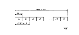
- FIG. 3 is a configuration diagram of a radio frame used in the LTE system.
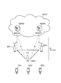
- FIG. 4 is a diagram for explaining the relay using the neighborhood service.
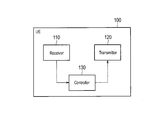
- FIG. 5 is a block diagram of the UE 100.
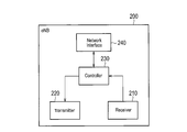
- FIG. 6 is a block diagram of the eNB 200.
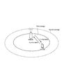
- FIG. 7 is a diagram for explaining the outline of the control operation (first control).
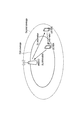
- FIG. 8 is a diagram for explaining the outline of the control operation (second control).
- FIG. 9 is a diagram for explaining the outline of the control operation (third control).
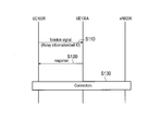
- FIG. 10 is a sequence diagram for explaining the determination operation according to the first embodiment.
- FIG. 11 is a sequence diagram for explaining the operation pattern 1.
- FIG. 12 is a sequence diagram for explaining the operation pattern 2.
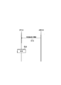
- FIG. 13 is a sequence diagram for explaining the operation of the second embodiment.
- the wireless terminal may include a control unit that executes any one of the first control, the second control, and the third control.
- the wireless terminal may directly send uplink information to be transmitted to a predetermined cell to the predetermined cell, and may directly receive downlink information to be received by the wireless terminal from the predetermined cell.
- the wireless terminal sends the uplink information to the predetermined cell via a relay terminal that performs relay using a neighbor service, and directly transmits the downlink information from the predetermined cell. You may receive it.
- the wireless terminal may send the uplink information to the predetermined cell via the relay terminal and receive the downlink information from the predetermined cell via the relay terminal.
- the control unit includes the first control, the second control, and the third control based on at least one of a reception level of a wireless signal from the predetermined cell and a transmission level of the wireless terminal. Any control may be executed.
- the control unit may receive information on a second determination criterion defined by at least one of the reception level and the transmission level from the predetermined cell.
- the second determination criterion may be used to determine an area where the second control can be performed.
- the control unit may execute the second control when the second determination criterion is satisfied and the first determination criterion for determining the coverage area of the predetermined cell is not satisfied.
- the control unit may execute the second control only when information on the second determination criterion is received from the predetermined cell.
- the control unit may receive information on transmission power applied when the second control is executed from the predetermined cell.
- the control unit may execute the second control when information on radio resources used for the relay is directly received from the predetermined cell.
- the control unit may transmit a side link signal in the proximity service before starting the second control.
- the side link signal may include information for notifying the relay terminal that the wireless terminal desires to relay only the uplink information.
- the control unit may transmit a side link signal in the proximity service before starting the second control.
- the side link signal may include an identifier of the predetermined cell that is a transmission source of the downlink information.
- the control unit may receive a side link signal in the proximity service before starting the second control.
- the side link signal may include an identifier of a cell in which another wireless terminal that is a transmission source of the side link signal is located.
- the control unit may determine that the second control is executable when the identifier of the cell indicates the predetermined cell.
- the control unit may determine that the second control is not executable when the identifier of the cell does not indicate the predetermined cell.
- the control unit may perform an operation for receiving the downlink information from the cell in which the other wireless terminal is located when the identifier of the cell does not indicate the predetermined cell.
- a first bearer for sending the uplink information to the predetermined cell via the relay terminal, and a second bearer for receiving the downlink information directly from the predetermined cell And may be established.
- the first bearer and the second bearer may be different.
- a wireless terminal includes a receiving unit that receives a side link signal for relay in a proximity service from a second terminal, and a control unit that determines whether the relay is executable. Also good. When the cell identifier included in the side link signal indicates a predetermined cell in which the wireless terminal is located, it may be determined that the relay is executable.
- the control unit may determine that the relay is not possible when the identifier of the cell does not indicate the predetermined cell.
- the control unit may start an operation for connecting to the cell indicated by the cell identifier when the cell identifier does not indicate the predetermined cell.
- the base station provides a reception level of a radio signal from the base station to a radio terminal that executes any one of the first control, the second control, and the third control. You may provide the transmission part which sends the information of the determination standard prescribed
- the base station may directly receive uplink information to be transmitted to the base station from the wireless terminal, and may directly transmit downlink information to be received by the wireless terminal to the wireless terminal.
- the base station receives the uplink information from the radio terminal via a relay terminal that performs relay using a proximity service, and directly transmits the downlink information to the radio terminal. You may send it.
- the base station may receive the uplink information from the wireless terminal via the relay terminal and send the downlink information to the wireless terminal via the relay terminal. .
- the determination criterion may be used to determine an area where the second control can be performed.
- the wireless terminal may include a control unit that executes any one of the first control and the second control.
- the wireless terminal may directly send uplink information to be transmitted to a predetermined cell to the predetermined cell, and may directly receive downlink information to be received by the wireless terminal from the predetermined cell.
- the wireless terminal sends the uplink information to the predetermined cell via a relay terminal that performs relay using a neighbor service, and directly transmits the downlink information from the predetermined cell. You may receive it.
- the control unit may execute the second control with priority over the first control.
- the control unit may preferentially execute the second control when receiving control information for preferentially executing the second control from the predetermined cell.
- the control unit may send information indicating that the wireless terminal prefers the second control to the predetermined cell.
- the base station may include a transmission unit that transmits control information to the wireless terminal so that the wireless terminal performs the second control preferentially over the first control.
- the base station may directly receive uplink information to be transmitted to the base station from the wireless terminal, and may directly transmit downlink information to be received by the wireless terminal to the wireless terminal.
- the base station receives the uplink information from the radio terminal via a relay terminal that performs relay using a proximity service, and directly transmits the downlink information to the radio terminal. You may send it.
- the base station may further include a receiving unit that receives information indicating that the wireless terminal prefers the second control from the wireless terminal or a network device.
- the transmission unit may transmit the control information to the wireless terminal in response to reception of the information.
- FIG. 1 is a diagram illustrating a configuration of an LTE system.
- the LTE system includes a UE (User Equipment) 100, an E-UTRAN (Evolved Universal Terrestrial Radio Access Network) 10, and an EPC (Evolved Packet Core) 20.
- UE User Equipment
- E-UTRAN Evolved Universal Terrestrial Radio Access Network
- EPC Evolved Packet Core
- the UE 100 corresponds to a communication device (wireless terminal).
- the UE 100 is a mobile communication device.
- UE100 performs radio
- the configuration of the UE 100 will be described later.
- the E-UTRAN 10 corresponds to a radio access network.
- the E-UTRAN 10 includes an eNB 200 (evolved Node-B).
- the eNB 200 corresponds to a base station.
- the eNB 200 is connected to each other via the X2 interface. The configuration of the eNB 200 will be described later.
- ENB 200 manages one or a plurality of cells.
- eNB200 performs radio
- the eNB 200 has a radio resource management (RRM) function, a routing function of user data (hereinafter also referred to as “data”), a measurement control function for mobility control / scheduling, and the like.
- RRM radio resource management
- Cell is used as a term indicating a minimum unit of a wireless communication area. “Cell” may also be used as a term indicating a function of performing wireless communication with the UE 100.
- the EPC 20 corresponds to a core network.
- the EPC 20 may form a network together with the E-UTRAN 10.
- the EPC 20 includes an MME (Mobility Management Entity) 300 and an SGW (Serving Gateway) 400.
- MME Mobility Management Entity
- SGW Serving Gateway
- the MME 300 performs various mobility controls for the UE 100, for example.
- the SGW 400 performs data transfer control.
- MME300 and SGW400 are connected with eNB200 via a S1 interface.
- FIG. 2 is a protocol stack diagram of a radio interface in the LTE system. As shown in FIG. 2, the radio interface protocol is divided into the first to third layers of the OSI reference model.
- the first layer is a physical (PHY) layer.
- the second layer includes a MAC (Medium Access Control) layer, an RLC (Radio Link Control) layer, and a PDCP (Packet Data Convergence Protocol) layer.
- the third layer includes an RRC (Radio Resource Control) layer.
- the physical layer performs encoding / decoding, modulation / demodulation, antenna mapping / demapping, and resource mapping / demapping.
- Data and control signals are transmitted between the physical layer of the UE 100 and the physical layer of the eNB 200 via a physical channel.
- the MAC layer performs data priority control, retransmission processing by hybrid ARQ (HARQ), random access procedure, and the like. Data and control signals are transmitted between the MAC layer of the UE 100 and the MAC layer of the eNB 200 via a transport channel.
- the MAC layer of the eNB 200 includes a scheduler (MAC scheduler). The scheduler determines the uplink / downlink transport format (transport block size, modulation / coding scheme (MCS)) and the resource blocks allocated to the UE 100.
- MCS modulation / coding scheme
- the RLC layer transmits data to the RLC layer on the receiving side using the functions of the MAC layer and the physical layer. Data and control signals are transmitted between the RLC layer of the UE 100 and the RLC layer of the eNB 200 via a logical channel.
- the PDCP layer performs header compression / decompression and encryption / decryption.
- the RRC layer is defined only in the control plane that handles control signals. Messages for various settings (RRC messages) are transmitted between the RRC layer of the UE 100 and the RRC layer of the eNB 200.
- the RRC layer controls the logical channel, the transport channel, and the physical channel according to establishment, re-establishment, and release of the radio bearer.
- RRC Radio Resource Control
- a NAS (Non-Access Stratum) layer located above the RRC layer performs, for example, session management and mobility management.
- FIG. 3 is a configuration diagram of a radio frame used in the LTE system.
- OFDMA Orthogonal Frequency Division Multiple Access
- SC-FDMA Single Carrier Frequency Division Multiple Access
- the radio frame is composed of 10 subframes arranged in the time direction.
- Each subframe is composed of two slots arranged in the time direction.
- the length of each subframe is 1 ms.
- the length of each slot is 0.5 ms.
- Each subframe includes a plurality of resource blocks (RB: Resource Block) in the frequency direction.
- Each subframe includes a plurality of symbols in the time direction.
- Each resource block includes a plurality of subcarriers in the frequency direction.
- One resource element (RE) is configured by one symbol and one subcarrier.
- a radio resource (time / frequency resource) is allocated to the UE 100.
- radio resources frequency resources
- radio resources are configured by resource blocks.
- radio resources (time resources) are configured by subframes (or slots).
- the section of the first several symbols of each subframe is an area that can be used as a physical downlink control channel (PDCCH: Physical Downlink. Control Channel) for transmitting a downlink control signal.
- the remaining part of each subframe is an area that can be used as a physical downlink shared channel (PDSCH) for transmitting downlink data.
- PDCH Physical Downlink control channel
- PDSCH physical downlink shared channel
- both ends in the frequency direction in each subframe are areas that can be used as physical uplink control channels (PUCCH: Physical Uplink Control Channels) for transmitting uplink control signals.
- PUCCH Physical Uplink Control Channels
- the remaining part of each subframe is an area that can be used as a physical uplink shared channel (PUSCH) for transmitting uplink data.
- PUSCH physical uplink shared channel
- the proximity service (ProSe: Proximity-based Services) will be described.
- the proximity service is a service that can be provided by the 3GPP system based on communication devices (for example, the UE 100) in the vicinity of each other.
- ProSe various radio signals are transmitted / received via a direct radio link between nodes (for example, between UEs) without going through the eNB 200.
- a direct radio link in ProSe is referred to as a “side link”.
- the side link may be an interface for side link communication and side link discovery (for example, an interface between the UE and the UE).
- the side link communication is a function (AS functionality) that enables ProSe direct communication (hereinafter referred to as “direct communication” as appropriate).
- Side link discovery is a function (AS functionality) that enables ProSe direct discovery (hereinafter referred to as “direct discovery” as appropriate).
- the side link corresponds to the PC5 interface.
- the PC 5 is a reference point among ProSe-usable UEs (ProSe-enabled UEs) used for a control plane and a user plane for ProSe direct discovery, ProSe direct communication and ProSe UE / network relay.
- ProSe-usable UEs ProSe-enabled UEs
- ProSe defines “Direct Discovery”, “Direct Communication”, and “Relay” modes. “Relay” will be described later.
- Direct discovery is a mode in which a partner is searched by directly transmitting a discovery message (discovery signal) that does not designate a specific destination between UEs.
- the direct discovery is a procedure for discovering another UE in the vicinity of the UE using a direct radio signal in E-UTRA (Evolved Universal Terrestrial Radio Access) via the PC 5.
- the direct discovery is a procedure adopted by the UE 100 capable of executing the proximity service in order to discover other UEs 100 capable of executing the proximity service using only the capability of the two UEs 100 with the E-UTRA technology.
- Direct discovery is supported only when UE 100 is served by E-UTRAN (eNB 200 (cell)). When the UE 100 is connected to the cell (eNB 200) or located in the cell, the UE 100 can be provided with service by the E-UTRAN.
- Type 1 There are “type 1” and “type 2 (type 2B)” as resource allocation types for transmission (announcement) of discovery messages (discovery signals).
- Type 1 the UE 100 selects a radio resource.
- UE100 may select a radio
- type 2 (type 2B) the eNB 200 allocates radio resources.
- the “Sidelink Direct Discovery” protocol stack includes a physical (PHY) layer, a MAC layer, and a ProSe protocol.
- a discovery signal is transmitted between a physical layer of UE (A) and a physical layer of UE (B) via a physical channel called a physical side link discovery channel (PSDCH).
- a discovery signal is transmitted between the MAC layer of UE (A) and the MAC layer of UE (B) via a transport channel called a side link discovery channel (SL-DCH).
- Direct communication is a mode in which data is directly transmitted between UEs by specifying a specific destination (destination group).
- Direct communication is communication between two or more UEs capable of performing proximity services by user plane transmission using E-UTRA technology via a path that does not pass through any network node.
- mode 1 There are “mode 1” and “mode 2” as resource allocation types for direct communication.
- the eNB 200 designates radio resources for direct communication.
- the UE 100 selects a radio resource for direct communication.
- UE100 may select a radio
- the direct communication protocol stack includes a physical (PHY) layer, a MAC layer, an RLC layer, and a PDCP layer.
- a control signal is transmitted via the physical side link control channel (PSCCH), and data is transmitted via the physical side link shared channel (PSSCH). Is transmitted.
- a synchronization signal or the like may be transmitted through a physical side link broadcast channel (PSBCH).
- PSBCH physical side link broadcast channel
- Data is transmitted between the MAC layer of UE (A) and the MAC layer of UE (B) via a transport channel called a side link shared channel (SL-SCH).
- SL-SCH side link shared channel
- STCH side link traffic channel
- FIG. 4 is a diagram for explaining the relay using the proximity service according to the embodiment.
- a remote UE is a UE 100 that communicates with a PDN (Packet Data Network) via a relay UE (ProSe UE-to-Network Relay).
- the remote UE may be a public safety (UE) for public safety (ProSe-enabled Public Safe UE).
- “ProSe-enabled Public Safety UE” is configured such that HPLMN (Home Public Land Mobile Network) authenticates the use for public safety.
- HPLMN Home Public Land Mobile Network
- “ProSe-enabled Public Safety UE” can use the neighborhood service and supports the procedure in the neighborhood service and specific capabilities for public safety. For example, “ProSe-enabled Public Safe UE” transmits information for public safety through a neighborhood service.
- the information for public safety is, for example, information on disasters (earthquakes, fires, etc.), information used for fire fighting personnel or police personnel, and the like.
- the remote UE may be a UE located outside the network range (Out-of-Network). That is, the remote UE may be located outside the cell coverage. The remote UE may be located within the coverage of the cell. Therefore, the remote UE may be a UE 100 that is not directly served by the E-UTRAN 10 (a UE 100 that is not served by the E-UTRAN 10).
- the remote UE is provided with a ProSe relay service from the relay UE, as will be described later. Relaying is performed between a remote UE that provides the ProSe relay service and a relay UE that provides the ProSe relay service.
- the Relay UE provides a function to support connectivity of “unicast” services for remote UEs. Therefore, the relay UE provides a ProSe relay service for the remote UE.
- the relay UE can relay data (unicast traffic) between the remote UE and the network.
- the relay UE can relay the data (traffic) of the remote UE by the proximity service (direct communication).
- the relay UE can relay data (upstream traffic) received from the remote UE via the PC5 interface to the eNB 200 via the Uu interface (LTE-Uu) or the Un interface (LTE-Un).
- the relay UE can relay data (downlink traffic) received from the eNB 200 via the Uu interface or Un interface to the remote UE via the PC5 interface.
- the relay UE may be located only in the network (within the coverage of the cell).
- the relay UE can provide a comprehensive function capable of relaying any type of traffic related to communication for public safety.
- the relay UE and the remote UE can transmit data and control signals between physical layers. Similarly, the relay UE and the remote UE can transmit data and control signals between the MAC layer, the RLC layer, and the PDCP layer.
- the relay UE may have an IP relay (IP-Relay) layer as an upper layer of the PDCP layer.
- the remote UE may have an IP layer as an upper layer of the PDCP layer.
- the relay UE and the remote UE can transmit data and control signals between the IP relay layer and the IP layer.
- the relay UE can transmit data between the IP relay layer and the IP layer of the PGW.
- a PGW Packet data Network Gateway
- a PGW Packet data Network Gateway
- the relay UE can transmit data (traffic) to the remote UE using broadcast in the AS layer (Access Stratum).
- the relay UE may transmit data to the remote UE using unicast in the AS layer.
- the ProSe relay service is performed using broadcast, feedback in the NAS layer (Non Access Stratum) may be performed between the relay UE and the remote UE without performing feedback in the AS layer.
- UE / network relay is performed using unicast, feedback in the AS layer may be performed.
- FIG. 5 is a block diagram of the UE 100. As illustrated in FIG. 5, the UE 100 includes a receiver (receiver) 110, a transmitter (transmitter) 120, and a controller (controller) 130.
- the receiver 110 and the transmitter 120 may be an integrated transceiver (transmission / reception unit).
- the receiver 110 performs various types of reception under the control of the controller 130.
- the receiver 110 includes an antenna.
- the receiver 110 converts a radio signal received by the antenna into a baseband signal (received signal).
- the receiver 110 outputs a baseband signal to the controller 130.
- the transmitter 120 performs various transmissions under the control of the controller 130.
- the transmitter 120 includes an antenna.
- the transmitter 120 converts the baseband signal (transmission signal) output from the controller 130 into a radio signal.
- the transmitter 130 transmits a radio signal from the antenna.
- the controller 130 performs various controls in the UE 100.
- the controller 130 includes a processor and a memory.
- the memory stores a program executed by the processor and information used for processing by the processor.
- the processor includes a baseband processor and a CPU (Central Processing Unit).
- the baseband processor performs, for example, modulation / demodulation and encoding / decoding of a baseband signal.
- the CPU performs various processes by executing programs stored in the memory.
- the processor may include a codec that performs encoding / decoding of an audio / video signal.
- the processor executes various processes described later and various communication protocols described above.
- the UE 100 may include a GNSS (Global Navigation Satellite System) receiver.
- the GNSS receiver can receive a GNSS signal in order to obtain location information indicating the geographical location of the UE 100.
- the GNSS receiver outputs a GNSS signal to the controller 130.
- the UE 100 may have a GPS (Global Positioning System) function for acquiring location information of the UE 100.
- a process executed by at least one of the receiver 110, the transmitter 120, and the controller 130 included in the UE 100 will be described as a process (operation) executed by the UE 100 for convenience.
- FIG. 6 is a block diagram of the eNB 200.
- the eNB 200 includes a receiver (reception unit) 210, a transmitter (transmission unit) 220, a controller (control unit) 230, and a network interface 240.
- the receiver 210 and the transmitter 220 may be an integrated transceiver (transmission / reception unit).
- the receiver 210 performs various types of reception under the control of the controller 230.
- the receiver 210 includes an antenna.
- the receiver 210 converts a radio signal received by the antenna into a baseband signal (received signal).
- the receiver 210 outputs a baseband signal to the controller 230.
- the transmitter 220 performs various transmissions under the control of the controller 230.
- the transmitter 220 includes an antenna.
- the transmitter 220 converts the baseband signal (transmission signal) output from the controller 230 into a radio signal.
- the transmitter 220 transmits a radio signal from the antenna.
- the controller 230 performs various controls in the eNB 200.
- the controller 230 includes a processor and a memory.
- the memory stores a program executed by the processor and information used for processing by the processor.
- the processor includes a baseband processor and a CPU.
- the baseband processor performs, for example, modulation / demodulation and encoding / decoding of a baseband signal.
- the CPU performs various processes by executing programs stored in the memory.
- the processor executes various processes described later and various communication protocols described above.
- the network interface 240 is connected to the neighboring eNB 200 via the X2 interface.
- the network interface 240 is connected to the MME 300 and the SGW 400 via the S1 interface.
- the network interface 240 is used for communication performed on the X2 interface and communication performed on the S1 interface, for example.
- a process executed by at least one of the transmitter 210, the receiver 220, the controller 230, and the network interface 240 included in the eNB 200 will be described as a process (operation) executed by the eNB 200 for convenience.
- FIGS. 7 to 9 are diagrams for explaining the outline of the control operation.
- the UE 100A directly transmits uplink information to be transmitted to the cell (eNB 200) to the cell (eNB 200). That is, in the first control, the eNB 200 directly receives uplink information from the UE 100A. Therefore, the UE 100A performs uplink transmission. The eNB 200 performs uplink reception.
- the uplink information is control information and / or user data from the eNB 200 to the UE 100A.
- Control information is carried via PUCCH.
- User data is carried via the PUSCH.
- the UE 100A directly receives the downlink information that the UE 100A should receive from the cell (eNB 200). That is, in the first control, the eNB 200 directly transmits downlink information to the UE 100A. Therefore, the UE 100A performs downlink reception. The eNB 200 performs downlink transmission.
- the downlink information is control information and / or user data from the UE 100A to the eNB 200.
- Control information is carried via PDCCH.
- User data is carried via the PDSCH.
- ProSe relay a proximity service
- the UE 100B sends uplink information to the cell via the UE 100A. That is, in the second control, the eNB 200 receives uplink information from the UE 100B via the UE 100A. Specifically, UE 100B sends uplink information to UE 100A. Therefore, the UE 100B performs side link transmission. The UE 100A performs side link reception. The UE 100A directly sends the uplink information received from the UE 100B to the eNB 200. Therefore, the UE 100A performs uplink transmission. The eNB 200 performs uplink reception. The UE 100A is a relay UE (ProSe UE-to-Network Relay).
- Uplink information is carried between the UE 100A and the eNB 200 in the same manner as in the first control described above.
- the control information of the uplink information may be carried via the PSCCH.
- Control information may be carried via the PSSCH.
- User data among uplink information may be carried via the PSSCH.
- the UE 100B directly receives downlink information from the cell (eNB 200). That is, in the second control, the eNB 200 directly transmits downlink information to the UE 100B.
- the reception (transmission) of downlink information is performed in the same manner as in the first control.
- Downlink information is carried in the same manner as in the first control described above.
- the UE 100B may transmit uplink information based on transmission power information applied when the second control is executed.
- the transmission power information may be a parameter in which the transmission power value in the second control is lower than the transmission power value in the first control.
- the transmission power information may be a parameter in which the transmission power value in the second control is lower than the transmission power value in the third control.
- the eNB 200 can send transmission power information to the UE 100B.
- UE100B can receive the information of transmission power from eNB200 (cell).
- the transmission power information may be included in determination criterion information to be described later.
- the UE 100C sends uplink information to the cell via the UE 100A. That is, in the third control, the eNB 200 receives uplink information from the UE 100C via the UE 100A. Transmission (reception) of uplink information is executed in the same manner as the second control.
- the UE 100C receives downlink information from the cell via the UE 100A. That is, in the third control, the eNB 200 sends downlink information to the UE 100C via the UE 100A. Specifically, the eNB 200 sends downlink information to the UE 100A. Accordingly, the eNB 200 performs downlink transmission. The UE 100A performs downlink reception. The UE 100A sends the downlink information received from the eNB 200 to the UE 100C. Therefore, the UE 100A performs side link transmission. The UE 100C performs side link reception.
- the downlink information is carried between the UE 100A and the eNB 200 in the same manner as in the first control described above.
- control information among downlink information may be carried via PSCCH.
- Control information may be carried via the PSSCH.
- User data among the downlink information may be carried via the PSSCH.
- FIG. 10 is a sequence diagram for explaining the determination operation according to the first embodiment.
- UE100 is based on at least one of the reception level of the radio signal from a cell (eNB200) and the transmission level of UE100, among 1st control, 2nd control, and 3rd control. Execute one of the controls.
- the reception level is based on a measurement result (measurement value) measured by the UE 100 for a radio signal from the cell (eNB 200).
- the reception level may be a value calculated from the measurement value (for example, “RS-SINR” described later).
- the transmission level may be, for example, the maximum power (value) defined based on the parameters set in the UE 100.
- the transmission level may be the maximum RF output power based on the UE power class.
- the transmission level may be a minimum power (value) defined based on a parameter set in the UE 100.
- the transmission level may be a transmission power (value) to be actually transmitted calculated based on a parameter set in the UE 100.
- the eNB 200 may send determination criterion information to the UE 100.
- the eNB 200 may individually notify the UE 100 of determination criterion information by unicast (for example, an RRC reconnection setup message).
- the eNB 200 may notify the UE 100A of determination criterion information by broadcast (for example, SIB: System Information Block).
- the information on the determination criterion may include a parameter relating to the first determination criterion (first threshold parameter (set)).
- the first determination criterion is used to determine an area where the first control can be performed.
- the first criterion is defined by at least one of the reception level of the radio signal (DL signal) from the cell (eNB 200) and the transmission level of the UE 100.
- the UE100 measures the reception level of the radio signal from a cell (eNB200). The UE 100 can determine whether or not the measurement result (reception level) satisfies the first determination criterion. The UE 100 can determine whether or not the transmission power value (transmission level) of the UE 100 satisfies the first determination criterion. The UE 100 can determine whether the reception level and the transmission level satisfy the first determination criterion.
- the first determination criterion may be, for example, a criterion related to DL signal received power (RSRP: Reference Signal Received Power).
- the first determination criterion may be a criterion related to DL signal reception quality (RSRQ: Reference Signal Received Quality).
- the first determination criterion may be RS-SINR (Reference Signal Signal Interference Noise Ratio) based on the DL signal.
- RS-SINR is the ratio (reference signal / interference signal) between the reference signal and the interference signal (interference noise).
- the first determination criterion may be, for example, a criterion regarding uplink transmission power.
- the first determination criterion may be, for example, a criterion regarding transmission power in the side link.
- the first criterion may be defined by both the reception level and the transmission level.
- the first determination criterion may be an S criterion (S-criteria) for determining a coverage area of a cell.
- the information on the determination criterion may include a parameter regarding the second determination criterion (second threshold parameter (set)).
- the second determination criterion is used to determine an area where the second control can be performed.
- the second determination criterion is defined by at least one of the DL signal reception level and the UE 100 transmission level.
- the UE 100 determines whether or not the measurement result (reception level) satisfies the second determination criterion.
- the second determination criterion is a criterion different from the S criterion.
- the second threshold parameter may be the same type of parameter as the first threshold parameter.
- the second threshold parameter may be a different type of parameter from the first threshold parameter.
- UE100 may hold
- step S20 the UE 100 determines which one of the first control, the second control, and the third control is to be executed.
- UE100 determines with the following method, for example.
- the UE 100 determines based on the information of the determination criterion.
- the UE 100 determines that the first control can be executed, for example, when the first determination criterion is satisfied. Therefore, the UE 100 determines that the first control can be executed when it is located within the first coverage based on the first determination criterion (see FIG. 7). The UE 100 determines that the first control is not executable when the UE 100 is located outside the first coverage based on the first determination criterion.
- the UE 100 determines that the first control can be executed.
- UE100 determines with 1st control being inexecutable, when RSRP of DL signal is less than a 1st threshold value.
- the UE 100 may determine that the first control cannot be performed when the uplink transmission power (uplink transmission power) is equal to or greater than the first threshold. When the uplink transmission power is less than the first threshold, the UE 100 may determine that the first control can be executed.
- uplink transmission power uplink transmission power
- the UE 100 determines that the second control can be executed, for example, when the second determination criterion is satisfied. Therefore, the UE 100 determines that the second control can be performed when the UE 100 is located within the second coverage (Second coverage) based on the second determination criterion (see FIG. 8). The UE 100 determines that the second control cannot be performed when the UE 100 is located outside the second coverage based on the second determination criterion.
- the UE 100 determines that the second control can be performed when the RSRP of the DL signal is equal to or greater than the second threshold.
- UE100 determines with 2nd control being inexecutable, when RSRP of DL signal is less than a 2nd threshold value.
- the UE 100 may determine that the second control can be performed when the uplink transmission power is equal to or greater than the second threshold.
- the UE 100 may determine that the second control cannot be executed when the uplink transmission power is less than the second threshold.
- the UE 100 may determine that the second control cannot be performed when the transmission power (SL transmission power) in the side link is equal to or greater than the second threshold.
- UE100 may determine with 2nd control being executable, when SL transmission power is less than a 2nd threshold value.
- the second threshold parameter may be set so that the second coverage is wider than the first coverage. Therefore, the second threshold value may be a lower value (or a larger value) than the first threshold value.
- the UE 100 may determine to execute the second control when the second determination criterion is satisfied and the first determination criterion is not satisfied. Therefore, even when the UE 100 satisfies the second determination criterion, the UE 100 may determine to execute the first control when the first determination criterion is satisfied.
- the UE 100 may determine that the UE 100 is located in the relay-extended coverage (relay-extended in-coverage) when the second determination criterion is satisfied and the relay UE exists in the vicinity. If the UE 100 is within the relay extended coverage, the UE 100 may determine to execute the second control. Even when the UE 100 satisfies the second determination criterion, the UE 100 may determine that the UE is located outside the coverage of the cell when the relay UE does not exist in the vicinity. In this case, the UE 100 determines to execute the third control.
- the UE 100 may determine that the second control can be performed only when the second determination criterion information (second threshold parameter) is received from the cell (eNB 200). That is, the information on the second determination criterion may be information suggesting permission of the eNB 200. Or eNB200 may transmit the permission information which shows explicitly permitting performing 2nd control to UE100. The UE 100 may determine that the eNB 200 is permitted to execute the second control in response to reception of the permission information.
- second threshold parameter the second determination criterion information
- the information on the second determination criterion may be information suggesting permission of the eNB 200.
- eNB200 may transmit the permission information which shows explicitly permitting performing 2nd control to UE100.
- the UE 100 may determine that the eNB 200 is permitted to execute the second control in response to reception of the permission information.
- the UE 100 may determine to execute the third control when the first determination criterion and the second determination criterion are not satisfied.
- the UE 100 determines to execute the second control when directly receiving information on radio resources used for ProSe relay from the cell (eNB 200).
- the UE 100 determines to execute the second control when, for example, the SIB (eg, the SIB 18 and / or SIB 19) including the radio resource information is successfully received.
- the UE 100 may determine to execute the second control when the S criterion is not satisfied and when the SIB is successfully received.
- the UE 100 can execute executable control among the first control, the second control, and the third control by the first method and / or the second method. As will be described later, the UE 100A may execute the second control preferentially over the first control.
- 1st control UE100 can perform the operation
- UL bearer uplink bearer
- DL bearer downlink bearer
- the UE100 does not need to establish RRC connection, when not transmitting uplink information to eNB200.
- the UE 100 may receive downlink information from the eNB 200 (cell) in the RRC idle state.
- (B) 2nd control UE100B can start the operation
- the UE 100B may start the operation when it is necessary to send uplink information to the eNB 200.
- the UE 100B may start the operation when transmission data is generated (for example, when transmission data is received from an upper layer).
- the UE 100B may start the operation when it is necessary to receive downlink information from the eNB 200.
- the UE 100B may start the operation when receiving a paging message from the base station.
- the UE 100B can execute one of the following operation patterns before starting the second control.
- FIG. 11 is a sequence diagram for explaining the operation pattern 1.
- the UE 100B transmits a side link signal.
- the side link signal may be a discovery signal or a communication signal.
- the discovery signal may be a signal that requires a response (solationation signal) or a signal that does not require a response.
- the side link signal may include relay information for notifying the relay UE that the UE 100B desires to relay only the uplink information.
- the relay information may be information indicating that the relay is only in one direction (Uni-direction: UL transmission).
- the relay information may be information indicating whether or not both uplink and downlink are desired.
- UE 100A may determine that UE 100B wants to relay only uplink information when the relay information indicates that both uplink and downlink are not desired.
- the side link signal may include an identifier of a cell that is a source of downlink information.
- the cell identifier may be information for designating the donor eNB (cell).
- the UE 100B may include the identifier of the cell that is the transmission source of the radio signal that satisfies the second determination criterion in the side link signal.
- the cell identifier may be a cell identifier of a control signal (for example, SIB). Therefore, the cell identifier may be an identifier of a cell that is permitted (set) to transmit / receive a side link signal.
- SIB control signal
- the UE 100 may be an identifier of the connection destination cell.
- the UE100A receives a side link signal.
- the UE 100A may grasp that the UE 100B desires to relay only the uplink information based on the relay information included in the side link signal.
- the UE 100A may determine whether or not the cell identifier included in the side link signal indicates a serving cell in which UE 100A is located.
- the serving cell is a cell to which the UE 100A is connected or a cell to which the UE 100A is camping.
- the UE 100A may determine that the ProSe relay can be performed when the cell identifier indicates the serving cell.
- the UE 100A may determine that the ProSe relay cannot be performed when the cell identifier does not indicate the serving cell.
- the UE 100A may start an operation for connecting to the cell indicated by the cell identifier when the cell identifier does not indicate the serving cell.
- the UE 100A may request the eNB to perform a handover for connecting to the cell indicated by the cell identifier.
- the UE 100A may determine that the ProSe relay is possible when the handover is successful. That is, the UE 100A may determine that ProSe relay is possible when the Uu connection is established with the cell indicated by the cell identifier.
- the UE 100A may start cell search when the identifier of the cell does not indicate a serving cell.
- the UE 100A may discover (select) the cell indicated by the cell identifier based on the cell search.
- the UE 100A finds the cell, the UE 100A may determine that the ProSe relay is possible.
- step S120 the UE 100A transmits a response to the side link signal (side link signal).
- the UE 100B receives a response to the side link signal.
- the UE 100A may transmit a response when the ProSe relay is executable. If the ProSe relay is not executable, the UE 100A may transmit a response indicating rejection.
- step S130 the UE 100A, the UE 100B, and the eNB 200 establish a connection.
- the UE 100A and UE 100B establish a connection for one-to-one communication.
- the UE 100A may initiate a connection for ProSe relay with the eNB 200.
- a bearer (UL bearer) for sending uplink information to the eNB 200 may be established.
- the UL bearer is a bearer that passes through the UE 100A.
- the UL bearer may be a bearer different from a bearer (DL bearer) for receiving downlink information from the eNB 200.
- the UL bearer and the DL bearer may be sub bearers.
- UL bearer and DL bearer may be mapped to the radio bearer between UE100B and eNB200.
- the UL bearer and the DL bearer may be mapped to an EPS bearer between the UE 100B and the PGW ((Packet Data Network Gateway)).
- PGW Packet Data Network Gateway
- the UE 100B can execute the second control.
- the UE 100B can match the cell (eNB 200) between the uplink information transmission destination and the downlink information transmission source. Thereby, the second operation can be executed without complicated control.
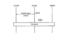
- FIG. 12 is a sequence diagram for explaining the operation pattern 2.
- the UE 100A transmits a side link signal.
- the side link signal is a discovery signal for discovering a remote UE.
- the side link signal may include an identifier of a cell in which the UE 100A that is the transmission source of the side link signal is located.
- the cell identifier may be information for designating the donor eNB (cell).
- UE 100B receives the side link signal.
- UE100B may start the process of step S220 according to reception of a side link signal.
- the UE 100B may determine that the second control is executable when the cell identifier indicates a cell (predetermined cell) that is a transmission source of downlink information. The UE 100B may determine that the second control is not executable when the cell identifier does not indicate a predetermined cell.
- the UE 100B may perform an operation for receiving downlink information from the serving cell of the UE 100A indicated by the cell identifier. That is, the UE 100B may switch the internal processing to receive downlink information from the serving cell indicated by the cell identifier. Therefore, the UE 100B may start a cell search for finding a serving cell indicated by the cell identifier.
- the UE 100 ⁇ / b> B may determine that the second control can be performed when the serving cell is found.
- the UE 100 ⁇ / b> B may determine that the second control is executable when the reception level of the radio signal from the located cell that has been found is equal to or higher than the threshold (for example, when the second determination criterion is satisfied). .
- the UE 100B may start the process of step S220 when the second control can be executed.
- the UE 100B may perform reception (or transmission) of a side link signal in order to discover a new relay UE located in a predetermined cell. Alternatively, the UE 100B may establish a connection (connection for one-for-one communication) for executing the existing ProSe relay with the UE 100A in order to execute the third control.
- Step S220 corresponds to step S130.
- (C) 3rd control UE100C can start operation
- the UE 100C does not need to include relay information in the side link signal.
- the UE 100C does not need to include the cell identifier in the side link signal.
- the UE 100C that has found the UE 100A as a relay UE establishes a connection for one-to-one communication with the UE 100A.
- UE100A starts the connection for ProSe relay with eNB200. Thereafter, the UE 100C can execute the third control.
- the UE 100B performs one of the first control, the second control, and the third control based on at least one of the reception level of the radio signal from the cell and the transmission level of the radio terminal. Control can be executed. For example, even when the S criterion is not satisfied, the UE 100B can execute the second control when the downlink information can be directly received from the eNB 200. Therefore, network coverage can be expanded (that is, coverage holes can be reduced).
- the UE 100A When the second control is executed, the UE 100A only needs to relay the uplink information, so the load of the relay processing of the UE 100A can be reduced. Even when the first control cannot be executed, the UE 100B can reduce the load of the relay process of the UE 100A by executing the second control instead of the third control.
- FIG. 13 is a sequence diagram for explaining the operation of the second embodiment.
- the UE 100 can send a notification (indication) indicating that the UE 100 prefers the second control to the eNB 200.
- the notification may be sent to the eNB 200 via a network device (for example, the MME 300).
- the UE 100 can send a notification to the network device.
- the UE 100 may send a notification to the eNB 200 when executing the power saving mode for reducing the power consumption.
- the UE 100 may send a notification to the eNB 200 when the remaining battery level falls below the threshold value.
- the notification may be information indicating that the UE 100 prefers power consumption reduction.
- the notification may be information indicating that the UE 100 is a communication device for machine type communication (MTC: Machine Type Communication) that is communication without human intervention.
- MTC Machine Type Communication
- the notification may be information indicating that the UE 100 is a wearable UE (a communication device that can be worn by the user).
- the notification may be information for requesting permission for the second control.
- the notification may be information indicating that the second control is executed (or is being executed).
- the eNB 200 may send setting information for executing the second control to the UE 100.
- the eNB 200 may send the setting information to the UE 100 in response to the notification from the UE 100.
- the setting information may include information indicating that execution of the second control is permitted.
- the setting information may include information on a determination criterion (second determination criterion) for determining whether or not the second control can be executed.
- the setting information may include control information for executing the second control with priority over the first control.
- step S330 the UE 100 starts the second control.
- the UE 100 may start the second control based on the setting information from the eNB 200.
- the UE 100 may execute the second control when the determination criterion (second determination criterion) is satisfied.
- the UE100 may perform 2nd control, without receiving the setting information from eNB200.
- the UE 100 can send information indicating that the second control is (or is being executed) to the eNB 200.
- the UE 100 may execute the second control preferentially over the first control. For example, when executing the power saving mode, the UE 100 may execute the second control with priority over the first control. The UE 100 may preferentially execute the second control over the first control when the battery remaining amount falls below the threshold value.
- the UE 100 may preferentially execute the second control over the first control based on the setting information. For example, when the setting information includes a threshold value that is compared with the remaining battery level, the UE 100 may execute the second control with priority over the first control when the remaining battery level falls below the threshold value. Good.
- the UE 100 can reduce the transmission power of the uplink information by performing the second control preferentially over the first control, it can reduce the power consumption.
- the UE 100 may determine executable control as follows.
- the UE 100 may determine the priority control based on the S criterion. For example, when the S standard in the standard coverage (normal coverage) is not satisfied and the S standard in the extended coverage (enhanced coverage) is satisfied, the UE 100 may execute the second control. That is, the UE 100 may prioritize the second control over the first control when the UE 100 is not located in the standard coverage but is located in the extended coverage. Alternatively, the UE 100 may prioritize the third control over the first control and the second control when the S criterion in the standard coverage is not satisfied and the S criterion in the extended coverage is satisfied. Good.
- the UE 100 may use a transmission level correction term (Pcompensation) set to 0 as the second determination criterion.
- Pcompensation transmission level correction term
- the S criterion is satisfied when the following expression (1) is satisfied.
- the extended coverage is a coverage defined for UE for MTC UE / NB-IoT (NarrowBand Internet of Things).
- the parameters are set so that the extended coverage is wider than the standard coverage.
- the criterion may be a criterion for detecting a radio link failure.
- the UE 100 may determine executable control using at least one of the determination value of out-of-synchronization time / number of times, the determination value of random access failure time / number of times, and the determination value of RLC retransmission failure number of times. Good.
- the UE 100 may determine to execute the first control when the criterion for detecting a radio link failure is not satisfied.
- the UE 100 may determine to execute the third control when the criterion for detecting the radio link failure is satisfied.
- the UE 100 satisfies a criterion for detecting a radio link failure (for example, at least one of a determination value of the random access failure time / number of times and a determination value of the number of RLC retransmission failures) and is based on the second determination criterion. It may be determined that the second control is to be executed when it is located within the second coverage.
- the eNB 200 may send only control information as downlink information. Therefore, in the second control, the eNB 200 directly sends only control information to the UE 100B. UE100B may receive only control information directly from eNB200 (cell). On the other hand, in the second control, the eNB 200 may send user data to the UE 100B via the UE 100A. The UE 100B may receive user data from the cell via the UE 100A.
- a program for causing a computer to execute each process performed by any of the above-described nodes may be provided.
- the program may be recorded on a computer readable medium. If a computer-readable medium is used, a program can be installed in the computer.
- the computer-readable medium on which the program is recorded may be a non-transitory recording medium.
- the non-transitory recording medium is not particularly limited, but may be a recording medium such as a CD-ROM or a DVD-ROM.
- a chip configured by a memory that stores a program for executing each process performed by either the UE 100 or the eNB 200 and a processor that executes the program stored in the memory may be provided.
- the LTE system has been described as an example of the mobile communication system, but the present invention is not limited to the LTE system, and the content according to the present application may be applied to a system other than the LTE system.
- the UE should consider itself in the extended coverage and the UE Applies the coverage eigenvalue Q rxlevmin_CE (dBm) as Q rxlevmin .
- the UE applies the coverage eigenvalue Q qualmin_CE (dB) as Q qualmin .
- the coverage eigenvalues Q rxlevmin_CE and Q qualmin_CE apply only for conformance checks in extended coverage (ie, not used for measurement and reselection thresholds).
- Srxlev is defined as a function of P PowerClass .
- Opinion 1 “In-coverage” assessment is affected by UE power class.
- a new UE power class i.e. class 5 with a maximum output power of 20 dBm
- the standard coverage may be 3 dB different between class 3 and class 5, and this coverage gap may be compensated by CE modes, ie, Q rxlevmin_CE and Q qualmin_CE .
Landscapes
- Engineering & Computer Science (AREA)
- Computer Networks & Wireless Communication (AREA)
- Signal Processing (AREA)
- Databases & Information Systems (AREA)
- Mobile Radio Communication Systems (AREA)
Abstract
Le terminal sans fil (unité de commande) d'après la présente invention exécute une première commande, une deuxième commande ou une troisième commande sur la base d'un niveau de réception de signaux sans fil provenant d'une cellule prescrite et/ou d'un niveau d'émission du terminal sans fil. Pendant la première commande, le terminal sans fil envoie directement à la cellule prescrite des informations de liaison montante devant être envoyées à la cellule prescrite et reçoit directement de la cellule prescrite des informations de liaison descendante devant être reçues par le terminal sans fil. Pendant la deuxième commande, le terminal sans fil envoie les informations de liaison montante à la cellule prescrite par l'intermédiaire d'un terminal de relais qui exécute un relais en utilisant un service de proximité et reçoit directement les informations de liaison descendante provenant de la cellule prescrite. Pendant la troisième commande, le terminal sans fil envoie les informations de liaison montante à la cellule prescrite par l'intermédiaire du terminal de relais et reçoit les informations de liaison descendante provenant de la cellule prescrite par l'intermédiaire du terminal de relais.
Priority Applications (2)
| Application Number | Priority Date | Filing Date | Title |
|---|---|---|---|
| JP2018517055A JP6773778B2 (ja) | 2016-05-13 | 2017-05-10 | 無線端末及び基地局 |
| US16/185,413 US10820372B2 (en) | 2016-05-13 | 2018-11-09 | Radio terminal and base station |
Applications Claiming Priority (2)
| Application Number | Priority Date | Filing Date | Title |
|---|---|---|---|
| US201662335913P | 2016-05-13 | 2016-05-13 | |
| US62/335,913 | 2016-05-13 |
Related Child Applications (1)
| Application Number | Title | Priority Date | Filing Date |
|---|---|---|---|
| US16/185,413 Continuation US10820372B2 (en) | 2016-05-13 | 2018-11-09 | Radio terminal and base station |
Publications (1)
| Publication Number | Publication Date |
|---|---|
| WO2017195824A1 true WO2017195824A1 (fr) | 2017-11-16 |
Family
ID=60266672
Family Applications (1)
| Application Number | Title | Priority Date | Filing Date |
|---|---|---|---|
| PCT/JP2017/017688 Ceased WO2017195824A1 (fr) | 2016-05-13 | 2017-05-10 | Terminal sans fil et station de base |
Country Status (3)
| Country | Link |
|---|---|
| US (1) | US10820372B2 (fr) |
| JP (1) | JP6773778B2 (fr) |
| WO (1) | WO2017195824A1 (fr) |
Cited By (2)
| Publication number | Priority date | Publication date | Assignee | Title |
|---|---|---|---|---|
| JP2023509936A (ja) * | 2020-01-07 | 2023-03-10 | エルジー エレクトロニクス インコーポレイティド | 無線通信システムにおいて端末が信号を送受信する方法 |
| JP2024522159A (ja) * | 2021-06-08 | 2024-06-11 | コーニンクレッカ フィリップス エヌ ヴェ | 2次局を動作させるための方法 |
Families Citing this family (5)
| Publication number | Priority date | Publication date | Assignee | Title |
|---|---|---|---|---|
| US11418998B2 (en) * | 2018-04-17 | 2022-08-16 | Telefonaktiebolaget Lm Ericsson (Publ) | Wireless device, network node, core node and methods for handling radio communication of data |
| US10841772B2 (en) * | 2018-12-28 | 2020-11-17 | Wipro Limited | Method and system for controlling communication between internet-of-things (IOT) devices |
| US11792771B2 (en) * | 2020-10-23 | 2023-10-17 | Qualcomm Incorporated | Transport block forwarding over different air interfaces |
| US11553543B2 (en) * | 2021-02-03 | 2023-01-10 | Qualcomm Incorporated | Link combining and component carrier selection across sidelink and access link interfaces |
| WO2022203575A1 (fr) * | 2021-03-23 | 2022-09-29 | Telefonaktiebolaget Lm Ericsson (Publ) | Sélection de cellule d'équipement utilisateur (ue) de liaison latérale (sl) lors d'une transition hors couverture et d'une transition en cours de couverture |
Citations (2)
| Publication number | Priority date | Publication date | Assignee | Title |
|---|---|---|---|---|
| US20140233454A1 (en) * | 2013-02-15 | 2014-08-21 | General Dynamics Broadband Inc. | Communication Units and Methods for Relay-Assisted Uplink Communication |
| JP2014522619A (ja) * | 2011-06-14 | 2014-09-04 | エスシーエー アイピーエルエー ホールディングス インコーポレイテッド | 無線通信システム及び方法 |
Family Cites Families (6)
| Publication number | Priority date | Publication date | Assignee | Title |
|---|---|---|---|---|
| US8050360B2 (en) * | 2002-06-12 | 2011-11-01 | Intellectual Ventures I Llc | Direct link relay in a wireless network |
| EP2245885B1 (fr) * | 2008-01-22 | 2012-11-28 | Research In Motion Limited | Sélection de trajet pour un système sans fil avec relais |
| US20140171062A1 (en) * | 2012-12-19 | 2014-06-19 | Telefonaktiebolaget L M Ericsson (Publ) | Wireless Devices, Network Node and Methods for Handling Relay Assistance in a Wireless Communications Network |
| WO2015015234A1 (fr) * | 2013-07-30 | 2015-02-05 | Sony Corporation | Procédé de demande d'activation d'une fonction de répéteur et équipement utilisateur |
| US9826460B2 (en) * | 2015-05-14 | 2017-11-21 | Qualcomm Incorporated | Measurement of D2D channels |
| WO2017028013A1 (fr) * | 2015-08-14 | 2017-02-23 | 富士通株式会社 | Procédé, dispositif et système pour sélection de relais |
-
2017
- 2017-05-10 WO PCT/JP2017/017688 patent/WO2017195824A1/fr not_active Ceased
- 2017-05-10 JP JP2018517055A patent/JP6773778B2/ja active Active
-
2018
- 2018-11-09 US US16/185,413 patent/US10820372B2/en active Active
Patent Citations (2)
| Publication number | Priority date | Publication date | Assignee | Title |
|---|---|---|---|---|
| JP2014522619A (ja) * | 2011-06-14 | 2014-09-04 | エスシーエー アイピーエルエー ホールディングス インコーポレイテッド | 無線通信システム及び方法 |
| US20140233454A1 (en) * | 2013-02-15 | 2014-08-21 | General Dynamics Broadband Inc. | Communication Units and Methods for Relay-Assisted Uplink Communication |
Cited By (3)
| Publication number | Priority date | Publication date | Assignee | Title |
|---|---|---|---|---|
| JP2023509936A (ja) * | 2020-01-07 | 2023-03-10 | エルジー エレクトロニクス インコーポレイティド | 無線通信システムにおいて端末が信号を送受信する方法 |
| JP7338066B2 (ja) | 2020-01-07 | 2023-09-04 | エルジー エレクトロニクス インコーポレイティド | 無線通信システムにおいて端末が信号を送受信する方法 |
| JP2024522159A (ja) * | 2021-06-08 | 2024-06-11 | コーニンクレッカ フィリップス エヌ ヴェ | 2次局を動作させるための方法 |
Also Published As
| Publication number | Publication date |
|---|---|
| JP6773778B2 (ja) | 2020-10-21 |
| US10820372B2 (en) | 2020-10-27 |
| US20190098697A1 (en) | 2019-03-28 |
| JPWO2017195824A1 (ja) | 2019-03-07 |
Similar Documents
| Publication | Publication Date | Title |
|---|---|---|
| JP6773650B2 (ja) | 基地局及び無線端末 | |
| JP6586512B2 (ja) | 通信方法及び通信装置 | |
| JP6174213B2 (ja) | ユーザ端末、プロセッサ及び基地局 | |
| JP6641038B2 (ja) | ユーザ装置、基地局、及び方法 | |
| JP6773778B2 (ja) | 無線端末及び基地局 | |
| WO2017138378A1 (fr) | Terminal sans fil | |
| JP6670929B2 (ja) | 無線端末及び基地局 | |
| JP6554613B2 (ja) | 通信装置 | |
| JPWO2014129356A1 (ja) | 移動通信システム、基地局、ユーザ端末及びプロセッサ | |
| WO2017026409A1 (fr) | Terminal sans fil | |
| WO2017130743A1 (fr) | Terminal sans fil, appareil de communication et station de base | |
| WO2018061760A1 (fr) | Terminal radio et dispositif de réseau | |
| US20180255610A1 (en) | Radio terminal, processor, and network device | |
| WO2017051859A1 (fr) | Terminal sans fil | |
| JP6615729B2 (ja) | 通信方法、ユーザ端末及びプロセッサ | |
| JP6298218B2 (ja) | 通信方法、無線端末、プロセッサ及び基地局 | |
| JP6239270B2 (ja) | 基地局、ユーザ端末及びプロセッサ | |
| JPWO2018155236A1 (ja) | 無線通信装置及びプロセッサ | |
| JP6382429B2 (ja) | 基地局、ユーザ端末、プロセッサ、及び方法 | |
| JP2025508355A (ja) | NRリレー-多重経路(multipath)WTRU-NWリレー間のシステム情報取得方法 | |
| WO2016021701A1 (fr) | Station de base et terminal utilisateur |
Legal Events
| Date | Code | Title | Description |
|---|---|---|---|
| ENP | Entry into the national phase |
Ref document number: 2018517055 Country of ref document: JP Kind code of ref document: A |
|
| NENP | Non-entry into the national phase |
Ref country code: DE |
|
| 121 | Ep: the epo has been informed by wipo that ep was designated in this application |
Ref document number: 17796184 Country of ref document: EP Kind code of ref document: A1 |
|
| 122 | Ep: pct application non-entry in european phase |
Ref document number: 17796184 Country of ref document: EP Kind code of ref document: A1 |