WO2017195860A1 - Dispositif et procédé de commande de niveau de mobilité - Google Patents
Dispositif et procédé de commande de niveau de mobilité Download PDFInfo
- Publication number
- WO2017195860A1 WO2017195860A1 PCT/JP2017/017807 JP2017017807W WO2017195860A1 WO 2017195860 A1 WO2017195860 A1 WO 2017195860A1 JP 2017017807 W JP2017017807 W JP 2017017807W WO 2017195860 A1 WO2017195860 A1 WO 2017195860A1
- Authority
- WO
- WIPO (PCT)
- Prior art keywords
- mobility level
- mobility
- level
- user device
- movement
- Prior art date
- Legal status (The legal status is an assumption and is not a legal conclusion. Google has not performed a legal analysis and makes no representation as to the accuracy of the status listed.)
- Ceased
Links
Images

Classifications
-
- H—ELECTRICITY
- H04—ELECTRIC COMMUNICATION TECHNIQUE
- H04W—WIRELESS COMMUNICATION NETWORKS
- H04W88/00—Devices specially adapted for wireless communication networks, e.g. terminals, base stations or access point devices
- H04W88/18—Service support devices; Network management devices
-
- H—ELECTRICITY
- H04—ELECTRIC COMMUNICATION TECHNIQUE
- H04W—WIRELESS COMMUNICATION NETWORKS
- H04W88/00—Devices specially adapted for wireless communication networks, e.g. terminals, base stations or access point devices
- H04W88/18—Service support devices; Network management devices
- H04W88/184—Messaging devices, e.g. message centre
-
- H—ELECTRICITY
- H04—ELECTRIC COMMUNICATION TECHNIQUE
- H04W—WIRELESS COMMUNICATION NETWORKS
- H04W64/00—Locating users or terminals or network equipment for network management purposes, e.g. mobility management
- H04W64/006—Locating users or terminals or network equipment for network management purposes, e.g. mobility management with additional information processing, e.g. for direction or speed determination
-
- H—ELECTRICITY
- H04—ELECTRIC COMMUNICATION TECHNIQUE
- H04W—WIRELESS COMMUNICATION NETWORKS
- H04W68/00—User notification, e.g. alerting and paging, for incoming communication, change of service or the like
- H04W68/02—Arrangements for increasing efficiency of notification or paging channel
-
- H—ELECTRICITY
- H04—ELECTRIC COMMUNICATION TECHNIQUE
- H04W—WIRELESS COMMUNICATION NETWORKS
- H04W68/00—User notification, e.g. alerting and paging, for incoming communication, change of service or the like
- H04W68/04—User notification, e.g. alerting and paging, for incoming communication, change of service or the like multi-step notification using statistical or historical mobility data
-
- H—ELECTRICITY
- H04—ELECTRIC COMMUNICATION TECHNIQUE
- H04W—WIRELESS COMMUNICATION NETWORKS
- H04W8/00—Network data management
- H04W8/02—Processing of mobility data, e.g. registration information at HLR [Home Location Register] or VLR [Visitor Location Register]; Transfer of mobility data, e.g. between HLR, VLR or external networks
- H04W8/08—Mobility data transfer
-
- H—ELECTRICITY
- H04—ELECTRIC COMMUNICATION TECHNIQUE
- H04W—WIRELESS COMMUNICATION NETWORKS
- H04W8/00—Network data management
- H04W8/26—Network addressing or numbering for mobility support
-
- H—ELECTRICITY
- H04—ELECTRIC COMMUNICATION TECHNIQUE
- H04W—WIRELESS COMMUNICATION NETWORKS
- H04W60/00—Affiliation to network, e.g. registration; Terminating affiliation with the network, e.g. de-registration
- H04W60/04—Affiliation to network, e.g. registration; Terminating affiliation with the network, e.g. de-registration using triggered events
Definitions
- the present invention relates to a mobility level control apparatus and a mobility level control method for controlling the mobility level of a user apparatus in an idle state.
- LTE including LTE-Advanced LTE-Advanced
- LTE Long Term Evolution
- 5G 5th generation mobile mobile communication systems
- Non-Patent Document 1 it is assumed that more types of user devices such as a user device for Internet Things (IoT) and a user device for non-IoT are used. Therefore, it has been studied to define a plurality of user device mobility levels in the idle state (for example, Non-Patent Document 1). As a result, it is possible to simultaneously reduce the management load on the user apparatus and improve the service quality.
- IoT Internet Things
- non-IoT non-IoT
- the user is selected from a plurality of mobility levels ranging from a mobility level having a low movement frequency (or degree of movement, the same applies hereinafter) to a mobility level having a high movement frequency. It is under consideration to set the device to any mobility level.
- the above-described mobility level setting for the user apparatus has the following problems.
- any mobility level is fixedly set for each user apparatus, when the movement state of the user apparatus, that is, when the mobility level changes, it is already set for the user apparatus. There may be cases where it does not match the existing mobility level.
- a mobility level with a low movement frequency is generally set. Thereafter, in order to use the user device for other purposes, the user device may move frequently when installed in a vehicle or the like. Therefore, at the mobility level where the movement frequency is low, there is a possibility that the service quality required for the user apparatus cannot be secured.
- the present invention has been made in view of such circumstances, and a mobility level control apparatus and a mobility that can select an appropriate mobility level even when the mobility level of a user apparatus in an idle state changes dynamically.
- the purpose is to provide a level control method.
- One aspect of the present invention is a mobility level control apparatus (ME300) that controls a mobility level (IMM) of the user apparatus in an idle state according to a movement state of the user apparatus (UE100), and the movement of the user apparatus Based on the movement state of the user apparatus acquired by the movement state acquisition unit (movement state acquisition unit 320) for acquiring the state and the movement state acquisition unit, any one of the mobility levels is selected from the plurality of mobility levels.
- a mobility level selection unit (mobility level selection unit 330) to select, and a mobility level notification unit (mobility level notification unit 340) that notifies the user device of the mobility level selected by the mobility level selection unit.
- One aspect of the present invention is a mobility level control method in a control device that controls a mobility level of the user device in an idle state in accordance with a moving state of the user device, wherein the control device is in a moving state of the user device. And selecting one of the plurality of mobility levels from the plurality of mobility levels, and the control device notifying the user device of the selected mobility level.
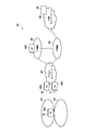
- FIG. 1 is an overall schematic configuration diagram of a wireless communication system 10.
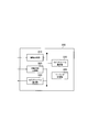
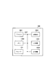
- FIG. 2 is a functional block configuration diagram of ME300.
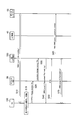
- FIG. 3 is a diagram showing a communication sequence associated with a change in mobility level (level 1 to level 3) set in UE 100.
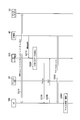
- FIG. 4 is a diagram showing a communication sequence associated with a change in mobility level (level 3 to level 1) set in UE 100.
- FIG. 5 is a diagram illustrating a communication sequence associated with paging for the UE 100.
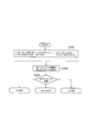
- FIG. 6 is a diagram showing a mobility level selection flow by the ME 300.
- FIG. 7 is a diagram illustrating an example of a hardware configuration of the ME 300.
- FIG. 1 is an overall schematic configuration diagram of a radio communication system 10 according to the present embodiment.
- the radio communication system 10 is a radio communication system according to “5G” which is a successor system of Long Term Evolution (LTE).
- LTE Long Term Evolution
- the radio communication system 10 may be called FRA (Future Radio Access) or next-generation system (NextGen).
- the radio communication system 10 includes a radio access network 20, a core network control plane function 30 (hereinafter, CP function 30), a core network user plane function 40 (hereinafter, UP function 40), and a user device 100 ( Hereinafter, UE100) is included. Further, an external network 50 is connected to the wireless communication system 10, specifically, the UP function 40.
- CP function 30 core network control plane function 30
- UP function 40 core network user plane function 40
- UE100 user device 100
- an external network 50 is connected to the wireless communication system 10, specifically, the UP function 40.
- the radio access network 20 is a radio network according to radio access technology (RAT) defined in, for example, the 3rd Generation Partnership Project (3GPP), and includes a radio base station 200 (hereinafter, BS 200).
- RAT radio access technology
- 3GPP 3rd Generation Partnership Project
- the CP function 30 and the UP function 40 are connected to the radio access network 20.
- the CP function 30 and the UP function 40 provide a control plane function and a user plane function in the core network of the wireless communication system 10. That is, in the core network of the radio communication system 10, the control plane function that realizes control of the UE 100 and BS 200 and the user plane function that realizes transmission and reception of user data are clearly separated (CUPS: C / U plane separation) is adopted.
- the CP function 30 and the UP function 40 are respectively configured by Serving Gateway (SGW), PDN Gateway (PGW), Traffic Detection Function (TDF), and the like.
- SGW Serving Gateway
- PGW PDN Gateway
- TDF Traffic Detection Function
- External network 50 is connected to UP function 40.
- a typical example of the external network 50 is the Internet, but the type of the external network 50 is not particularly limited, and may be a private network provided by an operator of the wireless communication system 10 or the like.
- the external network 50 is provided with a data repository 55.
- the data repository 55 stores data (such as an IMM level described later) transmitted from the UE 100.
- UE100 and BS200 execute wireless communication according to the wireless communication technology specified in 3GPP.
- the type of UE 100 is not particularly limited.
- UE 100 may be a user device for Internet of Things (IoT), for example, MTC (Machine Type Communication), or may be a user device for non-IoT such as a conventional smartphone.
- IoT Internet of Things
- MTC Machine Type Communication
- the UE 100 may change the movement frequency or the degree of movement according to the type and use as described above.
- the movement frequency is the number of times the UE 100 moves within a predetermined time, and is not related to the distance moved.
- the degree of movement is typically the distance moved within a predetermined time.
- a unit that can determine the degree of geographical movement such as a tracking area (TA) described later, may be used instead of the distance.
- TA tracking area
- the movement state of the UE 100 may change from a state where it does not move at all to a state where it moves at high speed, depending on the type and use as described above.
- a plurality of mobility levels are defined according to the movement state of the UE 100, and any one of the mobility levels is selected from the plurality of mobility levels according to the movement state of the UE 100 that dynamically changes. .
- the mobility control entity 300 (hereinafter, ME300) is one of the devices that constitute the CP function 30.
- the ME 300 constitutes a mobility level control device.
- ME 300 controls the mobility level of UE 100 in the idle state according to the movement state of UE 100.
- the UE 100 In the idle state, the UE 100 is connected to the core network configured by the CP function 30 and the UP function 40, but the active user plane path (user data path, user data bearer or connection, etc.) It means a state that does not have.
- the UE 100 in the idle state can change its moving state according to the type and usage as described above.
- the ME 300 can appropriately update the mobility level of UE 100 by controlling the mobility level in the idle state of UE 100.
- the ME 300 can control the mobility level of the UE 100 when the UE 100 establishes a packet data connection (PDN Connection).
- PDN Connection packet data connection
- IMM Idle Mode Mobility
- ME300 dynamically selects an optimal mobility level corresponding to the movement state of UE100. Moreover, ME300 can periodically acquire the movement state of UE100, and can update the mobility level of UE100 based on the latest movement state of UE100. In consideration of the functions provided by the ME 300, the ME 300 may be referred to as On Demand Management Entity.
- Fig. 2 is a functional block diagram of ME300. As illustrated in FIG. 2, the ME 300 includes an information acquisition unit 310, a movement state acquisition unit 320, a mobility level selection unit 330, a mobility level notification unit 340, and a paging processing unit 350.
- the information acquisition unit 310 acquires information (user information) related to the UE 100 connected to the radio access network 20, specifically, the attached UE 100.
- User information indicates at least one of the attribute or state of UE100.
- the attribute indicates the characteristics or properties of the UE 100, and is provided in advance for the UE 100 or is required for the UE 100 in advance. For example, the type of UE 100, required quality of service (QoS), delay time (Latency), and the like can be given.
- QoS quality of service
- Latency delay time
- the state indicates the state or circumstances of the UE 100, and may change depending on the usage state of the UE 100 and the like. For example, the traffic pattern of the data which UE100 transmits / receives is mentioned.
- the type of the core network provided by the radio access network 20 to which the UE 100 is connected (attached) and the UP function 40 is included in the state of the UE 100.
- the movement state acquisition unit 320 acquires the movement state of the UE 100.
- the movement state is the movement frequency or the degree of movement of the UE 100 as described above.
- the movement state acquisition unit 320 can acquire the presence / absence of movement (Location change) of the UE 100 and the timing at which the UE 100 has moved. More specifically, the movement state acquisition unit 320 acquires the location change reported from the UE 100 and the time information when the location change occurred. Note that the timing at which the location change has occurred is not necessarily time information, and may be indicated by an elapsed time based on a predetermined time point.
- the movement state acquisition unit 320 can acquire whether or not the UE 100 has moved from a predetermined unit area to another unit area. Specifically, the movement state acquisition unit 320 acquires whether or not the UE 100 has moved from the tracking area (TA) where the UE 100 is located to another tracking area.
- TA tracking area
- the tracking area is a unit area that includes one or a plurality of cells and indicates the position of the UE 100 managed on the core network.
- the mobility level selection unit 330 selects any one of the mobility levels as the mobility level associated with the UE 100. Specifically, mobility level selection section 330 selects any one of a plurality of mobility levels based on the movement state of UE 100 acquired by movement state acquisition section 320.
- level 0 to level 3 are defined as mobility levels (IMM) in the idle state of UE 100.
- level 0 does not have an idle state (Idle Mode)
- levels 1 to 3 are targeted as mobility levels in the idle state.
- Level 1 (No mobility) cannot track UE100 from the core network and cannot reach UE100 when UE100 transitions to the idle state.
- the UE 100 can maintain the PDN Connection for a certain period of time in order to enable paging from the core network. This enables data transmission to UE 100 in the idle state.
- Level 2 (Limited mobility) is applied when UE100 stays within a specific TA (Fixed TA). In the case of level 2, UE100 does not need to transmit TAU (TA Update) periodically.
- Level 3 (Full mobility) is applied when UE100 moves across multiple TAs.
- UE 100 transmits TAU (TA Update) to the core network (CP function 30).
- TAU TA Update
- the mobility level selection unit 330 can select an appropriate mobility level at that time according to the moving state of the UE 100 that can change with the passage of time. That is, the mobility level selection unit 330 can dynamically change the mobility level set for the UE 100.
- the mobility level selection unit 330 can select a mobility level based on the presence or absence of movement of the UE 100 acquired by the movement state acquisition unit 320 and the timing of movement. For example, the mobility level selection unit 330 sets the mobility level (any one of levels 1 to 3) corresponding to the movement frequency (for example, one movement / time) of the UE 100 calculated based on the presence / absence and timing of the movement. select.
- the mobility level selection unit 330 can select the mobility level based on the UE 100 moving from a specific TA (predetermined unit area) to another TA (other unit area). Specifically, when the UE 100 moves to a different TA, for example, when the UE 100 moves from the tracking area A1 to the tracking area A2 shown in FIG. ) Is selected.
- the mobility level selection unit 330 can also select a mobility level based on the movement state of the UE 100 and the user information acquired by the information acquisition unit 310.
- the mobility level selection unit 330 can select a mobility level based on the type of UE 100 (eMBB (enhanced mobile broadband), MTC (Machine Type Communication), etc.) in addition to the movement state of UE100.
- the mobility level selection unit 330 basically selects a mobility level (level 1) with a low movement frequency by default, and moves the UE 100 movement frequency or degree of movement.
- Other mobility levels (such as level 2) can be selected only when becomes higher.
- the mobility level notification unit 340 notifies the UE 100 of the mobility level set for the UE 100. Specifically, the mobility level notification unit 340 notifies the UE 100 of the mobility level selected by the mobility level selection unit 330 and inquires whether the UE 100 supports the selected mobility level.
- control channel or a shared data channel can be used for notification to the UE 100 of the selected mobility level.
- the paging processing unit 350 executes processing related to paging for the UE 100. Specifically, the paging processing unit 350 receives a paging request from the CP function 30, and transmits a paging signal to the UE 100 based on the paging request.
- FIGS. 3 and 4 show a communication sequence that accompanies a change in mobility level set in the UE 100. Specifically, FIG. 3 shows a communication sequence for changing the IMM from level 1 to level 3, and FIG. 4 shows a communication sequence for changing the IMM from level 3 to level 1.
- FIG. 5 shows a communication sequence associated with paging for the UE 100.
- UE 100 connected to the temperature sensor is initially installed on an indoor wall surface, and a low mobility level (level 1) is set for UE 100. Then, in order to use UE100 for other purposes, UE100 is installed in a vehicle that moves at high speed, and a high mobility level (level 3) is set for UE100. Furthermore, the vehicle in which the UE 100 is installed stops for a certain time, and a low mobility level (level 1) is set for the UE 100 again.
- Mobility level change (from level 1 to level 3) As shown in FIG. 3, UE100 is installed on an indoor wall surface, and a low mobility level (level 1) is set for UE100 (S10). Further, after the mobility level is set, the UE 100 transmits data (for example, the set IMM level) to the data repository 55.
- data for example, the set IMM level
- the selection of level 1 may be based on the user device for IoT (MTC) in which UE 100 is connected to the temperature sensor, that is, the type of user device, or the movement state of UE 100 is monitored over a predetermined time. It may be based on the result.
- MTC user device for IoT
- UE100 is installed in a vehicle that moves at high speed.
- the UE 100 recovers from the hibernation state at a predetermined timing (Wake up), and detects that it is moving (S15).
- UE 100 notifies ME 300 that it has moved over the tracking area (TA) (Location change across TA) via wireless access network 20 (S20, S30).
- Location change across TA may include the fact that it has moved and the identifiers (cell IDs) of the cells constituting the TA.
- ME300 selects level 3 as the mobility level of UE 100 as the movement state of UE 100 changes.
- the ME 300 notifies the UE 100 of level 3 and inquires whether the selected level is supported (S40).
- the UE 100 returns an acknowledgment (ACK) indicating that the IMM level 3 is supported (S50).
- ACK acknowledgment
- the ME 300 reports to the data repository 55 that the IMM level set for the UE 100 has been changed to level 3 and that the position of the UE 100 has moved (S60).
- the data repository 55 stores the information reported from the ME300. Such information is useful for grasping the movement frequency at which the UE 100 straddles the TA.
- a high mobility level (level 3) is set for the UE 100, and the UE 100 is tracked by the core network (ME300) (S70).
- Mobility level change (from level 3 to level 1) As shown in FIG. 4, the UE 100 is continuously set to a high mobility level (level 3), and the UE 100 transmits data (such as the set IMM level) to the data repository 55 (S110).
- data such as the set IMM level
- the vehicle in which the UE 100 is installed stops for a certain time, and the ME 300 detects that the UE 100 has not moved for a certain time or more (S120).
- the ME 300 can detect that the UE 100 has not moved for a certain time or longer by periodically acquiring information indicating the position of the UE 100.
- the information indicating the position of the UE 100 may be a cell ID, position information indicating more specific longitude and latitude, or GPS (Global Positioning System) information.
- ME300 selects level 1 as the mobility level of UE 100 as the movement state of UE 100 changes.
- ME 300 notifies UE 100 of level 1 and inquires whether the selected level is supported (S130).
- the UE 100 returns an acknowledgment (ACK) indicating that the IMM level 1 is supported (S140).
- ACK acknowledgment
- ME300 reports to the data repository 55 that the IMM level set in UE100 has been changed to level 1 (S150).
- a low mobility level (level 1) is set for the UE 100, and the UE 100 is managed by the core network (ME300) (S160).
- the mobility level of level 2 or level 3 is set for the UE 100, and the UE 100 sets the data (set to the data repository 55). IMM level etc.). (S210).
- the mobility level of the UE 100 is level 1, when the UE 100 is in an idle state, the UE 100 cannot be tracked and cannot reach the UE 100.
- UP function 40 transmits an incoming call notification indicating that data addressed to UE 100 exists to ME 300 (S215).
- ME 300 detects that data addressed to UE 100 (incoming data) has occurred based on the incoming notification (S220). Specifically, the CP function 30 is notified when the incoming data reaches the UP function 40. ME 300 detects that data addressed to UE 100 has occurred based on such an incoming call notification (S220).
- ME 300 transmits a paging signal to UE 100 when data addressed to UE 100 is generated (S230).
- the UE 100 returns an acknowledgment (ACK) for paging (S240).
- ACK acknowledgment
- UE 100 sets a connection (PDN Connection) necessary for data reception based on paging, and executes data reception (and transmission) via UP function 40 (S250).
- PDN Connection a connection necessary for data reception based on paging
- UP function 40 UP function 40
- UE 100 transitions to an idle state when a predetermined time has elapsed after the reception (and transmission) of the data is completed (S260).
- FIG. 6 shows a mobility level selection flow by the ME 300. Specifically, FIG. 6 shows a mobility level selection operation flow in step S40 of FIG. 3 and S130 of FIG. 4 described above.
- the ME 300 acquires information (user information) indicating the type of the UE 100 and information related to movement of the UE 100 (S310). Specifically, the ME 300 acquires the following information.
- UE type eMBB (enhanced mobile broadband), MTC (Machine Type Communication)
- Presence or absence of UE100 movement Lication change
- timing time stamp
- ⁇ subscription based> means based on a contract with a network operator
- ⁇ motion / mobility based> means based on the movement state of UE100.
- ME 300 determines parameters used for selecting the mobility level based on the acquired information (S320). Specifically, ME 300 selects a parameter to be used for selecting a mobility level from among parameters constituting a plurality of pieces of information as described above. The number of parameters to be selected may be single or plural.
- ME 300 selects a mobility level based on the content (value) of the selected parameter (S330). Specifically, ME 300 selects one of the following as the IMM.
- No mobility No IMM
- Level 1 Limited mobility (Limited IMM)
- Level 2 Full mobility (Full IMM) (Level 3)
- ME 300 selects an appropriate mobility level according to the movement state from a plurality of mobility levels (level 1 to level 3) based on the movement state of UE 100.
- ME 300 can appropriately select an appropriate mobility level according to the moving state of UE 100 that can change. Further, by appropriately selecting a mobility level with a low movement frequency, it is possible to achieve both a reduction in the management load of the UE 100 and an improvement in service quality at a higher level.
- the ME 300 can select a mobility level based on the presence / absence of movement of the UE 100 (Location change) and the timing at which the UE 100 moves (time stamp). For this reason, when the movement state of UE100 changes, an appropriate mobility level can be selected quickly and reliably.
- the ME 300 can select the mobility level based on whether or not the UE 100 has moved from the tracking area (TA) where the UE 100 is located to another tracking area. For this reason, even when the UE 100 makes a significant movement across the TA, an appropriate mobility level can be selected quickly and reliably.
- TA tracking area
- the ME 300 can select a mobility level based on user information such as the type of the UE 100 as well as the movement state of the UE 100. For this reason, it can contribute to selection of the more substantial mobility level which considered the characteristic (for example, user apparatus for MTC with a low mobility level).
- each functional block is realized by one device physically and / or logically coupled, and two or more devices physically and / or logically separated may be directly and / or indirectly. (For example, wired and / or wireless) and may be realized by the plurality of devices.
- FIG. 7 is a diagram illustrating an example of a hardware configuration of the ME 300.
- the ME 300 may be configured as a computer device including a processor 1001, a memory 1002, a storage 1003, a communication device 1004, an input device 1005, an output device 1006, a bus 1007, and the like.
- the processor 1001 controls the entire computer by operating an operating system, for example.
- the processor 1001 may be configured by a central processing unit (CPU) including an interface with peripheral devices, a control device, an arithmetic device, a register, and the like.
- CPU central processing unit
- the memory 1002 is a computer-readable recording medium such as a ROM (Read It may be configured by at least one of only memory (EPROM), erasable programmable ROM (EPROM), electrically erasable programmable ROM (EEPROM), random access memory (RAM), and the like.
- the memory 1002 may be called a register, a cache, a main memory (main storage device), or the like.
- the memory 1002 can store programs (program codes), software modules, and the like that can execute the methods according to the above-described embodiments.
- the storage 1003 is a computer-readable recording medium such as an optical disc such as a CD-ROM (Compact Disc ROM), a hard disk drive, a flexible disc, a magneto-optical disc (eg a compact disc, a digital versatile disc, a Blu-ray). (Registered trademark) disk, smart card, flash memory (for example, card, stick, key drive), floppy (registered trademark) disk, magnetic strip, and the like.
- the storage 1003 may be referred to as an auxiliary storage device.
- the above-described storage medium may be, for example, a database, a server, or other suitable medium including the memory 1002 and / or the storage 1003.
- the communication device 1004 is hardware (transmission / reception device) for performing communication between computers via a wired and / or wireless network, and is also referred to as a network device, a network controller, a network card, a communication module, or the like.
- the input device 1005 is an input device (for example, a keyboard, a mouse, a microphone, a switch, a button, a sensor, etc.) that accepts input from the outside.
- the output device 1006 is an output device (for example, a display, a speaker, an LED lamp, or the like) that performs output to the outside. Note that the input device 1005 and the output device 1006 may have an integrated configuration (for example, a touch panel).
- each device such as the processor 1001 and the memory 1002 is connected by a bus 1007 for communicating information.
- the bus 1007 may be configured with a single bus or may be configured with different buses between apparatuses.
- notification of information includes physical layer signaling (eg, DCI (Downlink Control Information), UCI (Uplink Control Information)), upper layer signaling (eg, RRC signaling, MAC (Medium Access Control) signaling, broadcast information (MIB ( Master (Information Block), SIB (System Information Block)), other signals, or combinations thereof, and RRC signaling may also be referred to as RRC messages, eg, RRC Connection Connection message, RRC It may be a Connection ⁇ ⁇ Reconfiguration message.
- RRC messages eg, RRC Connection Connection message, RRC It may be a Connection ⁇ ⁇ Reconfiguration message.
- input / output information may be stored in a specific location (for example, a memory) or may be managed by a management table.
- the input / output information can be overwritten, updated, or appended.
- the output information may be deleted.
- the input information may be transmitted to other devices.
- the specific operation performed by the ME 300 may be performed by another network node (device).
- the function of ME 300 may be provided by a combination of a plurality of other network nodes.
- the function of the paging processing unit 350 may be implemented in another device that constitutes the CP function 30.
- the channel and / or symbol may be a signal.
- the signal may be a message.
- system and “network” may be used interchangeably.
- the parameters described above may be represented by absolute values, may be represented by relative values from predetermined values, or may be represented by other corresponding information.
- the radio resource may be indicated by an index.
- BS 200 can accommodate one or a plurality of (for example, three) cells (also called sectors).
- a base station accommodates multiple cells, the entire coverage area of the base station can be partitioned into multiple smaller areas, each smaller area being a base station subsystem (eg, indoor small base station RRH: Remote Radio Head) can also provide communication services.
- RRH Remote Radio Head
- cell refers to part or all of the coverage area of a base station and / or base station subsystem that provides communication services in this coverage.
- base station eNB
- cell ector
- a base station may also be referred to in terms such as a fixed station (fixed station), NodeB, eNodeB (eNB), access point (access point), femto cell, small cell, and the like.
- UE100 is a subscriber station, mobile unit, subscriber unit, wireless unit, remote unit, mobile device, wireless device, wireless communication device, remote device, mobile subscriber station, access terminal, mobile terminal, wireless terminal by those skilled in the art , Remote terminal, handset, user agent, mobile client, client, or some other appropriate terminology.
- the phrase “based on” does not mean “based only on”, unless expressly specified otherwise. In other words, the phrase “based on” means both “based only on” and “based at least on.”
- an appropriate mobility level can be selected even when the mobility level of the user device in the idle state changes dynamically.
- Wireless communication system 20
- Wireless access network 30
- CP function 40
- UP function 50
- External network 55
- Data repository 100
- UE 200 BS 300
- ME Information acquisition unit
- Movement state acquisition unit 330
- Mobility level selection unit 340
- Mobility level notification unit 350
- Paging processing unit 1001
- Processor 1002
- Memory 1003
- Storage 1004
- Communication device 1005
- Input device 1006
- Output device 1007 Bus A1, A2 Tracking area
Landscapes
- Engineering & Computer Science (AREA)
- Computer Networks & Wireless Communication (AREA)
- Signal Processing (AREA)
- Databases & Information Systems (AREA)
- Physics & Mathematics (AREA)
- Probability & Statistics with Applications (AREA)
- Mobile Radio Communication Systems (AREA)
Abstract
L'invention concerne un dispositif et un procédé de commande de niveau de mobilité qui permettent de sélectionner un niveau de mobilité approprié même lorsque le niveau de mobilité d'un dispositif utilisateur inactif change de manière dynamique. Un ME (300) commande le niveau de mobilité (IMM) du dispositif utilisateur inactif en fonction de l'état de déplacement du dispositif utilisateur. Le ME (300) comprend : une unité d'acquisition d'état de déplacement (320) conçue pour obtenir l'état de déplacement du dispositif utilisateur ; une unité de sélection de niveau de mobilité (330) conçue pour sélectionner un niveau de mobilité parmi une pluralité de niveaux de mobilité sur la base de l'état de déplacement du dispositif utilisateur obtenu par l'unité d'acquisition d'état de déplacement (320) ; et une unité de notification de niveau de mobilité (340) conçue pour notifier au dispositif utilisateur le niveau de mobilité sélectionné par l'unité de sélection de niveau de mobilité (330).
Priority Applications (3)
| Application Number | Priority Date | Filing Date | Title |
|---|---|---|---|
| JP2018517074A JP7122253B2 (ja) | 2016-05-13 | 2017-05-11 | モビリティレベル制御装置及びモビリティレベル制御方法 |
| CN201780029658.7A CN109155981A (zh) | 2016-05-13 | 2017-05-11 | 移动性等级控制装置以及移动性等级控制方法 |
| US16/300,106 US11723117B2 (en) | 2016-05-13 | 2017-05-11 | Mobility level control device and mobility level control method |
Applications Claiming Priority (2)
| Application Number | Priority Date | Filing Date | Title |
|---|---|---|---|
| JP2016097251 | 2016-05-13 | ||
| JP2016-097251 | 2016-05-13 |
Publications (1)
| Publication Number | Publication Date |
|---|---|
| WO2017195860A1 true WO2017195860A1 (fr) | 2017-11-16 |
Family
ID=60266528
Family Applications (1)
| Application Number | Title | Priority Date | Filing Date |
|---|---|---|---|
| PCT/JP2017/017807 Ceased WO2017195860A1 (fr) | 2016-05-13 | 2017-05-11 | Dispositif et procédé de commande de niveau de mobilité |
Country Status (4)
| Country | Link |
|---|---|
| US (1) | US11723117B2 (fr) |
| JP (1) | JP7122253B2 (fr) |
| CN (1) | CN109155981A (fr) |
| WO (1) | WO2017195860A1 (fr) |
Families Citing this family (1)
| Publication number | Priority date | Publication date | Assignee | Title |
|---|---|---|---|---|
| US11864050B2 (en) * | 2021-08-04 | 2024-01-02 | GM Global Technology Operations LLC | Radio access network notification area selection and paging based on travel information |
Citations (2)
| Publication number | Priority date | Publication date | Assignee | Title |
|---|---|---|---|---|
| WO2014013660A1 (fr) * | 2012-07-20 | 2014-01-23 | 日本電気株式会社 | Dispositif de télé-avertissement, procédé de télé-avertissement, terminal sans fil et support lisible par ordinateur non temporaire |
| JP2014023017A (ja) * | 2012-07-20 | 2014-02-03 | Sharp Corp | 移動局装置、基地局装置、通信システム、通信方法および集積回路 |
Family Cites Families (1)
| Publication number | Priority date | Publication date | Assignee | Title |
|---|---|---|---|---|
| WO2016009579A1 (fr) | 2014-07-14 | 2016-01-21 | 日本電気株式会社 | Procédé et dispositif de gestion de la mobilité |
-
2017
- 2017-05-11 CN CN201780029658.7A patent/CN109155981A/zh active Pending
- 2017-05-11 JP JP2018517074A patent/JP7122253B2/ja active Active
- 2017-05-11 US US16/300,106 patent/US11723117B2/en active Active
- 2017-05-11 WO PCT/JP2017/017807 patent/WO2017195860A1/fr not_active Ceased
Patent Citations (2)
| Publication number | Priority date | Publication date | Assignee | Title |
|---|---|---|---|---|
| WO2014013660A1 (fr) * | 2012-07-20 | 2014-01-23 | 日本電気株式会社 | Dispositif de télé-avertissement, procédé de télé-avertissement, terminal sans fil et support lisible par ordinateur non temporaire |
| JP2014023017A (ja) * | 2012-07-20 | 2014-02-03 | Sharp Corp | 移動局装置、基地局装置、通信システム、通信方法および集積回路 |
Non-Patent Citations (1)
| Title |
|---|
| NOKIA: "Solution: Mobility Options", 3GPP TSG-SA WG2#114 S 2-161625, 15 April 2016 (2016-04-15), XP051086598, Retrieved from the Internet <URL:http://www.3gpp.org/ftp/tsg_sa/WG2_Arch/TSGS2_114_Sophia_Antipolis/Docs/S2-161625.zip> * |
Also Published As
| Publication number | Publication date |
|---|---|
| JPWO2017195860A1 (ja) | 2019-03-14 |
| CN109155981A (zh) | 2019-01-04 |
| US20190150226A1 (en) | 2019-05-16 |
| JP7122253B2 (ja) | 2022-08-19 |
| US11723117B2 (en) | 2023-08-08 |
Similar Documents
| Publication | Publication Date | Title |
|---|---|---|
| US9480045B2 (en) | Networks and methods for paging message control | |
| CN104956703B (zh) | 网络级设备邻近度检测 | |
| CN110999440B (zh) | 无线基站及无线通信方法 | |
| CN101981986A (zh) | 避免无线终端反复期间的过多信令 | |
| JP2009077368A (ja) | 無線通信端末装置、無線通信基地局装置及び無線通信方法 | |
| WO2018068752A1 (fr) | Procédé et appareil de détermination de zone de radiomessagerie | |
| WO2018036455A1 (fr) | Procédé et appareil de détermination de zone de radiomessagerie | |
| CN110463296A (zh) | 用于在跨越多种无线电接入技术的区域中寻呼用户设备的方法和装置 | |
| WO2016095113A1 (fr) | Procédé de radiomessagerie, entité de gestion de mobilité, et station de base | |
| US9191911B2 (en) | Tracking registration buffer in a cellular network | |
| WO2017185199A1 (fr) | Procédé de fixation et appareil, procédé de pagination et dispositif | |
| WO2016163112A1 (fr) | Dispositif et procédé d'optimisation de radiomessagerie | |
| KR101584839B1 (ko) | 상이한 무선 기술의 인접 셀의 시그널링에 대한 연속적인 검색 사이의 시간 간격 증가 | |
| CN113170412B (zh) | 基于传播信道特性延迟网络中用户设备寻呼操作的系统、方法和计算机程序产品 | |
| WO2016165385A1 (fr) | Procédé de contrôle d'accès, nœud de communications et support d'informations pour ordinateur | |
| JP7122253B2 (ja) | モビリティレベル制御装置及びモビリティレベル制御方法 | |
| JP7300538B2 (ja) | アンカーポイント制御装置及びアンカーポイント制御方法 | |
| KR20190052465A (ko) | 페이징 처리 장치 및 방법 | |
| JP2019033432A (ja) | 移動管理エンティティ及び無線通信方法 | |
| CN121486910A (zh) | 一种移动性管理方法、装置及可读存储介质 | |
| WO2014047945A1 (fr) | Procédé et appareil d'accès à un équipement utilisateur |
Legal Events
| Date | Code | Title | Description |
|---|---|---|---|
| ENP | Entry into the national phase |
Ref document number: 2018517074 Country of ref document: JP Kind code of ref document: A |
|
| NENP | Non-entry into the national phase |
Ref country code: DE |
|
| 121 | Ep: the epo has been informed by wipo that ep was designated in this application |
Ref document number: 17796218 Country of ref document: EP Kind code of ref document: A1 |
|
| 122 | Ep: pct application non-entry in european phase |
Ref document number: 17796218 Country of ref document: EP Kind code of ref document: A1 |