WO2017195860A1 - モビリティレベル制御装置及びモビリティレベル制御方法 - Google Patents
モビリティレベル制御装置及びモビリティレベル制御方法 Download PDFInfo
- Publication number
- WO2017195860A1 WO2017195860A1 PCT/JP2017/017807 JP2017017807W WO2017195860A1 WO 2017195860 A1 WO2017195860 A1 WO 2017195860A1 JP 2017017807 W JP2017017807 W JP 2017017807W WO 2017195860 A1 WO2017195860 A1 WO 2017195860A1
- Authority
- WO
- WIPO (PCT)
- Prior art keywords
- mobility level
- mobility
- level
- user device
- movement
- Prior art date
- Legal status (The legal status is an assumption and is not a legal conclusion. Google has not performed a legal analysis and makes no representation as to the accuracy of the status listed.)
- Ceased
Links
Images

Classifications
-
- H—ELECTRICITY
- H04—ELECTRIC COMMUNICATION TECHNIQUE
- H04W—WIRELESS COMMUNICATION NETWORKS
- H04W88/00—Devices specially adapted for wireless communication networks, e.g. terminals, base stations or access point devices
- H04W88/18—Service support devices; Network management devices
-
- H—ELECTRICITY
- H04—ELECTRIC COMMUNICATION TECHNIQUE
- H04W—WIRELESS COMMUNICATION NETWORKS
- H04W88/00—Devices specially adapted for wireless communication networks, e.g. terminals, base stations or access point devices
- H04W88/18—Service support devices; Network management devices
- H04W88/184—Messaging devices, e.g. message centre
-
- H—ELECTRICITY
- H04—ELECTRIC COMMUNICATION TECHNIQUE
- H04W—WIRELESS COMMUNICATION NETWORKS
- H04W64/00—Locating users or terminals or network equipment for network management purposes, e.g. mobility management
- H04W64/006—Locating users or terminals or network equipment for network management purposes, e.g. mobility management with additional information processing, e.g. for direction or speed determination
-
- H—ELECTRICITY
- H04—ELECTRIC COMMUNICATION TECHNIQUE
- H04W—WIRELESS COMMUNICATION NETWORKS
- H04W68/00—User notification, e.g. alerting and paging, for incoming communication, change of service or the like
- H04W68/02—Arrangements for increasing efficiency of notification or paging channel
-
- H—ELECTRICITY
- H04—ELECTRIC COMMUNICATION TECHNIQUE
- H04W—WIRELESS COMMUNICATION NETWORKS
- H04W68/00—User notification, e.g. alerting and paging, for incoming communication, change of service or the like
- H04W68/04—User notification, e.g. alerting and paging, for incoming communication, change of service or the like multi-step notification using statistical or historical mobility data
-
- H—ELECTRICITY
- H04—ELECTRIC COMMUNICATION TECHNIQUE
- H04W—WIRELESS COMMUNICATION NETWORKS
- H04W8/00—Network data management
- H04W8/02—Processing of mobility data, e.g. registration information at HLR [Home Location Register] or VLR [Visitor Location Register]; Transfer of mobility data, e.g. between HLR, VLR or external networks
- H04W8/08—Mobility data transfer
-
- H—ELECTRICITY
- H04—ELECTRIC COMMUNICATION TECHNIQUE
- H04W—WIRELESS COMMUNICATION NETWORKS
- H04W8/00—Network data management
- H04W8/26—Network addressing or numbering for mobility support
-
- H—ELECTRICITY
- H04—ELECTRIC COMMUNICATION TECHNIQUE
- H04W—WIRELESS COMMUNICATION NETWORKS
- H04W60/00—Affiliation to network, e.g. registration; Terminating affiliation with the network, e.g. de-registration
- H04W60/04—Affiliation to network, e.g. registration; Terminating affiliation with the network, e.g. de-registration using triggered events
Definitions
- the present invention relates to a mobility level control apparatus and a mobility level control method for controlling the mobility level of a user apparatus in an idle state.
- LTE including LTE-Advanced LTE-Advanced
- LTE Long Term Evolution
- 5G 5th generation mobile mobile communication systems
- Non-Patent Document 1 it is assumed that more types of user devices such as a user device for Internet Things (IoT) and a user device for non-IoT are used. Therefore, it has been studied to define a plurality of user device mobility levels in the idle state (for example, Non-Patent Document 1). As a result, it is possible to simultaneously reduce the management load on the user apparatus and improve the service quality.
- IoT Internet Things
- non-IoT non-IoT
- the user is selected from a plurality of mobility levels ranging from a mobility level having a low movement frequency (or degree of movement, the same applies hereinafter) to a mobility level having a high movement frequency. It is under consideration to set the device to any mobility level.
- the above-described mobility level setting for the user apparatus has the following problems.
- any mobility level is fixedly set for each user apparatus, when the movement state of the user apparatus, that is, when the mobility level changes, it is already set for the user apparatus. There may be cases where it does not match the existing mobility level.
- a mobility level with a low movement frequency is generally set. Thereafter, in order to use the user device for other purposes, the user device may move frequently when installed in a vehicle or the like. Therefore, at the mobility level where the movement frequency is low, there is a possibility that the service quality required for the user apparatus cannot be secured.
- the present invention has been made in view of such circumstances, and a mobility level control apparatus and a mobility that can select an appropriate mobility level even when the mobility level of a user apparatus in an idle state changes dynamically.
- the purpose is to provide a level control method.
- One aspect of the present invention is a mobility level control apparatus (ME300) that controls a mobility level (IMM) of the user apparatus in an idle state according to a movement state of the user apparatus (UE100), and the movement of the user apparatus Based on the movement state of the user apparatus acquired by the movement state acquisition unit (movement state acquisition unit 320) for acquiring the state and the movement state acquisition unit, any one of the mobility levels is selected from the plurality of mobility levels.
- a mobility level selection unit (mobility level selection unit 330) to select, and a mobility level notification unit (mobility level notification unit 340) that notifies the user device of the mobility level selected by the mobility level selection unit.
- One aspect of the present invention is a mobility level control method in a control device that controls a mobility level of the user device in an idle state in accordance with a moving state of the user device, wherein the control device is in a moving state of the user device. And selecting one of the plurality of mobility levels from the plurality of mobility levels, and the control device notifying the user device of the selected mobility level.
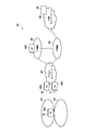
- FIG. 1 is an overall schematic configuration diagram of a wireless communication system 10.
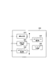
- FIG. 2 is a functional block configuration diagram of ME300.
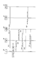
- FIG. 3 is a diagram showing a communication sequence associated with a change in mobility level (level 1 to level 3) set in UE 100.
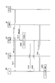
- FIG. 4 is a diagram showing a communication sequence associated with a change in mobility level (level 3 to level 1) set in UE 100.
- FIG. 5 is a diagram illustrating a communication sequence associated with paging for the UE 100.
- FIG. 6 is a diagram showing a mobility level selection flow by the ME 300.
- FIG. 7 is a diagram illustrating an example of a hardware configuration of the ME 300.
- FIG. 1 is an overall schematic configuration diagram of a radio communication system 10 according to the present embodiment.
- the radio communication system 10 is a radio communication system according to “5G” which is a successor system of Long Term Evolution (LTE).
- LTE Long Term Evolution
- the radio communication system 10 may be called FRA (Future Radio Access) or next-generation system (NextGen).
- the radio communication system 10 includes a radio access network 20, a core network control plane function 30 (hereinafter, CP function 30), a core network user plane function 40 (hereinafter, UP function 40), and a user device 100 ( Hereinafter, UE100) is included. Further, an external network 50 is connected to the wireless communication system 10, specifically, the UP function 40.
- CP function 30 core network control plane function 30
- UP function 40 core network user plane function 40
- UE100 user device 100
- an external network 50 is connected to the wireless communication system 10, specifically, the UP function 40.
- the radio access network 20 is a radio network according to radio access technology (RAT) defined in, for example, the 3rd Generation Partnership Project (3GPP), and includes a radio base station 200 (hereinafter, BS 200).
- RAT radio access technology
- 3GPP 3rd Generation Partnership Project
- the CP function 30 and the UP function 40 are connected to the radio access network 20.
- the CP function 30 and the UP function 40 provide a control plane function and a user plane function in the core network of the wireless communication system 10. That is, in the core network of the radio communication system 10, the control plane function that realizes control of the UE 100 and BS 200 and the user plane function that realizes transmission and reception of user data are clearly separated (CUPS: C / U plane separation) is adopted.
- the CP function 30 and the UP function 40 are respectively configured by Serving Gateway (SGW), PDN Gateway (PGW), Traffic Detection Function (TDF), and the like.
- SGW Serving Gateway
- PGW PDN Gateway
- TDF Traffic Detection Function
- External network 50 is connected to UP function 40.
- a typical example of the external network 50 is the Internet, but the type of the external network 50 is not particularly limited, and may be a private network provided by an operator of the wireless communication system 10 or the like.
- the external network 50 is provided with a data repository 55.
- the data repository 55 stores data (such as an IMM level described later) transmitted from the UE 100.
- UE100 and BS200 execute wireless communication according to the wireless communication technology specified in 3GPP.
- the type of UE 100 is not particularly limited.
- UE 100 may be a user device for Internet of Things (IoT), for example, MTC (Machine Type Communication), or may be a user device for non-IoT such as a conventional smartphone.
- IoT Internet of Things
- MTC Machine Type Communication
- the UE 100 may change the movement frequency or the degree of movement according to the type and use as described above.
- the movement frequency is the number of times the UE 100 moves within a predetermined time, and is not related to the distance moved.
- the degree of movement is typically the distance moved within a predetermined time.
- a unit that can determine the degree of geographical movement such as a tracking area (TA) described later, may be used instead of the distance.
- TA tracking area
- the movement state of the UE 100 may change from a state where it does not move at all to a state where it moves at high speed, depending on the type and use as described above.
- a plurality of mobility levels are defined according to the movement state of the UE 100, and any one of the mobility levels is selected from the plurality of mobility levels according to the movement state of the UE 100 that dynamically changes. .
- the mobility control entity 300 (hereinafter, ME300) is one of the devices that constitute the CP function 30.
- the ME 300 constitutes a mobility level control device.
- ME 300 controls the mobility level of UE 100 in the idle state according to the movement state of UE 100.
- the UE 100 In the idle state, the UE 100 is connected to the core network configured by the CP function 30 and the UP function 40, but the active user plane path (user data path, user data bearer or connection, etc.) It means a state that does not have.
- the UE 100 in the idle state can change its moving state according to the type and usage as described above.
- the ME 300 can appropriately update the mobility level of UE 100 by controlling the mobility level in the idle state of UE 100.
- the ME 300 can control the mobility level of the UE 100 when the UE 100 establishes a packet data connection (PDN Connection).
- PDN Connection packet data connection
- IMM Idle Mode Mobility
- ME300 dynamically selects an optimal mobility level corresponding to the movement state of UE100. Moreover, ME300 can periodically acquire the movement state of UE100, and can update the mobility level of UE100 based on the latest movement state of UE100. In consideration of the functions provided by the ME 300, the ME 300 may be referred to as On Demand Management Entity.
- Fig. 2 is a functional block diagram of ME300. As illustrated in FIG. 2, the ME 300 includes an information acquisition unit 310, a movement state acquisition unit 320, a mobility level selection unit 330, a mobility level notification unit 340, and a paging processing unit 350.
- the information acquisition unit 310 acquires information (user information) related to the UE 100 connected to the radio access network 20, specifically, the attached UE 100.
- User information indicates at least one of the attribute or state of UE100.
- the attribute indicates the characteristics or properties of the UE 100, and is provided in advance for the UE 100 or is required for the UE 100 in advance. For example, the type of UE 100, required quality of service (QoS), delay time (Latency), and the like can be given.
- QoS quality of service
- Latency delay time
- the state indicates the state or circumstances of the UE 100, and may change depending on the usage state of the UE 100 and the like. For example, the traffic pattern of the data which UE100 transmits / receives is mentioned.
- the type of the core network provided by the radio access network 20 to which the UE 100 is connected (attached) and the UP function 40 is included in the state of the UE 100.
- the movement state acquisition unit 320 acquires the movement state of the UE 100.
- the movement state is the movement frequency or the degree of movement of the UE 100 as described above.
- the movement state acquisition unit 320 can acquire the presence / absence of movement (Location change) of the UE 100 and the timing at which the UE 100 has moved. More specifically, the movement state acquisition unit 320 acquires the location change reported from the UE 100 and the time information when the location change occurred. Note that the timing at which the location change has occurred is not necessarily time information, and may be indicated by an elapsed time based on a predetermined time point.
- the movement state acquisition unit 320 can acquire whether or not the UE 100 has moved from a predetermined unit area to another unit area. Specifically, the movement state acquisition unit 320 acquires whether or not the UE 100 has moved from the tracking area (TA) where the UE 100 is located to another tracking area.
- TA tracking area
- the tracking area is a unit area that includes one or a plurality of cells and indicates the position of the UE 100 managed on the core network.
- the mobility level selection unit 330 selects any one of the mobility levels as the mobility level associated with the UE 100. Specifically, mobility level selection section 330 selects any one of a plurality of mobility levels based on the movement state of UE 100 acquired by movement state acquisition section 320.
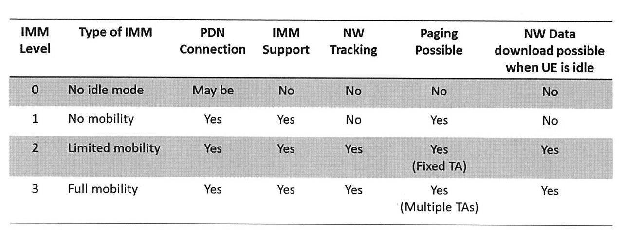
- level 0 to level 3 are defined as mobility levels (IMM) in the idle state of UE 100.
- level 0 does not have an idle state (Idle Mode)
- levels 1 to 3 are targeted as mobility levels in the idle state.
- Level 1 (No mobility) cannot track UE100 from the core network and cannot reach UE100 when UE100 transitions to the idle state.
- the UE 100 can maintain the PDN Connection for a certain period of time in order to enable paging from the core network. This enables data transmission to UE 100 in the idle state.
- Level 2 (Limited mobility) is applied when UE100 stays within a specific TA (Fixed TA). In the case of level 2, UE100 does not need to transmit TAU (TA Update) periodically.
- Level 3 (Full mobility) is applied when UE100 moves across multiple TAs.
- UE 100 transmits TAU (TA Update) to the core network (CP function 30).
- TAU TA Update
- the mobility level selection unit 330 can select an appropriate mobility level at that time according to the moving state of the UE 100 that can change with the passage of time. That is, the mobility level selection unit 330 can dynamically change the mobility level set for the UE 100.
- the mobility level selection unit 330 can select a mobility level based on the presence or absence of movement of the UE 100 acquired by the movement state acquisition unit 320 and the timing of movement. For example, the mobility level selection unit 330 sets the mobility level (any one of levels 1 to 3) corresponding to the movement frequency (for example, one movement / time) of the UE 100 calculated based on the presence / absence and timing of the movement. select.
- the mobility level selection unit 330 can select the mobility level based on the UE 100 moving from a specific TA (predetermined unit area) to another TA (other unit area). Specifically, when the UE 100 moves to a different TA, for example, when the UE 100 moves from the tracking area A1 to the tracking area A2 shown in FIG. ) Is selected.
- the mobility level selection unit 330 can also select a mobility level based on the movement state of the UE 100 and the user information acquired by the information acquisition unit 310.
- the mobility level selection unit 330 can select a mobility level based on the type of UE 100 (eMBB (enhanced mobile broadband), MTC (Machine Type Communication), etc.) in addition to the movement state of UE100.
- the mobility level selection unit 330 basically selects a mobility level (level 1) with a low movement frequency by default, and moves the UE 100 movement frequency or degree of movement.
- Other mobility levels (such as level 2) can be selected only when becomes higher.
- the mobility level notification unit 340 notifies the UE 100 of the mobility level set for the UE 100. Specifically, the mobility level notification unit 340 notifies the UE 100 of the mobility level selected by the mobility level selection unit 330 and inquires whether the UE 100 supports the selected mobility level.
- control channel or a shared data channel can be used for notification to the UE 100 of the selected mobility level.
- the paging processing unit 350 executes processing related to paging for the UE 100. Specifically, the paging processing unit 350 receives a paging request from the CP function 30, and transmits a paging signal to the UE 100 based on the paging request.
- FIGS. 3 and 4 show a communication sequence that accompanies a change in mobility level set in the UE 100. Specifically, FIG. 3 shows a communication sequence for changing the IMM from level 1 to level 3, and FIG. 4 shows a communication sequence for changing the IMM from level 3 to level 1.
- FIG. 5 shows a communication sequence associated with paging for the UE 100.
- UE 100 connected to the temperature sensor is initially installed on an indoor wall surface, and a low mobility level (level 1) is set for UE 100. Then, in order to use UE100 for other purposes, UE100 is installed in a vehicle that moves at high speed, and a high mobility level (level 3) is set for UE100. Furthermore, the vehicle in which the UE 100 is installed stops for a certain time, and a low mobility level (level 1) is set for the UE 100 again.
- Mobility level change (from level 1 to level 3) As shown in FIG. 3, UE100 is installed on an indoor wall surface, and a low mobility level (level 1) is set for UE100 (S10). Further, after the mobility level is set, the UE 100 transmits data (for example, the set IMM level) to the data repository 55.
- data for example, the set IMM level
- the selection of level 1 may be based on the user device for IoT (MTC) in which UE 100 is connected to the temperature sensor, that is, the type of user device, or the movement state of UE 100 is monitored over a predetermined time. It may be based on the result.
- MTC user device for IoT
- UE100 is installed in a vehicle that moves at high speed.
- the UE 100 recovers from the hibernation state at a predetermined timing (Wake up), and detects that it is moving (S15).
- UE 100 notifies ME 300 that it has moved over the tracking area (TA) (Location change across TA) via wireless access network 20 (S20, S30).
- Location change across TA may include the fact that it has moved and the identifiers (cell IDs) of the cells constituting the TA.
- ME300 selects level 3 as the mobility level of UE 100 as the movement state of UE 100 changes.
- the ME 300 notifies the UE 100 of level 3 and inquires whether the selected level is supported (S40).
- the UE 100 returns an acknowledgment (ACK) indicating that the IMM level 3 is supported (S50).
- ACK acknowledgment
- the ME 300 reports to the data repository 55 that the IMM level set for the UE 100 has been changed to level 3 and that the position of the UE 100 has moved (S60).
- the data repository 55 stores the information reported from the ME300. Such information is useful for grasping the movement frequency at which the UE 100 straddles the TA.
- a high mobility level (level 3) is set for the UE 100, and the UE 100 is tracked by the core network (ME300) (S70).
- Mobility level change (from level 3 to level 1) As shown in FIG. 4, the UE 100 is continuously set to a high mobility level (level 3), and the UE 100 transmits data (such as the set IMM level) to the data repository 55 (S110).
- data such as the set IMM level
- the vehicle in which the UE 100 is installed stops for a certain time, and the ME 300 detects that the UE 100 has not moved for a certain time or more (S120).
- the ME 300 can detect that the UE 100 has not moved for a certain time or longer by periodically acquiring information indicating the position of the UE 100.
- the information indicating the position of the UE 100 may be a cell ID, position information indicating more specific longitude and latitude, or GPS (Global Positioning System) information.
- ME300 selects level 1 as the mobility level of UE 100 as the movement state of UE 100 changes.
- ME 300 notifies UE 100 of level 1 and inquires whether the selected level is supported (S130).
- the UE 100 returns an acknowledgment (ACK) indicating that the IMM level 1 is supported (S140).
- ACK acknowledgment
- ME300 reports to the data repository 55 that the IMM level set in UE100 has been changed to level 1 (S150).
- a low mobility level (level 1) is set for the UE 100, and the UE 100 is managed by the core network (ME300) (S160).
- the mobility level of level 2 or level 3 is set for the UE 100, and the UE 100 sets the data (set to the data repository 55). IMM level etc.). (S210).
- the mobility level of the UE 100 is level 1, when the UE 100 is in an idle state, the UE 100 cannot be tracked and cannot reach the UE 100.
- UP function 40 transmits an incoming call notification indicating that data addressed to UE 100 exists to ME 300 (S215).
- ME 300 detects that data addressed to UE 100 (incoming data) has occurred based on the incoming notification (S220). Specifically, the CP function 30 is notified when the incoming data reaches the UP function 40. ME 300 detects that data addressed to UE 100 has occurred based on such an incoming call notification (S220).
- ME 300 transmits a paging signal to UE 100 when data addressed to UE 100 is generated (S230).
- the UE 100 returns an acknowledgment (ACK) for paging (S240).
- ACK acknowledgment
- UE 100 sets a connection (PDN Connection) necessary for data reception based on paging, and executes data reception (and transmission) via UP function 40 (S250).
- PDN Connection a connection necessary for data reception based on paging
- UP function 40 UP function 40
- UE 100 transitions to an idle state when a predetermined time has elapsed after the reception (and transmission) of the data is completed (S260).
- FIG. 6 shows a mobility level selection flow by the ME 300. Specifically, FIG. 6 shows a mobility level selection operation flow in step S40 of FIG. 3 and S130 of FIG. 4 described above.
- the ME 300 acquires information (user information) indicating the type of the UE 100 and information related to movement of the UE 100 (S310). Specifically, the ME 300 acquires the following information.
- UE type eMBB (enhanced mobile broadband), MTC (Machine Type Communication)
- Presence or absence of UE100 movement Lication change
- timing time stamp
- ⁇ subscription based> means based on a contract with a network operator
- ⁇ motion / mobility based> means based on the movement state of UE100.
- ME 300 determines parameters used for selecting the mobility level based on the acquired information (S320). Specifically, ME 300 selects a parameter to be used for selecting a mobility level from among parameters constituting a plurality of pieces of information as described above. The number of parameters to be selected may be single or plural.
- ME 300 selects a mobility level based on the content (value) of the selected parameter (S330). Specifically, ME 300 selects one of the following as the IMM.
- No mobility No IMM
- Level 1 Limited mobility (Limited IMM)
- Level 2 Full mobility (Full IMM) (Level 3)
- ME 300 selects an appropriate mobility level according to the movement state from a plurality of mobility levels (level 1 to level 3) based on the movement state of UE 100.
- ME 300 can appropriately select an appropriate mobility level according to the moving state of UE 100 that can change. Further, by appropriately selecting a mobility level with a low movement frequency, it is possible to achieve both a reduction in the management load of the UE 100 and an improvement in service quality at a higher level.
- the ME 300 can select a mobility level based on the presence / absence of movement of the UE 100 (Location change) and the timing at which the UE 100 moves (time stamp). For this reason, when the movement state of UE100 changes, an appropriate mobility level can be selected quickly and reliably.
- the ME 300 can select the mobility level based on whether or not the UE 100 has moved from the tracking area (TA) where the UE 100 is located to another tracking area. For this reason, even when the UE 100 makes a significant movement across the TA, an appropriate mobility level can be selected quickly and reliably.
- TA tracking area
- the ME 300 can select a mobility level based on user information such as the type of the UE 100 as well as the movement state of the UE 100. For this reason, it can contribute to selection of the more substantial mobility level which considered the characteristic (for example, user apparatus for MTC with a low mobility level).
- each functional block is realized by one device physically and / or logically coupled, and two or more devices physically and / or logically separated may be directly and / or indirectly. (For example, wired and / or wireless) and may be realized by the plurality of devices.
- FIG. 7 is a diagram illustrating an example of a hardware configuration of the ME 300.
- the ME 300 may be configured as a computer device including a processor 1001, a memory 1002, a storage 1003, a communication device 1004, an input device 1005, an output device 1006, a bus 1007, and the like.
- the processor 1001 controls the entire computer by operating an operating system, for example.
- the processor 1001 may be configured by a central processing unit (CPU) including an interface with peripheral devices, a control device, an arithmetic device, a register, and the like.
- CPU central processing unit
- the memory 1002 is a computer-readable recording medium such as a ROM (Read It may be configured by at least one of only memory (EPROM), erasable programmable ROM (EPROM), electrically erasable programmable ROM (EEPROM), random access memory (RAM), and the like.
- the memory 1002 may be called a register, a cache, a main memory (main storage device), or the like.
- the memory 1002 can store programs (program codes), software modules, and the like that can execute the methods according to the above-described embodiments.
- the storage 1003 is a computer-readable recording medium such as an optical disc such as a CD-ROM (Compact Disc ROM), a hard disk drive, a flexible disc, a magneto-optical disc (eg a compact disc, a digital versatile disc, a Blu-ray). (Registered trademark) disk, smart card, flash memory (for example, card, stick, key drive), floppy (registered trademark) disk, magnetic strip, and the like.
- the storage 1003 may be referred to as an auxiliary storage device.
- the above-described storage medium may be, for example, a database, a server, or other suitable medium including the memory 1002 and / or the storage 1003.
- the communication device 1004 is hardware (transmission / reception device) for performing communication between computers via a wired and / or wireless network, and is also referred to as a network device, a network controller, a network card, a communication module, or the like.
- the input device 1005 is an input device (for example, a keyboard, a mouse, a microphone, a switch, a button, a sensor, etc.) that accepts input from the outside.
- the output device 1006 is an output device (for example, a display, a speaker, an LED lamp, or the like) that performs output to the outside. Note that the input device 1005 and the output device 1006 may have an integrated configuration (for example, a touch panel).
- each device such as the processor 1001 and the memory 1002 is connected by a bus 1007 for communicating information.
- the bus 1007 may be configured with a single bus or may be configured with different buses between apparatuses.
- notification of information includes physical layer signaling (eg, DCI (Downlink Control Information), UCI (Uplink Control Information)), upper layer signaling (eg, RRC signaling, MAC (Medium Access Control) signaling, broadcast information (MIB ( Master (Information Block), SIB (System Information Block)), other signals, or combinations thereof, and RRC signaling may also be referred to as RRC messages, eg, RRC Connection Connection message, RRC It may be a Connection ⁇ ⁇ Reconfiguration message.
- RRC messages eg, RRC Connection Connection message, RRC It may be a Connection ⁇ ⁇ Reconfiguration message.
- input / output information may be stored in a specific location (for example, a memory) or may be managed by a management table.
- the input / output information can be overwritten, updated, or appended.
- the output information may be deleted.
- the input information may be transmitted to other devices.
- the specific operation performed by the ME 300 may be performed by another network node (device).
- the function of ME 300 may be provided by a combination of a plurality of other network nodes.
- the function of the paging processing unit 350 may be implemented in another device that constitutes the CP function 30.
- the channel and / or symbol may be a signal.
- the signal may be a message.
- system and “network” may be used interchangeably.
- the parameters described above may be represented by absolute values, may be represented by relative values from predetermined values, or may be represented by other corresponding information.
- the radio resource may be indicated by an index.
- BS 200 can accommodate one or a plurality of (for example, three) cells (also called sectors).
- a base station accommodates multiple cells, the entire coverage area of the base station can be partitioned into multiple smaller areas, each smaller area being a base station subsystem (eg, indoor small base station RRH: Remote Radio Head) can also provide communication services.
- RRH Remote Radio Head
- cell refers to part or all of the coverage area of a base station and / or base station subsystem that provides communication services in this coverage.
- base station eNB
- cell ector
- a base station may also be referred to in terms such as a fixed station (fixed station), NodeB, eNodeB (eNB), access point (access point), femto cell, small cell, and the like.
- UE100 is a subscriber station, mobile unit, subscriber unit, wireless unit, remote unit, mobile device, wireless device, wireless communication device, remote device, mobile subscriber station, access terminal, mobile terminal, wireless terminal by those skilled in the art , Remote terminal, handset, user agent, mobile client, client, or some other appropriate terminology.
- the phrase “based on” does not mean “based only on”, unless expressly specified otherwise. In other words, the phrase “based on” means both “based only on” and “based at least on.”
- an appropriate mobility level can be selected even when the mobility level of the user device in the idle state changes dynamically.
- Wireless communication system 20
- Wireless access network 30
- CP function 40
- UP function 50
- External network 55
- Data repository 100
- UE 200 BS 300
- ME Information acquisition unit
- Movement state acquisition unit 330
- Mobility level selection unit 340
- Mobility level notification unit 350
- Paging processing unit 1001
- Processor 1002
- Memory 1003
- Storage 1004
- Communication device 1005
- Input device 1006
- Output device 1007 Bus A1, A2 Tracking area
Landscapes
- Engineering & Computer Science (AREA)
- Computer Networks & Wireless Communication (AREA)
- Signal Processing (AREA)
- Databases & Information Systems (AREA)
- Physics & Mathematics (AREA)
- Probability & Statistics with Applications (AREA)
- Mobile Radio Communication Systems (AREA)
Abstract
アイドル状態におけるユーザ装置のモビリティレベルが動的に変化する場合でも、適切なモビリティレベルを選択し得るモビリティレベル制御装置及びモビリティレベル制御方法を提供する。ME(300)は、ユーザ装置の移動状態に応じて、アイドル状態におけるユーザ装置のモビリティレベル(IMM)を制御する。ME(300)は、ユーザ装置の移動状態を取得する移動状態取得部(320)と、移動状態取得部(320)が取得したユーザ装置の移動状態に基づいて、複数のモビリティレベルの中から何れかのモビリティレベルを選択するモビリティレベル選択部(330)と、モビリティレベル選択部(330)によって選択されたモビリティレベルをユーザ装置に通知するモビリティレベル通知部(340)とを備える。
Description
本発明は、アイドル状態におけるユーザ装置のモビリティレベルを制御するモビリティレベル制御装置及びモビリティレベル制御方法に関する。
3rd Generation Partnership Project(3GPP)は、Long Term Evolution(LTE)の更なる高速化を目的としてLTE-Advanced(以下、LTE-Advancedを含めてLTEという)を仕様化している。また、3GPPでは、さらに、5G(5th generation mobile communication system)などと呼ばれるLTEの後継システムの仕様が検討されている。
このような後継システムでは、Internet of Things(IoT)向けのユーザ装置、及び非IoT向けのユーザ装置など、これまで以上に多くの種類のユーザ装置が用いられることが想定されている。そこで、アイドル状態におけるユーザ装置のモビリティレベルを複数定義することが検討されている(例えば、非特許文献1)。これにより、ユーザ装置の管理負荷の軽減と、サービス品質の向上とを両立し得る。
具体的には、ユーザ装置の種別や特徴に応じて、移動頻度(または移動の程度、以下同)が低いモビリティレベルから、移動頻度が高いモビリティレベルまでの複数のモビリティレベルの中から、当該ユーザ装置を何れかのモビリティレベルに設定することが検討されている。
Solution: Mobility Options, SA WG2 Meeting #114, S2-161625、3GPP、2016年4月
しかしながら、上述したユーザ装置に対するモビリティレベルの設定には、次のような問題がある。すなわち、各ユーザ装置に対して、何れかのモビリティレベルが固定的に設定されるため、ユーザ装置の移動状態、つまり、モビリティレベルが変化した場合には、既に当該ユーザ装置に対して設定されているモビリティレベルと合致しない場合が発生し得る。
例えば、温度センサと接続されたユーザ装置が屋内に設置される場合、一般的には移動頻度が低いモビリティレベルが設定される。その後、当該ユーザ装置を他の用途で使用するため、車両内などに設置した場合、当該ユーザ装置は、頻繁に移動する可能性がある。従って、移動頻度が低いモビリティレベルでは、当該ユーザ装置に対して要求されるサービス品質を確保できない恐れがある。
そこで、本発明は、このような状況に鑑みてなされたものであり、アイドル状態におけるユーザ装置のモビリティレベルが動的に変化する場合でも、適切なモビリティレベルを選択し得るモビリティレベル制御装置及びモビリティレベル制御方法の提供を目的とする。
本発明の一態様は、ユーザ装置(UE100)の移動状態に応じて、アイドル状態における前記ユーザ装置のモビリティレベル(IMM)を制御するモビリティレベル制御装置(ME300)であって、前記ユーザ装置の移動状態を取得する移動状態取得部(移動状態取得部320)と、前記移動状態取得部が取得した前記ユーザ装置の移動状態に基づいて、複数の前記モビリティレベルの中から何れかの前記モビリティレベルを選択するモビリティレベル選択部(モビリティレベル選択部330)と、前記モビリティレベル選択部によって選択された前記モビリティレベルを前記ユーザ装置に通知するモビリティレベル通知部(モビリティレベル通知部340)とを備える。
本発明の一態様は、ユーザ装置の移動状態に応じて、アイドル状態における前記ユーザ装置のモビリティレベルを制御する制御装置におけるモビリティレベル制御方法であって、前記制御装置が、前記ユーザ装置の移動状態に基づいて、複数の前記モビリティレベルの中から何れかの前記モビリティレベルを選択するステップと、前記制御装置が、選択した前記モビリティレベルを前記ユーザ装置に通知するステップとを含む。
以下、実施形態を図面に基づいて説明する。なお、同一の機能や構成には、同一または類似の符号を付して、その説明を適宜省略する。
(1)無線通信システムの全体概略構成
図1は、本実施形態に係る無線通信システム10の全体概略構成図である。無線通信システム10は、Long Term Evolution(LTE)の後継システムである「5G」に従った無線通信システムである。なお、無線通信システム10は、FRA(Future Radio Access)或いは次世代システム(NextGen)などと呼ばれてもよい。
図1は、本実施形態に係る無線通信システム10の全体概略構成図である。無線通信システム10は、Long Term Evolution(LTE)の後継システムである「5G」に従った無線通信システムである。なお、無線通信システム10は、FRA(Future Radio Access)或いは次世代システム(NextGen)などと呼ばれてもよい。
図1に示すように、無線通信システム10は、無線アクセスネットワーク20、コアネットワーク制御プレーン機能30(以下、CP機能30)、コアネットワークユーザプレーン機能40(以下、UP機能40)及びユーザ装置100(以下、UE100)を含む。また、無線通信システム10、具体的には、UP機能40には、外部ネットワーク50が接続される。
無線アクセスネットワーク20は、例えば、3rd Generation Partnership Project(3GPP)において規定される無線アクセス技術(RAT)に従った無線ネットワークであり、無線基地局200(以下、BS200)を含む。
無線アクセスネットワーク20には、CP機能30及びUP機能40が接続される。CP機能30及びUP機能40は、無線通信システム10のコアネットワークにおける制御プレーン機能及びユーザプレーン機能を提供する。つまり、無線通信システム10のコアネットワークでは、UE100及びBS200などの制御を実現する制御プレーンの機能と、ユーザデータの送受信などを実現するユーザプレーンの機能とが明確に分離された形態(CUPS: C/U plane separation)が採用されている。CP機能30及びUP機能40は、それぞれ、Serving Gateway(SGW)、PDN Gateway(PGW)及びTraffic Detection Function(TDF)などによって構成される。
外部ネットワーク50は、UP機能40に接続される。代表的な外部ネットワーク50の例は、インターネットであるが、外部ネットワーク50の種類は、特に限定されず、無線通信システム10のオペレータなどによって提供されるプライベートのネットワークでも構わない。
また、外部ネットワーク50には、データレポジトリ55が設けられる。データレポジトリ55は、UE100から送信されたデータ(後述するIMMのレベルなど)を保管する。
UE100及びBS200は、3GPPにおいて規定される無線通信技術に従った無線通信を実行する。本実施形態では、UE100の種別は、特に限定されない。UE100は、Internet of Things(IoT)向け、例えば、MTC(Machine Type Communication)向けのユーザ装置であってもよいし、従来のスマートフォンのような非IoT向けのユーザ装置であってもよい。
UE100は、上述したような種別及び用途などに応じて、移動頻度または移動の程度が変化し得る。移動頻度とは、所定時間内にUE100が移動する回数であり、移動する距離とは関係がない。一方、移動の程度とは、典型的には、所定時間内に移動した距離である。但し、必ずしも距離でなく、後述するトラッキングエリア(TA)など、地理的な移動の程度を判定することが可能な単位を用いてもよい。以下、このようなUE100の移動頻度または移動の程度の少なくとも何れかを「移動状態」という。
UE100の移動状態は、上述したような種別及び用途などに応じて、全く移動しない状態から、高速で移動する状態まで変化する可能性がある。本実施形態では、UE100の移動状態に応じた複数のモビリティレベルが定義されており、動的に変化するUE100の移動状態に応じて、複数のモビリティレベルから、何れかのモビリティレベルが選択される。
移動制御エンティティ300(以下、ME300)は、CP機能30を構成する装置の一つである。本実施形態では、ME300は、モビリティレベル制御装置を構成する。
ME300は、UE100の移動状態に応じて、アイドル状態におけるUE100のモビリティレベルを制御する。
アイドル状態とは、UE100がCP機能30及びUP機能40によって構成されるコアネットワークと接続されているが、アクティブなユーザプレーンの経路(ユーザデータパス、ユーザデータ用ベアラまたはコネクションなどと呼ばれてもよい)などとを有していない状態をいう。アイドル状態のUE100は、上述したような種別及び用途などに応じて移動状態が変化し得る。
ME300は、UE100のアイドル状態におけるモビリティレベルを制御することによって、UE100のモビリティレベルを適宜更新することができる。例えば、ME300は、UE100がパケットデータ用のコネクション(PDN Connection)を確立する際におけるUE100のモビリティレベルを制御することができる。なお、以下、UE100のアイドル状態におけるモビリティレベルを、適宜Idle Mode Mobility(IMM)という。
ME300は、UE100の移動状態と対応する最適なモビリティレベルを動的に選択する。また、ME300は、UE100の移動状態を定期的に取得し、UE100の最新の移動状態に基づいて、UE100のモビリティレベルを更新することができる。このようなME300の提供機能を考慮し、ME300は、On Demand Management Entityなどと呼ばれてもよい。
(2)無線通信システムの機能ブロック構成
次に、無線通信システム10の機能ブロック構成について説明する。具体的には、ME300の機能ブロック構成について説明する。
次に、無線通信システム10の機能ブロック構成について説明する。具体的には、ME300の機能ブロック構成について説明する。
図2は、ME300の機能ブロック構成図である。図2に示すように、ME300は、情報取得部310、移動状態取得部320、モビリティレベル選択部330、モビリティレベル通知部340及びページング処理部350を備える。
情報取得部310は、無線アクセスネットワーク20に接続されている、具体的には、アタッチされているUE100に関する情報(ユーザ情報)を取得する。
ユーザ情報とは、UE100の属性または状態の少なくとも何れかを示すものである。属性とは、UE100の特徴または性質を示すものであり、UE100が予め備えるもの、或いはUE100に対して予め要求されるものである。例えば、UE100の種別、要求されるサービス品質(QoS)及び遅延時間(Latency)などが挙げられる。
状態とは、UE100の様子または境遇などを示すものであり、UE100の使用態様などによって変化し得る。例えば、UE100が送受信するデータのトラフィックパターンなどが挙げられる。また、UE100が接続(アタッチ)する無線アクセスネットワーク20、及びUP機能40によって提供されるコアネットワークの種別は、UE100の状態に含まれる。
移動状態取得部320は、UE100の移動状態を取得する。移動状態とは、上述したように、UE100の移動頻度または移動の程度である。
具体的には、移動状態取得部320は、UE100の移動(Location change)の有無、及びUE100が移動したタイミングを取得することができる。より具体的には、移動状態取得部320は、UE100から報告されるLocation change、及び当該Location changeが発生した時刻情報を取得する。なお、Location changeが発生したタイミングは、必ずしも時刻情報でなくてもよく、所定の時点を基準とした経過時間などによって示されてもよい。
また、移動状態取得部320は、UE100が所定の単位エリアから他の単位エリアに移動したか否かを取得することもできる。具体的には、移動状態取得部320は、UE100が位置するトラッキングエリア(TA)から他のトラッキングエリアに移動したか否かを取得する。
なお、トラッキングエリアとは、1つまたは複数のセルから構成され、コアネットワーク上で管理されるUE100の位置を示す単位エリアである。
モビリティレベル選択部330は、UE100に対応付けられるモビリティレベルとして、数のモビリティレベルの中から何れかのモビリティレベルを選択する。具体的には、モビリティレベル選択部330は、移動状態取得部320が取得したUE100の移動状態に基づいて、複数のモビリティレベルの中から何れかのモビリティレベルを選択する。
本実施形態では、表1に示すように、UE100のアイドル状態におけるモビリティレベル(IMM)として、レベル0~レベル3の4つのレベルが定義される。
なお、レベル0は、アイドル状態(Idle Mode)が存在しないため、アイドル状態におけるモビリティレベルとしては、レベル1~レベル3が対象である。レベル1(No mobility)は、UE100がアイドル状態に遷移すると、コアネットワークからはUE100をトラッキングすることができず、UE100に到達できない。但し、UE100は、コアネットワークからのページングを可能とするため、PDN Connectionを一定時間に亘って維持することができる。これにより、アイドル状態のUE100に対するデータ送信を可能とする。
レベル2(Limited mobility)は、UE100が特定のTA(Fixed TA)内での移動に留まる場合に適用される。レベル2の場合、UE100は、TAU(TA Update)を定期的に送信する必要がない。
レベル3(Full mobility)は、UE100が複数のTAを跨がって移動する場合に適用される。レベル3の場合、UE100は、TAU(TA Update)をコアネットワーク(CP機能30)に対して送信する。
モビリティレベル選択部330は、このように、時間の経過に応じて変化し得るUE100の移動状態に応じて、その時点における適切なモビリティレベルを選択することができる。つまり、モビリティレベル選択部330は、UE100に対して設定されるモビリティレベルを動的に変更することができる。
モビリティレベル選択部330は、移動状態取得部320によって取得されたUE100の移動の有無と、移動のタイミングとに基づいて、モビリティレベルを選択することができる。例えば、モビリティレベル選択部330は、当該移動の有無とタイミングとに基づいて算出されるUE100の移動頻度(例えば、移動1回/時間)と対応するモビリティレベル(レベル1~3の何れか)を選択する。
また、モビリティレベル選択部330は、UE100が特定のTA(所定の単位エリア)から他のTA(他の単位エリア)に移動したことに基づいて、モビリティレベルを選択することができる。具体的には、モビリティレベル選択部330は、UE100が異なるTAに移動した場合、例えば、図1に示すトラッキングエリアA1からトラッキングエリアA2に移動した場合、UE100のモビリティレベルとして、レベル3(Full mobility)を選択する。
さらに、モビリティレベル選択部330は、UE100の移動状態及び情報取得部310によって取得されたユーザ情報に基づいて、モビリティレベルを選択することもできる。例えば、モビリティレベル選択部330は、UE100の移動状態に加え、UE100の種別(eMBB(enhanced mobile broadband), MTC(Machine Type Communication)など)に基づいて、モビリティレベルを選択することができる。具体的には、モビリティレベル選択部330は、UE100の種別がMTCであれば、基本的には、移動頻度が低いモビリティレベル(レベル1)をデフォルトで選択し、UE100の移動頻度または移動の程度が高くなった場合のみ、他のモビリティレベル(レベル2など)を選択することができる。
モビリティレベル通知部340は、UE100に設定されるモビリティレベルをUE100に通知する。具体的には、モビリティレベル通知部340は、モビリティレベル選択部330によって選択されたモビリティレベルをUE100に通知するとともに、選択されたモビリティレベルをUE100がサポートしているか否かを問い合わせる。
なお、選択されたモビリティレベルのUE100への通知には、制御チャネルまたは共有データチャネルを用いることができる。
ページング処理部350は、UE100に対するページングに関する処理を実行する。具体的には、ページング処理部350は、CP機能30からのページング要求を受信し、当該ページング要求に基づいて、UE100にページング信号を送信する。
(3)無線通信システムの動作
次に、無線通信システム10の動作について説明する。具体的には、UE100に設定されるモビリティレベルを動的に変更する動作、及びアイドル状態のUE100に対するページング動作について説明する。
次に、無線通信システム10の動作について説明する。具体的には、UE100に設定されるモビリティレベルを動的に変更する動作、及びアイドル状態のUE100に対するページング動作について説明する。
(3.1)通信シーケンス
図3及び図4は、UE100に設定されるモビリティレベルの変更に伴う通信シーケンスを示す。具体的には、図3は、IMMをレベル1からレベル3に変更する通信シーケンスを示し、図4は、IMMをレベル3からレベル1に変更する通信シーケンスを示す。
図3及び図4は、UE100に設定されるモビリティレベルの変更に伴う通信シーケンスを示す。具体的には、図3は、IMMをレベル1からレベル3に変更する通信シーケンスを示し、図4は、IMMをレベル3からレベル1に変更する通信シーケンスを示す。
また、図5は、UE100に対するページングに伴う通信シーケンスを示す。
本実施形態では、以下のようなユースケースを想定する。すなわち、温度センサと接続されたUE100が当初、屋内の壁面に設置され、UE100に対して低いモビリティレベル(レベル1)が設定される。その後、UE100を他の用途で使用するため、UE100が高速で移動する車両内に設置され、UE100に対して高いモビリティレベル(レベル3)が設定される。さらに、UE100が設置された車両が一定時間に亘って停止し、UE100に対して再び低いモビリティレベル(レベル1)が設定される。
(3.1.1)モビリティレベルの変更(レベル1からレベル3)
図3に示すように、UE100は、屋内の壁面に設置され、UE100に対して低いモビリティレベル(レベル1)が設定される(S10)。また、UE100は、モビリティレベルが設定された後、データレポジトリ55に対してデータ(例えば、設定されたIMMのレベルなど)を送信する。
図3に示すように、UE100は、屋内の壁面に設置され、UE100に対して低いモビリティレベル(レベル1)が設定される(S10)。また、UE100は、モビリティレベルが設定された後、データレポジトリ55に対してデータ(例えば、設定されたIMMのレベルなど)を送信する。
なお、レベル1の選択は、UE100が温度センサと接続されたIoT(MTC)向けのユーザ装置、つまり、ユーザ装置の種別に基づいてもよいし、所定時間に亘ってUE100の移動状態を監視した結果に基づいてもよい。
その後、UE100は、高速で移動する車両内に設置される。UE100は、所定タイミングで休止状態から復旧(Wake up)し、移動していることを検出する(S15)。
UE100は、トラッキングエリア(TA)を跨ぐような移動をしたこと(Location change across TA)を、無線アクセスネットワーク20を介してME300に通知する(S20, S30)。Location change across TAには、移動したこと、及びTAを構成するセルの識別子(セルID)が含まれてもよい。
ME300は、UE100の移動状態が変化したことに伴い、UE100のモビリティレベルとして、レベル3を選択する。ME300は、レベル3をUE100に対して通知し、選択されたレベルをサポートしているか否かを問い合わせる(S40)。UE100は、IMMのレベル3をサポートしていることを示す肯定応答(ACK)を返送する(S50)。
ME300は、UE100に設定されるIMMのレベルがレベル3に変更になったこと、及びUE100の位置が移動したことをデータレポジトリ55に報告する(S60)。
データレポジトリ55は、ME300から報告された当該情報を保存する。このような情報は、UE100がTAを跨ぐような移動頻度を把握するために有用である。
この結果、UE100には高いモビリティレベル(レベル3)が設定され、UE100は、コアネットワーク(ME300)によってトラッキングされる(S70)。
(3.1.2)モビリティレベルの変更(レベル3からレベル1)
図4に示すように、UE100には引き続き高いモビリティレベル(レベル3)が設定され、UE100は、データレポジトリ55に対してデータ(設定されたIMMのレベルなど)を送信する(S110)。
図4に示すように、UE100には引き続き高いモビリティレベル(レベル3)が設定され、UE100は、データレポジトリ55に対してデータ(設定されたIMMのレベルなど)を送信する(S110)。
その後、UE100が設置された車両が一定時間に亘って停止し、ME300は、UE100が一定時間以上、移動していないことを検出する(S120)。なお、ME300は、UE100の位置を示す情報を定期的に取得することによって、UE100が一定時間以上、移動していないことを検出することができる。なお、UE100の位置を示す情報は、セルIDでもよいし、より具体的な経度及び緯度を示すような位置情報、或いはGPS(Global Positioning system)の情報でも構わない。
ME300は、UE100の移動状態が変化したことに伴い、UE100のモビリティレベルとして、レベル1を選択する。ME300は、レベル1をUE100に対して通知し、選択されたレベルをサポートしているか否かを問い合わせる(S130)。UE100は、IMMのレベル1をサポートしていることを示す肯定応答(ACK)を返送する(S140)。
ME300は、UE100に設定されるIMMのレベルがレベル1に変更になったことをデータレポジトリ55に報告する(S150)。
この結果、UE100には低いモビリティレベル(レベル1)が設定され、UE100は、コアネットワーク(ME300)によって管理される(S160)。
(3.1.3)ページング
図5に示すように、ここでは、UE100に対してレベル2またはレベル3のモビリティレベルが設定されており、UE100は、データレポジトリ55に対してデータ(設定されたIMMのレベルなど)を送信する。(S210)。なお、上述したように、UE100のモビリティレベルがレベル1の場合には、UE100がアイドル状態の場合、UE100をトラッキングすることができず、UE100に到達できない。
図5に示すように、ここでは、UE100に対してレベル2またはレベル3のモビリティレベルが設定されており、UE100は、データレポジトリ55に対してデータ(設定されたIMMのレベルなど)を送信する。(S210)。なお、上述したように、UE100のモビリティレベルがレベル1の場合には、UE100がアイドル状態の場合、UE100をトラッキングすることができず、UE100に到達できない。
次いで、UE100宛てのデータが発生し、UP機能40は、UE100宛てのデータを存在することを示す着信通知をME300に送信する(S215)。
ME300は、当該着信通知に基づいて、UE100宛てのデータ(着信データ)が発生したことを検出する(S220)。具体的には、当該着信データがUP機能40に到達したことを契機として、CP機能30に通知される。ME300は、このような着信通知に基づいてUE100宛てのデータが発生したことを検出する(S220)。
ME300は、UE100宛てのデータが発生したことに伴い、UE100に対するページング信号を送信する(S230)。UE100は、ページングに対する肯定応答(ACK)を返送する(S240)。
UE100は、ページングに基づいて、データ受信に必要なコネクション(PDN Connection)を設定し、UP機能40を経由したデータの受信(及び送信)を実行する(S250)。
UE100は、当該データの受信(及び送信)が完了して一定時間経過すると、アイドル状態に遷移する(S260)。
(3.2)モビリティレベル選択フロー
図6は、ME300によるモビリティレベルの選択フローを示す。具体的には、図6は、上述した図3のステップS40及び図4のS130におけるモビリティレベルの選択動作フローを示す。
図6は、ME300によるモビリティレベルの選択フローを示す。具体的には、図6は、上述した図3のステップS40及び図4のS130におけるモビリティレベルの選択動作フローを示す。
図6に示すように、ME300は、UE100の種別を示す情報(ユーザ情報)及びUE100の移動に関する情報を取得する(S310)。具体的には、ME300は、次のような情報を取得する。
1) UE種別(eMBB(enhanced mobile broadband), MTC(Machine Type Communication))
2) UE100の移動(Location change)の有無、及びタイミング(time stamp)
なお、<subscription based>とは、ネットワークオペレータとの契約に基づくことを意味し、<motion/mobility based>とは、UE100の移動状態に基づくことを意味する。
2) UE100の移動(Location change)の有無、及びタイミング(time stamp)
なお、<subscription based>とは、ネットワークオペレータとの契約に基づくことを意味し、<motion/mobility based>とは、UE100の移動状態に基づくことを意味する。
ME300は、取得した当該情報に基づいて、モビリティレベルの選択に用いるパラメータを決定する(S320)。具体的には、ME300は、上述したような複数の情報を構成するパラメータの中から、モビリティレベルの選択に用いるパラメータを選択する。なお、選択するパラメータの数は、単一でもよいし、複数でもよい。
ME300は、選択した当該パラメータの内容(値)に基づいて、モビリティレベルを選択する(S330)。具体的には、ME300は、IMMとして次の何れかを選択する。
・ No mobility(No IMM)(レベル1)
・ Limited mobility(Limited IMM)(レベル2)
・ Full mobility(Full IMM)(レベル3)
・ Limited mobility(Limited IMM)(レベル2)
・ Full mobility(Full IMM)(レベル3)
(4)作用・効果
上述した実施形態によれば、以下の作用効果が得られる。具体的には、ME300は、UE100の移動状態に基づいて、複数のモビリティレベル(レベル1~レベル3)の中から、当該移動状態に応じた適切なモビリティレベルを選択する。
上述した実施形態によれば、以下の作用効果が得られる。具体的には、ME300は、UE100の移動状態に基づいて、複数のモビリティレベル(レベル1~レベル3)の中から、当該移動状態に応じた適切なモビリティレベルを選択する。
このため、アイドル状態におけるUE100のモビリティレベルが動的に変化する場合でも、適切なモビリティレベルを動的に選択し得る。より具体的には、ME300は、変化し得るUE100の移動状態に応じて、適切なモビリティレベルを適宜選択することができる。また、移動頻度が低いモビリティレベルが適切に選択されることによって、UE100の管理負荷の軽減と、サービス品質の向上とを、より高い次元で両立し得る。
なお、先行技術文献に記載された複数のモビリティレベルの提案では、UE100に対して何れかのモビリティレベルが固定的に設定されるため、UE100の移動状態が動的に変化した場合には、対応できない。
また、本実施形態では、ME300は、UE100の移動(Location change)の有無、及びUE100が移動したタイミング(time stamp)に基づいてモビリティレベルを選択することができる。このため、UE100の移動状態が変化した場合に、迅速かつ確実に適切なモビリティレベルを選択することができる。
さらに、本実施形態では、ME300は、UE100が位置するトラッキングエリア(TA)から他のトラッキングエリアに移動したか否かに基づいてモビリティレベルを選択することができる。このため、UE100がTAを跨ぐような大幅な移動をした場合でも、迅速かつ確実に適切なモビリティレベルを選択することができる。
本実施形態では、ME300は、UE100の移動状態のみでなく、UE100の種別などのユーザ情報に基づいて、モビリティレベルを選択することができる。このため、UE100の特徴(例えば、モビリティレベルが低いMTC向けのユーザ装置)を加味した、より実質的なモビリティレベルの選択に寄与し得る。
(5)その他の実施形態
以上、実施形態に沿って本発明の内容を説明したが、本発明はこれらの記載に限定されるものではなく、種々の変形及び改良が可能であることは、当業者には自明である。
以上、実施形態に沿って本発明の内容を説明したが、本発明はこれらの記載に限定されるものではなく、種々の変形及び改良が可能であることは、当業者には自明である。
例えば、上述した実施形態の説明に用いたブロック図は、機能ブロック図を示している。これらの機能ブロック(構成部)は、ハードウェア及び/またはソフトウェアの任意の組み合わせによって実現される。また、各機能ブロックの実現手段は特に限定されない。すなわち、各機能ブロックは、物理的及び/または論理的に結合した1つの装置により実現されてもよいし、物理的及び/または論理的に分離した2つ以上の装置を直接的及び/または間接的に(例えば、有線及び/または無線)で接続し、これら複数の装置により実現されてもよい。
また、上述したME300は、本発明の無線通信方法の処理を行うコンピュータとして機能してもよい。図7は、ME300のハードウェア構成の一例を示す図である。図7に示すように、ME300は、プロセッサ1001、メモリ1002、ストレージ1003、通信装置1004、入力装置1005、出力装置1006及びバス1007などを含むコンピュータ装置として構成されてもよい。
プロセッサ1001は、例えば、オペレーティングシステムを動作させてコンピュータ全体を制御する。プロセッサ1001は、周辺装置とのインターフェース、制御装置、演算装置、レジスタなどを含む中央処理装置(CPU)で構成されてもよい。
メモリ1002は、コンピュータ読み取り可能な記録媒体であり、例えば、ROM(Read
Only Memory)、EPROM(Erasable Programmable ROM)、EEPROM(Electrically Erasable Programmable ROM)、RAM(Random Access Memory)などの少なくとも1つで構成されてもよい。メモリ1002は、レジスタ、キャッシュ、メインメモリ(主記憶装置)などと呼ばれてもよい。メモリ1002は、上述した実施形態に係る方法を実行可能なプログラム(プログラムコード)、ソフトウェアモジュールなどを保存することができる。
Only Memory)、EPROM(Erasable Programmable ROM)、EEPROM(Electrically Erasable Programmable ROM)、RAM(Random Access Memory)などの少なくとも1つで構成されてもよい。メモリ1002は、レジスタ、キャッシュ、メインメモリ(主記憶装置)などと呼ばれてもよい。メモリ1002は、上述した実施形態に係る方法を実行可能なプログラム(プログラムコード)、ソフトウェアモジュールなどを保存することができる。
ストレージ1003は、コンピュータ読み取り可能な記録媒体であり、例えば、CD-ROM(Compact Disc ROM)などの光ディスク、ハードディスクドライブ、フレキシブルディスク、光磁気ディスク(例えば、コンパクトディスク、デジタル多用途ディスク、Blu-ray(登録商標)ディスク)、スマートカード、フラッシュメモリ(例えば、カード、スティック、キードライブ)、フロッピー(登録商標)ディスク、磁気ストリップなどの少なくとも1つで構成されてもよい。ストレージ1003は、補助記憶装置と呼ばれてもよい。上述の記憶媒体は、例えば、メモリ1002及び/またはストレージ1003を含むデータベース、サーバその他の適切な媒体であってもよい。
通信装置1004は、有線及び/または無線ネットワークを介してコンピュータ間の通信を行うためのハードウェア(送受信デバイス)であり、例えばネットワークデバイス、ネットワークコントローラ、ネットワークカード、通信モジュールなどともいう。
入力装置1005は、外部からの入力を受け付ける入力デバイス(例えば、キーボード、マウス、マイクロフォン、スイッチ、ボタン、センサなど)である。出力装置1006は、外部への出力を実施する出力デバイス(例えば、ディスプレイ、スピーカー、LEDランプなど)である。なお、入力装置1005及び出力装置1006は、一体となった構成(例えば、タッチパネル)であってもよい。
また、プロセッサ1001及びメモリ1002などの各装置は、情報を通信するためのバス1007で接続される。バス1007は、単一のバスで構成されてもよいし、装置間で異なるバスで構成されてもよい。
また、情報の通知は、上述した実施形態に限られず、他の方法で行われてもよい。例えば、情報の通知は、物理レイヤシグナリング(例えば、DCI(Downlink Control Information)、UCI(Uplink Control Information))、上位レイヤシグナリング(例えば、RRCシグナリング、MAC(Medium Access Control)シグナリング、報知情報(MIB(Master Information Block)、SIB(System Information Block))、その他の信号またはこれらの組み合わせによって実施されてもよい。また、RRCシグナリングは、RRCメッセージと呼ばれてもよく、例えば、RRC Connection Setupメッセージ、RRC Connection Reconfigurationメッセージなどであってもよい。
さらに、入出力された情報は、特定の場所(例えば、メモリ)に保存されてもよいし、管理テーブルで管理してもよい。入出力される情報は、上書き、更新、または追記され得る。出力された情報は削除されてもよい。入力された情報は他の装置へ送信されてもよい。
上述した実施形態におけるシーケンス及びフローチャートなどは、矛盾の無い限り、順序を入れ替えてもよい。
また、上述した実施形態において、ME300によって行われるとした特定動作は、他のネットワークノード(装置)によって行われることもある。また、複数の他のネットワークノードの組み合わせによってME300の機能が提供されても構わない。さらに、ページング処理部350の機能は、CP機能30を構成する他の装置に実装されてもよい。
なお、本明細書で説明した用語及び/または本明細書の理解に必要な用語については、同一のまたは類似する意味を有する用語と置き換えてもよい。例えば、チャネル及び/またはシンボルは信号(シグナル)であってもよい。また、信号はメッセージであってもよい。また、「システム」及び「ネットワーク」という用語は、互換的に使用されてもよい。
さらに、上述したパラメータなどは、絶対値で表されてもよいし、所定の値からの相対値で表されてもよいし、対応する別の情報で表されてもよい。例えば、無線リソースはインデックスで指示されるものであってもよい。
BS200(基地局)は、1つまたは複数(例えば、3つ)のセル(セクタとも呼ばれる)を収容することができる。基地局が複数のセルを収容する場合、基地局のカバレッジエリア全体は複数のより小さいエリアに区分でき、各々のより小さいエリアは、基地局サブシステム(例えば、屋内用の小型基地局RRH:Remote Radio Head)によって通信サービスを提供することもできる。
「セル」または「セクタ」という用語は、このカバレッジにおいて通信サービスを行う基地局、及び/または基地局サブシステムのカバレッジエリアの一部または全体を指す。さらに、「基地局」「eNB」、「セル」、及び「セクタ」という用語は、本明細書では互換的に使用され得る。基地局は、固定局(fixed station)、NodeB、eNodeB(eNB)、アクセスポイント(access point)、フェムトセル、スモールセルなどの用語で呼ばれる場合もある。
UE100は、当業者によって、加入者局、モバイルユニット、加入者ユニット、ワイヤレスユニット、リモートユニット、モバイルデバイス、ワイヤレスデバイス、ワイヤレス通信デバイス、リモートデバイス、モバイル加入者局、アクセス端末、モバイル端末、ワイヤレス端末、リモート端末、ハンドセット、ユーザエージェント、モバイルクライアント、クライアント、またはいくつかの他の適切な用語で呼ばれる場合もある。
本明細書で使用する「に基づいて」という記載は、別段に明記されていない限り、「のみに基づいて」を意味しない。言い換えれば、「に基づいて」という記載は、「のみに基づいて」と「に少なくとも基づいて」の両方を意味する。
また、「含む(including)」、「含んでいる(comprising)」、及びそれらの変形の用語は、「備える」と同様に、包括的であることが意図される。さらに、本明細書或いは特許請求の範囲において使用されている用語「または(or)」は、排他的論理和ではないことが意図される。
上記のように、本発明の実施形態を記載したが、この開示の一部をなす論述及び図面はこの発明を限定するものであると理解すべきではない。この開示から当業者には様々な代替実施の形態、実施例及び運用技術が明らかとなろう。
なお、日本国特許出願第2016-097251号(2016年5月13日出願)の全内容が、参照により、本願明細書に組み込まれている。
上述したモビリティレベル制御装置及びモビリティレベル制御方法によれば、アイドル状態におけるユーザ装置のモビリティレベルが動的に変化する場合でも、適切なモビリティレベルを選択し得る。
10 無線通信システム
20 無線アクセスネットワーク
30 CP機能
40 UP機能
50 外部ネットワーク
55 データレポジトリ
100 UE
200 BS
300 ME
310 情報取得部
320 移動状態取得部
330 モビリティレベル選択部
340 モビリティレベル通知部
350 ページング処理部
1001 プロセッサ
1002 メモリ
1003 ストレージ
1004 通信装置
1005 入力装置
1006 出力装置
1007 バス
A1, A2 トラッキングエリア
20 無線アクセスネットワーク
30 CP機能
40 UP機能
50 外部ネットワーク
55 データレポジトリ
100 UE
200 BS
300 ME
310 情報取得部
320 移動状態取得部
330 モビリティレベル選択部
340 モビリティレベル通知部
350 ページング処理部
1001 プロセッサ
1002 メモリ
1003 ストレージ
1004 通信装置
1005 入力装置
1006 出力装置
1007 バス
A1, A2 トラッキングエリア
Claims (5)
- ユーザ装置の移動状態に応じて、アイドル状態における前記ユーザ装置のモビリティレベルを制御するモビリティレベル制御装置であって、
前記ユーザ装置の移動状態を取得する移動状態取得部と、
前記移動状態取得部が取得した前記ユーザ装置の移動状態に基づいて、複数の前記モビリティレベルの中から何れかの前記モビリティレベルを選択するモビリティレベル選択部と、
前記モビリティレベル選択部によって選択された前記モビリティレベルを前記ユーザ装置に通知するモビリティレベル通知部と
を備えるモビリティレベル制御装置。 - 前記移動状態取得部は、前記ユーザ装置の移動の有無、及び前記ユーザ装置が移動したタイミングを取得し、
前記モビリティレベル選択部は、前記移動の有無と前記タイミングとに基づいて、前記モビリティレベルを選択する請求項1に記載のモビリティレベル制御装置。 - 前記移動状態取得部は、前記ユーザ装置が所定の単位エリアから他の単位エリアに移動したか否かを取得し、
前記モビリティレベル選択部は、前記ユーザ装置が前記所定の単位エリアから他の単位エリアに移動したことに基づいて、前記モビリティレベルを選択する請求項1に記載のモビリティレベル制御装置。 - 前記ユーザ装置の属性または状態の少なくとも何れかを示すユーザ情報を取得す情報取得部を備え、
前記モビリティレベル選択部は、前記ユーザ装置の移動状態及び前記情報取得部によって取得された前記ユーザ情報に基づいて、前記モビリティレベルを選択する請求項1に記載のモビリティレベル制御装置。 - ユーザ装置の移動状態に応じて、アイドル状態における前記ユーザ装置のモビリティレベルを制御する制御装置におけるモビリティレベル制御方法であって、
前記制御装置が、前記ユーザ装置の移動状態に基づいて、複数の前記モビリティレベルの中から何れかの前記モビリティレベルを選択するステップと、
前記制御装置が、選択した前記モビリティレベルを前記ユーザ装置に通知するステップと
を含むモビリティレベル制御方法。
Priority Applications (3)
| Application Number | Priority Date | Filing Date | Title |
|---|---|---|---|
| JP2018517074A JP7122253B2 (ja) | 2016-05-13 | 2017-05-11 | モビリティレベル制御装置及びモビリティレベル制御方法 |
| CN201780029658.7A CN109155981A (zh) | 2016-05-13 | 2017-05-11 | 移动性等级控制装置以及移动性等级控制方法 |
| US16/300,106 US11723117B2 (en) | 2016-05-13 | 2017-05-11 | Mobility level control device and mobility level control method |
Applications Claiming Priority (2)
| Application Number | Priority Date | Filing Date | Title |
|---|---|---|---|
| JP2016097251 | 2016-05-13 | ||
| JP2016-097251 | 2016-05-13 |
Publications (1)
| Publication Number | Publication Date |
|---|---|
| WO2017195860A1 true WO2017195860A1 (ja) | 2017-11-16 |
Family
ID=60266528
Family Applications (1)
| Application Number | Title | Priority Date | Filing Date |
|---|---|---|---|
| PCT/JP2017/017807 Ceased WO2017195860A1 (ja) | 2016-05-13 | 2017-05-11 | モビリティレベル制御装置及びモビリティレベル制御方法 |
Country Status (4)
| Country | Link |
|---|---|
| US (1) | US11723117B2 (ja) |
| JP (1) | JP7122253B2 (ja) |
| CN (1) | CN109155981A (ja) |
| WO (1) | WO2017195860A1 (ja) |
Families Citing this family (1)
| Publication number | Priority date | Publication date | Assignee | Title |
|---|---|---|---|---|
| US11864050B2 (en) * | 2021-08-04 | 2024-01-02 | GM Global Technology Operations LLC | Radio access network notification area selection and paging based on travel information |
Citations (2)
| Publication number | Priority date | Publication date | Assignee | Title |
|---|---|---|---|---|
| WO2014013660A1 (ja) * | 2012-07-20 | 2014-01-23 | 日本電気株式会社 | ページング制御装置、ページング方法、無線端末、及び非一時的なコンピュータ可読媒体 |
| JP2014023017A (ja) * | 2012-07-20 | 2014-02-03 | Sharp Corp | 移動局装置、基地局装置、通信システム、通信方法および集積回路 |
Family Cites Families (1)
| Publication number | Priority date | Publication date | Assignee | Title |
|---|---|---|---|---|
| WO2016009579A1 (ja) | 2014-07-14 | 2016-01-21 | 日本電気株式会社 | モビリティ管理のための方法および装置 |
-
2017
- 2017-05-11 CN CN201780029658.7A patent/CN109155981A/zh active Pending
- 2017-05-11 JP JP2018517074A patent/JP7122253B2/ja active Active
- 2017-05-11 US US16/300,106 patent/US11723117B2/en active Active
- 2017-05-11 WO PCT/JP2017/017807 patent/WO2017195860A1/ja not_active Ceased
Patent Citations (2)
| Publication number | Priority date | Publication date | Assignee | Title |
|---|---|---|---|---|
| WO2014013660A1 (ja) * | 2012-07-20 | 2014-01-23 | 日本電気株式会社 | ページング制御装置、ページング方法、無線端末、及び非一時的なコンピュータ可読媒体 |
| JP2014023017A (ja) * | 2012-07-20 | 2014-02-03 | Sharp Corp | 移動局装置、基地局装置、通信システム、通信方法および集積回路 |
Non-Patent Citations (1)
| Title |
|---|
| NOKIA: "Solution: Mobility Options", 3GPP TSG-SA WG2#114 S 2-161625, 15 April 2016 (2016-04-15), XP051086598, Retrieved from the Internet <URL:http://www.3gpp.org/ftp/tsg_sa/WG2_Arch/TSGS2_114_Sophia_Antipolis/Docs/S2-161625.zip> * |
Also Published As
| Publication number | Publication date |
|---|---|
| JPWO2017195860A1 (ja) | 2019-03-14 |
| CN109155981A (zh) | 2019-01-04 |
| US20190150226A1 (en) | 2019-05-16 |
| JP7122253B2 (ja) | 2022-08-19 |
| US11723117B2 (en) | 2023-08-08 |
Similar Documents
| Publication | Publication Date | Title |
|---|---|---|
| US9480045B2 (en) | Networks and methods for paging message control | |
| CN104956703B (zh) | 网络级设备邻近度检测 | |
| CN110999440B (zh) | 无线基站及无线通信方法 | |
| CN101981986A (zh) | 避免无线终端反复期间的过多信令 | |
| JP2009077368A (ja) | 無線通信端末装置、無線通信基地局装置及び無線通信方法 | |
| WO2018068752A1 (zh) | 寻呼区域的确定方法和装置 | |
| WO2018036455A1 (zh) | 确定寻呼区域的方法及装置 | |
| CN110463296A (zh) | 用于在跨越多种无线电接入技术的区域中寻呼用户设备的方法和装置 | |
| WO2016095113A1 (zh) | 一种寻呼方法、移动性管理实体及基站 | |
| US9191911B2 (en) | Tracking registration buffer in a cellular network | |
| WO2017185199A1 (zh) | 附着方法、寻呼方法、装置和设备 | |
| WO2016163112A1 (ja) | ページング最適化のための装置及び方法 | |
| KR101584839B1 (ko) | 상이한 무선 기술의 인접 셀의 시그널링에 대한 연속적인 검색 사이의 시간 간격 증가 | |
| CN113170412B (zh) | 基于传播信道特性延迟网络中用户设备寻呼操作的系统、方法和计算机程序产品 | |
| WO2016165385A1 (zh) | 接入控制方法、通信节点和计算机存储介质 | |
| JP7122253B2 (ja) | モビリティレベル制御装置及びモビリティレベル制御方法 | |
| JP7300538B2 (ja) | アンカーポイント制御装置及びアンカーポイント制御方法 | |
| KR20190052465A (ko) | 페이징 처리 장치 및 방법 | |
| JP2019033432A (ja) | 移動管理エンティティ及び無線通信方法 | |
| CN121486910A (zh) | 一种移动性管理方法、装置及可读存储介质 | |
| WO2014047945A1 (zh) | 用户设备接入方法及装置 |
Legal Events
| Date | Code | Title | Description |
|---|---|---|---|
| ENP | Entry into the national phase |
Ref document number: 2018517074 Country of ref document: JP Kind code of ref document: A |
|
| NENP | Non-entry into the national phase |
Ref country code: DE |
|
| 121 | Ep: the epo has been informed by wipo that ep was designated in this application |
Ref document number: 17796218 Country of ref document: EP Kind code of ref document: A1 |
|
| 122 | Ep: pct application non-entry in european phase |
Ref document number: 17796218 Country of ref document: EP Kind code of ref document: A1 |