WO2017199341A1 - Structure destinée au montage d'un élément à proximité d'un trajet de transport dans un appareil de production de produit à fumer - Google Patents
Structure destinée au montage d'un élément à proximité d'un trajet de transport dans un appareil de production de produit à fumer Download PDFInfo
- Publication number
- WO2017199341A1 WO2017199341A1 PCT/JP2016/064625 JP2016064625W WO2017199341A1 WO 2017199341 A1 WO2017199341 A1 WO 2017199341A1 JP 2016064625 W JP2016064625 W JP 2016064625W WO 2017199341 A1 WO2017199341 A1 WO 2017199341A1
- Authority
- WO
- WIPO (PCT)
- Prior art keywords
- transport path
- smoking article
- component
- cigarette
- filter
- Prior art date
- Legal status (The legal status is an assumption and is not a legal conclusion. Google has not performed a legal analysis and makes no representation as to the accuracy of the status listed.)
- Ceased
Links
- 0 CNC(*1)C2C1CC(CC1)C1C2 Chemical compound CNC(*1)C2C1CC(CC1)C1C2 0.000 description 1
Images





Classifications
-
- A—HUMAN NECESSITIES
- A24—TOBACCO; CIGARS; CIGARETTES; SIMULATED SMOKING DEVICES; SMOKERS' REQUISITES
- A24C—MACHINES FOR MAKING CIGARS OR CIGARETTES
- A24C5/00—Making cigarettes; Making tipping materials for, or attaching filters or mouthpieces to, cigars or cigarettes
- A24C5/32—Separating, ordering, counting or examining cigarettes; Regulating the feeding of tobacco according to rod or cigarette condition
Definitions
- This invention relates to the attachment structure of the conveyance path vicinity components in the manufacturing apparatus of a smoking article.
- An inspection apparatus is installed in the vicinity of a conveyance path in a smoking article manufacturing apparatus, and the quality of a smoking article conveyed through the conveyance path is inspected by this inspection apparatus.
- a technique in which a fragrance capsule enclosing a liquid fragrance is placed on a cigarette filter.
- a cigarette in which such a fragrance capsule is built in a filter, since the presence of the fragrance capsule greatly affects its quality, it is necessary to inspect whether or not the fragrance capsule is normally arranged in the filter. .
- Patent Document 1 in order to determine an arrangement state of a capsule to be arranged in a cigarette filter, an electromagnetic wave in a frequency band of 0.1 THz to 10 THz is irradiated to a filter to be inspected, and the transmitted electromagnetic wave is applied.
- a form to be used is disclosed.
- This invention is made
- the objective is the smoking conveyed by a conveyance path with respect to the conveyance path vicinity components near the conveyance path in the manufacturing apparatus of a smoking article.
- An object of the present invention is to provide a technique for suppressing damage to parts near a conveyance path even when an article collides.
- the present invention provides a transport path proximity component in a mounting structure for a transport path proximity component in a smoking article manufacturing apparatus so that the transport path proximity component is disposed at a predetermined regular position. Is attached to the manufacturing apparatus, and when the smoking article collides with a component near the conveyance path, the configuration is adopted in which the component near the conveyance path is retracted from the normal position to a predetermined retreat position.
- the attachment structure for the parts near the transport path in the smoking article manufacturing apparatus is installed in the manufacturing apparatus for manufacturing smoking articles and close to the transport path for smoking articles transported in the manufacturing apparatus.
- the retracting means is configured to retract the transport path adjacent component in a direction corresponding to a transport direction of the smoking article when the transport path adjacent component is retracted from the normal position to the retracted position. May be. By configuring in this way, it is possible to retract the transportation path adjacent component to the retreat position while suitably escaping (reducing) the impact (load) when the smoking article collides with the transport path adjacent component. In addition, damage to parts near the conveyance path is further less likely to occur.
- the attachment portion includes a movable support portion that supports a component near the transport path so that the posture of the component near the transport path can be changed between the normal position and the retracted position
- the retracting means Has a biasing member that holds the transport path adjacent component in the normal position by elastically biasing the movable support portion, and when the smoking article collides with the transport path adjacent component. It may be configured such that, due to the impact, the conveying path adjacent component is retracted from the normal position to the retracted position against the biasing force of the biasing member.
- the retracting means is configured to return the transport path adjacent component from the retracted position to the normal position when a load on the transport path adjacent component due to the collision of the smoking article disappears. May be.
- the attachment portion includes a movable support portion that supports a component near the transport path so that the posture of the component near the transport path can be changed between the normal position and the retracted position
- the retracting means May include a driving unit that drives the movable support portion to retract the component adjacent to the transport path from the normal position to the retracted position.
- the drive means may return the transport path proximity component from the retracted position to the normal position when a load on the transport path proximity component due to the collision of the smoking article disappears.
- the attachment portion may be provided with a detection portion that detects whether or not the conveyance path adjacent component is in the normal position. According to this, based on the detection result by the detection unit, it is possible to determine whether the component adjacent to the transport path is in the normal position or the retracted position, and the determination result can be used effectively. .
- the component near the conveyance path may be a component of an inspection device that inspects the quality of the arrangement state of the predetermined arrangement object arranged in the smoking article.
- an antenna for inspecting whether or not the capsule built in the filter of the smoking article is broken can be exemplified.
- the antenna for inspecting the crack of the capsule built in the filter needs to be installed close to the smoking article being conveyed at high speed on the conveyance path.
- the antenna Damage can be suitably suppressed.
- examples of the parts near the transport path include a glue nozzle, a suction / compressed air nozzle, and a laser opening device.
- the predetermined arrangement may be a capsule filled with a liquid fragrance.
- the conveyance path adjacent component is damaged. It is possible to provide a technology that suppresses this.
- FIG. 2 is a diagram illustrating a cigarette according to the embodiment.
- FIG. 3 is a diagram schematically illustrating a partial configuration of the filter chip attachment according to the embodiment.
- FIG. 4 is a diagram illustrating the capsule inspection apparatus according to the embodiment (1).
- FIG. 5 is a diagram illustrating the capsule inspection apparatus according to the embodiment (2).
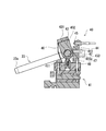
- FIG. 6 is a diagram for explaining a probe antenna mounting structure according to the embodiment (1).
- FIG. 7 is a view for explaining the mounting structure of the probe antenna according to the embodiment (2).
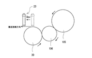
- FIG. 8 is a diagram conceptually illustrating the retraction operation of the probe antenna when the cigarette transported on the inspection drum according to the embodiment collides with the probe antenna.
- FIG. 9 is a diagram conceptually illustrating another retreat operation example of the probe antenna when the cigarette transported on the inspection drum according to the embodiment collides.
- FIG. 10 is a diagram illustrating another arrangement example of the probe antennas according to the embodiment.
- FIG. 11 is a diagram illustrating a modified example of the mounting structure for components near the transport path according to the embodiment.
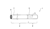
- FIG. 2 is a diagram showing the cigarette 1.
- the cigarette 1 is a cigarette with a filter including a cigarette rod 2 and a filter 4 connected to one end of the cigarette rod 2 via a chip paper 3.
- the filter 4 is obtained by winding a filter material made of a fiber bundle of cellulose acetate, for example, with a wrapping paper, and a capsule 5 is inserted in the filter material.
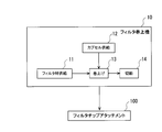
- the filter 4 is wound up by the filter hoisting machine 10.
- the tobacco rod 2 is formed by winding a tobacco cut 6 with a tobacco wrapping paper 7 and forming it into a cylindrical shape (bar shape).
- the capsule 5 is obtained by enclosing a liquid fragrance inside the shell.
- fragrances include menthol, lavender, cinnamon, cardamom, celery, clove, cascarilla, nutmeg, sandalwood, bergamot, geranium, honey essence, rose oil, vanilla, lemon, orange, mint, cinnamon, caraway, cognac,
- fragrances include, but are not limited to, essential oils such as jasmine, chamomile, kasha, ylang ylang, sage, spearmint, fennel, himent, ginger, anise, coriander, coffee and the like.
- the capsule 5 is inserted into the filter material included in the filter 4, but a cavity (cavity) is formed in the filter 4, and the capsule 5 is disposed in the cavity. Also good.
- the capsule 5 corresponds to a predetermined arrangement in the present invention.
- positioned in a smoking article activated carbon, the thread
- the filter hoisting machine 10 is an apparatus that manufactures the filter 4 of the cigarette 1.
- the filter material which is a fiber bundle of cellulose acetate is supplied in the filter material supply process 11
- the capsule 5 is supplied to the filter material in the capsule supply process 12, and the capsule 5 is inserted into the filter material.
- the filter material into which the capsules 5 are inserted is wound into a rod shape with a web.
- the cutting step 14 the filter rod is cut into predetermined lengths using a cutter (not shown), and a filter rod containing the capsule 5 is obtained.
- the filter rod manufactured by the filter hoisting machine 10 is sent to the filter chip attachment 16.
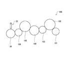
- FIG. 3 is a diagram schematically showing a partial configuration of the filter chip attachment 100 according to the embodiment.
- the filter chip attachment 100 is connected to a cigarette hoisting machine (not shown) and the filter hoisting machine 10.
- the filter chip attachment 100 has a plurality of drum rows, and the various drums shown in FIG. 3 show some of the plurality of drum rows included in the filter chip attachment 100.
- the filter chip attachment 100 receives a double cigarette rod DS having a length (double length) of two cigarette rods 2 of the cigarette 1 shown in FIG. 2 from a cigarette hoist (not shown) and conveys it. In the process, two single tobacco rods S are cut. Thereafter, these two single tobacco rods S are separated in the axial direction to form a cigarette row.
- the filter chip attachment 100 includes a hopper (not shown), and stores a large number of filter rods received from the filter hoisting machine 10 in the hopper.
- the filter rod sent from the filter hoisting machine 10 is a filter rod which has the length (4 times length) of the four filters 4 shown in FIG. 2, for example.
- the filter chip attachment 100 has a plurality of drum rows.
- the filter plugs FP are supplied to the hopper drum 101 after being aligned in a line through a grading process in the transport direction.
- the cigarette row of the filter chip attachment 100 has an interval in which the filter plug FP can be received between each single tobacco rod S, and is supplied to the hopper drum 101 while maintaining this interval. At this time, the cigarette row receives the filter plugs FP between the single cigarette rods S and is arranged on the same axis as the filter plugs FP.
- the hopper drum 101 has a rod holding groove (not shown), and is rotated and conveyed in a state where the single tobacco rod S-2 double-length filter plug FP and the single tobacco rod S are arranged in this order. Further, the hopper drum 101 includes a pair of floating disks (not shown).
- each single cigarette rod S is sandwiched between the floating disks on both sides, and the distance between them is reduced in the axial direction. Thereby, the intermediate product I of the double filter cigarette in which the filter plug FP is positioned between the two single tobacco rods S is formed.
- the filter chip attachment 100 applies a paste to one side of a long chip paper web (not shown) while continuously feeding it, and then cuts the web into chip paper pieces C of a predetermined length from the top.
- the cut piece of chip paper C is pasted around the filter plug FP on the hopper drum 101 and the two single cigarette rods S positioned on both sides thereof, that is, the intermediate product I of the double filter cigarette.
- the drum 102 is supplied.
- the intermediate product I of the double filter cigarette rolls on the outer peripheral surface thereof, and the chip paper piece C follows the rolling to thereby surround the intermediate product I of the double filter cigarette. Wrap around.
- the filter paper FP and the base end portion of the single cigarette rod S positioned on both sides of the filter plug FP are glued so that the chip paper piece C integrally wraps around the filter plug FP.
- the double filter cigarette (double winding) is transferred from the rolling drum 102 to the checking drum 103 as the next process.
- a ventilation check of the double filter cigarette is performed, and it is inspected whether the wrapping paper is torn or the like. Defective products that do not pass the inspection are excluded from the checking drum 103.
- the double filter cigarette that has passed the ventilation test is transferred from the checking drum 103 to the cutting drum 104.
- the double filter cigarette is cut at a central position in the axial direction by a cutting knife (not shown) and separated into a pair of filter cigarettes.
- the pair of filter cigarettes here is a cigarette 1 having a length of one as shown in FIG.
- the cigarette 1 cut by the cutting drum 104 is transferred to the turning drum 105, and one row of the cigarette 1 is reversed on the turning drum 107.
- the cigarettes 1 are transferred from the turning drum 107 to the intermediate drum 106 in a state where the directions are aligned in a line, and further sent one by one from the intermediate drum 106 to the inspection drum 30.
- a quality inspection regarding the capsule 5 arranged in the filter 4 is performed using the capsule inspection apparatus shown in FIG. 4.
- the capsule inspection device 200 includes a control device 20, a noise source 21, a low-pass filter 22, a probe antenna 23, a circulator 24, a detector 25, an amplifier filter 26, and the like.
- the control device 20 is a computer that executes various processes executed by the capsule inspection device 200.
- the probe antenna 23 is an antenna used for the inspection regarding the quality of the arrangement state of the capsule 5 incorporated in the filter 4 of the cigarette 1, and corresponds to the antenna unit in the present invention.
- the inspection drum 30 is a transport device that can simultaneously transport a plurality of cigarettes 1 in a sucked (suction) state. More specifically, the inspection drum 30 includes a drum body 31 that is a metal cylindrical member. The drum body 31 is rotationally driven by a motor (not shown) in the direction of the white arrow shown in FIG. On the outer peripheral surface 31 a of the drum body 31, a plurality of holding grooves 32 extending in a direction parallel to the rotation axis of the drum body 31 are provided at regular intervals in the circumferential direction of the drum body 31.
- the holding groove 32 has a hollow shape that can partially receive the cigarette 1, and can hold the received cigarette 1 in a sucked (suction) state by receiving supply of suction air.
- the inspection drum 30 conveys the cigarette 1 on the conveyance path in a state where the cigarette 1 is sucked and held in each holding groove 32 in the drum main body 31, and sequentially delivers the cigarette 1 to, for example, a subsequent drum.
- 5 shows a state in which the cigarette 1 is accommodated only in the three holding grooves 32 for drawing, but in actuality, the drum is conveyed with the cigarette 1 being accommodated in each holding groove 32. .
- a circulator 24 is connected to the probe antenna 23. Further, the inspection electromagnetic wave supplied from the noise source 21 passes through the low-pass filter 22 and is generated in the circulator 24, and the inspection electromagnetic wave is input to the circulator 24. Preferably, an electromagnetic wave having an oscillation frequency of 22 GHz to 40 GHz generated by the noise source 21 is passed through the low pass filter 22 to generate an inspection electromagnetic wave of 20 to 30 GHz. As another example, the frequency of the inspection electromagnetic wave input to the circulator 24 may belong to 10 to 100 GHz.
- a detector 25 is connected to the circulator 24 at its output.
- the detector 25 takes out an electrical reflection signal corresponding to a reflected electromagnetic wave, which will be described later, and then performs predetermined electrical processing such as amplification and filtering on the reflection signal by the amplifier filter 26, and sends the reflected signal to the control device 20. Is delivered.
- the probe antenna 23 has a long and narrow antenna casing, and is arranged so that the tip thereof faces the filter 4 to be inspected.
- the probe antenna 23 is configured to be irradiated with an inspection electromagnetic wave from an antenna portion 23a disposed at the tip.
- the inspection electromagnetic wave irradiated from the antenna unit 23a is reflected by the filter 1, and the reflected electromagnetic wave is received by the antenna unit 23a again. Therefore, in the capsule inspection apparatus 200 shown in FIG. 4, both the inspection electromagnetic wave and the reflected electromagnetic wave are conveyed through the probe antenna 23. That is, the inspection electromagnetic wave transmission part and the reflected electromagnetic wave reception part are arranged on the same side with respect to the filter 4.
- the probe antenna 23 is installed close to the inspection drum 30 at a position facing the inspection drum 30 that is rotationally driven.
- the drum body 31 of the inspection drum 30 is rotatably supported on the drum drive shaft, and a rotary encoder 33 is connected via the drum drive shaft.
- a rotary encoder 33 is driven by the drum drive shaft, and a pulse signal obtained therefrom and a drum clock pulse (DCP) corresponding to each cigarette generated by the hoisting machine are delivered to the control device 20 of the capsule inspection device. It has become so. Therefore, based on the pulse signal and the DCP, the capsule inspection apparatus 200 can determine which filter 4 of the cigarette 1 being transported on the transport path by the inspection drum 30 is subjected to the inspection process. Is possible.
- the inspection process is performed by executing a predetermined control program in the control device 20.
- the total number of cigarettes 1 that are sequentially rotated and conveyed by the inspection drum 30 is the inspection target, but is not limited thereto.
- the inspection process will be described in detail. First, whether or not the filter 4 of the cigarette 1 to be inspected has reached the inspection region, that is, the filter 4 is irradiated with the inspection electromagnetic wave from the antenna portion 23a of the probe antenna 23. It is determined whether or not the region has been reached. As described above, the control device 20 can grasp the relative position of the cigarette 2 with respect to the inspection area by using the pulse signal from the rotary encoder 33 and thus the cigarette 1 conveyed by the inspection drum 30. It can be determined that the filter 4 has reached the inspection region.
- the inspection electromagnetic wave is irradiated to the filter 4 from the antenna portion 23a of the probe antenna 23. Then, the reflected electromagnetic wave is received by the antenna unit 23a.
- the reflected electromagnetic wave received by the antenna unit 23a of the probe antenna 23 is delivered to the detector 25 through the circulator 24, and the detector 25 takes out an electrical reflection signal corresponding to the reflected electromagnetic wave.
- predetermined electrical processing such as amplification and filtering is performed on the reflected signal by the amplifier filter 26, and the electrical reflected signal corresponding to the reflected electromagnetic wave is delivered to the control device 20.
- the control device 20 acquires the received intensity of the reflected electromagnetic wave based on the delivered reflected signal. And the control apparatus 20 performs the determination regarding the arrangement
- the capsule inspection apparatus it is inspected whether the capsule 5 incorporated in the filter 4 has an abnormality, more specifically, whether the capsule 5 has a defect such as a crack. Inspection can be suitably performed.
- the cigarette 1 having the filter 4 determined to be abnormal can be removed, for example, on the inspection drum 30 or at a position subsequent to the inspection drum 30 in the transport path of the cigarette 1.
- the cigarette 1 determined as a defective product by the capsule inspection apparatus 200 is configured to be excluded by a known exclusion unit while being transported on the inspection drum 30.
- an air supply passage through which air is supplied from an air source (not shown) communicates with the bottom of each holding groove 32 in the inspection drum 30.
- an electromagnetic on-off valve is provided between the air source and the air supply passage. (Not shown) is provided.
- the electromagnetic open / close valve is controlled by the control device 20, and the cigarette 1 determined to be defective by the capsule inspection device 200 is ejected from the corresponding air supply passage while being conveyed on the inspection drum 30.
- the cigarette 1 is dropped from the holding groove 32 of the inspection drum 30 by the air force.
- the quality of the cigarette 1 (filter 4) is inspected in the inspection drum 30 located at the subsequent stage of the turning drum 107 in the filter chip attachment 100, so that one capsule inspection device 200 performs the total number of filters. 4 inspections are possible. Further, since the cigarette 1 after being cut by the final cutting drum 106 is inspected, there is an advantage that the waste of the raw material is less than when the product is excluded in the double filter cigarette state.
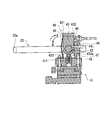
- FIG. 6 is a view for explaining a mounting structure of the probe antenna 23 according to the embodiment.
- the probe antenna 23 is attached to the vicinity of the inspection drum 30 in the filter chip attachment 16 by the antenna attachment portion 40 shown in FIGS. 5 and 6.
- the antenna mounting portion 40 corresponds to the mounting portion in the present invention.
- the antenna mounting portion 40 includes a base main body 41 that is attached to the airframe that is a stationary part of the filter chip attachment 16, and a movable support portion 43 that is rotatably attached to the base main body 41 and holds the probe antenna 23.
- the movable support portion 43 includes a rotation shaft member 42 and can rotate within a predetermined angle range with respect to the base body 41 with the rotation shaft member 42 as a rotation center.
- the base body 41 is fixed by being fastened to the airframe (non-moving part) of the filter chip attachment 16.
- a sensor holding portion indicated by reference numeral 44 is fixed to the base body 41, and an antenna position detection sensor 45 is held by the sensor holding portion 44.
- the antenna position detection sensor 45 is a sensor that detects whether the probe antenna 23 is in a normal position or a retracted position, which will be described later, and corresponds to a detection unit in the present invention. The detection result of the antenna position detection sensor 45 is delivered to the control device 20.
- the spring plate member 46 is fixed to the base body 41 by, for example, screwing or the like, and urges the movable support portion 43 in the direction of arrow A in FIG.
- the side surface pressed by the spring plate member 46 is referred to as a pressed surface 431.
- a side surface of the movable support portion 43 opposite to the pressed surface 431 is referred to as a contact surface 432.
- the contact surface 432 is in contact with the contacted surface 441 for positioning of the holding portion 44, so that further rotation (rotation) in the arrow A direction is suppressed, and the probe antenna 23 is in the normal position. Is positioned. Note that the posture of the movable support portion 43 when the probe antenna 23 is held at the normal position shown in FIG. 6 is referred to as a “normal posture”.
- reference numeral 433 denotes a circumferential surface of the movable support portion 43.
- the circumferential surface 433 is provided with a recess (concave portion) 433a.
- the engagement body 47 is pressed against the recess 433 a by the spring body 48, so that the engagement body 47 is fitted into the recess 433 a of the movable support portion 43.
- the engagement body 47 is a sphere, but the shape is not particularly limited.
- the spring body 48 and the engagement body 47 are accommodated in an accommodation hole 411 provided on the base body 41 side.
- the movable support portion 43 is elastically biased (pressed) toward the A direction (see FIG. 6) by the biasing force (elastic force) of the spring plate member 46. Therefore, when a force larger than the biasing force of the spring plate member 46 acting on the movable support portion 43 acts in the direction opposite to the biasing force, the spring plate member 46 resists the biasing force (elastic force).
- the movable support portion 43 rotates in the B direction (see FIG. 6) about the rotation shaft member 42. In FIG. 7, the movable support portion 43 rotates from the normal posture in the B direction (see FIG.
- FIG. 6 shows a state when it exists in a retracted attitude
- the engagement body 47 is detached from the recess 433a of the movable support portion 43, and the circumferential surface 433 (general parts other than the recess 433a) in the movable support portion 43. ) Is brought into contact with the engagement body 47, and the engagement body 47 is pressed.
- the position of the probe antenna 23 in the state shown in FIG. 7, that is, the state in which the movable support portion 43 is in the retracted position is referred to as “retracted position”.
- the probe antenna 23 attached to the vicinity of the inspection drum 30 of the filter chip attachment 16 by the antenna attachment portion 40 configured as described above is normally disposed at a normal position shown in FIG.
- the antenna mounting portion 40 base body 41
- the probe antenna 23 is sequentially rotated and conveyed on the conveyance path of the inspection drum 30 while the filter 4 of the cigarette 1 passes through the vicinity of the antenna portion 23a.
- the distance between the antenna portion 23a and the filter 4 of the cigarette 1 conveyed by the inspection drum 30 when the probe antenna 23 is in the normal position is set to about several mm (for example, about 3 mm).
- an inspection process is performed to determine whether there is an abnormality such as a tear in the capsule 5 built in the filter 4 described above.
- a bent cigarette (hereinafter, “ In some cases, it may collide with the probe antenna 23 disposed close to the transport path of the cigarette 1. In addition, the cigarette 1 may collide with the probe antenna 23 even when the cigarette 1 does not have a defective portion such as a bend, but the cigarette 1 is not normally conveyed due to some factor.
- the cigarette 1 has been increased in speed as the cigarette 1 is manufactured with higher performance. Therefore, in the conventional cigarette manufacturing apparatus, the cigarette may collide with a nearby part of the transport path such as a probe antenna arranged close to the transport path of the cigarette. There was concern that the parts would be damaged.
- the conveyance path proximity component when the cigarette 1 which is a smoking article collides with the conveyance path vicinity component, the conveyance path proximity component is retracted from the normal position.
- the evacuation means for evacuating is provided. More specifically, the retracting means includes a movable support portion 43 having a rotating shaft member 42 and a spring plate member 46 (for biasing the movable support portion 43 to hold the probe antenna 23 in a normal position ( This is realized by an urging member.
- the cigarette 1 transported by the inspection drum 30 (drum body 31) is caused by some factor such as bending of the cigarette 1 or transport trouble.
- the movable support portion 43 resists the urging force (pressing force) of the spring plate member 46 due to the impact at the time of collision, as shown in FIG. It rotates in the B direction. That is, the posture of the movable support portion 43 is changed from the normal posture (see FIG. 6) to the retracted posture (see FIG. 7). In other words, the probe antenna 23 retreats from the normal position shown in FIG.
- FIG. 8 is a diagram conceptually illustrating the retraction operation of the probe antenna 23 when the cigarette 1 being transported on the inspection drum 30 in the embodiment collides with the probe antenna 23.
- the movable support portion 43 resists the urging force (pressing force) of the spring plate member 46 due to the impact at the time of the collision.
- the probe antenna 23 is retracted from the normal position to the retracted position. Thereby, it can suppress that an excessive load acts on the probe antenna 23 (antenna part 23a), and can suppress damage to the probe antenna 23 (antenna part 23a).
- the probe antenna 23 corresponds to a component near the transport path in the present invention.
- the antenna mounting portion 40 checks the retract direction Dev (see FIG. 5) of the probe antenna 23 when the probe antenna 23 is retracted from the normal position to the retracted position. It is set so as to correspond to the transport direction of the cigarette 1 by the drum 30 for use. That is, the retraction direction Dev of the probe antenna 23 is matched with the direction of releasing (reducing) the impact (load) when the cigarette 1 collides with the probe antenna 23. Accordingly, the impact (load) when the cigarette 1 collides with the probe antenna 23 can be suitably escaped (reduced) while the probe antenna 23 can be retracted to the retracted position, and the probe antenna 23 can be damaged. Can be suitably suppressed.
- the state in which the retract direction Dev of the probe antenna 23 corresponds to the transport direction of the cigarette 1 is not limited to the transport direction of the cigarette 1 and the retract direction Dev of the probe antenna 23 being parallel.
- the conveyance direction of the cigarette 1 in the inspection drum 30 coincides with the circumferential direction of the drum main body 31 and is conveyed along the arcuate conveyance path.
- the retraction direction Dev of the probe antenna 23 also retreats from the normal position to the retreat position through an arc orbit centered on the rotation shaft member 42.
- the tangential direction of the arcuate conveyance path of the inspection drum 30 that conveys the cigarette 1 (hereinafter referred to as “conveyance tangential direction”) and the arc when the probe antenna 23 is retracted from the normal position to the retracted position.
- the tangential direction of the orbit coincides (see FIG. 8).
- such a mode also corresponds to the retraction direction Dev of the probe antenna 23 corresponding to the transport direction of the cigarette 1.
- the tangential direction (conveyance tangential direction) of the circular arc track of the conveyance drum 30 that conveys the cigarette 1 and the tangential direction (retraction direction Dev) of the circular arc track when the probe antenna 23 is retreated from the normal position to the retraction position. )) Is not excessively different (for example, if the angle formed by both tangential directions is 90 ° or less), it can be said that the retract direction Dev of the probe antenna 23 corresponds to the transport direction of the cigarette 1.
- FIG. 9 is a diagram conceptually showing another example of retreating operation of the probe antenna 23 when the cigarette 1 transported through the inspection drum 30 according to the embodiment collides.
- the probe antenna 23 is slid in the tangential direction of the circular arc track when the cigarette 1 is transported on the inspection drum 30 by a driving means (not shown), so that the retraction direction Dev of the probe antenna 23 is set. It is made to correspond to the conveyance tangent direction of the cigarette 1.
- the tangential direction (conveyance tangential direction) of the circular arc trajectory of the conveyance drum 30 that conveys the cigarette 1 and the retraction direction Dev when the probe antenna 23 slides away from the normal position to the retraction position should not be excessively different.
- the angle between the two is 90 ° or less
- the retracting direction Dev of the probe antenna 23 corresponds to the transport direction of the cigarette 1.
- the probe antenna 23 can be retracted to the retracted position while releasing (reducing) the impact (load) when the cigarette 1 collides with the probe antenna 23.
- the probe antenna 23 is installed in the vicinity of the conveyor that transports the cigarette 1, and the quality inspection using the probe antenna 23 is performed on the filter 4 of the cigarette 1 that is sequentially transported along the linear transport path by the conveyor. May be performed.
- the traveling direction of the cigarette 1 being conveyed by the conveyor corresponds to the retracting direction Dev of the probe antenna 23.
- the angle formed by the retract direction Dev in which the probe antenna 23 is retracted from the normal position to the retract position and the transport direction (traveling direction) of the cigarette 1 may be 90 ° or less.
- the urging force of the spring plate member 46 always acts in the direction of holding the movable support portion 43 in the normal posture. That is, the urging force of the spring plate member 46 always acts on the movable support portion 43 in the direction in which the movable support portion 43 is shifted from the retracted posture to the normal posture (the direction of arrow A in FIG. 6). Therefore, when the load on the probe antenna 23 caused by the collision of the cigarette 1 disappears, the probe antenna 23 can be automatically returned from the retracted position to the normal position (in this case, the return direction Dre shown in FIG. 5). The probe antenna 23 rotates).
- the probe antenna 23 can be quickly returned from the retracted position to the normal position. According to this, there exists an effect that the test
- the engagement body 47 is fitted in the recess 433a of the movable support portion 43 by the spring body 48 accommodated in the accommodation hole 411 of the base body 41.
- the movable support portion 43 is pressed toward the rotating shaft member 42. According to this, it is possible to make it difficult to release the holding state of the probe antenna 23 at the normal position when mechanical vibration or the like is applied.
- the antenna mounting portion 40 is provided with an antenna position detection sensor 45 in a sensor holding portion 44 provided integrally with the base main body 41, and it is determined whether the probe antenna 23 is in a normal position or a retracted position. It is detected by the detection sensor 45.
- the antenna position detection sensor 45 may be, for example, a distance measurement (distance measurement) sensor, and measures a separation distance from the contact surface 432 using the contact surface 432 of the movable support portion 43 as a measurement target surface.
- a distance measurement distance measurement
- the antenna position detection sensor 45 is configured so that the movable support 43 is in the normal posture, that is, the probe antenna 23 is in the normal position when the measured separation distance from the antenna position detection sensor 45 to the contact surface 432 matches the predetermined dimension. It is determined that On the other hand, when the distance between the measured antenna position detection sensor 45 and the contact surface 432 is excessively larger than the predetermined dimension, the antenna support sensor 45 is retracted, that is, the probe antenna 23 is It is determined that it is in the retracted position. In this way, the antenna position detection sensor 45 can detect whether or not the probe antenna 23 is in the normal position.
- the detection signal of the antenna position detection sensor 45 is input to the control device 20.
- the control device 20 that has acquired a detection signal (hereinafter referred to as “antenna position detection signal”) from the antenna position detection sensor 45 uses an exclusion unit (not shown) (for example, compressed air) based on the antenna position detection signal.
- exclusion unit for example, compressed air
- the control device 20 Based on the pulse signal obtained from the rotary encoder 33, the drum clock pulse (DCP) corresponding to each cigarette, and the antenna position detection signal, the control device 20 performs normal inspection of the capsule 5 by the capsule inspection device. It is possible to identify a cigarette 1 that has not been processed (hereinafter referred to as “a cigarette that has not been subjected to a normal inspection process”). Therefore, the control device 20 excludes the cigarette that has not been subjected to the normal inspection process specified in this way by using the above-described exclusion unit in the inspection drum 30.
- the compressed air is ejected from the air supply passage communicating with the bottom of the holding groove 32 where the normal inspection processing non-executed cigarette is sucked and held, and the normal inspection non-execution cigarette is dropped from the inspection drum 30.
- the control device 20 may stop the filter chip attachment 16 while the probe antenna 23 is retracted to the retracted position.
- the relative position of the probe antenna 23 (antenna portion 23a) with respect to the transport drum 30 is not particularly limited.
- the probe antenna 23 (antenna portion 23 a) may be disposed above the inspection drum 30.
- the probe antenna 23 is provided in the vicinity of the transport path (transport track) of the cigarette 1 in the intermediate drum 106.
- the probe antenna 23 (antenna portion 23a) is arranged above the drum (inspection drum 30), a conveyance failure occurs compared to the case where it is arranged below the drum (intermediate drum 106).
- the bent cigarette 1 is easily clogged. This is because when the probe antenna 23 (antenna portion 23a) is disposed below the drum (intermediate drum 106), the cigarette 1 that collides with the probe antenna 23 easily falls from the drum.
- the probe antenna 23 (antenna portion 23a) may be inevitably disposed above the inspection drum 30 due to space limitations.
- the cigarette 1 is located between the inspection drum 30 and the probe antenna 23. Inconvenience such as clogging can be suitably suppressed, and the effect becomes even more remarkable.
- the spring plate member 46 is employed as an example of the urging member, but is not limited thereto. It is sufficient to have a function of holding the probe antenna 23 as a component in the vicinity of the conveyance path in a normal position by urging the movable support portion 43. For example, the movable support portion 43 is pulled in the direction A in FIG. Also good.
- the probe antenna 23 when the cigarette 1 collides with the probe antenna 23 using the mechanical mechanism, the probe antenna 23 is retracted from the normal position to the retracted position.
- the probe antenna 23 may be retracted from the normal position to the retracted position by controlling a driving device (not shown) such as an actuator by the control device 20.
- the control device 20 causes the drive device (corresponding to the drive means) such as an actuator to rotate the movable support portion 43 from the normal posture to the retracted posture when the cigarette 1 collides with the probe antenna 23.
- the probe antenna 23 may be retracted from the normal position to the retracted position.
- the control device 20 controls the drive device such as an actuator to rotate the movable support portion 43 from the retracted posture to the normal posture.
- the probe antenna 23 may be returned from the retracted position to the normal position.
- the movable support part 43 is supporting the probe antenna 23 so that rotation is possible, you may support the probe antenna 23 so that sliding is possible between a regular position and a retracted position.
- the probe antenna 23 is retracted from the normal position to the retracted position, and returned from the retracted position to the normal position, mainly using a mechanical mechanism called a spring plate member 46. According to this, there also exists an advantage that the control content can be simplified by the whole apparatus called the manufacturing apparatus of the cigarette 1.
- the present invention is not limited to this.
- the mounting structure according to the present embodiment may be applied.
- the present invention relates to a probe antenna 23 that inspects the quality of the capsule 5 incorporated in the filter 4 of the cigarette 1 as an example of a component near the conveyance path that is disposed near the conveyance path of the smoking article.
- FIG. 11 is a view showing a modification of the attachment structure for the parts near the conveyance path according to the embodiment.
- the aspect which inspects the quality of the capsule 5 incorporated in the filter rod FR by the fixed interval in the filter hoisting machine 10 is demonstrated.
- FIG. 11 is a view showing a modification of the attachment structure for the parts near the conveyance path according to the embodiment.
- a filter rod FR having a long rod shape is continuously fed out from the filter winding upper portion 110 while the filter winding paper is wound around the filter material in which the capsule 5 is inserted.
- the long rod-shaped filter rod FR is cut into a fixed length at the cutting portion 120. For example, after the long filter rod FR is cut to a length of 4 times in the cutting unit 120, the 4 times longer filter rod may be supplied to the filter chip attachment 100.
- the probe antenna 23 of the capsule inspection apparatus 200 is installed close to the conveyance path of the filter rod FR between the filter winding upper part 110 and the cutting part 120.
- the probe antenna 23 is held, for example, by the antenna mounting portion 40 described with reference to FIGS. 5 to 7, and the antenna mounting portion 40 may be fixed to the body (non-moving portion) of the filter hoisting machine 10.
- the filter rod FR is conveyed along a linear conveyance path. As described above, it is assumed that the filter rod FR collides with the probe antenna 23 for some reason when manufacturing the filter in the filter hoist 10. In this case, the probe antenna 23 is properly connected by the antenna mounting portion 40.
- the probe antenna 23 is retracted from the normal position to the retracted position by changing the posture of the movable support portion 43 from the normal posture to the retracted posture due to an impact when the filter rod FR collides with the probe antenna 23. .
- the posture of the movable support portion 43 is returned from the retracted posture to the normal posture, and the probe antenna 23 is moved from the retracted position to the normal position. Can be restored.
- the movable support part 43 may support the probe antenna 23 slidably along the conveyance direction of the filter rod FR, and the probe antenna 23 may be supported in the conveyance direction of the filter rod FR.
- the retreat direction Dev may be matched.
- the retraction of the probe antenna 23 from the normal position to the retraction position and the return from the retraction position to the normal position may be realized by using a mechanical mechanism including the movable support portion 43 and the spring plate member 46. Alternatively, it may be realized by controlling driving means such as an actuator with electric power.
- the probe antenna 23 of the capsule inspection apparatus 200 is disposed between the filter upper part 110 and the cutting unit 120, but the probe antenna 23 may be disposed after the cutting unit 120. .
- the application of the mounting structure for the parts near the conveyance path according to the embodiment to the filter hoist 10 is not limited to the above-described modification.
- the present invention is applied to the glue nozzle mounting structure when the glue nozzle for discharging the adhesive paste to the web is disposed close to the web.
- a glue nozzle for discharging a sticking glue to the cigarette paper in a cigarette rod forming section of a cigarette winder (not shown) may be adopted as a component near the conveyance path, and the mounting structure according to the present invention may be applied.
- examples of components near the transport path include a glue nozzle, a suction port for removing dust from the transported object, a compressed air nozzle, a laser aperture device, and the like.
Landscapes
- Manufacturing Of Cigar And Cigarette Tobacco (AREA)
Abstract
L'invention concerne une technique faisant que, même si un produit à fumer transporté sur un trajet de transport dans un appareil de production de produit à fumer entre en collision avec un élément à proximité du trajet de transport qui est disposé à proximité du trajet de transport, il soit empêché que l'élément à proximité du trajet de transport ne soit endommagé. Cette structure est destinée au montage d'un élément à proximité du trajet de transport prédéterminé qui doit être monté dans un appareil de production de produit à fumer et disposé à proximité d'un trajet de transport pour transporter un produit à fumer dans l'appareil de production. La structure comprend : une partie de montage permettant de monter l'élément à proximité du trajet de transport sur l'appareil de production de sorte que l'élément à proximité du trajet de transport soit disposé au niveau d'une position normale prédéterminée ; et un moyen de retrait permettant de retirer l'élément à proximité du trajet de transport de la position normale vers une position de retrait prédéterminée lorsque le produit à fumer entre en collision avec l'élément à proximité du trajet de transport.
Priority Applications (1)
| Application Number | Priority Date | Filing Date | Title |
|---|---|---|---|
| PCT/JP2016/064625 WO2017199341A1 (fr) | 2016-05-17 | 2016-05-17 | Structure destinée au montage d'un élément à proximité d'un trajet de transport dans un appareil de production de produit à fumer |
Applications Claiming Priority (1)
| Application Number | Priority Date | Filing Date | Title |
|---|---|---|---|
| PCT/JP2016/064625 WO2017199341A1 (fr) | 2016-05-17 | 2016-05-17 | Structure destinée au montage d'un élément à proximité d'un trajet de transport dans un appareil de production de produit à fumer |
Publications (1)
| Publication Number | Publication Date |
|---|---|
| WO2017199341A1 true WO2017199341A1 (fr) | 2017-11-23 |
Family
ID=60325107
Family Applications (1)
| Application Number | Title | Priority Date | Filing Date |
|---|---|---|---|
| PCT/JP2016/064625 Ceased WO2017199341A1 (fr) | 2016-05-17 | 2016-05-17 | Structure destinée au montage d'un élément à proximité d'un trajet de transport dans un appareil de production de produit à fumer |
Country Status (1)
| Country | Link |
|---|---|
| WO (1) | WO2017199341A1 (fr) |
Citations (6)
| Publication number | Priority date | Publication date | Assignee | Title |
|---|---|---|---|---|
| EP0792576A2 (fr) * | 1996-03-01 | 1997-09-03 | B. Strautmann & Söhne GmbH & Co. | Dispositif de coupe pour tiges et feuilles |
| JP2001275641A (ja) * | 2000-03-30 | 2001-10-09 | Japan Tobacco Inc | フィルタシガレットの検査排除装置 |
| JP2006174835A (ja) * | 2004-12-23 | 2006-07-06 | G D Spa | 紙巻たばこの群を移送し検査するための装置 |
| JP2006234760A (ja) * | 2005-02-28 | 2006-09-07 | Japan Steel Works Ltd:The | シート厚み計測装置 |
| JP2012533295A (ja) * | 2009-07-15 | 2012-12-27 | インターナショナル タバコ マシーネリー ポーランド エスピー. ゼット オー.オー. | マルチセグメントフィルタの製造プロセスにおけるフィルタセグメントの安全移送方法 |
| JP2013088190A (ja) * | 2011-10-14 | 2013-05-13 | Tokyo Seimitsu Co Ltd | タッチプローブ |
-
2016
- 2016-05-17 WO PCT/JP2016/064625 patent/WO2017199341A1/fr not_active Ceased
Patent Citations (6)
| Publication number | Priority date | Publication date | Assignee | Title |
|---|---|---|---|---|
| EP0792576A2 (fr) * | 1996-03-01 | 1997-09-03 | B. Strautmann & Söhne GmbH & Co. | Dispositif de coupe pour tiges et feuilles |
| JP2001275641A (ja) * | 2000-03-30 | 2001-10-09 | Japan Tobacco Inc | フィルタシガレットの検査排除装置 |
| JP2006174835A (ja) * | 2004-12-23 | 2006-07-06 | G D Spa | 紙巻たばこの群を移送し検査するための装置 |
| JP2006234760A (ja) * | 2005-02-28 | 2006-09-07 | Japan Steel Works Ltd:The | シート厚み計測装置 |
| JP2012533295A (ja) * | 2009-07-15 | 2012-12-27 | インターナショナル タバコ マシーネリー ポーランド エスピー. ゼット オー.オー. | マルチセグメントフィルタの製造プロセスにおけるフィルタセグメントの安全移送方法 |
| JP2013088190A (ja) * | 2011-10-14 | 2013-05-13 | Tokyo Seimitsu Co Ltd | タッチプローブ |
Similar Documents
| Publication | Publication Date | Title |
|---|---|---|
| JP5923237B2 (ja) | 煙草加工産業のフィルタのカプセル監視とカプセル位置調整 | |
| EP1011351B1 (fr) | Machine de fabrication de cigarettes comprenant un systeme de controle de bandes | |
| JP6340009B2 (ja) | 喫煙具に付随する喫煙具フィルタの分析システム及び関連方法 | |
| EP1330961B1 (fr) | Procédé de détection et d'élimination de corps étrangers dans un courant de tabac | |
| CN103504473B (zh) | 对烟草加工业的材料条的条异质性进行识别的方法和装置 | |
| JP6253908B2 (ja) | 繊維状材料で作製された長尺要素の検査方法 | |
| US20170112185A1 (en) | A smoking article assembly machine | |
| PL209155B1 (pl) | Sposób eksploatacji maszyny przemysłu tytoniowego, sposób ponownego uruchamiania maszyny do produkcji ciągłej, sposób automatycznego rozruchu maszyny do produkcji ciągłej, sposób opróżniania maszyny do produkcji ciągłej oraz urządzenie do doprowadzania co najmniej jednego pasa osłonkowego do elementu doprowadzającego, układ do doprowadzania co najmniej jednego pasa osłonkowego i maszyna do produkcji ciągłej | |
| US11225390B2 (en) | Method and apparatus for feeding and splicing sheet of material wound in a bobbin | |
| CN101828767B (zh) | 旋转盘刀、安装旋转盘刀的方法和拆除旋转盘刀的方法 | |
| CN109564192B (zh) | 用于识别制品中的导电元件的测量装置和方法及用于制造烟草加工业制品的机器 | |
| WO2013146528A1 (fr) | Dispositif de montage de filtre | |
| CN102626258A (zh) | 烟草加工行业的棒状制品的制造 | |
| US7784356B2 (en) | Inspection systems and methods for multi-segment products | |
| JP2000014376A (ja) | シガレット用フィルタロッドの検査装置及びその検査方法 | |
| JPH06197746A (ja) | シガレットのルース端を識別するための点検方法及び装置 | |
| CN113924253A (zh) | 用于生产或包装消费品、特别是烟草行业的消费品的自动机器中的控制和/或识别方法 | |
| WO2017199341A1 (fr) | Structure destinée au montage d'un élément à proximité d'un trajet de transport dans un appareil de production de produit à fumer | |
| EP3238552B1 (fr) | Appareil d'inspection de filtre | |
| EP3806666B1 (fr) | Unité de détection et procédé pour l'industrie du tabac | |
| JP2025084853A (ja) | エアロゾル供給システム用消耗品を製造するための装置および方法 | |
| JP7042985B2 (ja) | ロッド状たばこ製品の検査装置 | |
| JP5751653B2 (ja) | フィルタ装着装置 | |
| KR20190002580A (ko) | 담배 산업 제품 제조 장치를 위한 드럼 | |
| JPS629302B2 (fr) |
Legal Events
| Date | Code | Title | Description |
|---|---|---|---|
| NENP | Non-entry into the national phase |
Ref country code: DE |
|
| 121 | Ep: the epo has been informed by wipo that ep was designated in this application |
Ref document number: 16902361 Country of ref document: EP Kind code of ref document: A1 |
|
| 122 | Ep: pct application non-entry in european phase |
Ref document number: 16902361 Country of ref document: EP Kind code of ref document: A1 |
|
| NENP | Non-entry into the national phase |
Ref country code: JP |