WO2017199376A1 - Climatiseur - Google Patents
Climatiseur Download PDFInfo
- Publication number
- WO2017199376A1 WO2017199376A1 PCT/JP2016/064754 JP2016064754W WO2017199376A1 WO 2017199376 A1 WO2017199376 A1 WO 2017199376A1 JP 2016064754 W JP2016064754 W JP 2016064754W WO 2017199376 A1 WO2017199376 A1 WO 2017199376A1
- Authority
- WO
- WIPO (PCT)
- Prior art keywords
- motor
- air conditioner
- correction value
- storage unit
- calculation unit
- Prior art date
- Legal status (The legal status is an assumption and is not a legal conclusion. Google has not performed a legal analysis and makes no representation as to the accuracy of the status listed.)
- Ceased
Links
Images


Classifications
-
- F—MECHANICAL ENGINEERING; LIGHTING; HEATING; WEAPONS; BLASTING
- F24—HEATING; RANGES; VENTILATING
- F24F—AIR-CONDITIONING; AIR-HUMIDIFICATION; VENTILATION; USE OF AIR CURRENTS FOR SCREENING
- F24F1/00—Room units for air-conditioning, e.g. separate or self-contained units or units receiving primary air from a central station
-
- F—MECHANICAL ENGINEERING; LIGHTING; HEATING; WEAPONS; BLASTING
- F24—HEATING; RANGES; VENTILATING
- F24F—AIR-CONDITIONING; AIR-HUMIDIFICATION; VENTILATION; USE OF AIR CURRENTS FOR SCREENING
- F24F11/00—Control or safety arrangements
- F24F11/70—Control systems characterised by their outputs; Constructional details thereof
- F24F11/72—Control systems characterised by their outputs; Constructional details thereof for controlling the supply of treated air, e.g. its pressure
- F24F11/74—Control systems characterised by their outputs; Constructional details thereof for controlling the supply of treated air, e.g. its pressure for controlling air flow rate or air velocity
-
- Y—GENERAL TAGGING OF NEW TECHNOLOGICAL DEVELOPMENTS; GENERAL TAGGING OF CROSS-SECTIONAL TECHNOLOGIES SPANNING OVER SEVERAL SECTIONS OF THE IPC; TECHNICAL SUBJECTS COVERED BY FORMER USPC CROSS-REFERENCE ART COLLECTIONS [XRACs] AND DIGESTS
- Y02—TECHNOLOGIES OR APPLICATIONS FOR MITIGATION OR ADAPTATION AGAINST CLIMATE CHANGE
- Y02B—CLIMATE CHANGE MITIGATION TECHNOLOGIES RELATED TO BUILDINGS, e.g. HOUSING, HOUSE APPLIANCES OR RELATED END-USER APPLICATIONS
- Y02B30/00—Energy efficient heating, ventilation or air conditioning [HVAC]
- Y02B30/70—Efficient control or regulation technologies, e.g. for control of refrigerant flow, motor or heating
Definitions
- the present invention relates to an air conditioner having a motor.
- the air conditioner has, for example, a motor that drives a blower, and the operation of the motor is controlled based on a control constant.
- a conventional air conditioner stores a plurality of control constants, and controls a motor by selecting a control constant suitable for the motor from the plurality of control constants (see, for example, Patent Document 1).
- the control constant which the conventional air conditioner has is a fixed value.
- Makers of air conditioners may develop new air conditioners that differ in part from existing air conditioners and share the remainder.
- a part of the above is, for example, a motor.
- the conventional motor in which the control constant suitable for the new motor included in the new air conditioner is included in the conventional air conditioner Even if it is similar to the control constant suitable for the conventional air conditioner, the control constant of the conventional air conditioner is a fixed value, so the control constant of the conventional air conditioner cannot be used, and is suitable for a new motor. Control constants must be stored in a new air conditioner.
- control constant includes a plurality of parameters, a problem may occur during development, so it takes a long time to determine a new control constant. Therefore, it is required to provide an air conditioner that can easily develop a future air conditioner.
- the motor included in the air conditioner deteriorates over time due to the use of the air conditioner, it is necessary to change the control constant suitable for the motor along with the deterioration over time, but the conventional air conditioner has Since the control constant is a fixed value, it is difficult to change the control constant in the conventional air conditioner, as in the case of developing a new air conditioner.
- the present invention has been made in view of the above, and an object of the present invention is to obtain an air conditioner that can easily develop a future air conditioner and can cope with aged deterioration of a motor.
- an air conditioner corresponds to a motor, a storage unit that stores a reference value, the reference value stored in the storage unit, and the motor. And calculating a control constant for controlling the motor using a correction value for correcting the reference value, and controlling the motor using the control constant calculated by the calculation unit And a control unit.
- the air conditioner according to the present invention can easily develop a future air conditioner and can cope with aged deterioration of a motor.
- Process drawing which shows a part of procedure of the manufacturing method of the air conditioner of Embodiment 1.
- the figure which shows that at least one part of the calculation part and control part which comprise the air conditioner of Embodiment 1 is a processing circuit.
- FIG. The flowchart which shows the procedure of the operation
- FIG. 1 is a diagram illustrating a configuration of an air conditioner 1 according to the first embodiment.
- the air conditioner 1 includes a first motor 2-1,..., An nth motor 2-n. “N” is an integer of 2 or more.
- the first motor 2-1,..., The nth motor 2-n drive a blower not shown in FIG.
- the first motor 2-1,..., The nth motor 2-n are components of the air conditioner 1 and are components other than the blower among the plurality of components not shown in FIG. It may be driven.
- the first motor 2-1,..., The nth motor 2-n are three-phase AC motors whose rotation is controlled by a three-phase AC voltage.
- the air conditioner 1 may have only the first motor 2-1. That is, the air conditioner 1 may have only one motor.
- the air conditioner 1 further includes a first position detection circuit 3-1, which detects the position of the shaft of the first motor 2-1.
- the first position detection circuit 3-1 is attached to the first motor 2-1.
- the first position detection circuit 3-1 has, for example, three Hall elements that detect a change in magnetic flux, and detects the position of the shaft of the first motor 2-1 using the three Hall elements.
- the first position detection circuit 3-1 outputs a High or Low voltage to the microcomputer 8 to be described later according to the detected position of the shaft of the first motor 2-1.
- the air conditioner 1 further includes an n-th position detection circuit 3-n that detects the position of the shaft of the n-th motor 2-n.
- the nth position detection circuit 3-n is attached to the nth motor 2-n.
- the n-th position detection circuit 3-n has, for example, three Hall elements that detect a change in magnetic flux, and detects the position of the axis of the n-th motor 2-n using the three Hall elements.
- a high or low voltage is output to the microcomputer 8 according to the position of the shaft.
- the air conditioner 1 detects a current flowing through the first motor 2-1 when the operation of the first motor 2-1 is controlled by the microcomputer 8, and supplies a voltage corresponding to the detected current to the microcomputer 8. It further has a first current detection circuit 4-1 to be applied. That is, the first current detection circuit 4-1 detects the amount of current when the first motor 2-1 is driven. Similarly, the air conditioner 1 detects the current flowing through the n-th motor 2-n when the operation of the n-th motor 2-n is controlled by the microcomputer 8, and sets the voltage corresponding to the detected current to the micro An n-th current detection circuit 4-n applied to the computer 8 is further included. That is, the nth current detection circuit 4-n detects the amount of current when the nth motor 2-n is driven.
- the air conditioner 1 includes a first gate circuit 5-1,..., An nth gate circuit 5-n, and a direct current that converts an alternating voltage applied from an alternating current power supply 50 outside the air conditioner 1 into a direct current voltage. And a power supply circuit 6.
- the first gate circuit 5-1 switches between a state where the DC voltage obtained by the DC power supply circuit 6 is applied to the first motor 2-1 and a state where it is not applied according to control by the microcomputer 8.
- the n-th gate circuit 5-n switches between applying and not applying the DC voltage obtained by the DC power supply circuit 6 to the n-th motor 2-n according to control by the microcomputer 8.
- the air conditioner 1 further includes a voltage detection circuit 7 that lowers the value of the DC voltage obtained by the DC power supply circuit 6 and applies a DC voltage having a value lower than the value of the DC voltage to the microcomputer 8.
- the microcomputer 8 operates based on the DC voltage applied by the voltage detection circuit 7.
- the microcomputer 8 controls the operations of the first gate circuit 5-1,..., The nth gate circuit 5-n to control the first motor 2-1,. Control. Specifically, as described above, the first position detection circuit 3-1 outputs a High or Low voltage to the microcomputer 8 according to the position of the axis of the first motor 2-1, so the microcomputer 8 Based on the voltage applied from the 1-position detection circuit 3-1, the rotation direction and rotation speed of the shaft of the first motor 2-1 are calculated. The microcomputer 8 controls the first motor 2-1 based on the calculated rotation direction and rotation speed.
- the microcomputer 8 calculates the rotational direction and rotational speed of the shaft of the n-th motor 2-n based on the voltage applied from the n-th position detection circuit 3-n, and calculates the calculated rotational direction and rotational speed.
- the n-th motor 2-n is controlled based on the speed.
- the microcomputer 8 has a first storage unit that stores a reference value that is a reference control constant for controlling a reference motor.
- the reference motor is a motor to which a position detection circuit is attached at an angle with a very small error from the designed angle, and is specified by the manufacturer. Details of the first storage unit will be described later with reference to FIG.
- the microcomputer 8 calculates a first control constant for controlling the first motor 2-1 using a first correction value and a reference value described later.
- the first correction value corresponds to the first motor 2-1, and is a value for correcting the reference value.
- the first correction value includes the angle of the first position detection circuit 3-1 attached to the first motor 2-1 with respect to the axis of the first motor 2-1 and the reference motor of the position detection circuit attached to the reference motor. It is the information of the quantity which specifies the difference with respect to the angle with respect to the axis.
- the microcomputer 8 calculates an nth control constant for controlling the nth motor 2-n using an nth correction value and a reference value, which will be described later.
- the nth correction value corresponds to the nth motor 2-n and is a value for correcting the reference value.
- the nth correction value includes the angle of the nth position detection circuit 3-n attached to the nth motor 2-n with respect to the axis of the nth motor 2-n and the reference motor of the position detection circuit attached to the reference motor. It is the information of the quantity which specifies the difference with respect to the angle with respect to the axis.
- the microcomputer 8 controls the first motor 2-1 using the calculated first control constant, and controls the nth motor 2-n using the calculated nth control constant.
- the first control constant and the nth control constant will be described later.
- the air conditioner 1 further includes a second storage unit 9 that stores the first correction value, ..., the nth correction value.
- the second storage unit 9 is, for example, a non-volatile memory that can store information even when power is not applied, and the information stored in the second storage unit 9 can be rewritten. That is, the first correction value,..., The nth correction value stored in the second storage unit 9 can be rewritten.
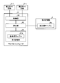
- FIG. 2 is a diagram illustrating a configuration of the microcomputer 8 in the air conditioner 1 according to the first embodiment. 2 also shows the first gate circuits 5-1,..., The nth gate circuit 5-n, and the second storage unit 9.
- the microcomputer 8 includes a first storage unit 81 that stores a reference value that is a reference control constant for controlling a reference motor. The reference value is used when calculating control constants for controlling the first motor 2-1,..., The nth motor 2-n.
- the first motor 2-1,..., The nth motor 2-n are three-phase AC motors whose rotation is controlled by a three-phase AC voltage.
- the phase angle varies depending on the rotational speed.
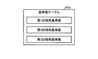
- the first storage unit 81 corresponds to the three types of rotational speeds, the first phase angle reference value, the second phase angle reference value, and the third phase.
- Three reference values of the corner reference value are stored.
- FIG. 3 is a diagram illustrating a reference value table 81a stored in the first storage unit 81 of the microcomputer 8 in the air conditioner 1 according to the first embodiment.
- the reference value table 81a includes the first phase angle reference value, the second phase angle reference value, and the third phase angle reference value.
- the first storage unit 81 stores only one reference value.
- the first storage unit 81 stores a reference value that is a reference control constant for controlling the reference motor. The reference value stored in the first storage unit 81 is determined at the time of manufacturing the air conditioner 1 and stored in the first storage unit 81.
- the microcomputer 8 has a calculation unit 82.
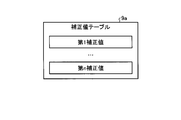
- the second storage unit 9 stores a correction value table 9a including first correction values,..., Nth correction values.
- FIG. 4 is a diagram illustrating a correction value table 9a stored in the second storage unit 9 in the air conditioner 1 according to the first embodiment.
- the first correction value corresponds to the first motor 2-1 and is a value for correcting the reference value
- the nth correction value corresponds to the nth motor 2-n and the reference value is set. This is a value for correction.
- the first correction value,..., The nth correction value is determined at the time of manufacturing the air conditioner 1 and stored in the second storage unit 9.
- the calculation unit 82 calculates, for each motor, a control constant for controlling the motor using the reference value stored in the first storage unit 81 and the correction value stored in the second storage unit 9. In the following, it is assumed that the calculation unit 82 calculates the control constant using the first phase angle reference value stored in the first storage unit 81. For example, the calculation unit 82 calculates the first control constant for controlling the first motor 2-1 by adding the first correction value stored in the second storage unit 9 to the first phase angle reference value. To do. Alternatively, for example, the calculation unit 82 calculates the first control constant by integrating the first phase angle reference value and the first correction value.
- the calculation unit 82 adds the nth correction value stored in the second storage unit 9 to the first phase angle reference value, thereby obtaining an nth control constant for controlling the nth motor 2-n. calculate.
- the calculation unit 82 calculates the nth control constant by integrating the first phase angle reference value and the nth correction value.
- the method for calculating the control constant performed by the calculation unit 82 is a method according to at least one of the motor type and the motor control method, and is not limited to the method described above. In any case, the calculation unit 82 calculates, for each motor, a control constant for controlling the motor using the reference value stored in the first storage unit 81 and the correction value stored in the second storage unit 9. .
- the microcomputer 8 further includes a control unit 83 that controls the first motor 2-1,..., The nth motor 2-n using the control constant calculated by the calculation unit 82.
- a specific example of the operation of the control unit 83 is as follows. For the first motor 2-1, the control unit 83 uses the first control constant calculated by the calculation unit 82 to send a control signal for turning on or off the first gate circuit 5-1 to the first gate circuit 5-1. And the first gate circuit 5-1 performs a switching process, and controls to apply a three-phase AC voltage to the first motor 2-1 using a DC voltage obtained by the DC power supply circuit 6.
- the control unit 83 uses the n-th control constant calculated by the calculation unit 82 to transmit a control signal for turning on or off the n-th gate circuit 5-n.
- 5-n is output to cause the n-th gate circuit 5-n to perform switching processing, and control is performed to apply a three-phase AC voltage to the n-th motor 2-n using the DC voltage obtained by the DC power supply circuit 6. .
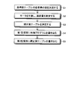
- FIG. 5 is a process diagram showing a part of the procedure of the method for manufacturing the air conditioner 1 of the first embodiment. Each step of the process diagram of FIG. 5 is performed by the manufacturer of the air conditioner 1.
- the manufacturer determines the value of each element in the reference value table 81a (S1).
- the first position detection circuit 3-1 is attached to the first motor 2-1, and detects the position of the shaft of the first motor 2-1.
- a position detection circuit for detecting the position of the motor shaft is attached to the motor.
- the angle of the position detection circuit with respect to the motor axis is predetermined by design, but in actual manufacturing, the angle differs for each motor. Since the angle is different for each motor, a control constant for each motor is required.
- the calculation unit 82 in the microcomputer 8 controls the motor using the reference value stored in the first storage unit 81 and the correction value stored in the second storage unit 9 for each motor.
- the control constant for calculating is calculated.
- a reference value is required for the calculation unit 82 to calculate the control constant.
- the manufacturer determines a reference value that is a reference control constant for controlling the reference motor. Specifically, in step S1, the manufacturer determines the first phase angle reference value, the second phase angle reference value, and the third phase angle reference value.
- the reference motor is a motor to which a position detection circuit is attached at an angle with an extremely small error from the designed angle, and is specified by the manufacturer.
- the manufacturer drives the reference motor while increasing or decreasing the control constant, measures the power consumption of the motor and the motor control circuit, and determines the control constant that minimizes the power consumption as the reference value.
- the manufacturer produces the first motor 2-1,..., The nth motor 2-n, and for the produced first motor 2-1,.
- the error amount is measured (S2).
- the error amount for the first motor 2-1 is attached to the angle of the first position detection circuit 3-1 attached to the first motor 2-1 with respect to the axis of the first motor 2-1 and the reference motor.
- This is a first correction value which is information of an amount for specifying a difference from the angle of the position detection circuit with respect to the reference motor axis.
- the error amount for the n-th motor 2-n includes the angle of the n-th position detection circuit 3-n attached to the n-th motor 2-n with respect to the axis of the n-th motor 2-n and the position attached to the reference motor.
- This is an nth correction value that is information of an amount for identifying a difference from an angle with respect to the reference motor axis of the detection circuit.
- the first correction value corresponds to the first motor 2-1 and is a value for correcting the reference value
- the nth correction value corresponds to the nth motor 2-n and the reference value is set. This is a value for correction.
- the manufacturer determines a correction value included in the correction value table 9a, thereby determining the correction value table 9a (S3).
- the correction values included in the correction value table 9a are the first correction value,..., The nth correction value measured in step S2.
- the manufacturer writes a program for controlling the air conditioner 1 in the first storage unit 81 of the microcomputer 8 using, for example, a personal computer (S4).
- the program includes the value of each element of the reference value table 81a determined in step S1. That is, in step S4, the first storage unit 81 stores a reference value that is a reference control constant for controlling the reference motor.
- the manufacturer writes the correction value table 9a including the correction value determined in step S3 in the second storage unit 9 using, for example, a personal computer (S5).
- the correction value table 9a includes first correction values,..., Nth correction values. That is, in step S5, the second storage unit 9 stores the first correction value,..., The nth correction value.
- the manufacturer may write other information in the second storage unit 9 together with the correction value table 9a.
- step S5 may be performed before the operation in step S4.
- step S1 may be performed before the operation of step S4, and the operations of step S2 and step S3 may be performed before the operation of step S5.
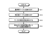
- FIG. 6 is a flowchart showing the operation of the air conditioner 1 of the first embodiment. For example, when a button for starting operation not shown in FIG. 1 is pressed by the user, or a button for supplying power to the air conditioner 1 not shown in FIG. 1 is pressed by the user. As a result, the air conditioner 1 starts operation. Both of the two buttons are attached to the casing of the air conditioner 1.
- the calculation unit 82 of the microcomputer 8 reads the reference value table 81a from the first storage unit 81 of the microcomputer 8 (S11). Next, the calculation unit 82 reads the correction value table 9a from the second storage unit 9 (S12). The operation in step S12 may be performed before the operation in step S11.
- the calculation unit 82 uses the reference value table 81a and the correction value table 9a to calculate a control constant for controlling the motor for each motor (S13). For example, the calculation unit 82 adds the first correction value in the correction value table 9a to the first phase angle reference value in the reference value table 81a, thereby controlling the first control constant for controlling the first motor 2-1. Is calculated. Alternatively, for example, the calculation unit 82 adds the nth correction value in the correction value table 9a to the nth phase angle reference value in the reference value table 81a, thereby controlling the nth motor 2-n. Calculate the control constant.
- the control unit 83 of the microcomputer 8 controls the first gate circuit 5-1,..., The nth gate circuit 5-n using the control constant calculated by the calculation unit 82, and thereby the first gate circuit 5-n.
- the first motor 2-1,..., The nth motor 2-n are controlled (S14).
- the control unit 83 outputs a control waveform corresponding to the first control constant to the first gate circuit 5-1 using the first control constant calculated by the calculation unit 82, and thereby the first motor 2- 1 operation is controlled.
- the control unit 83 outputs a control waveform corresponding to the nth control constant to the nth gate circuit 5-n using the nth control constant calculated by the calculation unit 82, and thereby the nth control constant. Controls the operation of the motor 2-n.
- the air conditioner 1 calculates the control constant for controlling the motor by using the reference value stored in the first storage unit 81 and the correction value stored in the second storage unit 9. Control the motor using control constants.
- a manufacturer develops a future air conditioner, if the development is performed based on the air conditioner 1, only the correction value stored in the second storage unit 9 may be changed instead of all the control constants. Therefore, future air conditioners can be developed more easily than before. That is, the air conditioner 1 can make future air conditioner development easier than before.
- the air conditioner 1 can respond to aged deterioration of a motor. That is, the air conditioner 1 can drive the motor based on an appropriate control constant even if the motor deteriorates over time. Since the motors are driven based on appropriate control constants, the power consumption when each motor is driven is close to the power consumption when the reference motor is driven and decreases.
- the air conditioner 1 since the 1st memory
- the first storage unit 81 is included in the microcomputer 8 and is generally called a main storage device. That is, the air conditioner 1 can be equipped with a microcomputer 8 having a main storage device having a relatively small storage capacity. In other words, the manufacturer can use the microcomputer 8 having the main storage device having a relatively small storage capacity when manufacturing the air conditioner 1. Furthermore, the air conditioner 1 makes it easy for the manufacturer to select the microcomputer 8 to be mounted.
- the first motor 2-1,..., The nth motor 2-n are three-phase AC motors whose rotation is controlled by a three-phase AC voltage.
- the first motor 2-1,..., The nth motor 2-n may be motors other than the three-phase AC motor.
- the types of the first motor 2-1,..., The nth motor 2-n are not limited.
- the calculation unit 82 and the control unit 83 in the air conditioner 1 are realized by the microcomputer 8, but some or all of the functions of the calculation unit 82 and the control unit 83 are processing circuits. 70 may be realized.
- FIG. 7 is a diagram illustrating that at least a part of the calculation unit 82 and the control unit 83 constituting the air conditioner 1 of the first embodiment is the processing circuit 70.
- the processing circuit 70 is dedicated hardware. That is, the processing circuit 70 is, for example, a single circuit, a composite circuit, a programmed processor, a parallel programmed processor, an ASIC (Application Specific Integrated Circuit), an FPGA (Field-Programmable Gate Array), or a combination thereof. It is a thing.
- the component having a part of the plurality of functions of the calculation unit 82 and the control unit 83 may be dedicated hardware separate from the component having the remaining function.
- the first storage unit 81 is included in the microcomputer 8, but the first storage unit 81 may be a storage device provided outside the microcomputer 8.
- the air conditioner of the second embodiment is an apparatus similar to the air conditioner 1 of the first embodiment, and includes a microcomputer 8A instead of the microcomputer 8 included in the air conditioner 1.
- the calculation unit 82 in the first embodiment is replaced with a calculation unit 82a
- the second storage unit 9 in the first embodiment is replaced with a second storage unit 9X.
- the second storage unit 9X is a non-volatile memory like the second storage unit 9 of the first embodiment.
- FIG. 8 is a diagram showing a configuration of the microcomputer 8A in the air conditioner of the second embodiment.
- the microcomputer 8A according to the second embodiment includes a first storage unit 81 and a control unit 83 included in the microcomputer 8 according to the first embodiment, and also includes a calculation unit 82a and a correction value calculation unit 84.
- the calculation unit 82a calculates the control constant of each motor, similarly to the calculation unit 82 of the first embodiment.
- the correction value calculator 84 is detected by the first position detection circuit 3-1, the nth position detection circuit 3-n, the first current detection circuit 4-1, the nth current detection circuit 4-n, and the voltage detection circuit 7. Based on the obtained value, a correction value for correcting the reference value of the first storage unit 81 is calculated.
- the reference value is a reference control constant for controlling the reference motor.
- the correction value calculation unit 84 calculates the correction value when the calculation unit 82a issues a request to calculate the correction value, and outputs the correction value obtained by the calculation to the calculation unit 82a.
- the second storage unit 9X stores a correction value table 9a including first correction values,..., Nth correction values, and a correction value calculation unit 84. Stores information for specifying whether or not the correction value needs to be calculated in the area of calculation necessity 9b.
- the calculation unit 82a includes information “correction required” indicating that the correction value calculation unit 84 needs to calculate a correction value in the area of calculation necessity 9b of the second storage unit 9X, and the correction value calculation unit 84 It is determined which of the information “correction unnecessary” indicating that the correction value does not need to be calculated is stored.
- the calculation unit 82a issues a request for calculating a correction value to the correction value calculation unit 84 to correct the correction value for each motor. Obtained from the value calculation unit 84.
- the calculation unit 82a calculates a control constant for controlling the motor using the reference value stored in the first storage unit 81 and the correction value obtained by the calculation by the correction value calculation unit 84.
- the calculation unit 82a changes the information on the necessity / unnecessary calculation 9b to the information “correction unnecessary”.
- the calculation unit 82a stores the first storage unit 81 for each motor as in the calculation unit 82 of the first embodiment.
- a control constant for controlling the motor is calculated using the reference value to be corrected and the correction value stored in the second storage unit 9X.
- the control unit 83 controls each motor as in the first embodiment.
- FIG. 9 is a flowchart showing a procedure of a method of manufacturing the second storage unit 9X in the air conditioner of the second embodiment.
- the manufacturer of the air conditioner of Embodiment 2 creates a substrate having the second storage unit 9X (S21).
- the manufacturer writes “correction required” information in the area of calculation necessity 9b of the second storage unit 9X (S22).
- FIG. 10 is a flowchart showing the operation procedure of the microcomputer 8A in the air conditioner of the second embodiment.
- the calculation unit 82a reads the reference value table 81a from the first storage unit 81 (S31).
- the calculation unit 82a reads the information in the calculation necessity / non-necessity 9b area of the second storage unit 9X (S32), and determines whether the information “correction required” is stored in the calculation necessity / non-necessity 9b area. (S33).
- the calculation unit 82a When the information “necessity of correction” is stored in the area of calculation necessity 9b (Yes in S33), the calculation unit 82a outputs the reference value included in the reference value table 81a read in step S31 to the control unit 83.
- the control unit 83 controls each gate circuit using the reference value included in the reference value table 81a (S34).
- the correction value calculator 84 is detected by the first position detection circuit 3-1, the nth position detection circuit 3-n, the first current detection circuit 4-1, the nth current detection circuit 4-n, and the voltage detection circuit 7. Based on each value, a correction value for correcting the reference value of the first storage unit 81 is calculated (S35). Details of the operation performed in step S35 will be described later with reference to FIG.
- the calculation unit 82a writes the correction value obtained by the correction value calculation unit 84 to the correction value table 9a of the second storage unit 9X (S36), and “correction is unnecessary” in the area of calculation necessity 9b in the second storage unit 9X. Is written (S37).
- the calculation unit 82a uses the correction value obtained by the correction value calculation unit 84 and the reference value table 81a read in step S31 so that the calculation unit 82 according to the first embodiment calculates the control constant. Every time, a control constant for controlling the motor is calculated (S39).
- the calculation unit 82a reads the correction value table 9a from the second storage unit 9X (S38), and similarly to the first embodiment, using the correction value table 9a and the reference value table 81a read in step S31, For each motor, a control constant for controlling the motor is calculated (S39). After step 39, the control unit 83 controls the first gate circuit 5-1,..., The nth gate circuit 5-n using the control constant calculated by the calculation unit 82a. 2-1,..., N-th motor 2-n is controlled (S40).
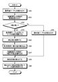
- FIG. 11 is a flowchart showing a procedure of operations performed by the microcomputer 8A in the air conditioner of Embodiment 2 in step S35 of the flowchart of FIG.
- the correction value calculator 84 calculates the power consumption of the first gate circuit 5-1 based on the values detected by the first current detection circuit 4-1 and the voltage detection circuit 7 (S41). Similarly, the correction value calculator 84 calculates the power consumption of the n-th gate circuit 5-n based on the values detected by the n-th current detection circuit 4-n and the voltage detection circuit 7 (S41). .
- the calculating unit 82a copies the control constant currently used for controlling the first gate circuit 5-1,..., The nth gate circuit 5-n and sets it as a reference value (S42).
- the calculation unit 82a calculates a control constant obtained by correcting the control constant, which is the reference value set in step S42, in the positive direction.
- the control unit 83 calculates the control constant calculated by the calculation unit 82a and sets the reference value in the positive direction.
- the first gate circuit 5-1,..., And the n-th gate circuit 5-n are controlled using the corrected control constant (S43).
- the calculation unit 82a increases the phase angle by 5 degrees and performs control when the phase angle is 35 degrees. Calculate a constant.
- times is an example, Comprising: The angle which increases a phase angle is not limited to 5 degree
- the correction value calculator 84 calculates the power consumption of the first gate circuit 5-1 based on the values detected by the first current detection circuit 4-1 and the voltage detection circuit 7 (S44). The correction value calculator 84 determines whether or not the power consumption calculated in step S44 is lower than the power consumption calculated in step S41 (S45). If the correction value calculation unit 84 determines that the power consumption calculated in step S44 is lower than the power consumption calculated in step S41 (Yes in S45), the operation of the microcomputer 8A proceeds to step S42. That is, in the case of Yes in step S45, the microcomputer 8A repeats each operation from step S41 to step S44.
- the calculation unit 82a includes the first gate circuit 5-1. ,..., A control constant currently used for controlling the n-th gate circuit 5-n is copied and set as a reference value (S46).
- the calculation unit 82a calculates a control constant obtained by correcting the control constant, which is the reference value set in step 46, in the negative direction.
- the control unit 83 calculates the control constant calculated by the calculation unit 82a and sets the reference value in the negative direction.
- the first gate circuit 5-1,..., The nth gate circuit 5-n are controlled using the corrected control constant (S47).
- the calculation unit 82a reduces the phase angle by 5 degrees and performs control when the phase angle is 25 degrees. Calculate a constant.
- times is an example, Comprising: The angle which reduces a phase angle is not limited to 5 degree
- the correction value calculator 84 calculates the power consumption of the first gate circuit 5-1 based on the values detected by the first current detection circuit 4-1 and the voltage detection circuit 7 (S48). The correction value calculator 84 determines whether or not the power consumption calculated in step S48 is lower than the power consumption calculated in step S44 (S49). When the correction value calculation unit 84 determines that the power consumption calculated in step S48 is lower than the power consumption calculated in step S44 (Yes in S49), the operation of the microcomputer 8A proceeds to step S46. That is, in the case of Yes in step S49, the microcomputer 8A repeats each operation from step S46 to step S48.
- the correction value calculation unit 84 uses the first storage unit 81.
- the difference between the reference value included in the reference value table 81a stored in the control value and the currently used control constant is determined as a correction value (S50).
- each motor Since the air conditioner of Embodiment 2 calculates the control constant in consideration of the power consumption in each gate circuit, each motor is changed without changing the information in the correction value table 9a stored in the second storage unit 9X.
- Each gate circuit can be controlled by dynamically calculating a control constant suitable for the above.
- the air conditioner of the second embodiment once the correction value is calculated based on the power consumption, it is not necessary to calculate the correction value thereafter, and the calculation load of the microcomputer 8A is suppressed. Can do. Since the calculation load of the microcomputer 8A is reduced, an inexpensive microcomputer that does not have high calculation capability can be used for the microcomputer 8A, and thus the air conditioner of Embodiment 2 can be manufactured at low cost.
- calculation unit 82a, the control unit 83, and the correction value calculation unit 84 in the air conditioner according to the second embodiment are realized by the microcomputer 8A, the calculation unit 82a, the control unit 83, and the correction value calculation unit 84 have a plurality of functions. Part or all may be realized by a processing circuit equivalent to the processing circuit 70 of FIG.
- the air conditioner of the third embodiment is an apparatus similar to the air conditioner of the second embodiment, and includes a microcomputer 8B instead of the microcomputer 8A included in the air conditioner.
- the second storage unit 9X of the second embodiment is replaced with a second storage unit 9Y.
- the second storage unit 9Y is a non-volatile memory like the second storage unit 9X of the second embodiment.
- differences from the second embodiment will be mainly described.
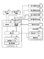
- FIG. 12 is a diagram showing a configuration of the microcomputer 8B in the air conditioner of the third embodiment.
- the microcomputer 8B according to the third embodiment includes all the components included in the microcomputer 8A according to the second embodiment, and includes a measuring unit 85.
- the measuring unit 85 measures the operation time of the first motor 2-1,..., The nth motor 2-n.
- the measuring unit 85 may measure the operation time of each of the plurality of motors, or may measure the operation time of any one of the plurality of motors.
- the second storage unit 9Y stores a correction value table 9a including first correction values,..., Nth correction values, and a correction value calculation unit 84. Stores information specifying whether or not the correction value needs to be calculated in the area of calculation necessity 9b.
- the second storage unit 9Y stores the cumulative operation time of the first motor 2-1,..., The nth motor 2-n in the region of the cumulative operation time 9c.
- the measuring unit 85 of the microcomputer 8B writes the measured time during which the first motor 2-1,..., N-th motor 2-n operates in the area of the cumulative operation time 9c. For example, the measurement unit 85 adds the measured operation time to the area of the accumulated operation time 9c for each motor.
- the measuring unit 85 determines whether or not the cumulative operation time stored in the area of the cumulative operation time 9c of the second storage unit 9Y has reached a predetermined threshold value, and the cumulative operation time has reached the threshold value. Is determined, the information “correction required” is written in the area of calculation necessity 9b of the second storage unit 9Y.
- There are a plurality of threshold values and the measuring unit 85 writes information “necessary for correction” in the area of calculation necessity 9b of the second storage unit 9Y every time the cumulative operation time reaches each threshold value.
- the plurality of threshold values are, for example, times that are integral multiples of 1000 hours. Specifically, examples of the plurality of threshold values are 1000 hours, 2000 hours, 3000 hours, 4000 hours, and 5000 hours.
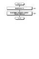
- FIG. 13 is a flowchart showing an operation procedure of the measurement unit 85 of the microcomputer 8B in the air conditioner of the third embodiment.
- the measurement unit 85 measures the operation time of the first motor 2-1,..., The nth motor 2-n (S51), and for each motor, The measured operation time of the motor is written in the area of the accumulated operation time 9c in the second storage unit 9Y (S52).
- the measuring unit 85 determines whether or not the cumulative operation time of each motor stored in the area of the cumulative operation time 9c of the second storage unit 9Y has reached the threshold (S53). When the measurement unit 85 determines that the accumulated operation time has not reached the threshold (No in S53), the measurement unit 85 performs the operation of Step S51 after the operation of Step S53. On the other hand, when the measurement unit 85 determines that the accumulated operation time has reached the threshold value (Yes in S53), the measurement unit 85 writes the information “correction required” in the area of calculation necessity 9b of the second storage unit 9Y (S54).
- the calculation unit 82a uses the correction value obtained by the correction value calculation unit 84 and the reference value table 81a as in the second embodiment. And a control constant for controlling the motor is calculated for each motor. That is, when the cumulative value of the motor operating time measured by the measuring unit 85 reaches a predetermined threshold value, the calculating unit 82a, the correction value obtained by the correction value calculating unit 84 by calculation, the reference value table 81a, For each motor, a control constant for controlling the motor is calculated.
- the air conditioner of Embodiment 3 updates the control constant when the cumulative operation time of the motor exceeds the threshold value. Since the control constant is updated, the motor can be controlled with an appropriate control constant even if the characteristics of the motor change due to deterioration over time. Furthermore, since the control constant is updated every time the cumulative operation time of the motor exceeds the threshold value, in other words, it is periodically updated, so even if the motor characteristics change due to aging, the appropriate control constant is set. The motor can be controlled originally. That is, the air conditioner of Embodiment 3 can suppress an increase in power consumption due to a change in motor characteristics when used for a long time.
- the calculation unit 82a, the control unit 83, the correction value calculation unit 84, and the measurement unit 85 in the air conditioner of Embodiment 3 are realized by the microcomputer 8B, the calculation unit 82a, the control unit 83, the correction value calculation unit 84, and Some or all of the plurality of functions of the measurement unit 85 may be realized by a processing circuit equivalent to the processing circuit 70 of FIG.
- the configuration described in the above embodiment shows an example of the contents of the present invention, and can be combined with another known technique, and can be combined with other configurations without departing from the gist of the present invention. It is also possible to omit or change the part.
- SYMBOLS 1 Air conditioner 2-1 1st motor, 2-n nth motor, 3-1, 1st position detection circuit, 3-n nth position detection circuit, 4-1, 1st current detection circuit, 4-n 1st n current detection circuit, 5-1 first gate circuit, 5-n nth gate circuit, 6 DC power supply circuit, 7 voltage detection circuit, 8, 8A, 8B microcomputer, 9, 9X, 9Y second storage unit, 9a Correction value table, 70 processing circuit, 81 first storage unit, 81a reference value table, 82, 82a calculation unit, 83 control unit, 84 correction value calculation unit, 85 measurement unit.
Landscapes
- Engineering & Computer Science (AREA)
- Chemical & Material Sciences (AREA)
- Combustion & Propulsion (AREA)
- Mechanical Engineering (AREA)
- General Engineering & Computer Science (AREA)
- Physics & Mathematics (AREA)
- Fluid Mechanics (AREA)
- Air Conditioning Control Device (AREA)
- Control Of Multiple Motors (AREA)
Abstract
L'invention concerne un climatiseur comprenant : un moteur; une première unité de mémoire (81) destinée à stocker une valeur de référence; une unité de calcul (82) destinée à calculer une constante de commande servant à commander le moteur à l'aide de la valeur de référence stockée dans l'unité de mémoire (81) et une valeur de correction correspondant au moteur et servant à corriger la valeur de référence; et une unité de commande (83) destinée à commander le moteur à l'aide de la constante de commande calculée par l'unité de calcul (82).
Priority Applications (2)
| Application Number | Priority Date | Filing Date | Title |
|---|---|---|---|
| JP2018518005A JP6667625B2 (ja) | 2016-05-18 | 2016-05-18 | 空気調和機 |
| PCT/JP2016/064754 WO2017199376A1 (fr) | 2016-05-18 | 2016-05-18 | Climatiseur |
Applications Claiming Priority (1)
| Application Number | Priority Date | Filing Date | Title |
|---|---|---|---|
| PCT/JP2016/064754 WO2017199376A1 (fr) | 2016-05-18 | 2016-05-18 | Climatiseur |
Publications (1)
| Publication Number | Publication Date |
|---|---|
| WO2017199376A1 true WO2017199376A1 (fr) | 2017-11-23 |
Family
ID=60325200
Family Applications (1)
| Application Number | Title | Priority Date | Filing Date |
|---|---|---|---|
| PCT/JP2016/064754 Ceased WO2017199376A1 (fr) | 2016-05-18 | 2016-05-18 | Climatiseur |
Country Status (2)
| Country | Link |
|---|---|
| JP (1) | JP6667625B2 (fr) |
| WO (1) | WO2017199376A1 (fr) |
Citations (6)
| Publication number | Priority date | Publication date | Assignee | Title |
|---|---|---|---|---|
| JPH0538175A (ja) * | 1991-07-25 | 1993-02-12 | Hitachi Ltd | モータ制御装置 |
| JP2004187460A (ja) * | 2002-12-06 | 2004-07-02 | Mitsubishi Heavy Ind Ltd | インバータ制御装置、誘導電動機の制御装置及び誘導電動機システム |
| JP2008154313A (ja) * | 2006-12-14 | 2008-07-03 | Samsung Electronics Co Ltd | 電動モータの制御装置及びこれを備える洗濯機 |
| JP2009136085A (ja) * | 2007-11-30 | 2009-06-18 | Hitachi Ltd | 交流モータの制御装置 |
| JP2014128147A (ja) * | 2012-12-27 | 2014-07-07 | Daikin Ind Ltd | モータ制御装置 |
| WO2015129207A1 (fr) * | 2014-02-25 | 2015-09-03 | パナソニックIpマネジメント株式会社 | Procédé de réglage de paramètre de commande utilisé dans un dispositif de commande de moteur électrique, et dispositif de commande de moteur électrique utilisant ledit procédé de réglage de paramètre de commande |
Family Cites Families (3)
| Publication number | Priority date | Publication date | Assignee | Title |
|---|---|---|---|---|
| JP5116620B2 (ja) * | 2008-09-11 | 2013-01-09 | 三菱電機株式会社 | 電動機の駆動装置並びに冷凍空調装置 |
| JP5743133B2 (ja) * | 2010-10-05 | 2015-07-01 | 株式会社ジェイテクト | 電動パワーステアリング装置 |
| WO2013108356A1 (fr) * | 2012-01-16 | 2013-07-25 | 三菱電機株式会社 | Organe de commande de moteur |
-
2016
- 2016-05-18 WO PCT/JP2016/064754 patent/WO2017199376A1/fr not_active Ceased
- 2016-05-18 JP JP2018518005A patent/JP6667625B2/ja active Active
Patent Citations (6)
| Publication number | Priority date | Publication date | Assignee | Title |
|---|---|---|---|---|
| JPH0538175A (ja) * | 1991-07-25 | 1993-02-12 | Hitachi Ltd | モータ制御装置 |
| JP2004187460A (ja) * | 2002-12-06 | 2004-07-02 | Mitsubishi Heavy Ind Ltd | インバータ制御装置、誘導電動機の制御装置及び誘導電動機システム |
| JP2008154313A (ja) * | 2006-12-14 | 2008-07-03 | Samsung Electronics Co Ltd | 電動モータの制御装置及びこれを備える洗濯機 |
| JP2009136085A (ja) * | 2007-11-30 | 2009-06-18 | Hitachi Ltd | 交流モータの制御装置 |
| JP2014128147A (ja) * | 2012-12-27 | 2014-07-07 | Daikin Ind Ltd | モータ制御装置 |
| WO2015129207A1 (fr) * | 2014-02-25 | 2015-09-03 | パナソニックIpマネジメント株式会社 | Procédé de réglage de paramètre de commande utilisé dans un dispositif de commande de moteur électrique, et dispositif de commande de moteur électrique utilisant ledit procédé de réglage de paramètre de commande |
Also Published As
| Publication number | Publication date |
|---|---|
| JP6667625B2 (ja) | 2020-03-18 |
| JPWO2017199376A1 (ja) | 2018-08-30 |
Similar Documents
| Publication | Publication Date | Title |
|---|---|---|
| CN104729017B (zh) | 空调器的恒风量控制方法、控制装置 | |
| JP2008278573A (ja) | インバータ装置及びそれに用いられる半導体装置。 | |
| CN104753409A (zh) | 风扇电机的驱动控制装置 | |
| JP6841336B2 (ja) | モータの制御装置及び記憶媒体 | |
| CN104702187B (zh) | 电机转子位置的估算方法 | |
| CN113566394A (zh) | 一种温度检测的方法、装置、设备及存储介质 | |
| JP2016019374A (ja) | 制御装置、画像形成装置、制御方法及びプログラム | |
| US11081985B2 (en) | Synchronous rotating machine control device and machine learning device | |
| JP7290434B2 (ja) | モータ駆動制御装置及びモータの駆動制御方法 | |
| JP6667625B2 (ja) | 空気調和機 | |
| JP6890056B2 (ja) | 温度検出装置及び誤差補正方法 | |
| JP4422967B2 (ja) | 電動機の運転制御装置 | |
| KR20160068478A (ko) | 화상형성장치 및 화상형성장치의 동작 방법 | |
| JP6740937B2 (ja) | モータ制御装置のインテリジェントパワーモジュール | |
| CN105099326A (zh) | 变频器参数优化 | |
| US12375015B2 (en) | Drive system and control method | |
| CN1972112A (zh) | 马达的控制装置以及方法 | |
| JPWO2019073633A1 (ja) | 速度算出装置および電力変換装置 | |
| JP2009225545A (ja) | ブラシレスモータ制御装置、ブラシレスモータ、及びブラシレスモータ制御装置の設定方法 | |
| JP5582442B2 (ja) | モータ駆動制御装置、モータ駆動制御方法及びこれを利用したモータ | |
| JP7080403B2 (ja) | インバータ装置、空気調和機およびインバータ装置の制御方法 | |
| JP2020205716A (ja) | モータ制御装置およびオフセット量算出方法 | |
| JP6393246B2 (ja) | モータ駆動制御装置及びモータ駆動制御装置の制御方法 | |
| JP5510406B2 (ja) | ブラシレスdcモータの制御装置およびそれを用いた送風装置 | |
| JP2004187464A (ja) | 電動機制御装置 |
Legal Events
| Date | Code | Title | Description |
|---|---|---|---|
| ENP | Entry into the national phase |
Ref document number: 2018518005 Country of ref document: JP Kind code of ref document: A |
|
| NENP | Non-entry into the national phase |
Ref country code: DE |
|
| 121 | Ep: the epo has been informed by wipo that ep was designated in this application |
Ref document number: 16902395 Country of ref document: EP Kind code of ref document: A1 |
|
| 122 | Ep: pct application non-entry in european phase |
Ref document number: 16902395 Country of ref document: EP Kind code of ref document: A1 |