WO2017199377A1 - Lit démontable - Google Patents
Lit démontable Download PDFInfo
- Publication number
- WO2017199377A1 WO2017199377A1 PCT/JP2016/064765 JP2016064765W WO2017199377A1 WO 2017199377 A1 WO2017199377 A1 WO 2017199377A1 JP 2016064765 W JP2016064765 W JP 2016064765W WO 2017199377 A1 WO2017199377 A1 WO 2017199377A1
- Authority
- WO
- WIPO (PCT)
- Prior art keywords
- frame
- frame body
- enclosure
- members
- surrounding
- Prior art date
- Legal status (The legal status is an assumption and is not a legal conclusion. Google has not performed a legal analysis and makes no representation as to the accuracy of the status listed.)
- Ceased
Links
Images


Classifications
-
- A—HUMAN NECESSITIES
- A47—FURNITURE; DOMESTIC ARTICLES OR APPLIANCES; COFFEE MILLS; SPICE MILLS; SUCTION CLEANERS IN GENERAL
- A47C—CHAIRS; SOFAS; BEDS
- A47C19/00—Bedsteads
-
- A—HUMAN NECESSITIES
- A47—FURNITURE; DOMESTIC ARTICLES OR APPLIANCES; COFFEE MILLS; SPICE MILLS; SUCTION CLEANERS IN GENERAL
- A47D—FURNITURE SPECIALLY ADAPTED FOR CHILDREN
- A47D11/00—Children's furniture convertible into other kinds of furniture, e.g. children's chairs or benches convertible into beds or constructional play-furniture
-
- A—HUMAN NECESSITIES
- A47—FURNITURE; DOMESTIC ARTICLES OR APPLIANCES; COFFEE MILLS; SPICE MILLS; SUCTION CLEANERS IN GENERAL
- A47D—FURNITURE SPECIALLY ADAPTED FOR CHILDREN
- A47D7/00—Children's beds
Definitions
- the present invention relates to an assembly-type bed that can be easily rearranged by a user.
- the present invention includes an enclosure having an upper enclosure and a lower enclosure, and the upper enclosure and the lower enclosure are vertically separated at an intermediate portion of the enclosure.
- the upper frame body and the lower frame body each have side frame members on both side surfaces in the longitudinal direction, and these side frame members are vertically disposed between the upper handrail member, the lower handrail member, and each handrail member.
- a plurality of balustrades extending in a vertical direction, and when the upper frame body and the lower frame body are coupled, the plurality of balustrades extend in a straight line, and a floor plate is provided at an intermediate portion of the frame. It is characterized by.
- each of the upper frame body and the lower frame body includes wife frame members on both side surfaces in a lateral direction, and the upper frame body and the lower frame body are separated, and the wife It is characterized in that each of the upper frame body and the lower frame body can be used as a storage shelf by standing upright with a frame member as a bottom.
- the floor board is fixed to the bottom of the upper surrounding frame, and a frame material is exposed on the back surface.
- the lower handrail member of the upper surrounding body and the upper handrail member of the lower surrounding body are in close contact, and a dowel hole is provided in one of the handrail members, and the other handrail A dowel that fits in the dowel hole is disposed on the member.
- one of the side surface frame members and one of the end frame members is a connecting member that can be changed between a closed state in which the side frame members are overlapped and folded and an open state that is arranged to form a substantially L shape. It is connected by.
- an assembling-type bed that can be used in the form of a bed having a floor plate in the middle part of the surrounding frame is separated vertically into an upper surrounding frame body and a lower surrounding frame body. Thus, it can be easily used in another form.
- FIG. 1 is a perspective view showing a form of a crib of an assembly-type bed according to an embodiment of the present invention.
- FIG. 2 is a perspective view showing a state in which the crib body is vertically divided into two.
- FIG. 3 is a perspective view showing a storage shelf which is an example of a form obtained by rearranging the assembly-type bed.
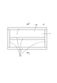
- FIG. 4 is a bottom view of the floor board.
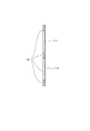
- FIG. 5 is a cross-sectional view taken along the line II of FIG.
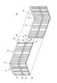
- FIG. 6 is an exploded perspective view of the assembled bed.
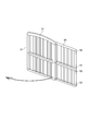
- FIG. 7 is a perspective view showing a state in which the wife frame member and the front frame or the rear frame are folded.
- FIG. 1 is a perspective view showing a form of a crib 2 of the assembly-type bed 1 according to the present embodiment.
- the assemblable bed 1 is configured to be rearranged from a baby bed 2 to another form such as a storage shelf 3 as the child grows or as necessary.
- the crib 2 includes a crib body 10 having a surrounding frame 20 formed in a rectangular enclosure shape.
- the crib body 10 is provided with a floor board 11 attached to the inner side of the surrounding frame 20 at a predetermined height position from the installation surface substantially horizontally.
- the baby bed 2 is configured so that a futon or a mat can be placed on the floor board 11 and used as a baby bed. That is, the crib 2 has a structure that satisfies the standards related to cribs such as JIS standards and ISO standards.
- the crib 2 is configured such that the height from the upper end surface 11A of the floor board 11 to the upper end of the surrounding frame 20 is 600 mm or more, and the height from the floor surface to the upper end face 11A of the floor board 11 is 500 mm or less. It is configured.
- the surrounding frame 20 connects a pair of end frame members 21 and 22 constituting both side surfaces in the short direction and a pair of side surface frame members 23 and 24 constituting both side surfaces in the longitudinal direction in a rectangular frame shape in plan view. Is configured.
- the end frame members 21 and 22 are divided into upper end frame members 21A and 22A and lower end frame members 21B and 22B.
- the side frame members 23 and 24 are divided into upper side frame members 23A and 24A and lower side surfaces.
- the frame members 23B and 24B can be divided.
- the upper end frame members 21A and 22A and the upper side frame members 23A and 24A have the same height
- the lower end frame members 21B and 22B and the lower side frame members 23B and 24B have the same height. have.
- Each of the end frame members 21A, 22A, 21B, and 22B and each of the side surface frame members 23A, 24A, 23B, and 24B are a pair of column members 31 that extend vertically and an upper frame that is an upper and lower beam member extending horizontally.
- 25A, 25B, 27A, 27B (upper handrail member) and lower rails 26A, 26B, 28A, 28B (lower handrail member) are formed in a frame shape having four sides.
- the surrounding frame 20 includes an upper surrounding frame body 20A in which the upper end frame members 21A and 22A and the upper side surface frame members 23A and 24A are connected in a rectangular frame shape in plan view, a lower end frame member 21B and 22B, and a lower side frame member It is configured to be vertically divided into an upper surrounding frame body 20A in which 23B and 24B are connected in a rectangular frame shape in plan view.
- the floor board 11 is fixed to the upper surrounding frame 20A. More specifically, the floor plate 11 is fixed to the lower rail 26A of the upper end frame members 21A and 22A and the lower rail 28A of the upper side surface frame members 23A and 24A.
- the floor board 11 is installed such that the upper end surface 11A is flush with the upper ends of the lower rails 26A, 28A. That is, the floor plate 11 is provided in a divided portion 5 (intermediate portion) of the upper surrounding frame body 20A and the upper surrounding frame body 20A. It is configured to be in a fixed state.
- a reinforcing member 33 for improving the rigidity of the lower surrounding frame 20B is provided on the frame-shaped bottom 20C formed by the lower rail 26B and the lower rail 28B of the lower surrounding frame 20B.
- the reinforcing member 33 includes a reinforcing member 33A provided on the inner side of the lower surrounding frame body 20B along the lower rail 26B, and a reinforcing member 33B provided on the inner side of the lower surrounding frame member 20B along the lower rail 28B. Composed. Thereby, the reinforcing member 33 is provided in a frame shape on the bottom 20C of the lower surrounding frame 20B.
- the upper surrounding body 20A is set higher than the height H2 of the lower surrounding frame 20B.
- the height H2 of the lower enclosure 20B is set to an appropriate height at which the upper end surface 11A of the floor board 11 is not disposed at a position higher than 500 mm from the floor when the casters 32 are attached to the bottom 20C of the lower enclosure 20B. Is configured.
- the casters 32 are provided at the four corners of the bottom surface of the bottom 20C, respectively, so that the crib 2 can be easily moved.
- the upper end frame members 21A and 22A are provided with handrails 29A that are connected to each other between the upper beam 25A and the lower beam 26A and extend vertically at predetermined intervals.
- the upper side frame members 23A and 24A are provided with handrails 30A that connect the upper rail 27A and the lower rail 28A and extend vertically at a predetermined interval.
- the lower end frame members 21B and 22B are provided with handrails 29B that are connected to each other between the upper rail 25B and the lower rail 26B and extend vertically at a predetermined interval.
- the lower side surface frame members 23B and 24B are provided with handrails 30B that are connected to each other between the upper rail 27B and the lower rail 28B and extend vertically at predetermined intervals.
- the handrails 29A, 29B, 30A, 30B are set so that the distance between the handrails adjacent to each other or between the handrails 29A, 29B, 30A, 30B and the column members 31 at the four corners of the surrounding frame 20 is 85 mm or less. Is provided.
- the handrails 29A and 30A of the upper surrounding body 20A and the handrails 29B and 30B of the lower surrounding body 20B are respectively a vertical color line when the upper surrounding body 20A and the lower surrounding body 20B are joined. It is configured to line up.
- the surrounding frame 20 is configured such that the lower rail 28A of the upper surrounding frame 20A and the upper rail 27B of the lower surrounding frame 20B are in close contact with each other.
- dowel holes are formed in advance at positions corresponding to the lower rail 28A and the upper rail 27B. Then, the upper frame body 20A and the lower frame body 20B can be obtained by fitting the dowels fitted into one of the dowel holes of the upper frame body 20A and the lower frame body 20B into the other dowel holes. Can be positioned and coupled.
- FIG. 2 is a diagram illustrating a state in which the surrounding frame 20 is vertically divided into an upper surrounding frame body 20A and a lower surrounding frame body 20B.
- the surrounding frame 20 is divided into an upper surrounding frame body 20A and a lower surrounding frame body 20B in the vertical direction, and the surrounding frame bodies 20A and 20B are separated from the end frame members 22A and 22B or the end frame. Any one of the members 21A and 21B can be used standing up.
- each frame body 20A, 20B can be used as the storage cases 40A and 40B.
- the end frame members 21A and 22A and the end frame members 21B and 22B are formed symmetrically, so that either of them can be used at the bottom.
- the construction may be such that the plate members 34A and 34B and the plate members 35A and 35B are mounted and used on the wife frame members 21A and 21B and the wife frame members 22A and 22B, respectively.
- the assembly-type bed 1 is configured to be easily deformable into the storage cases 40A and 40B by dividing the crib 2 into upper and lower parts.
- the end frame members 21A and 21B and the end frame members 22A and 22B are not limited to the configuration in which the handrails 29A and 29B are provided between the upper rails 25A and 25B and the lower rails 26A and 26B.
- plate material 35A, 35B may be sufficient.
- FIG. 3 is a view showing an example in which the assembly-type bed 1 is reconfigured into a form different from that of the baby bed 2.
- the assembly-type bed 1 is reassembled into the storage shelf 3.
- the side frame members 23 and 24 are formed symmetrically, the opposed handrails 30A and 30A and the handrails 30B and 30B are provided in a horizontal position. Thereby, it is possible to bridge the shelves 101, 102 between the handrails 30A, 30A or the handrails 30B, 30B facing each other, to bridge a hanger pipe (not shown), or to install the drawer 104. Can be easily transformed into a storage shelf or a hanger rack.
- the storage case 40A installed with a gap between them. , 40B may be connected by a shelf plate 103, and a shelf may be provided between the storage cases 40A, 40B.
- the parts such as the shelf boards 101, 102, and 103 and the drawer 104 are optional parts, and can be configured to be selectable according to a form desired by the user.
- FIG. 4 is a view showing the floor board 11 from the back surface 11B side.
- FIG. 5 is a cross-sectional view taken along the line II of FIG.
- the back surface 11B of the floor board 11 is a surface opposite to the front surface forming the upper end surface 11A of the floor board 11 on which the futon and the mat are placed when the assembling bed 1 is used as the crib 2.
- the floor plate 11 is a member that functions as a back plate of the storage case 40A when the assembly-type bed 1 is used as the storage cases 40A and 40B.
- a storage shelf such as the storage case 40A is generally used by being installed with the back surface 11B facing the wall surface of the living room, and is used by being fixed to the wall surface with a fixing tool such as a bolt in order to prevent toppling.
- a fixing tool such as a bolt
- the floor board 11 includes a plate material 111 having a rectangular shape in plan view having a size corresponding to the inner size of the crib 2, and a frame material 112 fixed to the back surface of the plate material 111. Consists of As the frame material 112, a so-called square material having a rectangular cross section can be suitably used.
- the frame material 112 functions as a reinforcing material for the floor board 11 and is provided along the four sides of the board material 111. Or / and provided across the short direction.
- the frame material 112 is attached to the back surface 11B of the floor plate 11 in an exposed state, when fixing the floor plate 11 to the wall surface, a bolt or a nail is driven into the frame material 12 to Can be fixed to.
- the storage case 40A can be stably fixed to the wall surface.
- the reinforcing members 33A and 33B are provided on the back side of the storage case 40B, the storage case 40B is fixed to the wall surface by fixing the reinforcing materials 33A and 33B to the wall surface. It can be fixed stably.
- the assembly-type bed 1 is furniture in a form (so-called flat pack) that is disassembled and packed into several parts and assembled by the user after opening.
- FIG. 6 is a view showing the surrounding frame 20 before assembly
- FIG. 7 is a view showing a connection state between any one of the end frame members 21 and 22 and any one of the side surface frame members 23 and 24. is there.
- the assembly-type bed 1 includes either one of the end frame members 21 and 22 and one of the side surface frame members 23 and 24 connected in a substantially L shape. Any one of 22 and any one of the side surface frame members 23 and 24 are comprised so that decomposition
- FIG. 6 is a diagram illustrating a state in which the end frame member 21 and the side frame member 24 are connected, and the end frame member 22 and the side frame member 23 are connected.
- the connecting portion 51 between the end frame member 21 and the side frame member 24 includes a state in which the end frame member 21 and the side frame member 24 shown in FIG. 6 are opened in a substantially L shape, and the end frame shown in FIG.
- the member 21 and the side frame member 24 are connected to each other in a closed state in which the member 21 and the side frame member 24 are folded and folded.
- the connecting portion 52 between the end frame member 22 and the side surface frame member 23 is connected so that the end frame member 22 and the side surface frame member 23 can be opened and closed in the same manner as the connecting portion 52.
- a hinge is attached to the connecting portions 51 and 52, and the wife frame member 21 and the side frame member 24 are connected to the wife frame member 22 and the side frame member 23 using the hinge.
- the end frame member 21 and the side frame member 24 that are connected and folded in advance, and the end frame member 22 and the side frame member 23 are approximately L. Open in a letter shape.
- the end frame member 21, the side frame member 24, the end frame member 22, and the side frame member 23 are opened in a substantially L shape in a connected state, they are self-supporting on the floor surface.
- the connection work with the member 21, the side frame member 24, the end frame member 22, and the side frame member 23 can be easily performed, and the surrounding frame 20 can be easily assembled.
- Positioning of the end frame member 21 and the side surface frame member 23 at the end of the end frame member 21 and the side surface frame member 24 and the connecting portion 51 and 52 of the end frame member 22 and the side surface frame member 23 are different.
- a boss hole 55 for positioning the end frame member 22 and the side frame member 24 is formed, and a boss 56 is fitted between the boss holes.
- the end frame member 21 and the side frame member 24, and the end frame member 22 and the side frame member 23, which are respectively connected in a substantially L shape can be easily positioned and connected using the bosses 56. it can.
- the enclosure 20 having the upper enclosure 20A and the lower enclosure 20B is provided, and the upper enclosure 20A and the lower enclosure 20B are enclosed by the enclosure.
- the upper enclosure 20A and the lower enclosure 20B are respectively provided with side frame members 23A, 24A, 23B, 24B on both side surfaces in the longitudinal direction, and these side frame members 23A.
- 24A, 23B, 24B are vertically connected to the upper rails 27A, 27B, which are upper handrail members, the lower rails 28A, 28B, which are lower handrail members, between the handrail members 27A, 28A, and between the handrail members 27B, 28B.
- balustrades 30A, 30B extending in a straight line, and when the upper enclosure 20A and the lower enclosure 20B are joined together, the balustrades 30A, 30B extend in a straight line, With a floor plate 11 to the intermediate portion of 0, characterized in that.
- the surrounding frame 20 is separated into an upper surrounding frame body 20A and a lower surrounding frame body 20B, and each of the surrounding frame bodies 20A and 20B is placed on, for example, the side rails 30A and 30B facing each other.
- the assembling bed 1 can be easily changed to a storage shelf.
- the assembly-type bed 1 can be transformed into a storage shelf with a simple configuration in which the surrounding frame 20 is vertically separated from the form of the baby bed 2, and even when the baby bed is no longer necessary, Can be used for a long time as a storage shelf.
- the upper frame body 20A and the lower frame body 20B are respectively provided with wife frame members 21A, 21B, 22A, 22B on both side surfaces in the short direction, and the upper frame body 20A and the lower frame body 20B.
- the upper frame body 20A and the lower frame body 20B can be used as storage shelves, respectively.
- the upper frame body 20A and the lower frame body 20B are erected with the longitudinal direction set to the vertical direction, and shelves and hanger pipes are bridged between the handrails 30A and 30B on the opposite side surfaces.
- the assembly-type bed 1 can be easily changed into the form of the storage shelves 3 of arbitrary shapes. Therefore, even when the baby bed is no longer needed, the assembling bed 1 can be easily reassembled into a storage shelf of any shape and used for a long time.
- the floor plate 11 is fixed to the bottom of the upper surrounding frame 20A, and the frame material 112 is exposed on the back surface 11B.
- the frame material 112 is attached to the back surface 11B of the floor board 11 in an exposed state. It can be driven and fixed to the wall stably.
- the lower handrail member 28A of the upper surrounding frame 20A and the upper handrail member 27B of the lower surrounding body 20B are in close contact with each other, a dowel hole is provided in one handrail member, and the other handrail member has A dowel that fits into the dowel hole is arranged.
- the upper enclosure 20A and the lower enclosure 20B can be easily positioned and connected using the dowels that fit into the dowel holes.
- the assembly-type bed in the form of the storage shelf 3 can be used. 1 can be easily rearranged into the form of a crib 2 and used.
- one side frame members 23 and 24 and the one end frame members 21 and 22 are changed into the closed state which overlapped and folded, and the open state arrange
Landscapes
- Invalid Beds And Related Equipment (AREA)
Abstract
La présente invention concerne un lit démontable qui peut être utilisé en tant que lit et peut être facilement réassemblé pour être utilisé dans une configuration différente. Le lit démontable comprend un châssis d'encadrement (20) qui possède un corps d'encadrement supérieur (20A) et un corps d'encadrement inférieur (20B). Le corps d'encadrement supérieur et le corps d'encadrement inférieur sont formés de manière à être verticalement séparables l'un de l'autre au niveau de la section intermédiaire du châssis d'encadrement. Une pluralité d'éléments formant rail de main (30A6, 30B) s'étendent verticalement de manière rectiligne lorsque le corps d'encadrement supérieur et le corps d'encadrement inférieur sont joints, et une plaque de plancher (11) est prévue au niveau de la section intermédiaire du châssis d'encadrement.
Priority Applications (2)
| Application Number | Priority Date | Filing Date | Title |
|---|---|---|---|
| JP2016549811A JPWO2017199377A1 (ja) | 2016-05-18 | 2016-05-18 | 組み立て式ベッド |
| PCT/JP2016/064765 WO2017199377A1 (fr) | 2016-05-18 | 2016-05-18 | Lit démontable |
Applications Claiming Priority (1)
| Application Number | Priority Date | Filing Date | Title |
|---|---|---|---|
| PCT/JP2016/064765 WO2017199377A1 (fr) | 2016-05-18 | 2016-05-18 | Lit démontable |
Publications (1)
| Publication Number | Publication Date |
|---|---|
| WO2017199377A1 true WO2017199377A1 (fr) | 2017-11-23 |
Family
ID=60325067
Family Applications (1)
| Application Number | Title | Priority Date | Filing Date |
|---|---|---|---|
| PCT/JP2016/064765 Ceased WO2017199377A1 (fr) | 2016-05-18 | 2016-05-18 | Lit démontable |
Country Status (2)
| Country | Link |
|---|---|
| JP (1) | JPWO2017199377A1 (fr) |
| WO (1) | WO2017199377A1 (fr) |
Cited By (1)
| Publication number | Priority date | Publication date | Assignee | Title |
|---|---|---|---|---|
| KR20220106529A (ko) * | 2021-01-22 | 2022-07-29 | 이강일 | 정리함으로 변형되는 베이비룸 |
Citations (8)
| Publication number | Priority date | Publication date | Assignee | Title |
|---|---|---|---|---|
| JPS253376Y1 (fr) * | 1948-11-08 | 1950-05-22 | ||
| JPS3926608Y1 (fr) * | 1962-06-22 | 1964-09-10 | ||
| JPS4156Y1 (fr) * | 1963-04-15 | 1966-01-05 | ||
| JPS5055449A (fr) * | 1973-09-18 | 1975-05-15 | ||
| JPS59111570U (ja) * | 1983-01-18 | 1984-07-27 | 清水 義教 | 本立てに組替できるベビ−ベツト |
| JPH07308244A (ja) * | 1994-05-18 | 1995-11-28 | Kintaroo:Kk | ラック兼用ベビーベッド |
| US6817046B1 (en) * | 2003-06-16 | 2004-11-16 | Mark Srour | One hand folding crib |
| JP3165522U (ja) * | 2010-11-06 | 2011-01-27 | ▲い▼倫 柯 | 板体構造 |
Family Cites Families (1)
| Publication number | Priority date | Publication date | Assignee | Title |
|---|---|---|---|---|
| JPS59188307U (ja) * | 1983-05-31 | 1984-12-13 | パネフリ工業株式会社 | 板材接続用コ−ナ−接手 |
-
2016
- 2016-05-18 JP JP2016549811A patent/JPWO2017199377A1/ja active Pending
- 2016-05-18 WO PCT/JP2016/064765 patent/WO2017199377A1/fr not_active Ceased
Patent Citations (8)
| Publication number | Priority date | Publication date | Assignee | Title |
|---|---|---|---|---|
| JPS253376Y1 (fr) * | 1948-11-08 | 1950-05-22 | ||
| JPS3926608Y1 (fr) * | 1962-06-22 | 1964-09-10 | ||
| JPS4156Y1 (fr) * | 1963-04-15 | 1966-01-05 | ||
| JPS5055449A (fr) * | 1973-09-18 | 1975-05-15 | ||
| JPS59111570U (ja) * | 1983-01-18 | 1984-07-27 | 清水 義教 | 本立てに組替できるベビ−ベツト |
| JPH07308244A (ja) * | 1994-05-18 | 1995-11-28 | Kintaroo:Kk | ラック兼用ベビーベッド |
| US6817046B1 (en) * | 2003-06-16 | 2004-11-16 | Mark Srour | One hand folding crib |
| JP3165522U (ja) * | 2010-11-06 | 2011-01-27 | ▲い▼倫 柯 | 板体構造 |
Cited By (2)
| Publication number | Priority date | Publication date | Assignee | Title |
|---|---|---|---|---|
| KR20220106529A (ko) * | 2021-01-22 | 2022-07-29 | 이강일 | 정리함으로 변형되는 베이비룸 |
| KR102519102B1 (ko) * | 2021-01-22 | 2023-04-05 | 이강일 | 정리함으로 변형되는 베이비룸 |
Also Published As
| Publication number | Publication date |
|---|---|
| JPWO2017199377A1 (ja) | 2018-05-31 |
Similar Documents
| Publication | Publication Date | Title |
|---|---|---|
| US10086304B1 (en) | Modular panel system for interactive play or display | |
| JP2014195486A (ja) | ユニット家具 | |
| JP5343080B2 (ja) | 組立ベッド | |
| WO2017199377A1 (fr) | Lit démontable | |
| JP2014097239A (ja) | 組み付け家具 | |
| JP3183519U (ja) | 間仕切型二段ベッド | |
| JP7701351B2 (ja) | 複数の相互接続可能な平板部材から作製される家具 | |
| KR200465616Y1 (ko) | 책상 및 침대로 확장가능한 조립식 책장형 가구 | |
| JP6254555B2 (ja) | 屋内建築物 | |
| JP2009125095A (ja) | 家具用ユニット、及びこれを用いた自由構成型家具 | |
| JP3235692U (ja) | 組立式棚 | |
| JP2881375B2 (ja) | ベビーベッド | |
| JPS6227805B2 (fr) | ||
| JP2005124742A (ja) | ベッドーデスクコンビネーション | |
| CN211748132U (zh) | 一种互动式多功能家具结构 | |
| JP4171544B2 (ja) | 組立・組替え可能なベッドユニット | |
| JP2009136254A (ja) | ペット用サークル | |
| RU2812376C1 (ru) | Мебельный модуль | |
| JP2006122397A (ja) | 組替え式二段ベッド | |
| JP2000102453A (ja) | ベッドユニット | |
| JP6744625B2 (ja) | ペット用サークル | |
| JP3233114U (ja) | 折りたたみデスク | |
| JP2013007167A (ja) | 浴室構造 | |
| CN107405530A (zh) | 儿童玩耍用结构 | |
| JPS6012803Y2 (ja) | 組立式区画構成体 |
Legal Events
| Date | Code | Title | Description |
|---|---|---|---|
| ENP | Entry into the national phase |
Ref document number: 2016549811 Country of ref document: JP Kind code of ref document: A |
|
| NENP | Non-entry into the national phase |
Ref country code: DE |
|
| 121 | Ep: the epo has been informed by wipo that ep was designated in this application |
Ref document number: 16902396 Country of ref document: EP Kind code of ref document: A1 |
|
| 122 | Ep: pct application non-entry in european phase |
Ref document number: 16902396 Country of ref document: EP Kind code of ref document: A1 |