WO2017199397A1 - Dispositif de test et procédé de test pour disjoncteur à courant continu - Google Patents
Dispositif de test et procédé de test pour disjoncteur à courant continu Download PDFInfo
- Publication number
- WO2017199397A1 WO2017199397A1 PCT/JP2016/064901 JP2016064901W WO2017199397A1 WO 2017199397 A1 WO2017199397 A1 WO 2017199397A1 JP 2016064901 W JP2016064901 W JP 2016064901W WO 2017199397 A1 WO2017199397 A1 WO 2017199397A1
- Authority
- WO
- WIPO (PCT)
- Prior art keywords
- test
- circuit breaker
- circuit
- current
- breaker
- Prior art date
- Legal status (The legal status is an assumption and is not a legal conclusion. Google has not performed a legal analysis and makes no representation as to the accuracy of the status listed.)
- Ceased
Links
Images


Classifications
-
- H—ELECTRICITY
- H02—GENERATION; CONVERSION OR DISTRIBUTION OF ELECTRIC POWER
- H02H—EMERGENCY PROTECTIVE CIRCUIT ARRANGEMENTS
- H02H3/00—Emergency protective circuit arrangements for automatic disconnection directly responsive to an undesired change from normal electric working condition with or without subsequent reconnection ; integrated protection
Definitions
- the present invention relates to a test apparatus and a test method for a DC circuit breaker.
- DCCB Direct Current Circuit Breakers
- HVDC high-voltage direct current
- Non-Patent Documents 1 and 2 include methods for performing a DCCB test using an alternating current.
- Non-Patent Document 1 describes a method of performing a DCCB test using a direct current discharge of a reactor
- Non-Patent Document 2 describes a DCCB using a low-frequency current due to low-speed operation of an AC short-circuit generator. The method of performing the test is described.
- the “breaking current waveform” has a waveform almost equivalent to that of the actual HVDC system.
- stress such as “Transient Recovery Voltage (TRV) waveform and recovery voltage waveform generated between DCCB poles after current interruption” and “Processing energy of lightning arrester” installed in parallel with DCCB are not HDVC actual.
- TRV Transient Recovery Voltage
- the present invention has been made in view of the above, and an object of the present invention is to obtain a DC circuit breaker test apparatus capable of applying a stress close to a DC circuit breaker to be tested during operation in an actual system. To do.
- a test apparatus for a DC circuit breaker generates an AC current that generates a first test current that flows through a test DC circuit breaker that is a DC circuit breaker to be tested.
- the DC circuit breaker test device is provided between the voltage source circuit and the test DC circuit breaker, and is open when the first test current starts flowing from the AC power source to the test DC circuit breaker.
- the test DC breaker is closed at a specified timing after the first test current is cut off, and includes a switch for connecting the voltage source circuit to the test DC breaker.
- the second test current is generated by discharging the capacitor charged to a voltage higher than the limit voltage of the energy absorption unit included in the test DC circuit breaker.
- Diagram showing a test circuit for realizing the AC short-circuit generator method Diagram showing the operation of the test circuit to realize the AC short circuit generator method
- FIG. 1 is a diagram illustrating an example of a schematic configuration of a test apparatus for a DC circuit breaker according to a first exemplary embodiment of the present invention.
- the DC circuit breaker test apparatus 100 includes a first test current generation unit 101 that generates a first test current to flow through a DC circuit breaker (DCCB) of a device under test, which is not shown in FIG.
- a second test current generator 102 for generating a second test current for flowing through the DC breaker of the device under test and terminals 103A, 103B, 103C and 103D for connecting the DC breaker of the device under test
- the charging circuit 104 includes, for example, a circuit that generates DC power for charging by boosting AC power supplied from an AC power source to a desired voltage with a transformer, and then performing rectification and smoothing, and a capacitor to be charged.
- This switch is realized by a switch for starting and stopping the supply of charging power to the, and this switch is controlled by the control device 105.
- the control device 105 is realized by, for example, a processor, a memory, and a peripheral circuit. That is, the memory stores a program for controlling the first test current generation unit 101, the second test current generation unit 102, the DC circuit breaker connected to the device under test connection unit 103, and the charging circuit 104. In addition, the control device 105 can be realized by the processor executing the program held in the memory.
- the control device 105 controls the operation of the first test current generation unit 101 and the second test current generation unit 102, so that the DC circuit breaker of the device under test, that is, the device under test connection unit 103 is connected.
- the timing at which the first test current and the second test current are supplied to the connected DC circuit breaker is controlled, and stress close to that during operation in the actual system is applied.
- FIG. 2 is a diagram illustrating a circuit configuration example of the test apparatus 100 for the DC interrupter according to the first embodiment.
- the description of the charging circuit 104 shown in FIG. 1 is omitted.
- FIG. 2 also shows a test DC circuit breaker, that is, a DC circuit breaker 5 as a device under test.
- the first test current generator 101 of the test apparatus 100 includes an AC power source 1 that is a short-circuit generator and the like, and an auxiliary circuit breaker 4.
- the resistance component and the inductance component included in the test circuit constituting the first test current generation unit 101 are shown as a resistor 2 and an inductor 3.
- the first test current generator 101 may be configured to transform the output voltage of the AC power supply 1 with a transformer according to the test state. That is, a transformer that transforms a DC voltage applied to the DC circuit breaker 5 through the auxiliary circuit breaker 4 may be provided in the first test current generation unit 101. Further, in order to increase the power capacity, a plurality of AC power supplies connected in parallel may constitute the AC power supply 1. The operating frequency of the AC power supply 1 is not particularly specified. The DC breaker testing apparatus according to the present embodiment can be applied regardless of the operating frequency of the AC power supply.
- the auxiliary circuit breaker 4 is provided between the AC power source 1 and the DC circuit breaker 5, and disconnects the AC power source 1 from the DC circuit breaker 5 in the duration of the transient recovery voltage of the DC circuit breaker 5 (TRV duration). The influence of the AC power supply 1 on the transient recovery voltage and the recovery voltage is reduced.
- the auxiliary circuit breaker 4 is configured such that when the DC circuit breaker 5 fails to break, the AC power supply 1, the DC circuit breaker 5, and the current zero point of the first test current that is the test current supplied from the AC power supply 1. Cut off the current flowing between.
- the auxiliary circuit breaker 4 is controlled by the control device 105.
- the auxiliary circuit breaker 4 is desirably a vacuum circuit breaker (VCB: Vacuum Circuit Breaker) having a high frequency arc extinguishing performance.
- VVB Vacuum Circuit Breaker
- the second test current generation unit 102 includes an input switch 9 for supplying a second test current to the DC circuit breaker 5 and a voltage source circuit 10 for generating a second test current.
- the voltage source circuit 10 is a circuit in which a waveform adjusting reactor 11, a waveform adjusting resistor 12 and a capacitor 13 are connected in series, and generates a second test current which is a direct current.
- the closing switch 9 is a switch for connecting the voltage source circuit 10 and the DC circuit breaker 5 at an appropriate timing, and is realized by, for example, a discharge gap device.
- the closing switch 9 is controlled by the control device 105. That is, the closing switch 9 opens and closes the electric circuit according to instructions from the control device 105.
- the second test current generated by the voltage source circuit 10 is energy to be injected into the DC circuit breaker 5 during the transient recovery voltage period after the DC circuit breaker 5 executes the circuit breaking operation.
- the control device 105 turns on the making switch 9
- the energy accumulated in the capacitor 13 is injected into the DC circuit breaker 5.
- the reactor 11 and the resistor 12 for adjusting the waveform adjust the discharge current waveform and the voltage waveform when the capacitor 13 is discharged when the closing switch 9 is turned on.
- the energy injected into the DC circuit breaker 5 from the second test current generator 102 is mainly injected into the energy absorption unit 8 described later.
- the DC circuit breaker 5 is connected to the first test current generator 101 via the terminals 103A and 103B of the device under test connection 103, and to the second test current generator 102 via the terminals 103C and 103D. Connected.
- the DC circuit breaker 5 shown in FIG. 2 includes general components included in the DC circuit breaker, specifically, a circuit breaker unit 6, a commutation unit 7, and an energy absorption unit 8.
- the energy absorption unit 8 is generally a lightning arrester.
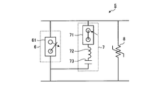
- FIG. 3 is a diagram illustrating a specific configuration example of the DC circuit breaker 5.
- the breaker unit 6 of the DC breaker 5 is constituted by a main breaker 61.
- the main breaker 61 cuts off the accident current when an accident occurs on the DC line in which the DC breaker 5 is inserted.
- the commutation unit 7 of the DC breaker 5 includes a closing switch 71, an inductance 72, and a capacitor 73.
- the commutation unit 7 generates a resonance current for forming a current zero point by superimposing it on the accident current when an accident occurs on the DC line in which the DC circuit breaker 5 is inserted.
- the energy absorption unit 8 is a lightning arrester as described above. The configuration shown in FIG.
- DC circuit breaker 3 is an example, and a DC circuit breaker having another configuration can be used as a test DC circuit breaker. That is, the DC circuit breaker that can be a test target of the DC circuit breaker test apparatus according to the present invention is not limited to the one shown in FIG.
- the main breaker 61 of the breaker unit 6 is in a closed state at normal times, that is, in a state where the DC breaker 5 is put into the actual system and no accident has occurred. Further, the closing switch 71 of the commutation unit 7 is normally open. The capacitor 73 is quickly charged by the charging circuit, which is not shown in FIG. 3, after the DC circuit breaker 5 is put into the actual system. When the closing switch 71 is closed in a state where charges are accumulated in the capacitor 73, the capacitor 73 is discharged, and a resonant current flows from the commutation unit 7 toward the cutoff unit 6.
- the main cut-off part 61 of the cut-off unit 6 and the closing switch 71 of the commutation unit 7 are controlled by a control device not shown in FIG.
- the control device that controls the main breaker 61 and the closing switch 71 detects that an accident has occurred in the DC line in which the DC breaker 5 is inserted, it instructs the main breaker 61 to open the circuit.
- the closing switch 71 is instructed to close.
- the closing switch 71 is closed, a resonant current flows from the commutation unit 7 to the main cutoff unit 61 to form a current zero point, and the cutoff of the accident current by the main cutoff unit 61 is completed.
- a change in the connection state of the main breaker 61 and the terminals of the closing switch 71 when an accident occurs in the DC line where the DC breaker 5 is turned on is indicated by an arrow.
- FIG. 3 Details of the operation when the test apparatus 100 for the DC circuit breaker according to the first exemplary embodiment tests the DC circuit breaker 5 shown in FIG. 3 are as shown in FIG.
- the control device 105 of the test apparatus 100 instructs the control device in the DC circuit breaker 5 to start the breaking operation, and the DC circuit breaker 5 that has received this instruction.
- the internal control device opens the main blocking unit 61 and turns on the closing switch 71.
- test circuit Before explaining the detailed operation of the test apparatus 100 according to the first embodiment, as a comparative example, the test circuit and operation for realizing the above-described AC short-circuit generator method and the ideal DC power supply method are realized. A test circuit will be described.
- FIG. 5 is a diagram showing a test circuit for realizing the AC short-circuit generator method.
- a DC circuit breaker 5 as a device under test is also shown.
- the configuration and operation of the DC circuit breaker 5 are the same as those of the DC circuit breaker 5 shown in FIGS.
- the test circuit shown in FIG. 5 includes an AC power supply 21 and a cutoff unit 24.
- the resistor 22 shown in FIG. 5 is a resistance component that the test circuit has, and the inductor 23 is an inductance component that the test circuit has.
- the AC power source 21 can be an AC short-circuit generator.
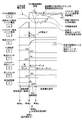
- FIG. 6 is a diagram illustrating an operation of the test circuit of the AC short-circuit generator method illustrated in FIG.
- FIG. 6 shows the waveforms of the current (i cb , i ar ) and voltage (V t ) of each part when the interruption test of the DC breaker 5 is carried out with the test circuit shown in FIG.
- the waveform of the energy (E ar ) and the operation sequence of each device of the test circuit and the DC circuit breaker 5 are shown.
- the change of the impedance is shown.
- FIG. 7 is a diagram showing a test circuit for realizing the ideal DC power supply method.
- a DC circuit breaker 5 as a device under test is also shown.
- the configuration and operation of the DC circuit breaker 5 are the same as those of the DC circuit breaker 5 shown in FIGS.
- the test circuit shown in FIG. 7 includes a DC power supply 31 and a blocking unit 34.
- the resistor 32 shown in FIG. 7 is a resistance component that the test circuit has, and the inductor 33 is an inductance component that the test circuit has.
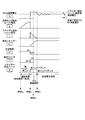
- FIG. 8 is a diagram showing the operation of the ideal DC power supply method test circuit shown in FIG.
- FIG. 8 shows the waveforms of the current (i cb , i ar ) and voltage (V t ) of each part when the interruption test of the DC circuit breaker 5 is performed by the test circuit shown in FIG.
- the waveform of the energy (E ar ) and the operation sequence of each device of the test circuit and the DC circuit breaker 5 are shown.
- the energy absorption unit 8 described in the lowermost stage shows a change in impedance.
- the ideal DC power supply method is virtually impossible to configure with the equipment of a high power laboratory, but it reproduces the basic phenomenon of an actual HVDC system as it is.
- the current, voltage, and energy waveform of each part obtained by the power supply method is an ideal reference waveform.
- the test waveform assumed to be obtained by the test circuit of the AC short-circuit generator method shown in FIG. 6 is compared with the ideal reference waveform shown in FIG. 8, the test waveform shown in FIG. (Time t 1 to time t 2 in the case of FIG. 6, time t 1 to time t 3 in the case of FIG. 8) and the recovery voltage period thereafter, the inter-electrode voltage (V t ) of the DC circuit breaker 5 is as shown in FIG. Does not include the ideal reference waveform. Also, due to that, the absorbed energy (E ar ) of the energy absorption unit of the DC circuit breaker 5 is also smaller than the ideal reference waveform. This indicates that the test using the AC short-circuit generator method cannot be performed under conditions close to the actual environment.
- Non-Patent Document 2 describes the stress applied to the DC breaker to be tested when the fault current interruption phenomenon in the HVDC real system is reproduced by a high power test facility. According to the description in Non-Patent Document 2, it is said that the total stress imposed on the DC circuit breaker in the interruption process of the interruption test can be defined by the following items (a) to (c).
- (A) Breaking current waveform flowing in the breaker unit of the DC breaker A
- TRV Transient recovery voltage waveform generated between the DC breaker poles after the breaking unit cuts off the current, and the subsequent recovery voltage waveform
- C Processing energy of the energy absorption unit installed in parallel with the breaker unit and commutation unit of the DC breaker
- a waveform equivalent to the actual system that is, a waveform corresponding to the waveform of icb shown in FIG.
- the (i), i.e., the waveform of V t shown in FIG. 6, in particular the duration of the transient recovery voltage (TRV duration) is shorter than HVDC actual system behavior, the real system and equivalent stress Cannot be applied to the DC breaker under test.
- the duration of the transient recovery voltage is determined by the following factors (1) to (4).
- the power supply side voltage waveform of (2) becomes larger as compared to the HVDC actual system (DC constant voltage), that is, AC short-circuit power generation.
- the absorbed energy becomes smaller as the recovery voltage duration of (b) above, that is, the operation time of the energy absorption unit is shorter, and the equivalence to the HVDC actual system becomes lower.
- the power supply side voltage vibrates at that frequency, so the voltage across the DC circuit breaker also oscillates in the recovery voltage region after the transient recovery voltage duration. It becomes.
- the recovery voltage is a direct current and has a constant waveform, and therefore, a stress equivalent to that in the HVDC real system cannot be applied to the recovery voltage region.
- testing cannot be performed under conditions close to the actual environment, or a vast amount of equipment is required for testing under conditions close to the actual environment. Is necessary and difficult to implement.
- the voltage source circuit 10 is connected in parallel to the DC circuit breaker 5 to be tested. Yes.
- the duration of the transient recovery voltage (b) obtained by the conventional AC short-circuit generator method test is extended to the equivalent of the ideal reference waveform, and the processing energy of the energy absorption unit (c) is changed to the ideal standard. It is possible to compensate to the waveform equivalent, and to improve the equivalence of the test.
- the test apparatus 100 when the test apparatus 100 performs a current interruption test of the DC breaker 5, the test apparatus 100 operates at time t in the state where the auxiliary breaker 4 is ON or closed and the closing switch 9 is OFF or opened.
- the operation of the AC power source 1 is started and the first test current starts to flow through the line in which the DC breaker 5 is inserted, and the test is started.
- the main circuit breaker 61 of the DC circuit breaker 5 is closed and the closing switch 71 is opened.
- the test apparatus 100 at time t 4 is a timing defined within the duration of the transient recovery voltage (TRV duration), the control device 105 closes the start switch 9.
- the voltage source circuit 10 of the second test current generator 102 is turned on, and the energy accumulated in the capacitor 13 of the voltage source circuit 10 is used as the current i h that is the second test current.
- the energy absorption unit 8 is injected.
- the test apparatus 100 the current i s greet current zero point in time t 2, the by closing the auxiliary circuit breaker 4, in time t 2, the, or at its front and rear, disconnect the AC power supply 1 from the DC circuit breaker 5 .
- the auxiliary circuit breaker 4 blocks the AC current that is the first test current flowing from the AC power source 1 to the DC circuit breaker 5.
- the injection of the energy stored in the capacitor 13 into the energy absorption unit 8 is started, thereby extending the TRV continuation time and the current conduction time of the energy absorption unit 8.
- the energy absorbed by the energy absorption unit 8 increases due to the TRV duration and the extension of the current conduction time of the energy absorption unit 8.
- the TRV duration and the amount of energy absorbed by the energy absorption unit 8 depend on the voltage of the capacitor 13 at the start of the test and the timing at which the closing switch 9 is turned on. Therefore, the time t 4 at which the closing switch 9 is turned on, and the voltage of the capacitor 13 at the time of starting the test, that is, the voltage at which the charging circuit 104 shown in FIG. 8 is equal to or longer than the TRV duration shown in FIG. 8, and the energy absorbed by the energy absorption unit 8 (absorbed energy E ar ) is equal to or greater than the absorbed energy E ar shown in FIG. Determined by simulation.
- the voltage of the capacitor 13 at the start of the test is set to a value larger than at least the limit voltage of the lightning arrester that is the energy absorption unit 8. By setting the voltage of the capacitor 13 at the start of the test to a value larger than the limit voltage of the lightning arrester, the energy discharged from the capacitor 13 is injected into the lightning arrester.
- the test apparatus 100 includes the first test current generation unit 101 and the second test current generation unit 102, and first performs the first test when the DC circuit breaker is tested.
- a first test current is supplied from the current generator 101 to the DC circuit breaker 5 of the device under test, and then a DC second test current is supplied from the second test current generator 102 at a specified timing to the device under test. It was decided to flow through the DC breaker 5.
- the waveform of the transient recovery voltage (TRV) obtained by the first test current that is the same test current as the test circuit that performs the test by the conventional AC short-circuit generator method is extended to the equivalent of the ideal reference waveform,
- the energy injected into the energy absorption unit 8 can be increased. Therefore, it is possible to apply a stress close to the DC circuit breaker of the device under test during operation in the actual system.
- FIG. 9 is a diagram illustrating a configuration example of a test apparatus for a DC circuit breaker according to the second embodiment.
- the test apparatus 100a according to the second embodiment illustrated in FIG. 9 is obtained by replacing the second test current generation unit 102 of the test apparatus 100 according to the first embodiment with a second test current generation unit 102a.
- the test apparatus 100a includes a charging circuit for charging a capacitor inside the second test current generation unit 102a, similarly to the test apparatus 100 according to the first embodiment. I have. Since the second test current generation unit 102a is the same as that of the first embodiment except for the second test current generation unit 102a, the second test current generation unit 102a will be described in this embodiment, and the description of the other components will be omitted.
- the second test current generation unit 102a is obtained by adding a circuit composed of an input switch 9a and a voltage source circuit 10a to the second test current generation unit 102.
- the closing switch 9 a is the same switch as the closing switch 9.
- the voltage source circuit 10 a is a circuit having a configuration in which a waveform adjusting reactor 11 a, a waveform adjusting resistor 12 a, and a capacitor 13 a are connected in series, and is the same circuit as the voltage source circuit 10.
- the constants of reactor 11a, resistor 12a and capacitor 13a are the same as reactor 11, resistor 12 and capacitor 13, but are not essential. Different constants may be used for the voltage source circuit 10 and the voltage source circuit 10a.
- the circuit composed of the switch 9a and the voltage source circuit 10a is the same circuit as the DC current generator circuit that is a circuit composed of the switch 9 and the voltage source circuit 10.
- the direct current generating circuit including the closing switch 9 a and the voltage source circuit 10 a is connected in parallel with the direct current generating circuit including the closing switch 9 and the voltage source circuit 10. Therefore, the second test current generation unit 102a corresponds to the second test current generation unit 102 described in Embodiment 1 in two stages.
- the second test current is injected into the DC circuit breaker 5 of the device under test in two portions.
- the closing switch 9 is closed at the first specified time within the TRV duration, and accumulated in the capacitor 13. Is injected into the energy absorption unit 8 of the DC circuit breaker 5 as a second test current.
- the closing switch 9a is closed at the second specified time within the TRV duration, and the energy stored in the capacitor 13a is injected into the energy absorption unit 8 of the DC circuit breaker 5 as the second test current.
- the order of closing the closing switches 9 and 9a may be reversed.
- the first specified time, the second specified time, and the voltages of the capacitors 13 and 13a at the start of the test are determined by simulation, as in the first embodiment.
- the voltage of the capacitors 13 and 13a at the start of the test is set to a value that is at least larger than the limit voltage of the lightning arrester that is the energy absorption unit 8.
- FIG. 9 shows an example in which the circuit (the input switch and the voltage source circuit) for generating the second test current has a two-stage configuration, a configuration having three or more stages may be used.
- the test apparatus 100a includes a plurality of voltage source circuits that generate the second test current, and injects the second test current in two or more times.
- the transient recovery voltage duration is shorter than the ideal reference waveform simply by injecting the second test current from the first-stage voltage source circuit to the energy absorption unit 8 of the DC circuit breaker 5.
- the TRV duration can be further extended.
- the second test current is injected from the first-stage voltage source circuit to the energy absorption unit 8 of the DC circuit breaker 5, and the second-stage voltage source circuit is at a timing before the end of the TRV duration.
- the TRV duration can be further extended to approach the ideal reference waveform.
- the configuration described in the above embodiment shows an example of the contents of the present invention, and can be combined with another known technique, and can be combined with other configurations without departing from the gist of the present invention. It is also possible to omit or change the part.
Landscapes
- Tests Of Circuit Breakers, Generators, And Electric Motors (AREA)
- Arc-Extinguishing Devices That Are Switches (AREA)
- Emergency Protection Circuit Devices (AREA)
Abstract
L'invention concerne un dispositif de test (100) pour disjoncteur à courant continu, qui comprend : une source d'alimentation en courant alternatif (1) pour générer un premier courant de test à fournir au disjoncteur à courant continu (5) à tester ; un circuit source de tension (10) pour générer un second courant de test à fournir au disjoncteur à courant continu ; et un interrupteur d'entrée (9) qui est disposé entre le circuit source de tension et le disjoncteur à courant continu et qui est dans un état ouvert à un instant auquel le premier courant de test commence à circuler de la source de courant alternatif au disjoncteur à courant continu, et passe dans un état fermé un temps prédéterminé après que le disjoncteur à courant continu a coupé le premier courant de test, connectant ainsi le circuit source de tension au disjoncteur à courant continu. Lorsque l'interrupteur d'entrée se ferme, le circuit source de tension amène un condensateur (13), qui a été chargé à une tension supérieure à une tension limite d'une unité d'absorption d'énergie (8) du disjoncteur à courant continu, à se décharger afin de générer le second courant de test.
Priority Applications (2)
| Application Number | Priority Date | Filing Date | Title |
|---|---|---|---|
| PCT/JP2016/064901 WO2017199397A1 (fr) | 2016-05-19 | 2016-05-19 | Dispositif de test et procédé de test pour disjoncteur à courant continu |
| JP2016555393A JP6042047B1 (ja) | 2016-05-19 | 2016-05-19 | 直流遮断器の試験装置および試験方法 |
Applications Claiming Priority (1)
| Application Number | Priority Date | Filing Date | Title |
|---|---|---|---|
| PCT/JP2016/064901 WO2017199397A1 (fr) | 2016-05-19 | 2016-05-19 | Dispositif de test et procédé de test pour disjoncteur à courant continu |
Publications (1)
| Publication Number | Publication Date |
|---|---|
| WO2017199397A1 true WO2017199397A1 (fr) | 2017-11-23 |
Family
ID=57543798
Family Applications (1)
| Application Number | Title | Priority Date | Filing Date |
|---|---|---|---|
| PCT/JP2016/064901 Ceased WO2017199397A1 (fr) | 2016-05-19 | 2016-05-19 | Dispositif de test et procédé de test pour disjoncteur à courant continu |
Country Status (2)
| Country | Link |
|---|---|
| JP (1) | JP6042047B1 (fr) |
| WO (1) | WO2017199397A1 (fr) |
Cited By (6)
| Publication number | Priority date | Publication date | Assignee | Title |
|---|---|---|---|---|
| CN108196177A (zh) * | 2017-12-26 | 2018-06-22 | 华北电力大学 | 一种半导体组件性能测试系统 |
| CN109031105A (zh) * | 2018-06-12 | 2018-12-18 | 江苏启源雷宇电气科技有限公司 | 一种直流断路器电流开断实验平台 |
| CN109709425A (zh) * | 2018-12-29 | 2019-05-03 | 国网冀北电力有限公司电力科学研究院 | 一种配电变压器承受短路能力的试验系统及方法 |
| CN110346714A (zh) * | 2019-08-22 | 2019-10-18 | 云南电网有限责任公司电力科学研究院 | 模拟断路器工况运行方法、装置以及线路系统、测试设备 |
| CN110376512A (zh) * | 2019-07-10 | 2019-10-25 | 中国南方电网有限责任公司超高压输电公司检修试验中心 | 一种直流高速开关直流空充电流开断试验回路 |
| WO2019206552A1 (fr) * | 2018-04-25 | 2019-10-31 | Bayerische Motoren Werke Aktiengesellschaft | Dispositif d'essai et procédé d'essai synthétique d'au moins un dispositif de commutation pour une batterie haute tension d'un véhicule automobile |
Families Citing this family (3)
| Publication number | Priority date | Publication date | Assignee | Title |
|---|---|---|---|---|
| WO2018146748A1 (fr) * | 2017-02-08 | 2018-08-16 | 三菱電機株式会社 | Dispositif de test et procédé de test pour disjoncteur cc |
| CN111505492B (zh) * | 2020-04-27 | 2022-02-18 | 南京南瑞继保电气有限公司 | 一种直流断路器测试装置及方法 |
| CN112653083B (zh) * | 2020-12-08 | 2025-08-01 | 李川 | 一种10kv断路器快速分断装置与实现方法 |
Citations (2)
| Publication number | Priority date | Publication date | Assignee | Title |
|---|---|---|---|---|
| JPS5049667A (fr) * | 1973-07-19 | 1975-05-02 | ||
| JP2015059891A (ja) * | 2013-09-20 | 2015-03-30 | 株式会社東芝 | 直流遮断器の試験装置及び直流遮断器の試験装置による試験方法 |
-
2016
- 2016-05-19 WO PCT/JP2016/064901 patent/WO2017199397A1/fr not_active Ceased
- 2016-05-19 JP JP2016555393A patent/JP6042047B1/ja active Active
Patent Citations (2)
| Publication number | Priority date | Publication date | Assignee | Title |
|---|---|---|---|---|
| JPS5049667A (fr) * | 1973-07-19 | 1975-05-02 | ||
| JP2015059891A (ja) * | 2013-09-20 | 2015-03-30 | 株式会社東芝 | 直流遮断器の試験装置及び直流遮断器の試験装置による試験方法 |
Cited By (9)
| Publication number | Priority date | Publication date | Assignee | Title |
|---|---|---|---|---|
| CN108196177A (zh) * | 2017-12-26 | 2018-06-22 | 华北电力大学 | 一种半导体组件性能测试系统 |
| WO2019206552A1 (fr) * | 2018-04-25 | 2019-10-31 | Bayerische Motoren Werke Aktiengesellschaft | Dispositif d'essai et procédé d'essai synthétique d'au moins un dispositif de commutation pour une batterie haute tension d'un véhicule automobile |
| US11733299B2 (en) | 2018-04-25 | 2023-08-22 | Bayerische Motoren Werke Aktiengesellschaft | Test apparatus and method for synthetically testing at least one switch device for a high-voltage battery of a vehicle |
| CN109031105A (zh) * | 2018-06-12 | 2018-12-18 | 江苏启源雷宇电气科技有限公司 | 一种直流断路器电流开断实验平台 |
| CN109709425A (zh) * | 2018-12-29 | 2019-05-03 | 国网冀北电力有限公司电力科学研究院 | 一种配电变压器承受短路能力的试验系统及方法 |
| CN109709425B (zh) * | 2018-12-29 | 2020-05-22 | 国网冀北电力有限公司电力科学研究院 | 一种配电变压器承受短路能力的试验系统及方法 |
| CN110376512A (zh) * | 2019-07-10 | 2019-10-25 | 中国南方电网有限责任公司超高压输电公司检修试验中心 | 一种直流高速开关直流空充电流开断试验回路 |
| CN110376512B (zh) * | 2019-07-10 | 2024-04-26 | 中国南方电网有限责任公司超高压输电公司检修试验中心 | 一种直流高速开关直流空充电流开断试验回路 |
| CN110346714A (zh) * | 2019-08-22 | 2019-10-18 | 云南电网有限责任公司电力科学研究院 | 模拟断路器工况运行方法、装置以及线路系统、测试设备 |
Also Published As
| Publication number | Publication date |
|---|---|
| JP6042047B1 (ja) | 2016-12-14 |
| JPWO2017199397A1 (ja) | 2018-05-31 |
Similar Documents
| Publication | Publication Date | Title |
|---|---|---|
| JP6042047B1 (ja) | 直流遮断器の試験装置および試験方法 | |
| CN101706541B (zh) | 一种直流输电换流阀故障电流实验检测装置 | |
| JP6645758B2 (ja) | 直流遮断器の試験方法 | |
| CN110286320B (zh) | 具有保护功能的直流断路器半导体组件关断能力测试回路 | |
| DK3230999T3 (en) | POWER SUPPLY FOR HIGH VOLTAGE DC | |
| JP6767644B2 (ja) | 直流遮断器の試験装置 | |
| EP4054037B1 (fr) | Disjoncteur à cc | |
| Tokoyoda et al. | Interruption characteristics of vacuum circuit breaker and the application to DCCB | |
| JP5677148B2 (ja) | コンデンサバンク開閉性能試験装置 | |
| CN201724990U (zh) | 一种直流输电换流阀故障电流实验检测装置 | |
| Bedran et al. | Type tests of the ITER switching network unit components and protective make switches | |
| JP2016213123A (ja) | 直流遮断器の試験装置及びその試験方法 | |
| JPH08271596A (ja) | 遮断器の合成等価試験法 | |
| Liang et al. | Synthetic test for DC vacuum circuit breaker with three power supply sources | |
| JP7325937B2 (ja) | 真空遮断器の投入試験装置およびその試験方法 | |
| JP2675649B2 (ja) | 開閉装置の試験方法およびその装置 | |
| CN106099910B (zh) | 三相交流电源切换电路及其驱动方法、电源切换装置 | |
| JPH03202792A (ja) | しゃ断器の合成試験装置 | |
| JPH08278349A (ja) | 遮断器の合成等価試験法 | |
| JP2012194076A (ja) | 開閉装置の試験装置及びその試験方法 | |
| Jiang et al. | Optimization Design for a High Voltage DC Power Supply Module Based on PSM Technology | |
| WO2018146748A1 (fr) | Dispositif de test et procédé de test pour disjoncteur cc | |
| RU2478216C1 (ru) | Устройство для определения характеристик вакуумных выключателей | |
| CN120044384A (zh) | 一种可控换相换流阀非周期触发试验装置及方法 | |
| JPH0519029A (ja) | 遮断器の合成等価試験回路 |
Legal Events
| Date | Code | Title | Description |
|---|---|---|---|
| ENP | Entry into the national phase |
Ref document number: 2016555393 Country of ref document: JP Kind code of ref document: A |
|
| NENP | Non-entry into the national phase |
Ref country code: DE |
|
| 121 | Ep: the epo has been informed by wipo that ep was designated in this application |
Ref document number: 16902416 Country of ref document: EP Kind code of ref document: A1 |
|
| 122 | Ep: pct application non-entry in european phase |
Ref document number: 16902416 Country of ref document: EP Kind code of ref document: A1 |