WO2017199428A1 - 可変速増速機 - Google Patents
可変速増速機 Download PDFInfo
- Publication number
- WO2017199428A1 WO2017199428A1 PCT/JP2016/065020 JP2016065020W WO2017199428A1 WO 2017199428 A1 WO2017199428 A1 WO 2017199428A1 JP 2016065020 W JP2016065020 W JP 2016065020W WO 2017199428 A1 WO2017199428 A1 WO 2017199428A1
- Authority
- WO
- WIPO (PCT)
- Prior art keywords
- speed
- variable speed
- shaft
- motor
- rotational speed
- Prior art date
- Legal status (The legal status is an assumption and is not a legal conclusion. Google has not performed a legal analysis and makes no representation as to the accuracy of the status listed.)
- Ceased
Links
Images


Classifications
-
- F—MECHANICAL ENGINEERING; LIGHTING; HEATING; WEAPONS; BLASTING
- F16—ENGINEERING ELEMENTS AND UNITS; GENERAL MEASURES FOR PRODUCING AND MAINTAINING EFFECTIVE FUNCTIONING OF MACHINES OR INSTALLATIONS; THERMAL INSULATION IN GENERAL
- F16H—GEARING
- F16H3/00—Toothed gearings for conveying rotary motion with variable gear ratio or for reversing rotary motion
- F16H3/44—Toothed gearings for conveying rotary motion with variable gear ratio or for reversing rotary motion using gears having orbital motion
- F16H3/72—Toothed gearings for conveying rotary motion with variable gear ratio or for reversing rotary motion using gears having orbital motion with a secondary drive, e.g. regulating motor, in order to vary speed continuously
- F16H3/724—Toothed gearings for conveying rotary motion with variable gear ratio or for reversing rotary motion using gears having orbital motion with a secondary drive, e.g. regulating motor, in order to vary speed continuously using externally powered electric machines
- F16H3/725—Toothed gearings for conveying rotary motion with variable gear ratio or for reversing rotary motion using gears having orbital motion with a secondary drive, e.g. regulating motor, in order to vary speed continuously using externally powered electric machines with means to change ratio in the mechanical gearing
-
- F—MECHANICAL ENGINEERING; LIGHTING; HEATING; WEAPONS; BLASTING
- F16—ENGINEERING ELEMENTS AND UNITS; GENERAL MEASURES FOR PRODUCING AND MAINTAINING EFFECTIVE FUNCTIONING OF MACHINES OR INSTALLATIONS; THERMAL INSULATION IN GENERAL
- F16H—GEARING
- F16H3/00—Toothed gearings for conveying rotary motion with variable gear ratio or for reversing rotary motion
- F16H3/44—Toothed gearings for conveying rotary motion with variable gear ratio or for reversing rotary motion using gears having orbital motion
- F16H3/72—Toothed gearings for conveying rotary motion with variable gear ratio or for reversing rotary motion using gears having orbital motion with a secondary drive, e.g. regulating motor, in order to vary speed continuously
- F16H3/724—Toothed gearings for conveying rotary motion with variable gear ratio or for reversing rotary motion using gears having orbital motion with a secondary drive, e.g. regulating motor, in order to vary speed continuously using externally powered electric machines
-
- H—ELECTRICITY
- H02—GENERATION; CONVERSION OR DISTRIBUTION OF ELECTRIC POWER
- H02K—DYNAMO-ELECTRIC MACHINES
- H02K11/00—Structural association of dynamo-electric machines with electric components or with devices for shielding, monitoring or protection
- H02K11/20—Structural association of dynamo-electric machines with electric components or with devices for shielding, monitoring or protection for measuring, monitoring, testing, protecting or switching
- H02K11/21—Devices for sensing speed or position, or actuated thereby
-
- H—ELECTRICITY
- H02—GENERATION; CONVERSION OR DISTRIBUTION OF ELECTRIC POWER
- H02K—DYNAMO-ELECTRIC MACHINES
- H02K7/00—Arrangements for handling mechanical energy structurally associated with dynamo-electric machines, e.g. structural association with mechanical driving motors or auxiliary dynamo-electric machines
- H02K7/10—Structural association with clutches, brakes, gears, pulleys or mechanical starters
- H02K7/116—Structural association with clutches, brakes, gears, pulleys or mechanical starters with gears
-
- F—MECHANICAL ENGINEERING; LIGHTING; HEATING; WEAPONS; BLASTING
- F16—ENGINEERING ELEMENTS AND UNITS; GENERAL MEASURES FOR PRODUCING AND MAINTAINING EFFECTIVE FUNCTIONING OF MACHINES OR INSTALLATIONS; THERMAL INSULATION IN GENERAL
- F16H—GEARING
- F16H2200/00—Transmissions for multiple ratios
- F16H2200/20—Transmissions using gears with orbital motion
- F16H2200/2002—Transmissions using gears with orbital motion characterised by the number of sets of orbital gears
- F16H2200/2005—Transmissions using gears with orbital motion characterised by the number of sets of orbital gears with one sets of orbital gears
-
- F—MECHANICAL ENGINEERING; LIGHTING; HEATING; WEAPONS; BLASTING
- F16—ENGINEERING ELEMENTS AND UNITS; GENERAL MEASURES FOR PRODUCING AND MAINTAINING EFFECTIVE FUNCTIONING OF MACHINES OR INSTALLATIONS; THERMAL INSULATION IN GENERAL
- F16H—GEARING
- F16H2200/00—Transmissions for multiple ratios
- F16H2200/20—Transmissions using gears with orbital motion
- F16H2200/2002—Transmissions using gears with orbital motion characterised by the number of sets of orbital gears
- F16H2200/2007—Transmissions using gears with orbital motion characterised by the number of sets of orbital gears with two sets of orbital gears
Definitions
- the present invention relates to a variable speed step-up gear provided with an electric device composed of a constant-speed electric motor and a variable-speed electric motor, and a planetary gear transmission that changes the rotational driving force generated by the electric device and transmits it to an object to be driven.
- Japanese Patent Application Laid-Open No. H10-228561 describes a device using a constant speed motor and a variable speed motor for shifting as an electric device and using a planetary gear transmission as a transmission device in order to accurately control the gear ratio.
- the rotational speed of the output shaft of the planetary gear transmission connected to the rotating machine can be changed by changing the rotational speed of the variable speed electric motor.
- the compressor when the compressor is driven using the above variable speed step-up gear, for example, it is not preferable to reversely rotate the output shaft of the planetary gear transmission. However, for example, when the rotation of the output shaft is stopped, the output shaft may rotate in the reverse direction.
- the present invention relates to a planetary gear in a variable speed gear that includes an electric device composed of a constant speed motor and a variable speed motor, and a planetary gear transmission that shifts the rotational driving force generated by the electric device and transmits the rotational driving force to a drive target.
- An object of the present invention is to provide a variable speed step-up gear capable of preventing the output shaft of a transmission from rotating in reverse.
- a variable speed step-up gear includes: an electric device that generates rotational driving force; and a transmission that shifts the rotational driving force generated by the electric device and transmits the rotational driving force to a drive target.
- the transmission includes a sun gear that rotates about an axis, a sun gear shaft that is fixed to the sun gear, extends in the axial direction about the axis, meshes with the sun gear, and is centered on the axis.
- a planetary gear carrier having an axis and supporting the planetary gear so that it can revolve around the axis and rotate around the centerline of the planetary gear itself; and an axis around the axis
- An internal gear carrier shaft extending in the direction, and an internal gear carrier that supports the internal gear so as to be capable of rotating about the axis, and an output shaft to which the sun gear shaft is connected to the drive target.
- the internal gear carrier shaft forms a constant speed input shaft
- the planetary gear carrier shaft forms a variable speed input shaft
- the electric device moves the constant speed input shaft of the transmission in a second direction.
- a constant-speed electric motor having a constant-speed rotor to be rotated; a variable-speed rotor connected to the variable-speed input shaft of the transmission; and the variable-speed rotor in a first direction opposite to the second direction.
- the variable speed electric motor that rotates the output shaft at the maximum rotational speed
- the output shaft rotational speed sensor that measures the rotational speed ⁇ s of the output shaft, and the rotational speed ⁇ h of the variable speed electric motor.
- Variable speed motor speed sensor to measure Among the constant-speed motor rotational speed sensors that measure the rotational speed ⁇ i of the constant-speed motor, at least two rotational speed sensors, and the rotational speed ⁇ s of the output shaft and the variable-speed electric motor based on the measured values of the rotational speed sensor
- Such a configuration can prevent the output shaft from rotating in the reverse direction.
- variable speed rotor may have a cylindrical shape centered on the axis, and the constant speed input shaft may be inserted into a shaft insertion hole that penetrates in the axial direction.
- variable speed step-up gear 1 includes an electric device 50 that generates a rotational driving force, and a transmission device 10 that shifts the rotational driving force generated by the electric device 50 and transmits it to a drive target.
- the variable speed increaser 1 can be applied to a fluid mechanical system such as a compressor system, for example.
- the driving target of the variable speed increaser 1 of the present embodiment is the compressor C.
- the transmission 10 is a planetary gear transmission.
- the electric device 50 includes a constant speed motor 51 having a constant speed rotor 52 that rotates at a constant speed, and a variable speed motor 71 having a variable speed rotor 72 that rotates at an arbitrary rotational speed.
- the constant speed rotor 52 and the variable speed rotor 72 are each connected to the transmission 10.
- the electric device 50 is supported on the gantry 90 by the electric device support portion 50S.
- the transmission 10 is supported on the gantry 90 by the transmission support 10S.
- the transmission 10 is in mesh with the sun gear 11 that rotates about an axis Ar that extends in the horizontal direction, the sun gear shaft 12 that is fixed to the sun gear 11, and the sun gear 11.
- a plurality of planetary gears 15 revolving around the axis Ar and rotating around the centerline Ap; an internal gear 17 in which a plurality of teeth are arranged in an annular shape around the axis Ar and meshed with the plurality of planetary gears 15;
- a planetary gear carrier 21 that supports a plurality of planetary gears 15 so that they can revolve around an axis Ar and that can rotate around a centerline Ap of the planetary gear 15 itself, and an internal gear 17 that can rotate around an axis Ar. It has an internal gear carrier 31 to be supported and a speed change casing 41 covering these.
- the direction in which the axis Ar extends is the axial direction, one side of the axial direction is the output side, and the opposite side of the output side is the input side.
- the radial direction centered on the axis Ar is simply referred to as the radial direction.
- the electric device 50 is disposed on the input side in the axial direction
- the transmission 10 is disposed on the output side of the electric device 50.
- the compressor C is disposed on the output side of the variable speed gear 1.
- the sun gear shaft 12 has a cylindrical shape centered on the axis Ar, and extends from the sun gear 11 to the output side in the axial direction.
- a flange 13 is formed at the output side end of the sun gear shaft 12.
- a rotor of a compressor C as a driving target is connected to the flange 13.
- the sun gear shaft 12 is supported by a sun gear bearing 42 disposed on the output side of the sun gear 11 so as to be rotatable about the axis Ar.
- the sun gear bearing 42 is attached to the transmission casing 41.
- the planetary gear carrier 21 includes a planetary gear shaft 22 provided for each of the plurality of planetary gears 15, a carrier body 23 that fixes the positions of the plurality of planetary gear shafts 22, and an output that extends in the axial direction about the axis Ar. And a side planetary gear carrier shaft 27o.
- the output planetary gear carrier shaft 27o is fixed to the inside of the carrier body 23 in the radial direction.
- the planetary gear shaft 22 penetrates the center line Ap of the planetary gear 15 in the axial direction, and supports the planetary gear 15 so as to be rotatable about the centerline.
- the carrier body 23 extends radially outward from the plurality of planetary gear shafts 22.
- the output-side planetary gear carrier shaft 27o extends from the carrier body 23 to the output side.
- the output-side planetary gear carrier shaft 27o has a cylindrical shape with the axis line Ar as the center.
- the output side planetary gear carrier shaft 27o is supported by a planetary gear carrier bearing 43 so as to be capable of rotating about the axis Ar.
- the planetary gear carrier bearing 43 is attached to the transmission casing 41.
- the sun gear shaft 12 is inserted into the inner peripheral side of the output side planetary gear carrier shaft 27o.
- the transmission 10 includes an input-side planetary gear carrier shaft 27i connected to the variable-speed rotor 72 of the variable-speed motor 71, and a transmission shaft 25 that transmits the rotation of the input-side planetary gear carrier shaft 27i to the planetary gear carrier 21.
- the input side planetary gear carrier shaft 27i has a cylindrical shape with the axis line Ar as the center.
- the input-side planetary gear carrier shaft 27i is disposed on the input side of the transmission 10, and is supported by the planetary gear carrier bearing 44 so as to be rotatable about the axis Ar.
- the planetary gear carrier bearing 44 is attached to the transmission casing 41.
- An internal gear carrier shaft 37 that drives the internal gear carrier 31 of the transmission 10 is inserted through the inner peripheral side of the input-side planetary gear carrier shaft 27i.
- An annular flange 28 is formed on the input side end of the input side planetary gear carrier shaft 27i so as to expand outward in the radial direction.
- An input side arm portion 26 extending outward in the radial direction is formed at the output side end of the input side planetary gear carrier shaft 27i.
- the transmission shaft 25 is supported so as to be capable of rotating about the axis At.
- the transmission shaft 25 is attached to the transmission casing 41 via a bearing (not shown).
- An input side transmission gear 29 i and an output side transmission gear 29 o are fixed to both ends of the transmission shaft 25.
- the input side transmission gear 29 i meshes with a gear formed on the outer periphery of the input side arm portion 26.
- the output transmission gear 29o meshes with a gear formed on the outer periphery of the carrier body 23.
- the internal gear carrier 31 has a carrier main body 33 to which the internal gear 17 is fixed, and an internal gear carrier shaft 37 that is fixed to the carrier main body 33 and extends in the axial direction about the axis Ar.
- the carrier body 33 has a cylindrical shape centered on the axis Ar, a cylindrical portion 35 in which the internal gear 17 is fixed on the inner peripheral side, and an input side arm portion that extends radially inward from the input side end of the cylindrical portion 35. 36.
- the internal gear carrier shaft 37 having a cylindrical shape with the axis line Ar as the center is disposed on the input side of the sun gear shaft 12 having a cylindrical shape with the axis line Ar as the center.
- the input side arm portion 36 of the carrier body 33 is fixed to the internal gear carrier shaft 37.
- the internal gear carrier shaft 37 is inserted into the inner peripheral side of the cylindrical input side planetary gear carrier shaft 27i.
- the constant speed motor 51 rotates the internal gear carrier shaft 37 of the transmission 10.
- the variable speed motor 71 rotates the input planetary gear carrier shaft 27 i of the transmission 10.
- the electric device 50 includes a cooling fan 91 for cooling the constant speed electric motor 51 and a fan cover 92 that covers the cooling fan 91.
- the internal gear carrier shaft 37 is a constant speed input shaft Ac that rotates at a constant speed by the driving force of the constant speed motor 51.
- the input-side planetary gear carrier shaft 27 i is a variable speed input shaft Av that rotates at an arbitrary rotation speed by the driving force of the variable speed motor 71.
- the variable speed gearbox 1 can change the rotation speed of the output shaft Ao of the transmission 10 connected to the drive target by changing the rotation speed of the variable speed motor 71.
- the constant speed motor 51 is, for example, a four-pole three-phase induction motor.
- the variable speed motor 71 is a six-pole three-phase induction motor having more poles than the constant speed motor 51.
- the specifications of the constant speed motor 51 and the variable speed motor 71 are not limited to this, and the specifications can be changed as appropriate.
- the constant speed motor 51 rotates around the axis line Ar, and is disposed on the outer peripheral side of the constant speed rotor 52 and the constant speed rotor 52 connected to the internal gear carrier shaft 37 that is the constant speed input shaft Ac of the transmission 10. And a constant speed motor casing 61 in which the constant speed stator 66 is fixed on the inner peripheral side.
- the constant-speed rotor 52 has a constant-speed rotor shaft 53 that forms a columnar shape about the axis Ar, and a conductor 56 that is fixed to the outer periphery of the constant-speed rotor shaft 53.
- a cooling fan 91 is fixed to the input side end of the constant speed rotor shaft 53.
- the constant speed stator 66 is disposed on the radially outer side of the conductor 56 of the constant speed rotor 52.
- the constant speed stator 66 is formed by a plurality of coils.
- the constant-speed motor casing 61 has a cylindrical shape centered on the axis Ar, a casing main body 62 in which a constant-speed stator 66 is fixed on the inner peripheral side, and a lid that covers both ends of the cylindrical casing main body 62 in the axial direction. 63i, 63o.
- Constant-speed rotor bearings 65i and 65o that support the constant-speed rotor shaft 53 so as to be capable of rotating about the axis Ar are attached to the respective lids 63i and 63o.
- Each of the lids 63i and 63o is formed with a plurality of openings 64 penetrating in the axial direction at positions radially outside the constant speed rotor bearing 65i.
- the input side end of the constant speed rotor shaft 53 protrudes from the input side lid 63 i of the constant speed motor casing 61 to the input side.
- a cooling fan 91 is fixed to the input side end of the constant speed rotor shaft 53. When the constant speed rotor 52 rotates, the cooling fan 91 also rotates integrally with the constant speed rotor 52.
- the fan cover 92 includes a cylindrical cover main body 93 disposed on the outer peripheral side of the cooling fan 91, and an air circulation plate 94 attached to an opening on the inlet side of the cover main body 93 and formed with a plurality of air holes. Have.
- the fan cover 92 is fixed to the input side lid 63 i of the constant speed motor casing 61.
- variable speed motor 71 rotates around the axis Ar, and is disposed on the outer peripheral side of the variable speed rotor 72 and the variable speed rotor 72 connected to the input side planetary gear carrier shaft 27i that is the variable speed input shaft Av.
- a variable speed stator 86 and a variable speed motor casing 81 in which the variable speed stator 86 is fixed on the inner peripheral side are provided.
- the variable speed rotor 72 has a variable speed rotor shaft 73 and a conductor 76 fixed to the outer periphery of the variable speed rotor shaft 73.
- the variable speed rotor shaft 73 has a cylindrical shape centering on the axis line Ar, and has a shaft insertion hole 74 penetrating in the axial direction.
- An internal gear carrier shaft 37 that is a constant speed input shaft Ac is inserted through the shaft insertion hole 74 of the variable speed rotor shaft 73.
- An annular flange 73o is formed at the output side end of the variable speed rotor shaft 73 so as to expand outward in the radial direction.
- the variable speed stator 86 is disposed on the radially outer side of the conductor 76 of the variable speed rotor 72.
- the variable speed stator 86 is formed of a plurality of coils.
- the variable speed motor casing 81 has a cylindrical shape centered on the axis Ar, a casing main body 82 in which a variable speed stator 86 is fixed on the inner peripheral side, and an output side that closes an output side end of the cylindrical casing main body 82. It has a lid 83o and an inlet side lid 83i that is arranged on the input side of the variable speed stator 86 and is fixed to the inner peripheral side of the cylindrical casing body 82.
- Variable speed rotor bearings 85i and 85o for supporting the variable speed rotor shaft 73 so as to be capable of rotating about the axis Ar are attached to the respective lids 83i and 83o.
- Each of the lids 83i, 83o is formed with a plurality of openings 84 penetrating in the axial direction at positions radially outside the variable speed rotor bearings 85i, 85o.
- the space in 81 communicates with the space in the constant speed motor casing 61.
- variable speed increaser 1 of the present embodiment the constant speed rotor 52, the variable speed rotor 72, and the sun gear shaft 12 are arranged on the same axis.
- the constant speed motor 51 is set to rotate the constant speed rotor 52 (internal gear 17) in the second direction R ⁇ b> 2 in the circumferential direction of the axis Ar by supplying electric power to the constant speed motor 51.
- the constant speed rotor 52 rotates in the second direction R2
- the internal gear carrier shaft 37 and the internal gear carrier 31 rotate in the second direction R2.
- the output shaft Ao of the transmission 10 is rotated in the first direction R1 opposite to the second direction R2 by the constant speed rotor 52 of the constant speed motor 51 rotating in the second direction R2 at the maximum rotation speed.
- the forward rotation of the constant speed motor 51 is the second direction R2
- the forward rotation of the output shaft Ao of the transmission 10 is the first direction R1.
- the compressor C operates normally when the output shaft Ao rotates forward.
- the rotation direction of the first direction R1 is a positive rotation direction
- the rotation direction of the second direction R2 is a negative rotation direction.
- the maximum rotation speed of the constant speed motor 51 is ⁇ 1800 rpm.
- the variable speed electric motor 71 can rotationally drive the variable speed rotor 72 (planetary gear carrier 21) in the first direction R1 and the second direction R2 in the circumferential direction of the axis Ar. That is, the variable speed electric motor 71 can rotate forward and backward.
- the variable speed motor 71 functions as a generator by rotating the variable speed rotor 72 in the second direction R2.
- a state in which the variable speed motor 71 functions as a generator is referred to as a generator mode. That is, the variable speed rotor 72 of the variable speed motor 71 rotates in the second direction R2 in the generator mode.
- the variable speed motor 71 functions as an electric motor by rotating the variable speed rotor 72 in the first direction R1.
- a state in which the variable speed motor 71 functions as a motor is referred to as a motor mode. That is, the variable speed rotor 72 of the variable speed motor 71 rotates in the first direction R1 in the motor mode. As the variable speed rotor 72 rotates in the first direction R1, the planetary gear carrier 21 rotates in the first direction R1.
- the variable speed gearbox 1 of the present embodiment includes a rotation speed control device 100 that controls the rotation speed of the variable speed motor 71, a variable speed motor switch 111 that sets the variable speed motor 71 in a power supply state and a power cut-off state, and A constant-speed motor switch 112 that puts the constant-speed motor 51 into a power supply state and a power-off state, a control unit 120 that controls operations of the rotation speed control device 100, the variable-speed motor switch 111, and the constant-speed motor switch 112; It has.
- the control unit 120 is composed of a computer.
- the control unit 120 receives an instruction from the operator directly or receives an instruction from the host control device, an interface 122 that gives an instruction to the variable speed motor switch 111, the rotation speed control device 100, and the constant speed motor switch 112.
- a calculation unit 123 that creates instructions for the variable speed motor switch 111, the constant speed motor switch 112, and the rotation speed control device 100 in accordance with the instructions received by the reception unit 121.
- variable speed motor switch 111 is electrically connected to the power line 110 and the rotation speed control device 100.
- the rotation speed control device 100 is electrically connected to the variable speed motor 71.
- the constant speed motor switch 112 is electrically connected to the power line 110 and the constant speed motor 51.
- the variable speed motor switch 111 is turned on by an on instruction from the control unit 120 and turned off by an off instruction from the control unit 120.
- the variable speed motor switch 111 When the variable speed motor switch 111 is turned on, power from the power line 110 is supplied to the variable speed motor 71 via the rotation speed control device 100, and the variable speed motor 71 is in a power supply state.
- the variable speed motor switch 111 When the variable speed motor switch 111 is turned off, the power supply from the power line 110 to the rotation speed control device 100 and the variable speed motor 71 is cut off, and the variable speed motor 71 enters a power cut-off state.
- the constant speed motor switch 112 is turned on by an on instruction from the control unit 120 and turned off by an off instruction from the control unit 120.
- the constant speed motor switch 112 When the constant speed motor switch 112 is turned on, the power from the power line 110 is supplied to the constant speed motor 51, and the constant speed motor 51 enters a power supply state.
- the constant-speed motor switch 112 When the constant-speed motor switch 112 is turned off, the power supply from the power line 110 to the constant-speed motor 51 is cut off, and the constant-speed motor 51 enters a power cut-off state.
- the rotation speed control device 100 includes a frequency conversion unit 101 that changes the frequency of power supplied from the power line 110 and a rotation direction change unit 102 that changes the rotation direction of the variable speed motor 71.
- the frequency conversion unit 101 supplies the variable speed electric motor 71 with electric power having a frequency instructed by the control unit 120.
- the variable speed rotor 72 of the variable speed motor 71 rotates at a rotational speed corresponding to this frequency.
- the rotation speed of the planetary gear carrier 21 of the transmission 10 connected to the variable speed rotor 72 also changes.
- the rotational speed of the sun gear shaft 12 that is the output shaft Ao of the transmission 10 also changes.
- the rotation direction changing unit 102 is a device that changes the rotation direction of the variable speed motor 71 by using a circuit that replaces a plurality of (three in the present embodiment) power lines connected to the variable speed motor 71. . That is, the rotation direction changing unit 102 can rotate the variable speed rotor 72 forward and backward.
- the variable speed step-up gear 1 includes an output shaft rotational speed sensor 131 that measures the rotational speed of the output shaft Ao. Moreover, the variable speed gearbox 1 of this embodiment is provided with the constant speed motor rotation speed sensor 132 which measures the rotation speed of the constant speed motor 51 (constant speed rotor 52). Moreover, the variable speed step-up gear 1 of the present embodiment includes a variable speed motor rotational speed sensor 133 that measures the rotational speed of the variable speed electric motor 71 (variable speed rotor 72). The rotational speed measured by these rotational speed sensors is transmitted to the control unit 120.
- the control unit 120 of the variable speed increaser 1 Based on the measurement value measured by the rotation speed sensor, the control unit 120 of the variable speed increaser 1 according to the present embodiment reverses the rotation axis of the compressor C connected to the output shaft Ao and the output shaft Ao ( It has a function of preventing rotation in the second direction R2 and a function of preventing the constant speed rotor 52 from rotating in the reverse direction (rotation in the first direction R1).
- the rotational speed of the sun gear shaft 12 as the output shaft Ao is ⁇ s
- the rotational speed of the internal gear carrier shaft 37 (constant speed motor 51) as the constant speed input shaft Ac is ⁇ i
- the input side planetary gear as the variable speed input shaft Av.
- the rotation speed of the carrier shaft 27i (variable speed motor 71) is ⁇ h.
- the number of teeth of the sun gear 11 is Zs
- the number of teeth of the internal gear 17 is Zi.
- U is the ratio ⁇ s / ⁇ i between the rotational speed ⁇ s of the output shaft Ao and the rotational speed ⁇ i of the constant speed motor 51.
- the ratio U between the rotational speed ⁇ s of the output shaft Ao and the rotational speed ⁇ i of the constant speed motor 51 is the same as the ratio Zi / Zs of the number of teeth Zi of the internal gear 17 and the number of teeth Zs of the sun gear 11. Also, let P be the ratio ⁇ c / ⁇ h of the rotational speed ⁇ c of the planetary gear carrier 21 and the rotational speed ⁇ h of the variable speed motor 71.
- the rotational speed ⁇ i (rated rotational speed) of the constant speed rotor 52 is 1800 rpm.
- the maximum speed ⁇ h (rated speed) of the variable speed rotor 72 is 900 rpm.
- the ratio U (the number of teeth Zs of the sun gear 11 and the number of teeth Zi of the internal gear 17 and the ratio Zi / Zs) of the rotational speed ⁇ s of the output shaft Ao and the rotational speed ⁇ i of the constant speed motor 51 is 4.
- a ratio P between the rotational speed ⁇ c of the planetary gear carrier 21 and the rotational speed ⁇ h of the variable speed motor 71 is set to 0.3.
- the rotation direction of the constant speed rotor 52 is the rotation in the second direction R2 ( ⁇ 1800 rpm)
- the rotation direction of the variable speed rotor 72 (the planetary gear carrier 21) is the rotation of the constant speed rotor 52.
- the maximum rotational speed (900 rpm) in the opposite direction (rotation in the first direction R1) the rotational speed ⁇ s of the sun gear shaft 12 that is the output shaft Ao is 11700 rpm. This rotational speed (11700 rpm) is the maximum rotational speed of the sun gear shaft 12.
- the internal gear 17 corresponding to the constant speed input shaft Ac is rotated at ⁇ 1800 rpm
- the planetary gear carrier 21 corresponding to the variable speed input shaft Av is rotated at 900 rpm.
- the rotational speed ⁇ s of the output shaft Ao is the maximum rotational speed. Assuming that the variable speed range of the variable speed input shaft Av is from ⁇ 900 rpm to +900 rpm, the rotational speed ⁇ s of the output shaft Ao decreases as the rotational speed of the variable speed input shaft Av approaches ⁇ 900 rpm.
- the rotation speed (rated rotation speed) of the constant speed rotor 52 is ⁇ 1800 rpm and the rotation speed of the variable speed rotor 72 in the motor mode is controlled in the range of 300 to 900 rpm by the frequency control by the frequency converter 101, in other words.
- the frequency of the electric power supplied to the variable speed electric motor 71 is controlled in the range of 16.7 Hz to 60 Hz
- the rotation speed of the sun gear shaft 12 as the output shaft Ao can be controlled in the range of 8700 to 11700 rpm.
- This range is the variable speed range of the sun gear shaft 12, which is the output shaft Ao of the variable speed gearbox 1.
- the variable speed gearbox 1 normally rotates the output shaft Ao within this variable speed range.
- the output shaft Ao of the variable speed step-up gear 1 when stopping the rotation of the output shaft Ao of the variable speed step-up gear 1, that is, when reducing the rotational speed ⁇ i of the constant speed motor 51 and the rotational speed ⁇ h of the variable speed motor 71, the output shaft Ao May rotate in the reverse direction (rotation in the second direction R2), or the constant-speed motor 51 may rotate in the reverse direction (rotation in the first direction R1).
- the control unit 120 of this embodiment has a function of preventing this reverse rotation.
- Equation (1) the relationship between the number of teeth of each gear and the number of rotations of each shaft of the transmission 10 can be expressed by the following equation (1).
- ⁇ s / ⁇ i P ⁇ ⁇ h / ⁇ i ⁇ (1-P ⁇ ⁇ h / ⁇ i) ⁇ U (1)
- Solving equation (1) for ⁇ s, ⁇ s P ⁇ (U + 1) ⁇ h ⁇ U ⁇ ⁇ i (4) It becomes.
- U ⁇ ⁇ i P ⁇ (U + 1)
- ⁇ h ⁇ s ⁇ i P ⁇ ⁇ h ⁇ (U + 1) / U ⁇ s / U (5) It becomes.
- the following expression (6) is derived from the expression (4) and the expression (2) that is a condition regarding the output shaft Ao. (1 + U) ⁇ P ⁇ ⁇ h ⁇ U ⁇ ⁇ i ⁇ 0 (6) Assuming that the command value of the rotational speed of the variable speed motor 71 for satisfying the equation (6) is ⁇ h ′, the command value ⁇ h ′ needs to satisfy the following equation (7).
- the control method of the variable speed step-up gear 1 includes the rotational speed monitoring step S1 for monitoring the rotational speed ⁇ s of the output shaft Ao and the rotational speed ⁇ h of the variable speed motor 71, and the rotational speed ⁇ s of the output shaft Ao.
- a first variable speed motor that sets a command value ⁇ h ′ for the rotational speed of the variable speed motor 71 when the first determination step S2 for determining whether or not ⁇ s ⁇ 0 is satisfied and the conditions of the first determination step S2 are satisfied.
- the control unit 120 monitors the rotational speed ⁇ s of the output shaft Ao and the rotational speed ⁇ h of the variable speed electric motor 71.
- the control unit 120 determines whether the rotational speed ⁇ s of the output shaft Ao satisfies ⁇ s ⁇ 0. That is, it is determined whether the output shaft Ao is rotating in the reverse direction. When the output shaft Ao is rotating in the reverse direction, the process proceeds to the first variable speed motor control step S3.
- the variable speed electric motor 71 is rotated. Thereby, the rotation speed of the output shaft Ao is corrected, and the output shaft Ao does not reversely rotate.
- the control unit 120 determines whether or not the rotational speed ⁇ s of the output shaft Ao and the rotational speed ⁇ h of the variable speed electric motor 71 satisfy ⁇ s / P / (1 + U) ⁇ h. When ⁇ s / P / (1 + U) ⁇ h is satisfied, the process proceeds to the second variable speed motor control step S5.
- the output shaft Ao rotates in the reverse direction by monitoring the rotational speed ⁇ s of the output shaft Ao and the rotational speed ⁇ h of the variable speed electric motor 71 and controlling the rotational speed of the variable speed electric motor 71. Can be prevented. Further, it is possible to prevent the constant speed motor 51 from rotating in the reverse direction.
- the internal gear carrier shaft 37 that is a rod-shaped shaft is inserted into the variable speed rotor shaft 73 that is a cylindrical shaft in which the shaft insertion hole 74 is formed. That is, the constant speed input shaft Ac having a large output is inserted into the variable speed rotor shaft 73 of the variable speed motor 71 having a smaller output than the constant speed motor 51. Thereby, the thing with a bigger output (horsepower) can be employ
- the constant speed motor 51, the variable speed motor 71, the transmission, and the compressor C are arranged in order in a straight line, the entire apparatus can be made more compact.
- the control unit 120 determines the rotational speed ⁇ s of the output shaft Ao measured by the output shaft rotational speed sensor 131 and the rotational speed ⁇ h of the variable speed electric motor 71 measured by the variable speed electric motor rotational speed sensor 133.
- the rotational speed ⁇ s of the output shaft Ao is calculated using the measured values of the rotational speed ⁇ h of the variable speed motor 71 and the rotational speed ⁇ i of the constant speed motor 51 without measuring the rotational speed ⁇ s of the output shaft Ao. May be.
- the equation (4) can be used.
- variable speed rotor shaft 73 is formed in a cylindrical shape, and the internal gear carrier shaft 37 is inserted into the shaft insertion hole 74 of the variable speed rotor shaft 73.
- the present invention is not limited to this.
- the central axis of the variable speed rotor 72 of the variable speed electric motor 71 may be offset with respect to the axis Ar.
- a four-pole three-phase induction motor is exemplified as the constant-speed motor 51 suitable for rotating the compressor C at a high speed, and the rotation speed of the compressor C is variable within a certain range. Therefore, as a suitable variable speed motor 71, a six-pole three-phase induction motor is illustrated. However, when it is not necessary to rotate the drive target at a high speed, other types of electric motors may be used as the constant speed electric motor 51 and the variable speed electric motor 71.
Landscapes
- Engineering & Computer Science (AREA)
- General Engineering & Computer Science (AREA)
- Power Engineering (AREA)
- Mechanical Engineering (AREA)
- Microelectronics & Electronic Packaging (AREA)
- Structure Of Transmissions (AREA)
- Connection Of Motors, Electrical Generators, Mechanical Devices, And The Like (AREA)
Abstract
遊星歯車変速装置である変速装置の定速入力軸を第二方向に回転させる定速電動機と、変速装置の可変速入力軸を第二方向とは反対方向の第一方向に回転させる可変速電動機と、出力軸の回転数ωsを計測する出力軸回転数センサと、可変速電動機の回転数ωhを計測する可変速電動機回転数センサと、定速電動機の回転数ωiを計測する定速電動機回転数センサと、のうち少なくとも2つの回転数センサと、回転数センサの計測値から、出力軸の回転数ωs及び可変速電動機の回転数ωhを算出する制御装置と、を備え、出力軸の回転数ωsと定速電動機の回転数ωiの比ωs/ωiをU、遊星歯車キャリアの回転数ωcと可変速電動機の回転数ωhの比ωc/ωhをPとすると、制御装置は、ωs<0である場合に、可変速電動機の回転数の指令値ωh'を、ωh'=ωh-ωs/P/(1+U)となるように算出し、指令値ωh'にて可変速電動機を制御する可変速増速機を提供する。
Description
本発明は、定速電動機と可変速電動機とからなる電動装置と、電動装置で発生した回転駆動力を変速させて駆動対象に伝える遊星歯車変速装置とを備える可変速増速機に関する。
圧縮機等の回転機械を駆動する装置としては、回転駆動力を発生する電動装置と、電動装置で発生した回転駆動力を変速させて回転機械に伝える変速装置と、を備えているものがある。
特許文献1には、変速比を正確に制御するために、電動装置として定速電動機と変速用の可変速電動機とを用い、変速装置として遊星歯車変速装置を用いたものが記載されている。この装置では、可変速電動機の回転数を変えることで、回転機械に接続される遊星歯車変速装置の出力軸の回転数を変えることができる。
特許文献1には、変速比を正確に制御するために、電動装置として定速電動機と変速用の可変速電動機とを用い、変速装置として遊星歯車変速装置を用いたものが記載されている。この装置では、可変速電動機の回転数を変えることで、回転機械に接続される遊星歯車変速装置の出力軸の回転数を変えることができる。
例えば、上記可変速増速機を用いて、例えば、圧縮機を駆動する場合、遊星歯車変速装置の出力軸については、逆回転することは好ましくない。しかしながら、例えば、出力軸の回転を停止させる際においては、出力軸が逆回転する可能性がある。
本発明は、定速電動機と可変速電動機とからなる電動装置と、電動装置で発生した回転駆動力を変速させて駆動対象に伝える遊星歯車変速装置とを備える可変速増速機において、遊星歯車変速装置の出力軸が逆回転するのを防止することができる可変速増速機を提供することを目的とする。
本発明の第一の態様によれば、可変速増速機は、回転駆動力を発生する電動装置と、前記電動装置で発生した回転駆動力を変速させて駆動対象に伝える変速装置と、を備え、前記変速装置は、軸線を中心として自転する太陽歯車と、前記太陽歯車に固定され、前記軸線を中心として、軸方向に延びる太陽歯車軸と、前記太陽歯車と噛み合い、前記軸線を中心として公転すると共に自身の中心線を中心として自転する遊星歯車と、前記軸線を中心として環状に複数の歯が並び、前記遊星歯車と噛み合う内歯車と、前記軸線を中心として軸方向に延びる遊星歯車キャリア軸を有し、前記遊星歯車を、前記軸線を中心として公転可能に且つ前記遊星歯車自身の中心線を中心として自転可能に支持する遊星歯車キャリアと、前記軸線を中心として軸方向に延びる内歯車キャリア軸を有し、前記内歯車を、前記軸線を中心として自転可能に支持する内歯車キャリアと、を有し、前記太陽歯車軸が前記駆動対象に接続される出力軸を成し、前記内歯車キャリア軸が定速入力軸を成し、前記遊星歯車キャリア軸が可変速入力軸を成し、前記電動装置は、前記変速装置の前記定速入力軸を第二方向に回転させる定速ロータを有する定速電動機と、前記変速装置の前記可変速入力軸に接続されている可変速ロータを有し、前記可変速ロータを前記第二方向とは反対方向の第一方向に最大回転数で回転させることで、前記出力軸を最大回転数で回転させる可変速電動機と、前記出力軸の回転数ωsを計測する出力軸回転数センサと、前記可変速電動機の回転数ωhを計測する可変速電動機回転数センサと、前記定速電動機の回転数ωiを計測する定速電動機回転数センサと、のうち少なくとも2つの回転数センサと、前記回転数センサの計測値から、前記出力軸の回転数ωs及び前記可変速電動機の回転数ωhを算出する制御装置と、を備え、前記出力軸の回転数ωsと前記定速電動機の回転数ωiの比ωs/ωiをU、前記遊星歯車キャリアの回転数ωcと前記可変速電動機の回転数ωhの比ωc/ωhをPとすると、前記制御装置は、ωs<0である場合に、前記可変速電動機の回転数の指令値ωh’を、ωh’=ωh-ωs/P/(1+U)となるように算出し、前記指令値ωh’にて前記可変速電動機を制御する。
このような構成によれば、出力軸が逆回転するのを防止することができる。
上記可変速増速機において、前記制御装置は、ωs/P/(1+U)<ωhである場合に、前記可変速電動機の回転数の指令値ωh’を、ωh’=ωs/P/(1+U)となるように算出し、前記指令値ωh’にて前記可変速電動機を制御してよい。
このような構成によれば、定速電動機が逆回転するのを防止することができる。
上記可変速増速機において、前記可変速ロータは、前記軸線を中心として円筒状をなし、軸方向に貫通した軸挿通孔に前記定速入力軸が挿通されてよい。
本発明によれば、可変速増速機の出力軸が逆回転するのを防止することができる。
以下、本発明の実施形態の可変速増速機について、図面を参照して詳細に説明する。
図1に示すように、本実施形態の可変速増速機1は、回転駆動力を発生する電動装置50と、電動装置50で発生した回転駆動力を変速させて駆動対象に伝える変速装置10と、を備えている。可変速増速機1は、例えば、圧縮機システム等の流体機械システムに適用することができる。
本実施形態の可変速増速機1の駆動対象は圧縮機Cである。
図1に示すように、本実施形態の可変速増速機1は、回転駆動力を発生する電動装置50と、電動装置50で発生した回転駆動力を変速させて駆動対象に伝える変速装置10と、を備えている。可変速増速機1は、例えば、圧縮機システム等の流体機械システムに適用することができる。
本実施形態の可変速増速機1の駆動対象は圧縮機Cである。
変速装置10は、遊星歯車変速装置である。
電動装置50は、定速で回転する定速ロータ52を有する定速電動機51と、任意の回転数で回転する可変速ロータ72を有する可変速電動機71とを有している。定速ロータ52と可変速ロータ72は、それぞれ変速装置10と接続されている。
電動装置50は、定速で回転する定速ロータ52を有する定速電動機51と、任意の回転数で回転する可変速ロータ72を有する可変速電動機71とを有している。定速ロータ52と可変速ロータ72は、それぞれ変速装置10と接続されている。
電動装置50は、電動装置支持部50Sによって架台90に支持されている。変速装置10は、変速装置支持部10Sによって架台90に支持されている。これら支持部により、重量物である電動装置50及び変速装置10の確実な固定が可能となる。
変速装置10は、図2に示すように、水平方向に延在する軸線Arを中心として自転する太陽歯車11と、太陽歯車11に固定されている太陽歯車軸12と、太陽歯車11と噛み合い、軸線Arを中心として公転すると共に自身の中心線Apを中心として自転する複数の遊星歯車15と、軸線Arを中心として環状に複数の歯が並び、複数の遊星歯車15と噛み合う内歯車17と、複数の遊星歯車15を、軸線Arを中心として公転可能に且つ遊星歯車15自身の中心線Apを中心として自転可能に支持する遊星歯車キャリア21と、内歯車17を軸線Arを中心として自転可能に支持する内歯車キャリア31と、これらを覆う変速ケーシング41と、を有している。
以下、軸線Arが延びている方向を軸方向とし、軸方向の一方側を出力側、出力側の反対側を入力側とする。また、軸線Arを中心とする径方向を単に径方向という。本実施形態の可変速増速機1は、軸線方向の入力側に電動装置50が配置され、電動装置50の出力側に変速装置10が配置されている。圧縮機Cは、可変速増速機1の出力側に配置されている。
太陽歯車軸12は、軸線Arを中心として円柱状を成し、太陽歯車11から軸方向の出力側に延びている。この太陽歯車軸12の出力側端部には、フランジ13が形成されている。このフランジ13には、例えば、駆動対象としての圧縮機Cのロータが接続される。太陽歯車軸12は、太陽歯車11の出力側に配置されている太陽歯車軸受42により、軸線Arを中心として自転可能に支持されている。太陽歯車軸受42は、変速ケーシング41に取り付けられている。
遊星歯車キャリア21は、複数の遊星歯車15毎に設けられている遊星歯車軸22と、複数の遊星歯車軸22相互の位置を固定するキャリア本体23と、軸線Arを中心として軸方向に延びる出力側遊星歯車キャリア軸27oと、を有している。出力側遊星歯車キャリア軸27oは、キャリア本体23の径方向内側に固定されている。
遊星歯車軸22は、遊星歯車15の中心線Apを軸方向に貫通し、遊星歯車15をその中心線を中心として自転可能に支持する。キャリア本体23は、複数の遊星歯車軸22から径方向外側に延在している。
出力側遊星歯車キャリア軸27oは、キャリア本体23から出力側に延在している。出力側遊星歯車キャリア軸27oは、軸線Arを中心として円筒状を成している。
出力側遊星歯車キャリア軸27oは、遊星歯車キャリア軸受43により、軸線Arを中心として自転可能に支持されている。遊星歯車キャリア軸受43は、変速ケーシング41に取り付けられている。出力側遊星歯車キャリア軸27oの内周側には、太陽歯車軸12が挿通されている。
出力側遊星歯車キャリア軸27oは、遊星歯車キャリア軸受43により、軸線Arを中心として自転可能に支持されている。遊星歯車キャリア軸受43は、変速ケーシング41に取り付けられている。出力側遊星歯車キャリア軸27oの内周側には、太陽歯車軸12が挿通されている。
変速装置10は、可変速電動機71の可変速ロータ72に接続される入力側遊星歯車キャリア軸27iと、入力側遊星歯車キャリア軸27iの回転を遊星歯車キャリア21に伝達する伝達軸25とを、有している。
入力側遊星歯車キャリア軸27iは、軸線Arを中心として円筒状を成している。入力側遊星歯車キャリア軸27iは、変速装置10の入力側に配置されており、遊星歯車キャリア軸受44により、軸線Arを中心として自転可能に支持されている。遊星歯車キャリア軸受44は、変速ケーシング41に取り付けられている。入力側遊星歯車キャリア軸27iの内周側には、変速装置10の内歯車キャリア31を駆動する内歯車キャリア軸37が挿通されている。
入力側遊星歯車キャリア軸27iの入力側端には、径方向外側に向かって広がる環状のフランジ28が形成されている。入力側遊星歯車キャリア軸27iの出力側端には、径方向外側に向かって延びる入力側アーム部26が形成されている。
入力側遊星歯車キャリア軸27iは、軸線Arを中心として円筒状を成している。入力側遊星歯車キャリア軸27iは、変速装置10の入力側に配置されており、遊星歯車キャリア軸受44により、軸線Arを中心として自転可能に支持されている。遊星歯車キャリア軸受44は、変速ケーシング41に取り付けられている。入力側遊星歯車キャリア軸27iの内周側には、変速装置10の内歯車キャリア31を駆動する内歯車キャリア軸37が挿通されている。
入力側遊星歯車キャリア軸27iの入力側端には、径方向外側に向かって広がる環状のフランジ28が形成されている。入力側遊星歯車キャリア軸27iの出力側端には、径方向外側に向かって延びる入力側アーム部26が形成されている。
伝達軸25は、軸線Atを中心として自転可能に支持されている。伝達軸25は、軸受(図示せず)を介して変速ケーシング41に取り付けられている。伝達軸25の両端には、入力側伝達歯車29iと出力側伝達歯車29oが固定されている。
入力側伝達歯車29iは、入力側アーム部26の外周に形成されている歯車と噛み合っている。出力側伝達歯車29oは、キャリア本体23の外周に形成されている歯車と噛み合っている。これにより、入力側遊星歯車キャリア軸27iの回転は、伝達軸25を介して遊星歯車キャリア21に伝達される。
入力側伝達歯車29iは、入力側アーム部26の外周に形成されている歯車と噛み合っている。出力側伝達歯車29oは、キャリア本体23の外周に形成されている歯車と噛み合っている。これにより、入力側遊星歯車キャリア軸27iの回転は、伝達軸25を介して遊星歯車キャリア21に伝達される。
内歯車キャリア31は、内歯車17が固定されているキャリア本体33と、キャリア本体33に固定され軸線Arを中心として軸方向に延びる内歯車キャリア軸37と、を有する。
キャリア本体33は、軸線Arを中心として円筒状を成し、内周側に内歯車17が固定されている円筒部35と、円筒部35の入力側端から径方向内側に延びる入力側アーム部36と、を有する。
軸線Arを中心として円柱状を成す内歯車キャリア軸37は、軸線Arを中心として円柱状を成す太陽歯車軸12の入力側に配置されている。キャリア本体33の入力側アーム部36は、内歯車キャリア軸37に固定されている。内歯車キャリア軸37は、円筒状の入力側遊星歯車キャリア軸27iの内周側に挿通されている。
図3に示すように、定速電動機51は、変速装置10の内歯車キャリア軸37を回転駆動させる。可変速電動機71は、変速装置10の入力側遊星歯車キャリア軸27iを回転駆動させる。電動装置50は、定速電動機51を冷却するための冷却ファン91と、冷却ファン91を覆うファンカバー92と、を有する。
内歯車キャリア軸37は、定速電動機51の駆動力によって定速で回転する定速入力軸Acである。入力側遊星歯車キャリア軸27iは、可変速電動機71の駆動力によって任意の回転数で回転する可変速入力軸Avである。
可変速増速機1は、可変速電動機71の回転数を変えることによって、駆動対象に接続される変速装置10の出力軸Aoの回転数を変えることができる。
可変速増速機1は、可変速電動機71の回転数を変えることによって、駆動対象に接続される変速装置10の出力軸Aoの回転数を変えることができる。
本実施形態において、定速電動機51は、例えば、4極の三相誘導電動機である。また、可変速電動機71は、極数が定速電動機51よりも多い6極の三相誘導電動機である。なお、定速電動機51及び可変速電動機71の仕様はこれに限ることはなく、適宜仕様を変更することができる。
定速電動機51は、軸線Arを中心として自転し、変速装置10の定速入力軸Acである内歯車キャリア軸37に接続される定速ロータ52と、定速ロータ52の外周側に配置されている定速ステータ66と、定速ステータ66が内周側に固定されている定速電動機ケーシング61と、を有している。
定速ロータ52は、軸線Arを中心として円柱状を成す定速ロータ軸53と、定速ロータ軸53の外周に固定されている導体56と、を有する。定速ロータ軸53の入力側端には、冷却ファン91が固定されている。
定速ステータ66は、定速ロータ52の導体56の径方向外側に配置されている。この定速ステータ66は、複数のコイルで形成されている。
定速電動機ケーシング61は、軸線Arを中心として円筒状を成し、内周側に定速ステータ66が固定されているケーシング本体62と、円筒状のケーシング本体62の軸方向の両端を塞ぐ蓋63i,63oとを有している。各々の蓋63i,63oには、定速ロータ軸53を、軸線Arを中心として自転可能に支持する定速ロータ軸受65i,65oが取り付けられている。各々の蓋63i,63oには、定速ロータ軸受65iよりも径方向外側の位置で、軸方向に貫通する複数の開口64が形成されている。
定速ロータ軸53の入力側端は、定速電動機ケーシング61の入力側の蓋63iから、入力側に突出している。定速ロータ軸53の入力側端に、冷却ファン91が固定されている。
定速ロータ52が回転すると、冷却ファン91も定速ロータ52と一体的に回転する。ファンカバー92は、冷却ファン91の外周側に配置されている円筒状のカバー本体93と、カバー本体93の入口側の開口に取り付けられ、複数の空気孔が形成されている空気流通板94と、を有する。ファンカバー92は、定速電動機ケーシング61の入力側の蓋63iに固定されている。
定速ロータ52が回転すると、冷却ファン91も定速ロータ52と一体的に回転する。ファンカバー92は、冷却ファン91の外周側に配置されている円筒状のカバー本体93と、カバー本体93の入口側の開口に取り付けられ、複数の空気孔が形成されている空気流通板94と、を有する。ファンカバー92は、定速電動機ケーシング61の入力側の蓋63iに固定されている。
可変速電動機71は、軸線Arを中心として自転し、可変速入力軸Avである入力側遊星歯車キャリア軸27iに接続される可変速ロータ72と、可変速ロータ72の外周側に配置されている可変速ステータ86と、可変速ステータ86が内周側に固定されている可変速電動機ケーシング81と、を有している。
可変速ロータ72は、可変速ロータ軸73と、可変速ロータ軸73の外周に固定されている導体76と、を有している。可変速ロータ軸73は、軸線Arを中心として円筒状を成し、軸方向に貫通した軸挿通孔74を有している。可変速ロータ軸73の軸挿通孔74には、定速入力軸Acである内歯車キャリア軸37が挿通されている。可変速ロータ軸73の出力側端には、径方向外側に向かって広がる環状のフランジ73oが形成されている。
可変速ステータ86は、可変速ロータ72の導体76の径方向外側に配置されている。可変速ステータ86は、複数のコイルで形成されている。
可変速電動機ケーシング81は、軸線Arを中心として円筒状を成し、内周側に可変速ステータ86が固定されているケーシング本体82と、円筒状のケーシング本体82の出力側端を塞ぐ出力側蓋83oと、可変速ステータ86よりも入力側に配置され円筒状のケーシング本体82の内周側に固定されている入口側蓋83iと、を有している。各々の蓋83i,83oには、可変速ロータ軸73を、軸線Arを中心として自転可能に支持する可変速ロータ軸受85i,85oが取り付けられている。各々の蓋83i,83oには、可変速ロータ軸受85i,85oよりも径方向外側の位置で、軸方向に貫通する複数の開口84が形成されている。
可変速電動機ケーシング81の各々の蓋83i,83oに形成されている複数の開口84、及び、定速電動機ケーシング61の各蓋63i,63oに形成されている複数の開口64により、可変速電動機ケーシング81内の空間と定速電動機ケーシング61内の空間とが連通している。
また、本実施形態の可変速増速機1において、定速ロータ52と、可変速ロータ72と、太陽歯車軸12とは同一の軸線上に配置されている。
図4に示すように、定速電動機51は、定速電動機51に電力を供給することによって定速ロータ52(内歯車17)を軸線Arの周方向の第二方向R2に回転させるように設定されている。定速ロータ52が第二方向R2に回転することによって、内歯車キャリア軸37及び内歯車キャリア31は、第二方向R2に回転する。
変速装置10の出力軸Aoは、定速電動機51の定速ロータ52が第二方向R2に最大回転数で回転することにより、第二方向R2とは逆方向の第一方向R1に回転するように設定されている。即ち、定速電動機51の正回転は第二方向R2であり、変速装置10の出力軸Aoの正回転は、第一方向R1である。圧縮機Cは、出力軸Aoが正回転することにより、正常に作動する。
なお、以下の説明においては、第一方向R1の回転方向をプラスの回転方向とし、第二方向R2の回転方向をマイナスの回転方向とする。例えば、定速電動機51の最大回転数は、-1800rpmである。
なお、以下の説明においては、第一方向R1の回転方向をプラスの回転方向とし、第二方向R2の回転方向をマイナスの回転方向とする。例えば、定速電動機51の最大回転数は、-1800rpmである。
可変速電動機71は、可変速ロータ72(遊星歯車キャリア21)を軸線Arの周方向の第一方向R1及び第二方向R2に回転駆動させることができる。即ち、可変速電動機71は、正回転及び逆回転が可能である。
可変速電動機71は、可変速ロータ72を第二方向R2に回転させることによって発電機として機能する。可変速電動機71が発電機として機能する状態を発電機モードと呼ぶ。即ち、可変速電動機71の可変速ロータ72は、発電機モードにおいて第二方向R2に回転する。
可変速電動機71は、可変速ロータ72を第一方向R1に回転させることによって電動機として機能する。可変速電動機71が電動機として機能する状態を電動機モードと呼ぶ。即ち、可変速電動機71の可変速ロータ72は、電動機モードにおいて第一方向R1に回転する。
可変速ロータ72が第一方向R1に回転することによって、遊星歯車キャリア21は、第一方向R1に回転する。
可変速電動機71は、可変速ロータ72を第二方向R2に回転させることによって発電機として機能する。可変速電動機71が発電機として機能する状態を発電機モードと呼ぶ。即ち、可変速電動機71の可変速ロータ72は、発電機モードにおいて第二方向R2に回転する。
可変速電動機71は、可変速ロータ72を第一方向R1に回転させることによって電動機として機能する。可変速電動機71が電動機として機能する状態を電動機モードと呼ぶ。即ち、可変速電動機71の可変速ロータ72は、電動機モードにおいて第一方向R1に回転する。
可変速ロータ72が第一方向R1に回転することによって、遊星歯車キャリア21は、第一方向R1に回転する。
本実施形態の可変速増速機1は、可変速電動機71の回転数を制御する回転数制御装置100と、可変速電動機71を電力供給状態と電力断状態とにする可変速電動機スイッチ111と、定速電動機51を電力供給状態と電力断状態とにする定速電動機スイッチ112と、回転数制御装置100、可変速電動機スイッチ111及び定速電動機スイッチ112の動作を制御する制御部120と、を備えている。
制御部120は、コンピュータで構成されている。制御部120は、オペレータからの指示を直接受け付ける又は上位制御装置からの指示を受け付ける受付部121と、可変速電動機スイッチ111及び回転数制御装置100、定速電動機スイッチ112に指示を与えるインタフェース122と、受付部121で受け付けた指示等に応じて、可変速電動機スイッチ111、定速電動機スイッチ112及び回転数制御装置100に対する指示を作成する演算部123と、を有している。
可変速電動機スイッチ111は、電源線110と回転数制御装置100とに電気的に接続されている。回転数制御装置100は、可変速電動機71と電気的に接続されている。定速電動機スイッチ112は、電源線110と定速電動機51とに電気的に接続されている。
可変速電動機スイッチ111は、制御部120からのオン指示でオンになり、制御部120からのオフ指示でオフになる。可変速電動機スイッチ111がオンになると、電源線110からの電力が回転数制御装置100を介して可変速電動機71に供給され、可変速電動機71は電力供給状態になる。可変速電動機スイッチ111がオフになると、電源線110から回転数制御装置100及び可変速電動機71への電力供給が断たれ、可変速電動機71は電力断状態になる。
定速電動機スイッチ112は、制御部120からのオン指示でオンになり、制御部120からのオフ指示でオフになる。定速電動機スイッチ112がオンになると、電源線110からの電力が定速電動機51に供給され、定速電動機51は電力供給状態になる。定速電動機スイッチ112がオフになると、電源線110から定速電動機51への電力供給が断たれ、定速電動機51は電力断状態になる。
回転数制御装置100は、電源線110から供給される電力の周波数を変える周波数変換部101と、可変速電動機71の回転方向を変更する回転方向変更部102と、を備えている。
周波数変換部101は、制御部120から指示された周波数の電力を可変速電動機71に供給する。可変速電動機71の可変速ロータ72は、この周波数に応じた回転数で回転する。このように、可変速ロータ72の回転数が変化するため、可変速ロータ72に接続されている変速装置10の遊星歯車キャリア21の回転数も変化する。この結果、変速装置10の出力軸Aoである太陽歯車軸12の回転数も変化する。
回転方向変更部102は、可変速電動機71に接続されている複数(本実施形態の場合3本)の電源線を入れ替える回路を用いることによって、可変速電動機71の回転方向を変更する装置である。即ち、回転方向変更部102は、可変速ロータ72を正回転、及び逆回転させることができる。
周波数変換部101は、制御部120から指示された周波数の電力を可変速電動機71に供給する。可変速電動機71の可変速ロータ72は、この周波数に応じた回転数で回転する。このように、可変速ロータ72の回転数が変化するため、可変速ロータ72に接続されている変速装置10の遊星歯車キャリア21の回転数も変化する。この結果、変速装置10の出力軸Aoである太陽歯車軸12の回転数も変化する。
回転方向変更部102は、可変速電動機71に接続されている複数(本実施形態の場合3本)の電源線を入れ替える回路を用いることによって、可変速電動機71の回転方向を変更する装置である。即ち、回転方向変更部102は、可変速ロータ72を正回転、及び逆回転させることができる。
本実施形態の可変速増速機1は、出力軸Aoの回転数を計測する出力軸回転数センサ131を備えている。また、本実施形態の可変速増速機1は、定速電動機51(定速ロータ52)の回転数を計測する定速電動機回転数センサ132を備えている。また、本実施形態の可変速増速機1は、可変速電動機71(可変速ロータ72)の回転数を計測する可変速電動機回転数センサ133を備えている。これら回転数センサによって測定された回転数は、制御部120に送信される。
本実施形態の可変速増速機1の制御部120は、回転数センサによって測定された測定値に基づいて、出力軸Ao及び出力軸Aoに接続される圧縮機Cの回転軸が逆回転(第二方向R2の回転)するのを防止する機能、定速ロータ52が逆回転(第一方向R1の回転)するのを防止する機能を有している。
ここで、変速装置10の各歯車の歯数と、変速装置10の各軸の回転数との関係について、図4を用いて説明する。
出力軸Aoとしての太陽歯車軸12の回転数をωs、定速入力軸Acとしての内歯車キャリア軸37(定速電動機51)の回転数をωi、可変速入力軸Avとしての入力側遊星歯車キャリア軸27i(可変速電動機71)の回転数をωhとする。また、太陽歯車11の歯数をZs、内歯車17の歯数をZiとする。
また、出力軸Aoの回転数ωsと定速電動機51の回転数ωiの比ωs/ωiをUとする。出力軸Aoの回転数ωsと定速電動機51の回転数ωiの比Uは、内歯車17の歯数Ziと太陽歯車11の歯数Zsの比Zi/Zsと同じである。
また、遊星歯車キャリア21の回転数ωcと可変速電動機71の回転数ωhの比ωc/ωhをPとする。
また、出力軸Aoの回転数ωsと定速電動機51の回転数ωiの比ωs/ωiをUとする。出力軸Aoの回転数ωsと定速電動機51の回転数ωiの比Uは、内歯車17の歯数Ziと太陽歯車11の歯数Zsの比Zi/Zsと同じである。
また、遊星歯車キャリア21の回転数ωcと可変速電動機71の回転数ωhの比ωc/ωhをPとする。
各歯車の歯数と、変速装置10の各軸の回転数との関係は、以下の式(1)で表すことができる。
ωs/ωi=P×ωh/ωi-(1-P×ωh/ωi )×U ・・・(1)
ωs/ωi=P×ωh/ωi-(1-P×ωh/ωi )×U ・・・(1)
仮に、定速電動機51が4極の誘導電動機で、電源周波数が60Hzの場合、定速ロータ52(定速入力軸Ac)の回転数ωi(定格回転数)は1800rpmとなる。また、可変速電動機71が8極の誘導電動機で、電源周波数が60Hzの場合、可変速ロータ72(可変速入力軸Av)の最高回転数ωh(定格回転数)は900rpmとなる。
また、仮に、出力軸Aoの回転数ωsと定速電動機51の回転数ωiの比U(太陽歯車11の歯数Zsと内歯車17の歯数Ziと比Zi/Zs)を4とする。
また、遊星歯車キャリア21の回転数ωcと可変速電動機71の回転数ωhの比Pを0.3とする。
また、仮に、出力軸Aoの回転数ωsと定速電動機51の回転数ωiの比U(太陽歯車11の歯数Zsと内歯車17の歯数Ziと比Zi/Zs)を4とする。
また、遊星歯車キャリア21の回転数ωcと可変速電動機71の回転数ωhの比Pを0.3とする。
この場合、定速ロータ52(内歯車17)の回転の向きを第二方向R2の回転(-1800rpm)とし、可変速ロータ72(遊星歯車キャリア21)の回転の向きが定速ロータ52の回転と逆向き(第一方向R1の回転)の最高回転数(900rpm)であると、出力軸Aoである太陽歯車軸12の回転数ωsは、11700rpmとなる。この回転数(11700rpm)は、太陽歯車軸12の最高回転数である。
即ち、本実施形態の変速装置10においては、定速入力軸Acに対応する内歯車17を-1800rpmで回転させ、可変速入力軸Avに対応する遊星歯車キャリア21を900rpmで回転させることによって、出力軸Aoの回転数ωsが最高回転数となる。
可変速入力軸Avの可変速範囲が-900rpmから+900rpmであるとすると、可変速入力軸Avの回転数が-900rpmに近づくに従って、出力軸Aoの回転数ωsは低くなる。
即ち、本実施形態の変速装置10においては、定速入力軸Acに対応する内歯車17を-1800rpmで回転させ、可変速入力軸Avに対応する遊星歯車キャリア21を900rpmで回転させることによって、出力軸Aoの回転数ωsが最高回転数となる。
可変速入力軸Avの可変速範囲が-900rpmから+900rpmであるとすると、可変速入力軸Avの回転数が-900rpmに近づくに従って、出力軸Aoの回転数ωsは低くなる。
仮に、定速ロータ52の回転数(定格回転数)が-1800rpmで、周波数変換部101による周波数制御で、電動機モードの可変速ロータ72の回転数を300~900rpmの範囲で制御する場合、言い換えると、可変速電動機71に供給する電力の周波数を16.7Hz~60Hzの範囲で制御する場合、出力軸Aoである太陽歯車軸12の回転数を8700~11700rpmの範囲に制御することができる。この範囲は、可変速増速機1の出力軸Aoである太陽歯車軸12の可変速範囲であり、可変速増速機1は、通常この可変速範囲で出力軸Aoを回転させる。
しかしながら、特に、可変速増速機1の出力軸Aoの回転を停止させる際、即ち、定速電動機51の回転数ωiや、可変速電動機71の回転数ωhを低くする際は、出力軸Aoが逆回転(第二方向R2の回転)したり、定速電動機51が逆回転(第一方向R1の回転)したりする可能性がある。
上述したように、本実施形態の制御部120は、この逆回転を防止する機能を有している。
上述したように、本実施形態の制御部120は、この逆回転を防止する機能を有している。
次に、本実施形態の可変速増速機1の制御方法について説明する。
ここで、定速電動機51、及び出力軸Aoの回転方向を正方向にするための条件について説明する。可変速増速機1の制御部120は、この条件を参照する。
まず、出力軸Aoの回転数ωsの回転方向を第一方向R1とする必要があることから、以下の式(2)で表される条件を定める。
ωs≧0 ・・・(2)
ここで、定速電動機51、及び出力軸Aoの回転方向を正方向にするための条件について説明する。可変速増速機1の制御部120は、この条件を参照する。
まず、出力軸Aoの回転数ωsの回転方向を第一方向R1とする必要があることから、以下の式(2)で表される条件を定める。
ωs≧0 ・・・(2)
また、定速電動機51の回転数ωiの回転方向が第一方向R1の反対方向の第二方向R2であることから、以下の式(3)で表される条件を定める。
ωi≦0 ・・・(3)
即ち、本実施形態の可変速増速機1においては、常に、式(2)、式(3)が満たされる必要がある。
ωi≦0 ・・・(3)
即ち、本実施形態の可変速増速機1においては、常に、式(2)、式(3)が満たされる必要がある。
また、上述したように、各歯車の歯数と、変速装置10の各軸の回転数との関係は、以下の式(1)で表すことができる。
ωs/ωi=P×ωh/ωi-(1-P×ωh/ωi )×U ・・・(1)
式(1)をωsについて解くと、
ωs=P×(U+1)ωh-U×ωi ・・・(4)
となる。さらに、式(4)をωiについて解くと、
U×ωi=P×(U+1)ωh-ωs
ωi=P×ωh×(U+1)/U-ωs/U ・・・(5)
となる。
ωs/ωi=P×ωh/ωi-(1-P×ωh/ωi )×U ・・・(1)
式(1)をωsについて解くと、
ωs=P×(U+1)ωh-U×ωi ・・・(4)
となる。さらに、式(4)をωiについて解くと、
U×ωi=P×(U+1)ωh-ωs
ωi=P×ωh×(U+1)/U-ωs/U ・・・(5)
となる。
式(4)と、出力軸Aoに関する条件である式(2)とから、以下の式(6)が導き出される。
(1+U)×P×ωh-U×ωi≧0 ・・・(6)
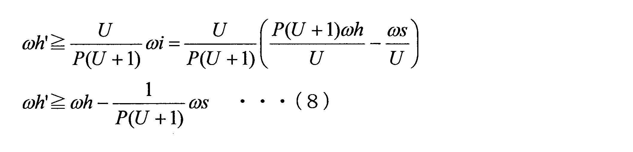
この式(6)を満足するための可変速電動機71の回転数の指令値をωh’とすると、指令値ωh’は、以下の式(7)を満たす必要があることがわかる。
(1+U)×P×ωh-U×ωi≧0 ・・・(6)
この式(6)を満足するための可変速電動機71の回転数の指令値をωh’とすると、指令値ωh’は、以下の式(7)を満たす必要があることがわかる。

式(7)に式(5)代入してωiを消去すると、以下の式(8)が導き出される。
同様に、式(3)、及び式(5)より、定速電動機51の回転数ωiを正回転に保つための可変速電動機71の回転数の指令値をωh’とすると、指令値ωh’は、以下の式(9)を満たす必要があることがわかる。

式(8)及び式(9)より、出力軸Ao及び定速電動機51の回転数を正回転に保つための可変速電動機71の回転数の指令値をωh’は、以下の式(10)を満たす必要があることがわかる。

次に、本実施形態の可変速増速機1の制御方法について説明する。
本実施形態の可変速増速機1の制御方法は、出力軸Aoの回転数ωs、及び可変速電動機71の回転数ωhを監視する回転数監視工程S1と、出力軸Aoの回転数ωsがωs<0を満たすか否かを判定する第一判定工程S2と、第一判定工程S2の条件を満たす場合に、可変速電動機71の回転数の指令値ωh’を設定する第一可変速電動機制御工程S3と、出力軸Aoの回転数ωs、及び可変速電動機71の回転数ωhがωs/P/(1+U)<ωhを満たすか否かを判定する第二判定工程S4と、第二判定工程S4の条件を満たす場合に、可変速電動機71の回転数の指令値ωh’を設定する第二可変速電動機制御工程S5と、を有している。
本実施形態の可変速増速機1の制御方法は、出力軸Aoの回転数ωs、及び可変速電動機71の回転数ωhを監視する回転数監視工程S1と、出力軸Aoの回転数ωsがωs<0を満たすか否かを判定する第一判定工程S2と、第一判定工程S2の条件を満たす場合に、可変速電動機71の回転数の指令値ωh’を設定する第一可変速電動機制御工程S3と、出力軸Aoの回転数ωs、及び可変速電動機71の回転数ωhがωs/P/(1+U)<ωhを満たすか否かを判定する第二判定工程S4と、第二判定工程S4の条件を満たす場合に、可変速電動機71の回転数の指令値ωh’を設定する第二可変速電動機制御工程S5と、を有している。
回転数監視工程S1では、制御部120は、出力軸Aoの回転数ωs、及び可変速電動機71の回転数ωhを監視する。
第一判定工程S2では、制御部120は、出力軸Aoの回転数ωsがωs<0を満たすか否かを判定する。即ち、出力軸Aoが逆回転していないかを判定する。出力軸Aoが逆回転している場合は、第一可変速電動機制御工程S3に移行する。
第一判定工程S2では、制御部120は、出力軸Aoの回転数ωsがωs<0を満たすか否かを判定する。即ち、出力軸Aoが逆回転していないかを判定する。出力軸Aoが逆回転している場合は、第一可変速電動機制御工程S3に移行する。
第一可変速電動機制御工程S3では、制御部120は、可変速電動機71の回転数の指令値ωh’をωh’=ωh-ωs/P/(1+U)に設定し、この指令値ωh’で可変速電動機71を回転させる。これにより、出力軸Aoの回転数が修正されて、出力軸Aoが逆回転しなくなる。
第二判定工程S4では、制御部120は、出力軸Aoの回転数ωs、及び可変速電動機71の回転数ωhがωs/P/(1+U)<ωhを満たすか否かを判定する。ωs/P/(1+U)<ωhを満たす場合は、第二可変速電動機制御工程S5に移行する。
第二可変速電動機制御工程S5では、制御部120は、ωh’=ωs/P/(1+U)に設定し、この指令値ωh’で可変速電動機71を回転させる。これにより、出力軸Aoの回転数が修正されて、定速電動機51の定速ロータ52が逆回転しなくなる。
上記実施形態によれば、出力軸Aoの回転数ωs、及び可変速電動機71の回転数ωhを監視して、可変速電動機71の回転数を制御することによって、出力軸Aoが逆回転するのを防止することができる。また、定速電動機51が逆回転するのを防止することができる。
また、本実施形態では、軸挿通孔74が形成された円筒状の軸である可変速ロータ軸73に棒状の軸である内歯車キャリア軸37が挿通されている。即ち、出力の大きな定速入力軸Acが定速電動機51よりも出力の小さい可変速電動機71の可変速ロータ軸73に挿通されている。これにより、定速電動機51としてより大きな出力(馬力)のあるものを採用することができる。
また、本実施形態では、定速電動機51、可変速電動機71、変速装置、圧縮機Cの順に直線状に配置していることにより、装置全体をよりコンパクトにすることができる。
また、本実施形態では、定速電動機51、可変速電動機71、変速装置、圧縮機Cの順に直線状に配置していることにより、装置全体をよりコンパクトにすることができる。
なお、上記実施形態では、制御部120は、出力軸回転数センサ131によって計測された出力軸Aoの回転数ωs、及び可変速電動機回転数センサ133によって計測された可変速電動機71の回転数ωhを用いて制御を行ったがこれに限ることはない。
例えば、出力軸Aoの回転数ωsを測定することなく、可変速電動機71の回転数ωh、及び定速電動機51の回転数ωiの測定値を用いて、出力軸Aoの回転数ωsを算出してもよい。
可変速電動機71の回転数ωh、及び定速電動機51の回転数ωiを用いて出力軸Aoの回転数ωsを算出する場合は、式(4)を用いることができる。
例えば、出力軸Aoの回転数ωsを測定することなく、可変速電動機71の回転数ωh、及び定速電動機51の回転数ωiの測定値を用いて、出力軸Aoの回転数ωsを算出してもよい。
可変速電動機71の回転数ωh、及び定速電動機51の回転数ωiを用いて出力軸Aoの回転数ωsを算出する場合は、式(4)を用いることができる。
また、上記実施形態では、可変速ロータ軸73が円筒状に形成されて、可変速ロータ軸73の軸挿通孔74に内歯車キャリア軸37が挿通される構成としたがこれに限ることはなく、例えば、可変速電動機71の可変速ロータ72の中心軸を軸線Arに対してオフセットさせてもよい。
また、上記実施形態では、圧縮機Cを高速回転させるために好適な定速電動機51として、4極の三相誘導電動機を例示し、圧縮機Cの回転数を一定の範囲内で可変速させるために好適な可変速電動機71として、6極の三相誘導電動機を例示している。しかしながら、駆動対象を高速回転させる必要がない場合には、定速電動機51や可変速電動機71として他のタイプの電動機を用いてもよい。
1 可変速増速機
10 変速装置
11 太陽歯車
12 太陽歯車軸
15 遊星歯車
17 内歯車
21 遊星歯車キャリア
22 遊星歯車軸
27 遊星歯車キャリア軸
27i 入力側遊星歯車キャリア軸
27o 出力側遊星歯車キャリア軸
31 内歯車キャリア
37 内歯車キャリア軸
41 変速ケーシング
42 太陽歯車軸受
50 電動装置
51 定速電動機
52 定速ロータ
53 定速ロータ軸
56 導体
61 定速電動機ケーシング
66 定速ステータ
71 可変速電動機
72 可変速ロータ
73 可変速ロータ軸
74 軸挿通孔
76 導体
81 可変速電動機ケーシング
86 可変速ステータ
100 回転数制御装置
101 周波数変換部
102 回転方向変更部
110 電源線
111 可変速電動機スイッチ
112 定速電動機スイッチ
120 制御部(制御装置)
121 受付部
122 インタフェース
123 演算部
Ac 定速入力軸
Ao 出力軸
Ar 軸線
Av 可変速入力軸
C 圧縮機
R1 第一方向
R2 第二方向
10 変速装置
11 太陽歯車
12 太陽歯車軸
15 遊星歯車
17 内歯車
21 遊星歯車キャリア
22 遊星歯車軸
27 遊星歯車キャリア軸
27i 入力側遊星歯車キャリア軸
27o 出力側遊星歯車キャリア軸
31 内歯車キャリア
37 内歯車キャリア軸
41 変速ケーシング
42 太陽歯車軸受
50 電動装置
51 定速電動機
52 定速ロータ
53 定速ロータ軸
56 導体
61 定速電動機ケーシング
66 定速ステータ
71 可変速電動機
72 可変速ロータ
73 可変速ロータ軸
74 軸挿通孔
76 導体
81 可変速電動機ケーシング
86 可変速ステータ
100 回転数制御装置
101 周波数変換部
102 回転方向変更部
110 電源線
111 可変速電動機スイッチ
112 定速電動機スイッチ
120 制御部(制御装置)
121 受付部
122 インタフェース
123 演算部
Ac 定速入力軸
Ao 出力軸
Ar 軸線
Av 可変速入力軸
C 圧縮機
R1 第一方向
R2 第二方向
Claims (3)
- 回転駆動力を発生する電動装置と、
前記電動装置で発生した回転駆動力を変速させて駆動対象に伝える変速装置と、
を備え、
前記変速装置は、
軸線を中心として自転する太陽歯車と、
前記太陽歯車に固定され、前記軸線を中心として、軸方向に延びる太陽歯車軸と、
前記太陽歯車と噛み合い、前記軸線を中心として公転すると共に自身の中心線を中心として自転する遊星歯車と、
前記軸線を中心として環状に複数の歯が並び、前記遊星歯車と噛み合う内歯車と、
前記軸線を中心として軸方向に延びる遊星歯車キャリア軸を有し、前記遊星歯車を、前記軸線を中心として公転可能に且つ前記遊星歯車自身の中心線を中心として自転可能に支持する遊星歯車キャリアと、
前記軸線を中心として軸方向に延びる内歯車キャリア軸を有し、前記内歯車を、前記軸線を中心として自転可能に支持する内歯車キャリアと、
を有し、
前記太陽歯車軸が前記駆動対象に接続される出力軸を成し、前記内歯車キャリア軸が定速入力軸を成し、前記遊星歯車キャリア軸が可変速入力軸を成し、
前記電動装置は、
前記変速装置の前記定速入力軸を第二方向に回転させる定速ロータを有する定速電動機と、
前記変速装置の前記可変速入力軸に接続されている可変速ロータを有し、前記可変速ロータを前記第二方向とは反対方向の第一方向に最大回転数で回転させることで、前記出力軸を最大回転数で回転させる可変速電動機と、を有し、
前記出力軸の回転数ωsを計測する出力軸回転数センサと、
前記可変速電動機の回転数ωhを計測する可変速電動機回転数センサと、
前記定速電動機の回転数ωiを計測する定速電動機回転数センサと、のうち少なくとも2つの回転数センサと、
前記回転数センサの計測値から、前記出力軸の回転数ωs及び前記可変速電動機の回転数ωhを算出する制御装置と、を備え、
前記出力軸の回転数ωsと前記定速電動機の回転数ωiの比ωs/ωiをU、
前記遊星歯車キャリアの回転数ωcと前記可変速電動機の回転数ωhの比ωc/ωhをPとすると、
前記制御装置は、ωs<0である場合に、
前記可変速電動機の回転数の指令値ωh’を、ωh’=ωh-ωs/P/(1+U)となるように算出し、前記指令値ωh’にて前記可変速電動機を制御する可変速増速機。 - 前記制御装置は、ωs/P/(1+U)<ωhである場合に、
前記可変速電動機の回転数の指令値ωh’を、ωh’=ωs/P/(1+U)となるように算出し、前記指令値ωh’にて前記可変速電動機を制御する請求項1に記載の可変速増速機。 - 前記可変速ロータは、前記軸線を中心として円筒状をなし、軸方向に貫通した軸挿通孔に前記定速入力軸が挿通されている請求項1又は請求項2に記載の可変速増速機。
Priority Applications (5)
| Application Number | Priority Date | Filing Date | Title |
|---|---|---|---|
| PCT/JP2016/065020 WO2017199428A1 (ja) | 2016-05-20 | 2016-05-20 | 可変速増速機 |
| EP17799523.0A EP3419147B1 (en) | 2016-05-20 | 2017-05-19 | Variable speed accelerator |
| PCT/JP2017/018907 WO2017200099A1 (ja) | 2016-05-20 | 2017-05-19 | 可変速増速機 |
| US16/086,217 US10837526B2 (en) | 2016-05-20 | 2017-05-19 | Variable-speed speed-up mechanism |
| JP2018518393A JP6590174B2 (ja) | 2016-05-20 | 2017-05-19 | 可変速増速機 |
Applications Claiming Priority (1)
| Application Number | Priority Date | Filing Date | Title |
|---|---|---|---|
| PCT/JP2016/065020 WO2017199428A1 (ja) | 2016-05-20 | 2016-05-20 | 可変速増速機 |
Publications (1)
| Publication Number | Publication Date |
|---|---|
| WO2017199428A1 true WO2017199428A1 (ja) | 2017-11-23 |
Family
ID=60324903
Family Applications (2)
| Application Number | Title | Priority Date | Filing Date |
|---|---|---|---|
| PCT/JP2016/065020 Ceased WO2017199428A1 (ja) | 2016-05-20 | 2016-05-20 | 可変速増速機 |
| PCT/JP2017/018907 Ceased WO2017200099A1 (ja) | 2016-05-20 | 2017-05-19 | 可変速増速機 |
Family Applications After (1)
| Application Number | Title | Priority Date | Filing Date |
|---|---|---|---|
| PCT/JP2017/018907 Ceased WO2017200099A1 (ja) | 2016-05-20 | 2017-05-19 | 可変速増速機 |
Country Status (4)
| Country | Link |
|---|---|
| US (1) | US10837526B2 (ja) |
| EP (1) | EP3419147B1 (ja) |
| JP (1) | JP6590174B2 (ja) |
| WO (2) | WO2017199428A1 (ja) |
Families Citing this family (1)
| Publication number | Priority date | Publication date | Assignee | Title |
|---|---|---|---|---|
| CN120140430B (zh) * | 2025-02-05 | 2025-11-18 | 中国航空发动机研究院 | 一种可实现无级变速的航空发动机行星齿轮传动系统 |
Citations (1)
| Publication number | Priority date | Publication date | Assignee | Title |
|---|---|---|---|---|
| WO2016010146A1 (ja) * | 2014-07-18 | 2016-01-21 | 三菱重工コンプレッサ株式会社 | 可変電動機システム、及び電動装置 |
Family Cites Families (11)
| Publication number | Priority date | Publication date | Assignee | Title |
|---|---|---|---|---|
| JPS5970497A (ja) | 1982-10-14 | 1984-04-20 | Aida Eng Ltd | プレス変速駆動装置 |
| US4514991A (en) | 1983-10-17 | 1985-05-07 | Carrier Corporation | Variable speed drive motor system with inverter control |
| JP4472350B2 (ja) | 2002-02-21 | 2010-06-02 | 株式会社荏原製作所 | 差動遊星歯車装置の始動装置 |
| JP4183481B2 (ja) | 2002-11-01 | 2008-11-19 | 有限会社クチダギアリング | 変速装置 |
| JP4943699B2 (ja) * | 2005-03-02 | 2012-05-30 | 株式会社神戸製鋼所 | 混練機および混練制御方法 |
| JP2010242811A (ja) | 2009-04-02 | 2010-10-28 | Kuchida Gearing:Kk | 変速装置 |
| DE102014115191B4 (de) * | 2014-10-14 | 2019-04-25 | Andreas Basteck | Vorrichtung und Verfahren zum Antrieb von drehzahlvariablen Arbeitsmaschinen |
| JP6566285B2 (ja) * | 2016-06-15 | 2019-08-28 | 三菱重工コンプレッサ株式会社 | 可変速増速機、及び可変速増速機の制御方法 |
| DE112016006978B4 (de) * | 2016-06-15 | 2022-05-25 | Mitsubishi Heavy Industries Compressor Corporation | Beschleuniger variabler Geschwindigkeit mit zwei Motoren und Überlagerungsgetriebe |
| WO2017216888A1 (ja) * | 2016-06-15 | 2017-12-21 | 三菱重工コンプレッサ株式会社 | 可変速増速機及び可変速増速機の始動方法 |
| US9664261B1 (en) * | 2016-06-22 | 2017-05-30 | Schaeffler Technologies AG & Co. KG | Planetary differential CVT with anti-freewheel one way clutch |
-
2016
- 2016-05-20 WO PCT/JP2016/065020 patent/WO2017199428A1/ja not_active Ceased
-
2017
- 2017-05-19 EP EP17799523.0A patent/EP3419147B1/en active Active
- 2017-05-19 WO PCT/JP2017/018907 patent/WO2017200099A1/ja not_active Ceased
- 2017-05-19 US US16/086,217 patent/US10837526B2/en active Active
- 2017-05-19 JP JP2018518393A patent/JP6590174B2/ja active Active
Patent Citations (1)
| Publication number | Priority date | Publication date | Assignee | Title |
|---|---|---|---|---|
| WO2016010146A1 (ja) * | 2014-07-18 | 2016-01-21 | 三菱重工コンプレッサ株式会社 | 可変電動機システム、及び電動装置 |
Also Published As
| Publication number | Publication date |
|---|---|
| US20200292033A1 (en) | 2020-09-17 |
| EP3419147A4 (en) | 2019-02-27 |
| EP3419147B1 (en) | 2020-04-01 |
| EP3419147A1 (en) | 2018-12-26 |
| WO2017200099A1 (ja) | 2017-11-23 |
| US10837526B2 (en) | 2020-11-17 |
| JP6590174B2 (ja) | 2019-10-16 |
| JPWO2017200099A1 (ja) | 2019-02-14 |
Similar Documents
| Publication | Publication Date | Title |
|---|---|---|
| JP6566285B2 (ja) | 可変速増速機、及び可変速増速機の制御方法 | |
| JP6508853B2 (ja) | 可変速増速機の始動方法及び可変速増速機の始動制御装置 | |
| JP6627184B2 (ja) | 可変速増速機 | |
| JP6489628B2 (ja) | 可変速電動機システムの制御方法及び可変速電動機システムの制御装置 | |
| JP6676164B2 (ja) | 可変速増速機及び可変速増速機の始動方法 | |
| JP6582350B2 (ja) | 可変速増速機の始動方法及び可変速増速機の始動制御装置 | |
| US10680539B2 (en) | Variable-speed speed increaser | |
| JPWO2018016097A1 (ja) | 可変速増速機、可変速増速機の制御装置、及び可変速増速機の制御方法 | |
| JP6548101B2 (ja) | 可変速増速機 | |
| WO2017145377A1 (ja) | 可変速増速機及び可変速増速機の制御方法 | |
| JPWO2017195321A1 (ja) | 可変速増速機 | |
| JP6590174B2 (ja) | 可変速増速機 | |
| JP6777741B2 (ja) | 変速装置の設計方法、変速装置の製造方法、及び可変速増速機の製造方法 | |
| WO2017145367A1 (ja) | 可変速増速機 | |
| WO2018042485A1 (ja) | 可変速増速機 |
Legal Events
| Date | Code | Title | Description |
|---|---|---|---|
| NENP | Non-entry into the national phase |
Ref country code: DE |
|
| 121 | Ep: the epo has been informed by wipo that ep was designated in this application |
Ref document number: 16902447 Country of ref document: EP Kind code of ref document: A1 |
|
| 122 | Ep: pct application non-entry in european phase |
Ref document number: 16902447 Country of ref document: EP Kind code of ref document: A1 |
|
| NENP | Non-entry into the national phase |
Ref country code: JP |