WO2017199438A1 - 圧縮機、圧縮機の製造方法、及び拡管器具 - Google Patents
圧縮機、圧縮機の製造方法、及び拡管器具 Download PDFInfo
- Publication number
- WO2017199438A1 WO2017199438A1 PCT/JP2016/065058 JP2016065058W WO2017199438A1 WO 2017199438 A1 WO2017199438 A1 WO 2017199438A1 JP 2016065058 W JP2016065058 W JP 2016065058W WO 2017199438 A1 WO2017199438 A1 WO 2017199438A1
- Authority
- WO
- WIPO (PCT)
- Prior art keywords
- compressor
- tube expansion
- sealed container
- compression mechanism
- pressure
- Prior art date
- Legal status (The legal status is an assumption and is not a legal conclusion. Google has not performed a legal analysis and makes no representation as to the accuracy of the status listed.)
- Ceased
Links
Images


Classifications
-
- B—PERFORMING OPERATIONS; TRANSPORTING
- B21—MECHANICAL METAL-WORKING WITHOUT ESSENTIALLY REMOVING MATERIAL; PUNCHING METAL
- B21D—WORKING OR PROCESSING OF SHEET METAL OR METAL TUBES, RODS OR PROFILES WITHOUT ESSENTIALLY REMOVING MATERIAL; PUNCHING METAL
- B21D39/00—Application of procedures in order to connect objects or parts, e.g. coating with sheet metal otherwise than by plating; Tube expanders
- B21D39/08—Tube expanders
- B21D39/20—Tube expanders with mandrels, e.g. expandable
-
- B—PERFORMING OPERATIONS; TRANSPORTING
- B21—MECHANICAL METAL-WORKING WITHOUT ESSENTIALLY REMOVING MATERIAL; PUNCHING METAL
- B21D—WORKING OR PROCESSING OF SHEET METAL OR METAL TUBES, RODS OR PROFILES WITHOUT ESSENTIALLY REMOVING MATERIAL; PUNCHING METAL
- B21D51/00—Making hollow objects
- B21D51/16—Making hollow objects characterised by the use of the objects
- B21D51/38—Making inlet or outlet arrangements of cans, tins, baths, bottles, or other vessels; Making can ends; Making closures
- B21D51/44—Making closures, e.g. caps
- B21D51/46—Placing sealings or sealing material
-
- F—MECHANICAL ENGINEERING; LIGHTING; HEATING; WEAPONS; BLASTING
- F04—POSITIVE - DISPLACEMENT MACHINES FOR LIQUIDS; PUMPS FOR LIQUIDS OR ELASTIC FLUIDS
- F04B—POSITIVE-DISPLACEMENT MACHINES FOR LIQUIDS; PUMPS
- F04B39/00—Component parts, details, or accessories, of pumps or pumping systems specially adapted for elastic fluids, not otherwise provided for in, or of interest apart from, groups F04B25/00 - F04B37/00
- F04B39/12—Casings; Cylinders; Cylinder heads; Fluid connections
-
- F—MECHANICAL ENGINEERING; LIGHTING; HEATING; WEAPONS; BLASTING
- F04—POSITIVE - DISPLACEMENT MACHINES FOR LIQUIDS; PUMPS FOR LIQUIDS OR ELASTIC FLUIDS
- F04C—ROTARY-PISTON, OR OSCILLATING-PISTON, POSITIVE-DISPLACEMENT MACHINES FOR LIQUIDS; ROTARY-PISTON, OR OSCILLATING-PISTON, POSITIVE-DISPLACEMENT PUMPS
- F04C29/00—Component parts, details or accessories of pumps or pumping installations, not provided for in groups F04C18/00 - F04C28/00
Definitions
- the present invention relates to a compressor including a pressure-sealed container in which a body part, a bottom part, and a lid part are joined by welding, a manufacturing method of the compressor, and a tube expanding device used for manufacturing the pressure-sealed container.
- Patent Document 1 As a conventional compressor including a pressure-sealed container in which a body part, a bottom part, and a lid part are joined by welding, for example, in Patent Document 1, a cylindrical case and a lid body are fitted together, and a contact portion is sealed by welding. What is provided with a closed sealed container is disclosed.
- a cylindrical case if the welded part is harder than other parts, if the cylindrical case is expanded, the inner diameter of the cylindrical case is not uniform, and the cylindrical case is welded. A portion adjacent to the portion may be tapered.
- the compression mechanism portion is arranged in the tapered cylindrical case portion, the gap between the side surface portion of the compression mechanism portion and the inner side surface of the cylindrical case is not constant. It may be fixed to the closed container in a distorted state. Therefore, in the compressor of patent document 1, when the compression mechanism part was fixed to the airtight container in the distorted state, the performance of the compressor fell and there existed a subject that the reliability of a compressor could not be ensured.
- the present invention solves the above-described problem, and a compressor capable of avoiding a decrease in performance and ensuring reliability due to being fixed to a pressure-sealed container in a state where the compression mechanism section is distorted, and the compression It aims at providing the manufacturing method of a machine, and the pipe expansion apparatus which can manufacture this pressure sealed container.
- a compressor according to the present invention includes a compression mechanism portion that compresses a refrigerant, a crankshaft that transmits a rotational driving force to the compression mechanism portion, an electric motor portion that generates the rotational driving force on the crankshaft, and a cylindrical body. Part, a bottom part joined to one end of the body part, and a lid part joined to the other end of the body part, containing the compression mechanism part, the crankshaft, and the electric motor part,
- the body portion includes a pressure sealed container to which the compression mechanism portion and the electric motor portion are fixed, and the first body expansion is performed before the bottom portion is joined to the body portion.
- An inner surface, a second inner surface having a smaller inner diameter than the first inner surface, and a third inner surface extending between the first inner surface and the second inner surface are formed, and the body portion Second pipe expansion performed after the bottom is joined to The shape, the second inner surface and the third inner surface is tube expansion to the inside diameter of the first inner surface.
- the compressor manufacturing method includes a cylindrical body part, a bottom part joined to one end of the body part, and a pressure sealed having a lid part joined to the other end of the body part.
- a method of manufacturing a compressor including a container, wherein the first inner surface, a second inner surface having a smaller inner diameter than the first inner surface, and the first before the bottom portion is joined to the body portion.
- the tube expansion device is a tube expansion device for manufacturing a pressure sealed container of a compressor, and includes a cylindrical first outer surface portion and a first outer surface portion having a smaller radius on the circumferential surface than the first outer surface portion.
- a tube expansion mold portion having two outer surface portions, a third outer surface portion extending between the first outer surface portion and the second outer surface portion, a casing portion supporting the tube expansion mold portion, and the tube expansion
- a rod portion reciprocally disposed within the mold portion and the casing portion, the tube expansion mold portion being disposed adjacent to a circumferential direction of the tube expansion mold portion, and movement of the rod portion
- a plurality of split molds that move in the circumferential surface direction of the tube expansion mold part are provided, and each of the split molds includes a first curved surface part having an arcuate surface shape that constitutes the first outer surface part.
- a second curved surface portion having an arcuate surface shape constituting the second outer surface portion, and the third outer surface. Part constitute, and a connecting surface portion extending between said
- the present invention by performing the first tube expansion molding and the second tube expansion molding, it is possible to avoid fixing the compression mechanism portion to the pressure sealed container in a distorted state. Therefore, according to the present invention, a compressor capable of avoiding deterioration in performance and securing reliability due to being fixed to the pressure sealed container in a state where the compression mechanism portion is distorted, and a method for manufacturing the compressor, A tube expansion device for manufacturing the pressure-sealed container can be provided.
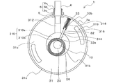
- FIG. 2 is a schematic diagram of an AA cross section of FIG. 1 showing an example of an internal structure of a compression mechanism section 30 of the compressor 1 according to Embodiment 1 of the present invention.
- FIG. 1 In the manufacturing process of the compressor 1 of Embodiment 1 of this invention, it is a perspective view which shows roughly the external appearance of the steel plate 50 before shaping
- FIG. It is the schematic which shows the structure of the steel plate 50 before winding forming, and the one part structure of the roll apparatus 100 in the manufacturing process of the compressor 1 of Embodiment 1 of this invention.
- FIG. 1 shows another modification of the external appearance structure of the 1st pipe expansion apparatus 130 of the 1st pipe expansion apparatus 200a used by 1st pipe expansion molding. It is the schematic which shows the internal structure of the 1st tube expansion instrument 130 of FIG. Schematic showing the cross-sectional structure of the body portion 2a of the pressure-sealed container 2 and the partial cross-sectional structure of the first tube expansion device 200a before the first tube expansion molding in the manufacturing process of the compressor 1 according to Embodiment 1 of the present invention.
- FIG. 1 It is sectional drawing which shows roughly the structure of the trunk
- FIG. It is the schematic which shows the internal structure of the 2nd tube expansion instrument 170 of FIG.
- the cross-sectional structure of the body portion 2a and the bottom portion 2b of the pressure-sealed container 2 and the partial cross-sectional structure of the second tube expansion device 200b before the second tube expansion molding is performed.
- FIG. 1 The width of the distortion of the body portion 2a of the pressure sealed container 2 after the second tube expansion molding in the manufacturing process of the conventional compressor 1 and the second tube expansion molding in the manufacturing process of the compressor 1 according to the first embodiment of the present invention. It is the graph which compared the width
- FIG. 1 is a longitudinal sectional view schematically showing an example of a compressor 1 according to the first embodiment.
- the compressor 1 is used in a refrigeration cycle apparatus such as an air conditioner, and is an element constituting a refrigerant circuit of the refrigeration cycle apparatus.
- the refrigerant circuit and other components constituting the refrigerant circuit such as a radiator, an evaporator, a decompression device, and an oil separator are not illustrated.
- the dimensional relationship and shape of each component may be different from the actual one.
- symbol is attached
- the positional relationship between the constituent members of the compressor 1 for example, the positional relationship such as the vertical relationship, is basically the positional relationship when the compressor 1 is installed in a usable state.
- the compressor 1 is a rolling piston type rotary compressor, and is a fluid machine that discharges a low-pressure gas refrigerant sucked into the compressor 1 as a high-pressure gas refrigerant.
- the casing of the compressor 1 is configured as a cylinder-shaped pressure sealed container 2.
- the pressure sealed container 2 includes a hollow cylindrical body portion 2a, a bottom portion 2b having a U-shaped longitudinal section, and a lid portion 2c having an inverted U-shaped longitudinal section, and an opening of the bottom portion 2b and the lid portion 2c.
- the outer side surface of the part is fixed to the inner side surface of the opening of the body part 2a.
- the fixed portion with the bottom portion 2b and the fixed portion with the lid portion 2c of the body portion 2a are joined by, for example, arc welding or resistance welding.
- the housing 3a of the suction muffler 3 is disposed outside the body portion 2a of the pressure sealed container 2.
- the housing 3 a of the suction muffler 3 is fixed to the body portion 2 a of the pressure sealed container 2 through a support member disposed on the outer surface of the pressure sealed container 2.
- An inflow pipe 3b is fixed to the top of the housing 3a of the suction muffler 3 through the housing 3a.
- the inflow pipe 3 b is a refrigerant pipe through which a low-pressure gas refrigerant or a two-phase refrigerant having a high degree of dryness flows into the housing 3 a of the suction muffler 3.
- one end of the suction pipe 4 passes through and is fixed to the bottom of the housing 3 a of the suction muffler 3, and the other end of the suction pipe 4 passes through the side surface of the body portion 2 a of the pressure sealed container 2. And fixed.
- the suction muffler 3 is a silencer that reduces or eliminates noise generated by the refrigerant flowing from the inflow pipe 3b.
- the suction muffler 3 also has an accumulator function, and has a refrigerant storage function for storing surplus refrigerant and a gas-liquid separation function for retaining liquid refrigerant that is temporarily generated when the operating state changes. Have. Due to the gas-liquid separation function of the suction muffler 3, it is possible to prevent a large amount of liquid refrigerant from flowing into the pressure sealed container 2 and performing liquid compression in the compressor 1.
- the suction pipe 4 is a refrigerant pipe for sucking low-pressure gas refrigerant from the suction muffler 3 into the pressure sealed container 2.
- a fixing member 6 is disposed in the suction hole 5 provided in the body portion 2 a of the pressure sealed container 2, and the suction pipe 4 is connected to the pressure sealed container 2 via the fixing member 6 disposed in the suction hole 5.
- the body part 2a is fixed.
- the suction pipe 4 is provided with an oil return hole in the side surface portion, and the lubricating oil component contained in the high-pressure gas refrigerant separated in the oil separator of the refrigeration cycle apparatus. May be returned to the inside through the suction pipe 4.
- the fixing member 6 can be configured to include, for example, an extension pipe 6a, a connection pipe 6b, and a ring 6c.
- the extension pipe 6 a is inserted into the suction hole 5 and communicates with the inside of the pressure sealed container 2.
- the suction pipe 4 is inserted into the extension pipe 6a.
- the connecting pipe 6b is joined to the outer surface of the extension pipe 6a, and seals the gap between the outer surface of the suction pipe 4 and the inner side surface of the extension pipe 6a.
- the ring 6 c is joined to the suction hole 5, joined to the outer surfaces of the extension pipe 6 a and the connection pipe 6 b and the pressure sealed container 2, and seals a gap between the suction pipe 4 and the suction hole 5.
- the fixing member 6 ensures airtightness inside the pressure sealed container 2.
- the discharge pipe 7 is fixed through the upper surface of the lid portion 2c of the pressure sealed container 2.
- the discharge pipe 7 is a refrigerant pipe that discharges a high-pressure gas refrigerant to the outside of the pressure sealed container 2.
- the fixed portion between the discharge pipe 7 and the lid portion 2c is joined, for example, by brazing or resistance welding.
- a glass terminal 8 is disposed on the upper surface of the lid 2c of the pressure sealed container 2.
- the glass terminal 8 provides an interface for connecting an external power source.
- the external power supply is a power supply device that supplies power to the compressor 1, and a general commercial AC power supply having an AC frequency of 50 Hz or 60 Hz, or an inverter power supply capable of changing the AC frequency is used.
- the frequency variable inverter power supply is used, the rotation speed of the compressor 1 can be changed, so that the compressor 1 can control the discharge amount of the high-pressure gas refrigerant from the discharge pipe 7.
- the external power source connected to the glass terminal 8 is not shown in the following drawings including FIG.
- an electric motor unit 10 In the pressure sealed container 2, an electric motor unit 10, a crankshaft 20, and a compression mechanism unit 30 are accommodated.
- the electric motor unit 10 is arranged above the arrangement position of the fixing member 6 in the pressure sealed container 2.
- the crankshaft 20 is disposed between the electric motor unit 10 and the compression mechanism unit 30 at the center of the pressure sealed container 2, and extends between the electric motor unit 10 and the compression mechanism unit 30 in the vertical direction.
- the compression mechanism unit 30 is arranged so that the inside of the compression mechanism unit 30 communicates with the suction pipe 4. That is, the electric motor unit 10 is disposed above the compression mechanism unit 30 inside the pressure sealed container 2.
- the hollow space inside the pressure sealed container 2 is filled with a high-pressure gas refrigerant compressed by the compression mechanism unit 30.
- the electric motor unit 10 is configured as a motor that generates a rotational driving force on the crankshaft 20 using electric power supplied from an external power source and transmits the rotational driving force to the compression mechanism unit 30 via the crankshaft 20.
- the electric motor unit 10 includes a stator 12 having a hollow cylindrical appearance in a top view, and a cylindrical rotor 14 that is rotatably disposed inside the inner surface of the stator 12.
- the stator 12 is fixed to the inner side surface of the body portion 2 a of the pressure sealed container 2 by shrink fitting or the like, and is connected to the glass terminal 8 through a conducting wire 16.
- the electric motor unit 10 can rotate the rotor 14 inside the inner surface of the stator 12 by supplying electric power from an external power source to the coil wound around the stator 12 via the conductive wire 16.
- a DC brushless motor or the like is used as the electric motor unit 10.
- a crankshaft 20 is fixed through the rotor 14 at the center of the rotor 14.
- the crankshaft 20 is a rotating shaft that fixes the rotor 14 with a fixed surface 20 a that is a part of the outer surface of the crankshaft 20 and transmits the rotational driving force of the rotor 14 to the compression mechanism 30.
- the crankshaft 20 extends from the fixed surface 20 a in the vertical direction, that is, in the direction of the lid portion 2 c of the pressure sealed container 2 and the direction of the bottom portion 2 b of the pressure sealed container 2.
- crankshaft 20 has a cylindrical eccentric portion 24 that is located below the fixed surface 20 a and is disposed inside the compression mechanism portion 30.
- a piston 26 attached rotatably along the outer side surface of the eccentric part 24 is disposed.
- a refrigerating machine oil 40 that extends upward from the lower end of the crankshaft 20 and is sucked up from the lower end of the crankshaft 20 at the center of the crankshaft 20.
- An oil hole through which the lubricating oil is flowing is provided.
- a plurality of oil supply ports that communicate with the above-described oil holes and supply lubricating oil to the compression mechanism 30 are provided on the outer surface of the crankshaft 20.
- a centrifugal pump can be arranged at the lower end of the oil hole of the crankshaft 20.
- the above-described centrifugal pump is configured as, for example, a spiral centrifugal pump so that the refrigerating machine oil 40 stored at the bottom of the bottom 2b of the pressure sealed container 2 can be sucked up.
- the refrigerating machine oil 40 for example, mineral oil-based, alkylbenzene-based, polyalkylene glycol-based, polyvinyl ether-based, polyol ester-based lubricating oil, or the like is used.
- FIG. 2 is a schematic diagram of an AA cross section of FIG. 1 showing an example of the internal structure of the compression mechanism unit 30 of the compressor 1 according to the first embodiment.
- the compression mechanism unit 30 compresses the low-pressure gas refrigerant sucked into the low-pressure space of the pressure sealed container 2 from the suction pipe 4 into the high-pressure gas refrigerant by the rotational driving force supplied from the electric motor unit 10, and compresses the compressed high-pressure gas refrigerant.
- a gas refrigerant is discharged above the compression mechanism 30.
- the compression mechanism portion 30 extends between a pair of hollow disk surfaces 31a, an inner side surface 31b extending between the inner edge portions of the pair of hollow disk surfaces 31a, and an outer edge portion of the pair of hollow disk surfaces 31a.
- a hollow cylindrical cylinder 31 having an outer side surface 31c is provided.
- the outer surface 31c of the cylinder 31 is fixed to the inner surface of the body portion 2a of the pressure sealed container 2 by arc welding such as arc spot welding or shrink fitting.
- the hollow portion 310 of the cylinder 31 is formed in a space surrounded by the inner surface 31b of the cylinder 31, and accommodates the eccentric portion 24 and the piston 26 of the crankshaft 20. That is, the cylinder 31 is configured so that the eccentric portion 24 of the crankshaft 20 and the piston 26 can rotate eccentrically by the rotation of the crankshaft 20 in the hollow portion 310 of the cylinder 31.
- the cylinder 31 has a suction passage 312 that allows the suction pipe 4 and the hollow portion 310 of the cylinder 31 to communicate with each other via the connection pipe 6 b and allows low-pressure gas refrigerant to flow from the suction pipe 4 into the hollow portion 310 of the cylinder 31.
- a semicircular discharge passage 314 extending in the vertical direction is provided on the inner surface of the cylinder 31.
- the cylinder 31 is provided with a vane groove 316 extending in the radial direction from the inner side surface 31b of the cylinder 31 toward the outer side surface 31c of the cylinder 31 in a top view.
- the vane 32 is accommodated in the vane groove 316 of the cylinder 31.
- the vane 32 is a sliding member configured to reciprocate in the radial direction inside the vane groove 316 by the eccentric movement of the piston 26.
- the tip 32 a of the vane 32 disposed in the hollow portion 310 of the cylinder 31 is caused by the restoring force of the elastic body 33 such as a spring provided in the vane groove 316 or the pressure from the high-pressure portion above the compression mechanism 30.
- the piston 26 is pressed against the outer surface. As shown in FIG.
- the hollow portion 310 of the cylinder 31 has a low-pressure space portion 310 a that communicates with the suction passage 312 and a high-pressure space that communicates with the discharge passage 314 by the vane 32 and the piston 26. It is divided into a part 310b.
- the low pressure space portion 310a and the high pressure space portion 310b are spaces that constitute a compression chamber of the compression mechanism portion 30 described later.
- the low pressure space portion 310a is also referred to as a low pressure chamber
- the high pressure space portion 310b is also referred to as a high pressure chamber.
- the cylinder 31 is provided with a vane groove opening 318 that communicates with the vane groove 316 and penetrates the pair of hollow disk surfaces 31 a of the cylinder 31.
- the pressure from the high pressure portion above the compression mechanism portion 30 can be applied to the end portion 32 b of the vane 32 through the vane groove opening 318.
- the movement of the vane 32 toward the outer surface of the cylinder 31 can be restricted by the vane groove opening 318.
- the lubricating oil separated from the high-pressure gas refrigerant by the vane groove opening 318 is supplied to the clearance between the vane groove 316 and the vane 32, and the vane 32 can be smoothly reciprocated.
- the clearance between the vane groove 316 and the vane 32 is configured so that friction does not occur between the vane groove 316 and the vane 32.
- the clearance between the vane groove 316 and the vane 32 is increased, the refrigerant gas compressed in the hollow portion 310 of the cylinder 31 is transferred to the outside of the compression mechanism unit 30 via the clearance and the vane groove opening 318. Leakage may cause compression efficiency to decrease. Therefore, in the compression mechanism section 30, by reducing the clearance to such an extent that friction does not occur between the vane groove 316 and the vane 32, leakage of the compressed refrigerant gas is suppressed, leakage loss is reduced, and compression efficiency is reduced. Can be improved.
- the cylinder 31 is provided with a plurality of openings 319 that are located on the outer surface 31c side of the cylinder 31 and penetrate the pair of hollow disk surfaces 31a. Since the lubricating oil separated from the high-pressure gas refrigerant by the opening 319 and moved to the hollow disk surface 31a on the upper side of the cylinder 31 by the action of gravity can be returned to the bottom 2b of the pressure-sealed container 2, The exhaust of the machine oil 40 can be prevented.
- An upper bearing 34 is disposed on the hollow disk surface 31 a on the upper side of the cylinder 31, that is, on the hollow disk surface 31 a on the lid portion 2 c side of the pressure sealed container 2.
- a lower bearing 35 is disposed on the hollow disk surface 31 a on the lower side of the cylinder 31, that is, on the hollow disk surface 31 a on the side of the bottom 2 b of the pressure sealed container 2.
- the upper bearing 34 and the lower bearing 35 are sliding bearings that slidably support the crankshaft 20.
- the upper bearing 34 has a hollow disc shape when viewed from above.
- the upper bearing 34 has a fixed portion 34a fixed to the hollow disk surface 31a on the upper side of the cylinder 31, and a bearing portion 34b that supports the outer surface of the crankshaft 20 so as to be slidable.
- the upper bearing 34 is displayed as two L-shaped members in the longitudinal sectional view of FIG. Moreover, the upper bearing 34 is being fixed to the hollow disc surface 31a above the cylinder 31 with the volt
- the lower bearing 35 has a hollow disk shape in the bottom view.
- the lower bearing 35 includes a fixed portion 35a that is fixed to the lower hollow disk surface 31a of the cylinder 31, and a bearing portion 35b that slidably supports the outer surface of the crankshaft 20.
- the lower bearing 35 is displayed as two L-shaped members in the longitudinal sectional view of FIG. Further, the lower bearing 35 is fixed to the hollow disk surface 31a on the lower side of the cylinder 31 with, for example, a bolt or the like.
- a sealable space surrounded by the piston 26, the cylinder 31, the vane 32, the fixed portion 34 a of the upper bearing 34, and the fixed portion 35 a of the lower bearing 35 is a low pressure sucked from the suction pipe 4.
- the high-pressure gas refrigerant compressed in the compression chamber is discharged from a discharge port provided in the upper bearing 34.
- the discharge port provided in the upper bearing 34 is not shown in the following drawings including FIG.
- the compressor 1 is configured as a vertical type compressor, but may be configured as a horizontal type compressor.
- the compressor 1 is configured as a rolling piston type rotary compressor.
- the compressor 1 may be configured as a screw compressor or a scroll compressor even if configured as a swing vane type swing compressor. May be.
- the rotary compressor is configured as a single rotary type, but may be configured as a twin rotary type rotary compressor.
- the compressor 1 is a single-stage compressor and has only one compression mechanism unit 30.
- the compressor 1 is a multi-stage compressor, and a plurality of compression mechanism units 30 provide refrigerant. It is good also as a structure which compresses sequentially.
- a charge pipe can be passed through and fixed to the upper surface of the lid 2c of the pressure sealed container 2.
- the charge pipe is configured so that lubricating oil can be sealed inside the pressure sealed container 2 even if the pressure sealed container 2 can be evacuated and gas refrigerant can be sealed inside the pressure sealed container 2. May be.
- an oil separation plate is provided above the fixed surface 20a of the crankshaft 20 to separate the lubricating oil contained in the high-pressure gas refrigerant discharged from the compression mechanism 30 by the centrifugal force generated by the rotation of the crankshaft 20. Can do.
- a silencer that removes or reduces noise generated when the refrigerant is compressed in the compression mechanism 30 can be disposed on the upper surface side of the fixed portion 34a of the upper bearing 34.
- the silencer can be provided with a plurality of openings through which high-pressure gas refrigerant flowing from the discharge port provided in the upper bearing 34 is discharged into the pressure sealed container 2.
- the eccentric portion 24 and the piston 26 housed in the cylinder 31 are eccentrically rotated together with the crankshaft 20. Due to the eccentric rotation of the eccentric portion 24 and the piston 26, the outer peripheral surface of the piston 26 moves in contact with the inner side surface 31 b of the cylinder 31 in the hollow portion 310 of the cylinder 31. In conjunction with the eccentric rotation of the piston 26 of the cylinder 31, the vane 32 provided in the vane groove 316 of the cylinder 31 performs a piston motion.
- the low-pressure gas refrigerant that has flowed from the suction pipe 4 into the compression mechanism 30 via the suction passage 312 is surrounded by the piston 26, the cylinder 31, the vane 32, the fixed portion 34a of the upper bearing 34, and the fixed portion 35a of the lower bearing 35. Flows into the compression chamber, which is a sealed space.
- the low-pressure gas refrigerant flowing into the compression chamber is compressed into the high-pressure gas refrigerant as the compression chamber volume decreases due to the eccentric rotation of the piston 26.
- the high-pressure gas refrigerant is discharged into a hollow space inside the pressure sealed container 2 outside the compression mechanism portion 30 through a discharge port provided in the upper bearing 34.
- the high-pressure gas refrigerant discharged into the hollow space inside the pressure-sealed container 2 passes through, for example, the gap between the stator 12 and the rotor 14 of the electric motor unit 10 and is pressure-sealed through the discharge pipe 7. It is discharged out of the container 2.
- FIG. 3 is a perspective view schematically showing an appearance of a steel plate 50 before forming used in the manufacturing process of the body portion 2a of the pressure-sealed container 2 in the manufacturing process of the compressor 1 of the first embodiment.
- a rectangular steel plate 50 having a first plate-like surface portion 52a and a second plate-like surface portion 52b, which are a pair of rectangular plate-like surface portions 52, is used for manufacturing the body portion 2a.
- a steel material such as stainless steel or carbon steel is used.
- the body part 2a of the pressure sealed container 2 is manufactured by forming a steel plate 50.
- the body portion 2a of the pressure-sealed container 2 is manufactured by joining a first edge portion 54a and a second edge portion 54b, which are one pair of edge portions of the steel plate 50, by welding or the like.
- the body portion 2a of the pressure sealed container 2 has a plate-like surface portion 52 of the steel plate 50 formed into a cylindrical shape, and a third edge portion 56a and a fourth edge portion which are the other pair of edge portions of the steel plate 50.
- 56b is manufactured by being formed into a circumferential shape.
- FIG. 4 is a schematic diagram showing the structure of the steel plate 50 before winding and the partial structure of the roll device 100 in the manufacturing process of the compressor 1 of the first embodiment.
- a roll apparatus 100 having a first roller 100 a, a second roller 100 b, and a third roller 100 c is used in the winding forming of the steel plate 50.
- the 1st roller 100a is arrange
- the diameter of the 1st roller 100a can be comprised larger than the diameter of the 2nd roller 100b and the 3rd roller 100c.
- FIG. 5 is a schematic diagram showing the structure of the steel plate 50 and the structure of a part of the roll device 100 at the start of winding forming in the manufacturing process of the compressor 1 of the first embodiment.
- the pressing directions of the second roller 100b and the third roller 100c at the start of winding forming are indicated by arrows.
- the roll device 100 presses the second roller 100b and the third roller 100c perpendicularly to the first plate-like surface portion 52a of the steel plate 50, so that the first plate An operation of pressing the surface portion 52a toward the first roller 100a is performed.
- the steel plate 50 can be sandwiched between the first roller 100a by the pressing operation of the second roller 100b and the third roller 100c.
- FIG. 6 is a schematic diagram showing the structure of the steel sheet 50 during winding and the partial structure of the roll device 100 in the manufacturing process of the compressor 1 of the first embodiment.
- the rotation directions of the first roller 100a, the second roller 100b, and the third roller 100c during winding are indicated by arrows.
- the first roller 100a rotates in the opposite direction to the second roller 100b and the third roller 100c.
- the first roller 100a performs a counterclockwise rotation operation
- the second roller 100b and the third roller 100c perform a clockwise rotation operation.
- the steel plate 50 is moved along the first roller 100a in the rotation direction of the first roller 100a by the rotation operation of the first roller 100a, the second roller 100b, and the third roller 100c, and the winding is performed. Can be done.
- FIG. 7 is a schematic diagram showing the structure of the steel plate 50 and the structure of a part of the roll device 100 at the end of winding forming in the manufacturing process of the compressor 1 of the first embodiment.
- the steel plate 50 is wound by the rotating operation of the first roller 100 a, the second roller 100 b, and the third roller 100 c in the roll device 100, and the third edge portion 56 a of the steel plate 50 is C-shaped. It is wound into a shape.
- an operation of moving the second roller 100b and the third roller 100c away from the steel plate 50 is performed.
- the steel plate 50 is removed from the first roller 100a.
- the rectangular steel plate 50 is wound around the C-shaped steel plate 50 by winding. .
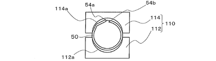
- FIG. 8 is a schematic diagram showing a part of the structure of the steel plate 50 and the reduced tube device 110 at the start of the reduced tube forming in the manufacturing process of the compressor 1 of the first embodiment.
- the first contraction mold 112 having the semicircular first groove 112 a and the semicircular second groove 114 a are included.
- a contraction device 110 having a second contraction die 114 is used.
- the first groove portion 112a of the first contraction tube mold 112 is disposed so as to face the second groove portion 114a of the second contraction tube mold 114.
- the steel plate 50 wound into a C-shape is sandwiched between the first groove portion 112a and the second groove portion 114a of the reduced tube apparatus 110.
- FIG. 9 is a schematic view showing the structure of the steel plate 50 and the reduced tube device 110 during the reduced tube forming in the manufacturing process of the compressor 1 of the first embodiment.
- the pressing direction of the second reduced tube mold 114 during the reduced tube forming is indicated by an arrow.
- the contraction device 110 performs an operation of pressing the second contraction mold 114 toward the first contraction mold 112.
- the first edge portion 54 a and the second edge portion 54 b of the steel plate 50 can be brought into contact with each other by the pressing operation of the second contraction die 114.
- the steel plate 50 sandwiched between the first groove portion 112a and the second groove portion 114a is formed into a cylindrical shape by the pressing operation of the second contraction die 114.
- an operation of moving the second reduced tube mold 114 in a direction away from the steel plate 50 is performed.
- the steel plate 50 is removed from the first reduced tube mold 112 in the reduced tube apparatus 110.
- the C-shaped steel plate 50 is reduced into the cylindrical steel plate 50 by the tube forming. Is done.
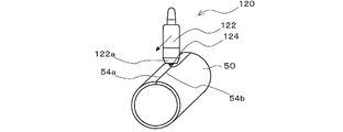
- FIG. 10 is a schematic diagram illustrating a partial structure of the steel plate 50 and the butt welding apparatus 120 during butt welding in the manufacturing process of the compressor 1 according to the first embodiment.
- the moving direction of the butt welding apparatus 120 in butt welding is indicated by an arrow.
- the first edge portion 54 a and the second edge portion 54 b of the steel plate 50 formed into a cylindrical shape by reduced tube forming are joined by a butt welding device 120.
- the body portion 2 a of the cylindrical pressure sealed container 2 is formed by butt welding of the steel plate 50.
- the butt welding device 120 can be configured as, for example, a resistance welding welding device such as seam welding or an arc welding welding device such as TIG welding.
- the butt welding device 120 includes a first welding torch 122 that welds the first edge portion 54a and the second edge portion 54b of the steel plate 50.
- the butt welding apparatus 120 for example, a welding power source that converts AC power supplied from a commercial AC power source into power used for welding, and amplifies the current flowing from the welding power source for welding.
- a welding transformer that flows through the first welding torch 122.
- a first welding electrode 124 is attached to the distal end portion 122 a of the first welding torch 122.
- the first welding electrode 124 can be configured as, for example, a pure metal electrode such as a pure tungsten electrode or a pure molybdenum electrode, or an alloy electrode such as a copper chromium alloy electrode or a copper alumina alloy electrode.
- the step of expanding and forming the body portion 2a of the pressure-sealed container 2 is to reduce the distortion of the body portion 2a of the pressure-sealed container 2 manufactured by winding the steel sheet 50, reducing the tube shape, and butt welding. Will be referred to as “first tube expansion molding”.
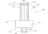
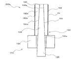
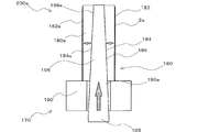
- FIG. 11 is a schematic diagram showing an example of the external structure of the first tube expansion device 130 of the first tube expansion device 200a used in the first tube expansion molding in the manufacturing process of the compressor 1 of the first embodiment.
- the first tube expanding device 130 is configured as a jig that constitutes a part of the first tube expanding device 200a. As shown in FIG. 11, the first tube expansion device 130 supports the first tube expansion mold portion 140 and the first tube expansion mold portion 140 that performs the first tube expansion molding of the body portion 2 a of the pressure sealed container 2. And a casing part 150. In addition, the first tube expanding device 130 includes a first rod portion 155 that is reciprocally disposed inside the first tube expanding mold portion 140 and the first casing portion 150.
- the outer surface portion 141 of the first tube expansion mold portion 140 includes a first outer surface portion 142 having a circumferential shape, a second outer surface portion 143 having a smaller radius than the first outer surface portion 142, and a first outer surface portion 142. And a third outer surface portion 144 extending between the first outer surface portion 143 and the second outer surface portion 143. That is, the outer surface 141 of the first tube expansion mold 140 has two circumferential surfaces with different radii. In FIG. 11, the first outer surface part 142 of the first tube expansion mold part 140 is arranged on the first casing part 150 side.
- first tube expansion mold part 140 includes a plurality of first split molds 140a arranged adjacent to the outer surface part 141 of the first tube expansion mold part 140 in the circumferential direction.
- the shapes of the first divided molds 140a can all be the same.
- the outer surface 141a of the first split mold 140a includes a first curved surface portion 142a having a circular arc shape that is a part of the first outer surface portion 142, and a second curved shape having a circular arc shape that is a part of the second outer surface portion 143. And a surface portion 143a. Further, the outer side surface 141a of the first split mold 140a is a part of the third outer side surface portion 144, and has a connecting surface portion 144a extending between the first curved surface portion 142a and the second curved surface portion 143a. Yes.
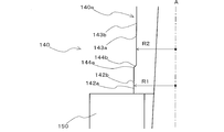
- FIG. 12 is a schematic view showing a part of the cross-sectional structure of the first tube expansion mold part 140 of FIG.
- the center line A of the first tube expansion mold part 140 connecting the center of the first outer surface part 142 and the center of the second outer surface part 143 is shown by a one-dot chain line.
- the lengths of the radii of the first outer surface portion 142 and the second outer surface portion 143 are indicated by solid arrows.
- the radius R1 of the first curved surface portion 142a of the first split mold 140a is configured to be larger than the radius R2 of the second curved surface portion 143a of the first split mold 140a. Further, at the time of the first tube expansion molding, the radius R1 of the first curved surface portion 142a is expanded to the inner diameter of the body portion 2a of the pressure sealed container 2 in the finished product of the compressor 1, but the second curved surface portion 143a The radius R1 is configured to be larger than the radius R2 of the second outer surface portion 143.
- the 3rd outer side surface part 144 extended between the 1st outer side surface part 142 and the 2nd outer side surface part 143 can be comprised so that it may become a taper shape, for example.
- the cross-sectional portion 144 b of the third outer surface portion 144 along the center line A is from the linear cross-section portion 142 b of the first outer surface portion 142 to the linear cross-section portion of the second outer surface portion 143. It can be configured to have a linear shape extending obliquely toward 143b.
- the third outer surface portion 144 is configured to have a tapered shape
- the cross-sectional portion 144b of the third outer surface portion 144 along the center line A is configured to have a linear shape. You may comprise so that it may become.
- modified examples of the cross-sectional shape of the third outer surface portion 144 of the first tube expansion mold portion 140 will be described with reference to FIGS. 13 to 16. In FIGS. That is, only the cross-sectional shape of the third outer surface portion 144 of the first tube expansion mold portion 140 will be described.
- FIG. 13 is a schematic view showing a modification of the shape of the cross-sectional portion 144b of the third outer surface portion 144 in the first tube expanding device 130 of the first embodiment.
- the center line A of the first tube expansion mold portion 140 connecting the center of the first outer surface portion 142 and the center of the second outer surface portion 143 is shown by a one-dot chain line.
- the lengths of the radii of the first outer surface portion 142 and the second outer surface portion 143 are indicated by solid arrows. As shown in FIG.
- the cross-sectional portion 144 b of the third outer surface portion 144 of the first tube expansion mold portion 140 is a linear cross-sectional portion 142 b of the first outer surface portion 142 and a linear cross-sectional portion of the second outer surface portion 143. It can comprise so that it may become a linear shape orthogonal to 143b.
- FIG. 14 is a schematic diagram illustrating another modification of the cross-sectional portion 144b of the third outer surface portion 144 in the first tube expanding device 130 of the first embodiment.
- the center line A of the first tube expansion mold part 140 connecting the center of the first outer surface part 142 and the center of the second outer surface part 143 is shown by a one-dot chain line.
- the lengths of the radii of the first outer surface portion 142 and the second outer surface portion 143 are indicated by solid arrows.
- the 3rd outer side surface part 144 becomes convex shape, and the cross-sectional part 144b of the 3rd outer side surface part 144 can be comprised so that it may become a quarter circle shape.
- FIG. 15 is a schematic diagram illustrating another modification of the cross-sectional portion 144b of the third outer surface portion 144 in the first tube expanding device 130 of the first embodiment.
- the center line A of the first tube expansion mold part 140 connecting the center of the first outer surface part 142 and the center of the second outer surface part 143 is shown by a one-dot chain line.
- the lengths of the radii of the first outer surface portion 142 and the second outer surface portion 143 are indicated by solid arrows.
- the third outer surface part 144 can be formed in a concave shape, and the cross-sectional part 144 b of the third outer surface part 144 can be formed in a quadrant.
- FIG. 16 is a schematic diagram illustrating another modification of the cross-sectional portion 144b of the third outer surface portion 144 in the first tube expanding device 130 of the first embodiment.
- the center line A of the first tube expansion mold part 140 connecting the center of the first outer surface part 142 and the center of the second outer surface part 143 is shown by a one-dot chain line.
- the lengths of the radii of the first outer surface portion 142 and the second outer surface portion 143 are indicated by solid arrows. As shown in FIG.
- the third outer surface part 144 can have a plurality of convex parts and concave parts, and the cross-sectional part 144 b of the third outer surface part 144 has a plurality of four parts. It can be configured to have a semicircular shape.
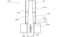
- FIG. 17 is a schematic view showing the internal structure of the first tube expanding device 130 of FIG.
- a first hollow space portion 146 having a polygonal truncated pyramid shape surrounded by an inner side surface portion 145 of the first tube expansion mold portion 140 is provided inside the first tube expansion mold portion 140.
- the inner side surface part 145 of the first tube expanding mold part 140 has a plurality of trapezoidal flat surface parts 145a which are the inner side surfaces of the first split mold 140a.
- the first hollow space portion 146 is configured as a polygonal frustum-shaped space by being surrounded by the flat surface portion 145a of the first split mold 140a.
- the first hollow space portion 146 is configured as a polygonal frustum-shaped space that decreases as the opening area of the first hollow space portion 146 moves away from the first casing portion 150.
- the first casing part 150 has a second hollow space part 150 a that communicates the external space of the first casing part 150 and the first hollow space part 146.
- the second hollow space 150a can be a cylindrical space having an opening area larger than that of the first hollow space 146, for example.
- the first casing portion 150 is fixed to a support base of the first tube expansion device 200a in order to ensure stability during the first tube expansion molding and reliability in the first tube expansion molding.
- the shape of the 1st casing part 150 should just be a shape fixable to a support stand, for example, can be comprised so that it may have external appearance, such as a cube shape and a cylindrical shape.
- the first rod portion 155 has a polygonal trapezoidal insertion portion 158 having a plurality of trapezoidal outer surface portions 158a as shown in FIG.
- the number of trapezoidal outer surface portions 158a in the polygonal frustum-shaped insertion portion 158 is the same as the number of the first split mold 140a.
- the insertion portion 158 of the first rod portion 155 is inserted into the first hollow space portion 146 of the first tube expansion mold portion 140 via the second hollow space portion 150a of the first casing portion 150. Contained. 11 and 17, the first outer surface 142 is completed by pushing the insertion portion 158 of the first rod portion 155 toward the first tube expansion mold 140.
- the inner diameter of the body portion 2a of the pressure sealed container 2 in the product is expanded.
- first tube expanding device 130 can be variously modified.
- modified examples of the structure of the first tube expanding device 130 will be described with reference to FIGS. 18 to 20.
- FIGS. 18 to 20 only the structure of a portion different from FIG. 11 or FIG.
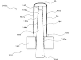
- FIG. 18 is a schematic diagram illustrating another modified example of the external structure of the first tube expansion device 130 of the first tube expansion device 200a used in the first tube expansion molding in the manufacturing process of the compressor 1 of the first embodiment. .
- the first outer surface part 142 of the first pipe expanding mold part 140 is disposed on the first casing part 150 side.
- the first outer surface portion 142 of the first tube expansion mold portion 140 can be disposed so as to be located on the opposite side of the first casing portion 150.
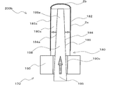
- FIG. 19 is a schematic diagram illustrating another modified example of the external structure of the first tube expansion device 130 of the first tube expansion device 200a used in the first tube expansion molding in the manufacturing process of the compressor 1 according to the first embodiment.
- . 20 is a schematic view showing the internal structure of the first tube expanding device 130 of FIG. 19 and 20, the first hollow space portion 146 is configured as a truncated pyramid-shaped space that decreases as the opening area of the first hollow space portion 146 moves away from the first casing portion 150. Is done.
- the insertion portion 158 of the first rod portion 155 is inserted through the second hollow space portion 150 a of the first casing portion 150 into the first tube expanding mold portion 140.
- One hollow space 146 is accommodated.
- the insertion portion 158 of the first rod portion 155 is inserted into the second hollow portion 146 of the first casing portion 150 via the first hollow space portion 146 of the first tube expansion mold portion 140. It can comprise so that it may be accommodated in the space part 150a. 19 and 20, the first outer surface 142 in the finished product of the compressor 1 is obtained by pulling the insertion portion 158 of the first rod portion 155 in the direction of the first casing portion 150.
- the inner diameter of the body portion 2a of the pressure sealed container 2 is expanded.
- FIG. 21 shows a cross-sectional structure of the body portion 2a of the pressure-sealed container 2 and a partial cross-sectional structure of the first tube expansion device 200a before the first tube expansion molding in the manufacturing process of the compressor 1 of the first embodiment.
- FIG. FIG. 22 is a schematic diagram illustrating a cross-sectional structure of the body portion 2a of the pressure-sealed container 2 and a partial cross-sectional structure of the first tube expansion device 200a during the first tube expansion molding in the manufacturing process of the compressor 1 according to the first embodiment.
- the moving direction of the first rod portion 155 during the first tube expansion molding is indicated by a block arrow with a hatching line, and the first tube expansion die portion 140 in accordance with the movement of the first rod portion 155 is the first.
- the moving direction of the divided mold 140a is indicated by a white block arrow.
- the first tube expanding device 130 shown in FIGS. 21 and 22 has the same structure as the first tube expanding device 200a shown in FIGS. 11, 12, and 17.
- the third outer surface portion 144 extending between the first outer surface portion 142 and the second outer surface portion 143 is configured to have a tapered shape.
- the cross-sectional portion 144b of the third outer surface portion 144 of FIGS. 21 and 22 is obliquely directed from the linear cross-sectional portion 142b of the first outer surface portion 142 toward the linear cross-sectional portion 143b of the second outer surface portion 143. It can be configured to have an extending linear shape.
- the first outer surface portion 142 of the first tube expansion mold portion 140 is disposed on the first casing portion 150 side.
- the first hollow space portion 146 has a polygonal truncated pyramid-shaped space that decreases as the opening area of the first hollow space portion 146 increases from the first casing portion 150. It is configured as. 21 and 22, the insertion portion 158 of the first rod portion 155 is inserted into the first tube expansion mold portion 140 via the second hollow space portion 150a of the first casing portion 150. Is accommodated in the first hollow space 146.
- the inner side surface of the body portion 2a of the pressure sealed container 2 is disposed so as to be in contact with the first outer side surface portion 142 of the first tube expansion mold portion 140.
- the insertion portion 158 of the first rod portion 155 is changed from the second hollow space portion 150a to the first hollow space portion 146 by the pressing of the first rod portion 155 or the like. Move in a straight line.
- the outer side surface portion 158 a of the insertion portion 158 slides along the inner side surface portion 145 of the first tube expansion mold portion 140.
- the first divided mold 140a of the first tube expansion mold portion 140 becomes the first divided mold. It moves in the direction of the outer surface 141a of 140a.
- the body portion 2a of the pressure sealed container 2 is expanded.
- the inner diameter of the first inner side surface 2a1 of the body part 2a that contacts the first curved surface part 142a of the first split mold 140a is the inner diameter of the body part 2a of the pressure sealed container 2 in the finished product of the compressor 1.
- Tube expansion is performed until the dimensions are the same.
- the inner diameter of the second inner side surface 2a2 of the body portion 2a that contacts the second curved surface portion 143a of the first tube expanding mold portion 140 is larger than the inner diameter dimension of the body portion 2a of the pressure sealed container 2 in the finished product of the compressor 1.
- the tube is formed so as to be small.
- the third inner side surface 2a3 extending between the first inner side surface 2a1 and the second inner side surface 2a2 is expanded and formed into a tapered shape.
- drum 2a of the pressure sealed container 2 becomes large by making the quantity of the 1st division mold 140a into an odd number.
- the adjacent first split mold 140a contacts the inner side surface of the body part 2a of the pressure sealed container 2, a gap is formed between the adjacent first split molds 140a, and the first side surface of the body part 2a has the first side. A portion where the split mold 140a does not come into contact occurs.
- convex protrusions are formed on the inner surface of the body part 2a where the adjacent first divided mold 140a does not contact, and distortion occurs in the inner diameter of the body part 2a.
- the convex protrusions are formed at positions facing the inner surface of the body part 2a, so that the distortion of the inner diameter of the body part 2a increases.
- the number of the first divided molds 140a is an odd number, it is possible to avoid the formation of the convex protrusions at positions facing the inner surface of the body part 2a. An increase in the distortion of the inner diameter can be avoided.
- FIG. 23 is a schematic diagram showing the structure of the body portion 2a of the pressure-sealed container 2 during end face processing in the manufacturing process of the compressor 1 of the first embodiment.
- the first peripheral portion 2a4 and the second peripheral portion 2a5 are cut by an end surface processing device such as a lathe.
- the 1st peripheral part 2a4 be a terminal part by the side of the 1st inner surface 2a1 of the trunk
- the second peripheral edge 2a5 is a terminal portion on the second inner side surface 2a2 side of the body portion 2a of the pressure-sealed container 2.
- the width between the first peripheral edge 2a4 and the second peripheral edge 2a5 of the body part 2a of the pressure sealed container 2 by the end face processing of the body part 2a of the pressure sealed container 2 is the pressure sealed container in the finished product of the compressor 1. It is processed so as to be the same as the width of the body part 2a.
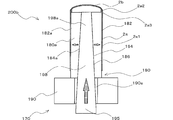
- FIG. 24 shows the structure of the body portion 2a and the bottom portion 2b of the pressure sealed container 2 during circumferential welding and a part of the circumferential welding device 160 in the manufacturing process of the compressor 1 according to the first embodiment of the present invention.
- FIG. The bottom 2b of the pressure sealed container 2 is manufactured by plastic forming a plate member made of steel such as stainless steel or carbon steel.
- the first inner side surface 2 a 1 of the body portion 2 a of the pressure sealed container 2 after end face processing is joined to the outer surface 2 b 1 of the bottom 2 b of the pressure sealed container 2 by a circumferential welding device 160.
- the circumferential welding device 160 can be configured as, for example, a resistance welding welding device such as projection welding or seam welding, or an arc welding welding device such as TIG welding.
- the circumferential welding device 160 includes a second welding torch 162 that performs welding between the first inner side surface 2a1 of the body portion 2a of the pressure sealed container 2 and the outer side surface 2b1 of the bottom portion 2b of the pressure sealed container 2.
- the circumferential welding device 160 uses, for example, a welding power source that converts AC power supplied from a commercial AC power source into power used for welding, and a current flowing from the welding power source for welding.
- a welding transformer that amplifies and flows to the second welding torch 162.
- a second welding electrode 164 is attached to the distal end portion 162 a of the second welding torch 162.
- the second welding electrode 164 can be configured as, for example, a pure metal electrode such as a pure tungsten electrode or a pure molybdenum electrode, or an alloy electrode such as a copper chrome alloy electrode or a copper alumina alloy electrode.
- the gap between the first inner side surface 2a1 of the body portion 2a of the pressure sealed container 2 and the outer side surface 2b1 of the bottom portion 2b of the pressure sealed container 2 is sealed by welding by the circumferential welding device 160.
- the first inner side surface 2a1 of the body portion 2a of the pressure sealed container 2 and the outer side surface 2b1 of the bottom portion 2b of the pressure sealed container 2 are joined by welding, but may be joined by brazing or the like.
- the suction hole 5 is formed in the body portion 2a of the pressure sealed container 2 by a drilling device such as a drill. Further, the connection pipe 6b and the ring 6c are joined to the suction hole 5 of the body part 2a by welding or brazing.
- tube expansion by the second tube expansion device 200b is performed in order to reduce the above-described distortion and to make the inner diameter of the body portion 2a of the pressure sealed container 2 uniform.
- pipe expansion molding by the second pipe expansion device 200b is referred to as “second pipe expansion molding”.
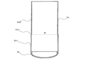
- FIG. 25 is a cross-sectional view schematically showing the structure of the body portion 2a and the bottom portion 2b of the pressure-sealed container 2 to be expanded by second tube expansion in the manufacturing process of the compressor 1 of the first embodiment.
- a thermosetting portion 60 is formed by welding or the like between the first inner side surface 2a1 of the body portion 2a of the pressure sealed container 2 and the outer side surface 2b1 of the bottom portion 2b of the pressure sealed container 2. ing.
- the hardness of the thermosetting part 60 is higher than the other part of the trunk
- the third inner side surface 2 a 3 of the body portion 2 a of the pressure sealed container 2 is disposed adjacent to the peripheral edge 2 b 2 of the bottom 2 b of the pressure sealed container 2.
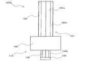
- FIG. 26 is a schematic diagram illustrating an example of an external structure of a part of the second tube expansion device 170 of the second tube expansion device 200b used in the second tube expansion molding in the manufacturing process of the compressor 1 according to the first embodiment.
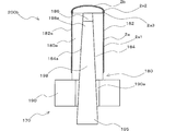
- FIG. 27 is a schematic view showing the internal structure of the second tube expanding device 170 of FIG.
- the 2nd tube expansion instrument 170 is comprised as a jig
- the second tube expansion instrument 170 is a second tube expansion mold portion 180 that performs the second tube expansion molding of the body portion 2 a of the pressure sealed container 2, and the second tube expansion mold portion 180 that supports the second tube expansion mold portion 180.
- the second tube expansion instrument 170 includes a second rod portion 195 that is reciprocally disposed inside the second tube expansion mold portion 180 and the second casing portion 190.
- the second expansion mold part 180 has a circumferential outer surface part 182.
- the second tube expansion mold part 180 includes a plurality of second divided molds 180 a arranged adjacent to the outer surface 182 of the second tube expansion mold part 180 in the circumferential direction.
- the second divided mold 180a has an arcuate curved surface portion 182a. It should be noted that, like the first split mold 140a of the first tube expansion mold part 140, the second split mold 180a can have the same shape. Similarly to the first divided mold 140a of the first tube expansion mold part 140, the number of the second divided molds 180a is an odd number, so that the distortion of the inner diameter of the body part 2a of the pressure sealed container 2 is reduced. An increase in size can be avoided.
- a first hollow space portion 186 having a polygonal truncated pyramid shape surrounded by an inner side surface portion 184 of the second tube expansion mold portion 180 is provided inside the second tube expansion mold portion 180.
- the inner side surface part 184 of the second tube expansion mold part 180 has a plurality of trapezoidal flat surface parts 184a which are the inner side surfaces of the second split mold 180a.
- the first hollow space 186 is configured as a polygonal frustum-shaped space by being surrounded by the flat surface 184a of the second divided mold 180a.
- the first hollow space portion 186 is configured as a polygonal frustum-shaped space that decreases as the opening area of the first hollow space portion 186 increases from the second casing portion 190.
- the second casing portion 190 has a second hollow space portion 190a that communicates the external space of the second casing portion 190 with the first hollow space portion 186.
- the second hollow space 190a can be a cylindrical space having an opening area larger than that of the first hollow space 186, for example.
- the second casing portion 190 is fixed to the support base of the second tube expansion device 200b in order to ensure the stability during the first tube expansion molding and the reliability in the first tube expansion molding.
- the shape of the 2nd casing part 190 should just be a shape which can be fixed to a support stand, for example, can be comprised so that it may have external appearance, such as a cube shape and a cylindrical shape.
- the second rod portion 195 has a polygonal-frustum-shaped insertion portion 198 having a plurality of trapezoidal outer surface portions 198a.
- the number of trapezoidal outer surface portions 198a in the polygonal trapezoidal insertion portion 198 is the same as the number of the second divided mold 180a.
- the insertion part 198 of the second rod part 195 is accommodated in the first hollow space part 186 of the second tube expansion mold part 180 via the second hollow space part 190a of the second casing part 190.
- the outer surface portion 182 of the second expanding device 170 in the finished product of the compressor 1 is pushed by pushing the insertion portion 198 of the second rod portion 195 toward the second expanding die portion 180.
- the inner diameter of the body portion 2a of the pressure sealed container 2 is expanded.
- FIG. 28 shows a cross-sectional structure of the body portion 2a and the bottom portion 2b of the pressure sealed container 2 and a part of the second tube expansion device 200b before the second tube expansion molding in the manufacturing process of the compressor 1 according to the first embodiment. It is the schematic which shows an example of a cross-sectional structure.
- FIG. 29 shows a cross-sectional structure of the body portion 2a and the bottom portion 2b of the pressure-sealed container 2 and a partial cross-sectional structure of the second tube expansion device 200b in the manufacturing process of the compressor 1 according to the first embodiment. It is the schematic which shows an example. In FIG.
- the moving direction of the second rod portion 195 during the second tube expansion molding is indicated by a block arrow with a hatching line, and the second tube expansion die portion 180 of the second tube expansion die portion 180 accompanying the movement of the second rod portion 195 is shown.
- the moving direction of the divided mold 180a is indicated by a white block arrow.
- the second inner side surface 2a2 and the third inner side surface 2a3 of the body portion 2a of the pressure sealed container 2 are arranged so as to come into contact with the outer side surface portion 182 of the second tube expansion mold portion 180.
- the insertion portion 198 of the second rod portion 195 is changed from the second hollow space portion 190a to the first hollow space portion 186 by the pressing of the second rod portion 195 or the like. Move in a straight line.
- the outer side surface portion 198 a of the insertion portion 198 slides along the inner side surface portion 184 of the second tube expansion mold portion 180.
- the outer side surface portion 198a of the insertion portion 198 slides along the inner side surface portion 184 of the second tube expansion mold portion 180, whereby the second divided mold 180a of the second tube expansion mold portion 180 becomes the second divided mold. It moves in the direction of the curved surface portion 182a of 180a.
- the body part 2a of the pressure sealed container 2 is expanded.
- the inner diameters of the second inner side surface 2a2 and the third inner side surface 2a3 of the body part 2a that are in contact with the curved surface part 182a of the second split mold 180a are the inner diameter dimensions of the body part 2a of the pressure sealed container 2 in the finished product of the compressor 1. Is expanded until it becomes the same, and the inner diameter becomes uniform.
- FIG. 30 is a schematic diagram illustrating another example of the cross-sectional structures of the body portion 2a and the bottom portion 2b of the pressure sealed container 2 before the second tube expansion molding in the manufacturing process of the compressor 1 of the first embodiment. .
- FIG. 30 is a schematic diagram illustrating another example of the cross-sectional structures of the body portion 2a and the bottom portion 2b of the pressure sealed container 2 before the second tube expansion molding in the manufacturing process of the compressor 1 of the first embodiment. .
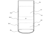
- FIG. 31 is a schematic diagram illustrating another example of the cross-sectional structures of the body portion 2a and the bottom portion 2b of the pressure-sealed container 2 after the second tube expansion molding in the manufacturing process of the compressor 1 according to the first embodiment. is there. 30 and 31, the arrangement position of the third inner side surface 2a3 of the body portion 2a of the pressure sealed container 2 is illustrated by a dotted line segment B. Further, in FIG. 31, in order to schematically show an electric motor part fixing position 70 for fixing the electric motor part 10 and a compression mechanism part fixing position 80 for fixing the compression mechanism part 30 in the body part 2 a of the pressure sealed container 2. The electric motor unit 10 and the compression mechanism unit 30 are indicated by broken lines.
- the second tube expansion mold part 180 can be formed by tube expansion so that the inner diameter of the pressure sealed container 2 becomes uniform.
- distortion may remain on the inner surface of the pressure sealed container 2 even after the third inner surface 2 a 3 is expanded. Therefore, the third inner side surface 2a3 is formed away from the motor unit fixing position 70 and the compression mechanism unit fixing position 80, thereby more reliably avoiding the deterioration of the performance of the compressor 1 and the reliability of the compressor 1. Can be improved.
- the electric motor unit 10, the crankshaft 20, and the compression mechanism unit 30 are accommodated in the body unit 2a of the pressure sealed container 2 after the second tube expansion device 200b.
- the compression mechanism part 30 is joined to the inner surface of the body part 2a of the pressure sealed container 2 by arc welding such as arc spot welding or shrink fitting.
- the electric motor unit 10 is joined to the inner side surface of the body portion 2a of the pressure sealed container 2 by shrink fitting or the like.
- the lid portion 2c of the pressure sealed container 2 is connected to the body portion 2a of the pressure sealed container 2 by circumferential welding or the like.
- the second peripheral edge 2a5 is joined to the inner side surface.
- the lid portion 2c of the pressure sealed container 2 is manufactured by plastic forming a steel plate member such as stainless steel or carbon steel.
- the discharge pipe 7 and the glass terminal 8 are joined by welding such as resistance welding or brazing before joining to the body part 2a of the pressure sealed container 2. Yes.
- the glass terminal 8 and the coil wound around the stator 12 are electrically connected by the conductive wire 16 before being joined to the body portion 2 a of the pressure sealed container 2.
- the suction muffler 3 is attached to the outer surface of the pressure sealed container 2. Furthermore, the extension pipe 6a is joined to the connection pipe 6b by welding such as brazing or resistance welding, and the suction pipe 4 is joined to the connection pipe 6b by welding such as brazing or resistance welding. With the above, the manufacturing process of the compressor 1 of the first embodiment is completed.
- FIG. 32 is a schematic diagram illustrating an example of a cross-sectional structure of the body portion 2a of the pressure sealed container 2 and a partial cross-sectional structure of the first tube expansion device 200a before the first tube expansion molding in the manufacturing process of the conventional compressor 1.
- FIG. 32 is a schematic diagram illustrating an example of a cross-sectional structure of the body portion 2a of the pressure sealed container 2 and a partial cross-sectional structure of the first tube expansion device 200a before the first tube expansion molding in the manufacturing process of the conventional compressor 1.
- the tube expansion device of the first tube expansion device 200a one having a tube expansion mold portion having a circumferential outer surface portion 182 similar to that of the second tube expansion device 170 is used.
- the second tube expansion device 170 is used as an example of the tube expansion device of the first tube expansion device 200a.
- movement, etc. of the 2nd tube expansion instrument 170 are the same as what was mentioned above, description is abbreviate
- FIG. 33 is a schematic diagram illustrating an example of a cross-sectional structure of the body portion 2a of the pressure sealed container 2 and a partial cross-sectional structure of the first tube expansion device 200a during the first tube expansion molding in the manufacturing process of the conventional compressor 1. is there.
- the movement direction of the second rod portion 195 during the first tube expansion molding is indicated by a block arrow with a hatching line, and the second tube expansion mold portion 180 of the second tube expansion mold portion 180 accompanying the movement of the second rod portion 195 is shown.
- the moving direction of the divided mold 180a is indicated by a white block arrow.
- the second divided mold 180a of the second tube expansion mold portion 180 is replaced with the second divided mold 180a. It moves in the direction of the curved surface portion 182a.
- the inner diameter of the body portion 2a of the pressure sealed container 2 is the same as that of the pressure sealed container 2 in the finished product of the compressor 1. Tube expansion is performed until the inner diameter of the body portion 2a is the same.
- the end face processing of the body part 2a of the pressure sealed container 2 and the bottom part of the pressure sealed container 2 are the same as in the manufacturing process of the compressor 1 of the first embodiment. Circumferential welding to the body portion 2a of 2b is performed. After the circumferential welding of the bottom 2b of the pressure-sealed container 2 to the body 2a, in the manufacturing process of the conventional compressor 1, the first tube expansion process similar to the manufacturing process of the compressor 1 of the first embodiment is performed. Is called.
- FIG. 34 shows an example of a cross-sectional structure of the body portion 2a and the bottom portion 2b of the pressure sealed container 2 and a partial cross-sectional structure of the second tube expansion device 200b before the second tube expansion molding in the manufacturing process of the conventional compressor 1.
- FIG. 35 shows an example of the cross-sectional structure of the body portion 2a and the bottom portion 2b of the pressure-sealed container 2 and the partial cross-sectional structure of the second tube expansion device 200b in the manufacturing process of the conventional compressor 1 during the second tube expansion molding.
- the movement direction of the second rod portion 195 during the second tube expansion molding is indicated by a block arrow with a hatching line, and the second tube expansion die portion 180 of the second tube expansion mold portion 180 accompanying the movement of the second rod portion 195 is shown.
- the moving direction of the divided mold 180a is indicated by a white block arrow.
- the second split mold 180a of the second tube expansion mold portion 180 is replaced with the second split mold 180a in accordance with the movement of the second rod portion 195. It moves in the direction of the curved surface portion 182a.
- the inner diameter of the body portion 2a of the pressure sealed container 2 is the same as that of the pressure sealed container 2 in the finished product of the compressor 1. Tube expansion is performed until the inner diameter of the body portion 2a is the same.
- FIG. 36 is a cross-sectional view schematically showing the structure of the body portion 2a and the bottom portion 2b of the pressure sealed container 2 after the second tube expansion molding in the manufacturing process of the conventional compressor 1.
- thermosetting by welding or the like.
- a portion 60a is formed between the inner surface of the body portion 2a of the pressure sealed container 2 on the first peripheral edge 2a4 side and the outer surface 2b1 of the bottom 2b of the pressure sealed container 2, thermosetting by welding or the like.
- a portion 60a is formed. Since the hardness of the thermosetting portion 60a is higher than the other portions of the body portion 2a, the body portion 2a of the pressure-sealed container 2 is formed in the direction from the thermosetting portion 60a to the second peripheral portion 2a5 by the second tube expansion molding.
- a tapered distortion portion 90 is generated.
- the width of the distortion portion 90 in the inner diameter direction of the body portion 2a may be 20 to 30 ⁇ m in the manufacturing process of the compressor 1.
- the compression mechanism portion 30 is fixed to the pressure-sealed container 2 in a distorted state, so that the performance of the compressor is lowered, and the reliability of the compressor Cause a drop.
- FIG. 37 shows the width of distortion of the body portion 2a of the pressure sealed container 2 after the second tube expansion molding in the manufacturing process of the conventional compressor 1, and the second tube expansion molding in the manufacturing process of the compressor 1 of the first embodiment. It is the graph which compared relatively with the width
- FIG. 37 the width of the distortion after the second tube expansion molding in the manufacturing process of the conventional compressor 1 is based on the inner diameter of the body portion 2a of the pressure sealed container 2 of the finished product. The width of the distortion in the body portion 2a is shown by a triangular blot.
- the width of the distortion after the second tube expansion molding in the manufacturing process of the compressor 1 according to the first embodiment is based on the inner diameter of the body portion 2a of the pressure sealed container 2 of the finished product, as shown in FIG.
- the width of the strain on the second inner side surface 2a2 and the third inner side surface 2a3 of the second body part 2a is shown by a circular blot.
- FIG. 37 the position of the inner diameter of the body portion 2a of the pressure sealed container 2 as a finished product is indicated by a thick vertical line. Moreover, the position of the peripheral edge 2b2 of the bottom 2b of the pressure sealed container 2 is shown by a thick horizontal line. That is, the blot on the right side of the thick vertical line in the graph of FIG. 37 indicates the width of the distortion in the radial direction, and the blot below the thick horizontal line indicates the width of the distortion in the central axis direction.
- the width of the radial strain after the second tube expansion molding of the first embodiment is the same as that after the conventional second tube expansion molding. Can be reduced to half or less of the width of the distortion. Accordingly, in the body portion 2a of the pressure sealed container 2 in the manufacturing process of the compressor 1 of the first embodiment, the distortion in the body portion 2a of the pressure sealed container 2 after the second tube expansion molding can be reduced. It is possible to avoid a decrease in the performance of the compressor 1 due to being fixed to the pressure sealed container 2 in a distorted state.
- the width of the radial strain after the second tube expansion molding of the first embodiment can be reduced to 60% or less of the width of the strain after the conventional second tube expansion molding. . Therefore, in the body part 2a of the pressure sealed container 2 in the manufacturing process of the compressor 1 according to the first embodiment, it is possible to reduce the occurrence of distortion in the body part 2a of the pressure sealed container 2 after the second tube expansion molding.
- the compression mechanism section 30 is placed at a position adjacent to the bottom 2b of the pressure sealed container 2 by reducing the occurrence of distortion. Since it can be accommodated, the compressor 1 can be downsized.
- the compressor 1 of the first embodiment includes the compression mechanism unit 30 that compresses the refrigerant, the crankshaft 20 that transmits the rotational driving force to the compression mechanism unit 30, and the rotational drive to the crankshaft 20.
- An electric motor unit 10 for generating force a cylindrical body part 2a, one end of the body part 2a, for example, a bottom part 2b joined to the first peripheral edge 2a4 side, and another end of the body part 2a, for example, a second And a lid portion 2c joined to the peripheral edge 2a5 side, accommodates the compression mechanism portion 30, the crankshaft 20, and the electric motor portion 10, and the compression mechanism portion 30 and the electric motor portion 10 are fixed to the body portion 2a.
- the body portion 2a has a smaller inner diameter than the first inner side surface 2a1 and the first inner side surface 2a1 by the first tube expansion molding performed before the bottom portion 2b is joined to the body portion 2a.
- the second inner surface 2a2 and The second inner surface 2a3 extending between the first inner surface 2a1 and the second inner surface 2a2 is formed, and the second inner portion is formed by the second tube expansion performed after the bottom portion 2b is joined to the body portion 2a.
- the side surface 2a2 and the third inner side surface 2a3 are expanded to the inner diameter of the first inner side surface 2a1.
- the manufacturing method of the compressor 1 of the first embodiment includes a cylindrical body portion 2a, one end of the body portion 2a, for example, a bottom portion 2b joined to the first peripheral edge portion 2a4 side, and the body portion 2a. It is a manufacturing method of the compressor 1 provided with the pressure sealed container 2 which has the other end, for example, the cover part 2c joined to the 2nd peripheral part 2a5 side, Comprising: Before the bottom part 2b is joined to the trunk
- the second inner side surface 2a2 and the third inner side surface 2a3 are expanded to the inner diameter of the first inner side surface 2a1.
- the first tube expansion device 130 which is the tube expansion device of the first embodiment is a first tube expansion device 130 for manufacturing the pressure sealed container 2 of the compressor 1, and has a cylindrical first outer surface portion 142 and the first tube expansion device 130.
- a tube-expansion mold having a second outer surface portion 143 having a smaller circumferential radius than the first outer surface portion 142 and a third outer surface portion 144 extending between the first outer surface portion 142 and the second outer surface portion 143.
- a first expansion die part 140 that is a part, a first casing part 150 that is a casing part that supports the first expansion mold part 140, and a reciprocation inside the first expansion die part 140 and the first casing part 150.
- the circumference of the first expansion mold part 140 with the movement of A plurality of first split molds 140a that move in the direction are provided, and each of the first split molds 140a includes a first curved surface part 142a having a circular arc surface shape that constitutes the first outer surface part 142, and a second outer surface part.
- the second curved surface portion 143a having an arcuate surface shape that configures 143 and the third outer surface portion 144, and a connecting surface portion 144a that extends between the first curved surface portion 142a and the second curved surface portion 143a.
- the body portion 2a in the first tube expansion molding, includes the first inner side surface 2a1, the second inner side surface 2a2 having a smaller inner diameter than the first inner side surface 2a1, and the first inner side surface.
- a third inner side surface 2a3 extending between 2a1 and the second inner side surface 2a2 can be formed. Thereafter, by performing the second tube expansion molding, the distortion of the body portion 2a can be reduced, so that the compression mechanism portion 30 can be prevented from being fixed to the pressure sealed container 2 in a distorted state.
- the compressor 1 capable of avoiding deterioration in performance and securing reliability due to the compression mechanism portion 30 being fixed to the pressure sealed container 2 in a distorted state, and manufacture of the compressor 1 It is possible to provide a method and a first tube expanding device 130 for manufacturing the pressure-sealed container 2.
- the third inner side surface 2a3 includes the compression mechanism portion fixing position 80, which is a fixing position with the compression mechanism portion 30 in the body portion 2a, and the electric motor. It can be formed at a position separated from the motor unit fixing position 70 which is a fixing position with the unit 10. According to the above-described configuration, it is possible to more reliably avoid a decrease in the performance of the compressor 1 and improve the reliability of the compressor 1.
- the third inner side surface 2a3 is positioned adjacent to the joining position with the bottom 2b in the body 2a, that is, the bottom of the pressure sealed container 2. It is formed at a position adjacent to the peripheral edge 2b2 of 2b. According to the above-described configuration, the compression mechanism 30 can be accommodated at a position adjacent to the bottom 2b of the pressure sealed container 2, so that the compressor 1 can be downsized.
- the tube expanding mold part can be configured to include an odd number of divided molds. According to the above-described configuration, it is possible to avoid the formation of the convex protrusions generated when the body part 2a is expanded at the position facing the inner side surface of the body part 2a, so that the distortion of the inner diameter of the body part 2a is large. Can be avoided.
- first welding torch 122 that performs butt welding may have the same structure as the second welding torch 162 that performs circumferential welding, or may have a different structure.
- first casing portion 150 and the first rod portion 155 of the first tube expanding device 130 may have the same structure as the second casing portion 190 and the second rod portion 195 of the second tube expanding device 170. , May have a different structure.
- the compressor 1 of the above-mentioned Embodiment 1 is refrigeration cycle apparatuses, such as an air conditioner water heater, a refrigerator, a vending machine, a humidifier, a dehumidifier, a dryer, a showcase, a washing dryer, etc., for example. It can be used.
Landscapes
- Engineering & Computer Science (AREA)
- Mechanical Engineering (AREA)
- General Engineering & Computer Science (AREA)
- Applications Or Details Of Rotary Compressors (AREA)
- Compressor (AREA)
- Mounting, Exchange, And Manufacturing Of Dies (AREA)
Abstract
圧縮機は、円筒形状の胴体部と、胴体部の一端に接合される底部と、胴体部の他の一端に接合される蓋部とを有し、圧縮機構部、クランクシャフト、及び電動機部を収容し、胴体部に圧縮機構部及び電動機部が固定された圧力密閉容器を備え、胴体部に底部が接合される前に行われる第1拡管成形により、胴体部に、第1内側面と、第1内側面よりも内径の小さい第2内側面と、第1内側面と第2内側面との間を延在する第3内側面とが形成され、胴体部に底部が接合された後に行われる第2拡管成形により、第2内側面及び第3内側面が、第1内側面の内径まで拡管成形される。また、圧縮機の製造方法は、上述の圧縮機を製造するためのものである。また、拡管器具は、上述の圧力密閉容器を製造するためのものである。
Description
本発明は、胴体部と底部と蓋部とを溶接により接合した圧力密閉容器を備える圧縮機、当該圧縮機の製造方法、及び当該圧力密閉容器を製造するために用いられる拡管器具に関する。
胴体部と底部と蓋部とを溶接により接合した圧力密閉容器を備える従来の圧縮機として、例えば特許文献1には、円筒体のケースと蓋体とをはめ合わせて、接触部分を溶接によって封止した密閉容器を備えるものが開示されている。
特許文献1と同様の構成を有する従来の圧縮機では、円筒体のケースと蓋体とを溶接によって封止した後に、圧縮機構部の外径と等しく、かつ均一な内径を有する内部空間を確保するために、円筒体のケースに拡管加工を施す必要がある。一方、特許文献1の圧縮機においては、円筒体のケースの蓋体との溶接部分が、熱硬化により、円筒体のケースの他の部分と比較して硬度が高くなっている。
円筒体のケースにおいて、溶接部分が他の部分と比較して硬度が高い場合、円筒体のケースに拡管加工を施すと、円筒体のケースの内径が均一にならず、円筒体のケースの溶接部分に隣接する部分がテーパ形状となる場合がある。テーパ形状となった円筒体のケースの部分に圧縮機構部が配置されると、圧縮機構部の側面部と円筒体のケースの内側面との間の隙間が一定とならないため、圧縮機構部が歪んだ状態で密閉容器に固定される場合がある。したがって、特許文献1の圧縮機では、圧縮機構部が歪んだ状態で密閉容器に固定されることにより、圧縮機の性能が低下し、圧縮機の信頼性を確保できないという課題があった。
本発明は、上述の課題を解決するものであり、圧縮機構部が歪んだ状態で圧力密閉容器に固定されることによる性能の低下の回避及び信頼性の確保が可能な圧縮機と、該圧縮機の製造方法と、該圧力密閉容器を製造可能な拡管器具とを提供することを目的とする。
本発明に係る圧縮機は、冷媒を圧縮する圧縮機構部と、前記圧縮機構部に回転駆動力を伝達するクランクシャフトと、前記クランクシャフトに回転駆動力を発生させる電動機部と、円筒形状の胴体部と、前記胴体部の一端に接合される底部と、前記胴体部の他の一端に接合される蓋部とを有し、前記圧縮機構部、前記クランクシャフト、及び前記電動機部を収容し、前記胴体部に前記圧縮機構部及び前記電動機部が固定された圧力密閉容器とを備え、前記胴体部に前記底部が接合される前に行われる第1拡管成形により、前記胴体部に、第1内側面と、前記第1内側面よりも内径の小さい第2内側面と、前記第1内側面と前記第2内側面との間を延在する第3内側面とが形成され、前記胴体部に前記底部が接合された後に行われる第2拡管成形により、前記第2内側面及び前記第3内側面が、前記第1内側面の内径まで拡管成形される。
また、本発明に係る圧縮機の製造方法は、円筒形状の胴体部と、前記胴体部の一端に接合される底部と、前記胴体部の他の一端に接合される蓋部とを有する圧力密閉容器を備える圧縮機の製造方法であって、前記胴体部に前記底部が接合される前に、第1内側面と、前記第1内側面よりも内径の小さい第2内側面と、前記第1内側面と前記第2内側面との間を延在する第3内側面とを前記胴体部に形成する第1拡管成形工程と、前記胴体部に前記底部が接合された後に、前記第2内側面と前記第3内側面とを、前記第1内側面の内径まで拡管成形する第2拡管成形工程とを有する。
また、本発明に係る拡管器具は、圧縮機の圧力密閉容器を製造するための拡管器具であって、円筒形状の第1外側面部と、前記第1外側面部より円周面の半径が小さい第2外側面部と、前記第1外側面部と前記第2外側面部との間を延在する第3外側面部とを有する拡管金型部と、前記拡管金型部を支持するケーシング部と、前記拡管金型部及び前記ケーシング部の内部に往復自在に配置されたロッド部とを備え、前記拡管金型部は、前記拡管金型部の円周方向に隣接して配置され、前記ロッド部の移動に伴い前記拡管金型部の円周面方向に移動する複数の分割金型を備えており、前記分割金型の各々は、前記第1外側面部を構成する円弧面形状の第1湾曲面部と、前記第2外側面部を構成する円弧面形状の第2湾曲面部と、前記第3外側面部を構成し、前記第1湾曲面部と前記第2湾曲面部との間を延在する連結面部とを有する。
本発明によれば、第1拡管成形及び第2拡管成形を行うことにより、圧縮機構部が歪んだ状態で圧力密閉容器に固定されるのを回避できる。したがって、本発明によれば、圧縮機構部が歪んだ状態で圧力密閉容器に固定されることによる性能の低下の回避及び信頼性の確保が可能な圧縮機と、該圧縮機の製造方法と、該圧力密閉容器を製造する拡管器具と、を提供することができる。
実施の形態1.
本発明の実施の形態1に係る圧縮機1の構成について図1を用いて説明する。図1は、本実施の形態1に係る圧縮機1の一例を概略的に示す縦断面図である。なお、圧縮機1は、空気調和装置等の冷凍サイクル装置に用いられるものであり、冷凍サイクル装置の冷媒回路を構成する要素となる。
本発明の実施の形態1に係る圧縮機1の構成について図1を用いて説明する。図1は、本実施の形態1に係る圧縮機1の一例を概略的に示す縦断面図である。なお、圧縮機1は、空気調和装置等の冷凍サイクル装置に用いられるものであり、冷凍サイクル装置の冷媒回路を構成する要素となる。
なお、図1を含む以下の図面では、冷媒回路、並びに、例えば、放熱器、蒸発器、減圧装置、及び油分離器等の冷媒回路を構成する他の構成要素については図示していない。また、以下の図面では各構成部材の寸法の関係及び形状が、実際のものとは異なる場合がある。また、以下の図面では、同一又は類似の部材又は部分には、同一の符号を付すか、又は、符号を付すことを省略している。また、以下の説明における圧縮機1の各々の構成部材同士の位置関係、例えば上下関係等の位置関係は、原則として、圧縮機1を使用可能な状態に設置したときの位置関係とする。
圧縮機1は、ローリングピストン型のロータリ圧縮機であり、圧縮機1の内部に吸入した低圧のガス冷媒を、高圧のガス冷媒として吐出する流体機械である。圧縮機1の筐体は、シリンダ形状の圧力密閉容器2として構成されている。圧力密閉容器2は、中空円筒形状の胴体部2aと、縦断面がU字形状の底部2bと、縦断面が逆U字形状の蓋部2cとにより構成され、底部2b及び蓋部2cの開口部の外側面は、胴体部2aの開口部の内側面に固定されている。底部2bとの固定部分、及び胴体部2aの蓋部2cとの固定部分は、例えばアーク溶接又は抵抗溶接等によって接合されている。
圧力密閉容器2の胴体部2aの外側には、サクションマフラ3の筐体3aが配置されている。図1を含む以下の図面では図示しないが、サクションマフラ3の筐体3aは、圧力密閉容器2の外側面に配置された支持部材を介して圧力密閉容器2の胴体部2aに固定されている。サクションマフラ3の筐体3aの頂部には、流入管3bが筐体3aを貫通して固定されている。流入管3bは、低圧のガス冷媒又は乾き度の高い二相冷媒をサクションマフラ3の筐体3aの内部に流入させる冷媒配管である。また、サクションマフラ3の筐体3aの底部には、吸入管4の一端が貫通して固定されており、吸入管4の他の一端は、圧力密閉容器2の胴体部2aの側面部を貫通して固定されている。
サクションマフラ3は、流入管3bから流入する冷媒により発生する騒音を低減又は除去する消音器である。また、サクションマフラ3は、アキュムレータ機能も有しており、余剰冷媒を貯留する冷媒貯留機能と、運転状態が変化する際に一時的に発生する液冷媒を滞留させることによる気液分離機能とを有している。サクションマフラ3の気液分離機能により、圧力密閉容器2の内部に大量の液冷媒が流入し、圧縮機1で液圧縮が行われるのを防ぐことができる。
吸入管4は、低圧のガス冷媒をサクションマフラ3から圧力密閉容器2の内部に吸入させる冷媒配管である。圧力密閉容器2の胴体部2aに設けられた吸入穴5には、固定部材6が配置されており、吸入管4は、吸入穴5に配置された固定部材6を介して、圧力密閉容器2の胴体部2aに固定されている。なお、図1を含む以下の図面では図示しないが、吸入管4は、側面部に油戻し穴を設けて、冷凍サイクル装置の油分離器において分離された高圧のガス冷媒に含まれる潤滑油成分を吸入管4を介して内部に戻すように構成してもよい。
固定部材6は、例えば、延長管6aと、接続管6bと、リング6cとを有する構成にできる。延長管6aは吸入穴5に挿入されており、圧力密閉容器2の内部と連通している。吸入管4は、延長管6aに挿入されており。接続管6bは、延長管6aの外側面に接合され、吸入管4の外側面と延長管6aの内側面との間の隙間を密封している。リング6cは、吸入穴5に接合されており、延長管6a及び接続管6bの外側面並びに圧力密閉容器2に接合され、吸入管4と吸入穴5との間の隙間を密封している。固定部材6によって、圧力密閉容器2の内部の気密性が確保されている。
圧力密閉容器2の蓋部2cの上面には、吐出管7が貫通して固定されている。吐出管7は、高圧のガス冷媒を圧力密閉容器2の外部に吐出させる冷媒配管である。吐出管7と蓋部2cとの固定部分は、例えばろう付け又は抵抗溶接等によって接合されている。
更に、圧力密閉容器2の蓋部2cの上面には、ガラス端子8が配置されている。ガラス端子8は、外部電源を接続するインタフェースを提供している。外部電源は、圧縮機1に電力を供給する電源装置であり、交流周波数が50Hz又は60Hzの一般商用交流電源、又は交流周波数を変化させることが可能なインバータ電源が用いられる。周波数可変のインバータ電源を用いた場合、圧縮機1の回転数を変化させることができるため、圧縮機1では高圧のガス冷媒の吐出管7からの吐出量を制御することができる。なお、以降の説明において、図1を含む以下の図面では、ガラス端子8に接続される外部電源は図示していない。
圧力密閉容器2の内部には、電動機部10と、クランクシャフト20と、圧縮機構部30が収容されている。電動機部10は、圧力密閉容器2における固定部材6の配置位置より上方に配置されている。クランクシャフト20は、圧力密閉容器2の中心部において、電動機部10と圧縮機構部30との間に配置され、電動機部10と圧縮機構部30との間を上下方向に延在している。圧縮機構部30は、圧縮機構部30の内部が吸入管4と連通するように配置されている。すなわち、圧力密閉容器2の内部においては、圧縮機構部30の上方に電動機部10が配置されている。また、圧力密閉容器2の内部の中空空間は、圧縮機構部30で圧縮された高圧のガス冷媒で満たされている。
電動機部10は、外部電源から供給された電力を用いてクランクシャフト20に回転駆動力を発生させ、クランクシャフト20を介して圧縮機構部30に回転駆動力を伝達するモータとして構成される。電動機部10は、上面視において中空円筒形状の外観を有する固定子12と、固定子12の内側面の内側に回転可能に配置された円筒状の回転子14とを備えている。固定子12は、焼きばめ等により圧力密閉容器2の胴体部2aの内側面に固定され、導線16を介してガラス端子8に接続されている。電動機部10は、外部電源からの電力を導線16を介して固定子12に巻回されたコイルに供給することにより、固定子12の内側面の内側で回転子14を回転させることができる。圧縮機1においては、例えばDCブラシレスモータ等が電動機部10として用いられる。
回転子14の中心部には、クランクシャフト20が回転子14を貫通して固定されている。クランクシャフト20は、クランクシャフト20の外側面の一部である固定面20aにて回転子14を固定し、圧縮機構部30に回転子14の回転駆動力を伝達する回転軸である。クランクシャフト20は、固定面20aから上下方向、すなわち、圧力密閉容器2の蓋部2cの方向と圧力密閉容器2の底部2bの方向とに延在している。
また、クランクシャフト20は、固定面20aの下方に位置し、圧縮機構部30の内部に配置される円筒形状の偏心部24を有している。偏心部24の外側面には、偏心部24の外側面に沿って回転自在に取り付けられたピストン26が配置されている。
また、図1を含む以下の図面には図示していないが、クランクシャフト20の中心部には、クランクシャフト20の下端から上方に延在し、クランクシャフト20の下端から吸い上げられた冷凍機油40である潤滑油が流動する油穴が設けられている。また、クランクシャフト20の外側面には上述の油穴と連通し、圧縮機構部30に潤滑油を供給する複数の給油口が設けられている。
また、図1を含む以下の図面には図示していないが、クランクシャフト20の油穴の下端部には遠心ポンプが配置された構成にできる。上述の遠心ポンプは、圧力密閉容器2の底部2bの底部に貯留された冷凍機油40を吸い上げることができるように、例えば螺旋状の遠心ポンプとして構成されている。なお、冷凍機油40としては、例えば、鉱油系、アルキルベンゼン系、ポリアルキレングリコール系、ポリビニルエーテル系、ポリオールエステル系の潤滑油等が用いられる。
次に、圧縮機1の圧縮機構部30の構造について、図1とともに図2を用いて説明する。図2は、本実施の形態1に係る圧縮機1の圧縮機構部30の内部構造の一例を示す図1のA-A断面における概略図である。
圧縮機構部30は、電動機部10から供給された回転駆動力により、吸入管4から圧力密閉容器2の低圧空間に吸入された低圧のガス冷媒を高圧のガス冷媒に圧縮し、圧縮した高圧のガス冷媒を圧縮機構部30の上方に吐出するものである。
圧縮機構部30は、一対の中空円板面31aと、一対の中空円板面31aの内縁部の間を延在する内側面31bと、一対の中空円板面31aの外縁部の間を延在する外側面31cとを有する中空円筒形状のシリンダ31を備えている。シリンダ31の外側面31cは圧力密閉容器2の胴体部2aの内側面に、アークスポット溶接等のアーク溶接又は焼きばめによって固定されている。シリンダ31の中空部分310は、シリンダ31の内側面31bに取り囲まれた空間に構成され、クランクシャフト20の偏心部24及びピストン26が収容されている。すなわち、シリンダ31は、シリンダ31の中空部分310において、クランクシャフト20の回転により、クランクシャフト20の偏心部24及びピストン26が偏心回転できるように構成されている。
シリンダ31には、吸入管4とシリンダ31の中空部分310との間を接続管6bを介して連通し、低圧のガス冷媒を吸入管4からシリンダ31の中空部分310に流入させる吸入通路312が設けられている。また、シリンダ31の内側面には、上下方向に延在する半円形状の吐出通路314が設けられている。また、シリンダ31には、上面視において、シリンダ31の内側面31bからシリンダ31の外側面31cに向けて、半径方向に延在するベーン溝316が設けられている。
シリンダ31のベーン溝316には、ベーン32が収容されている。ベーン32は、ピストン26の偏心運動によってベーン溝316の内部を半径方向に往復運動するように構成された摺動部材である。シリンダ31の中空部分310に配置されたベーン32の先端部32aは、ベーン溝316の内部に設けられたバネ等の弾性体33の復元力又は圧縮機構部30の上方の高圧部分からの圧力によって、ピストン26の外側面に押しつけられている。図2に示すように、ピストン26の回転駆動中に、シリンダ31の中空部分310は、ベーン32とピストン26によって、吸入通路312と連通する低圧空間部310aと、吐出通路314と連通する高圧空間部310bとに区画される。低圧空間部310a及び高圧空間部310bは、後述する圧縮機構部30の圧縮室を構成する空間となる。なお、圧縮機構部30の圧縮室においては、低圧空間部310aは低圧室とも称され、高圧空間部310bは高圧室とも称される。
また、シリンダ31には、ベーン溝316と連通し、シリンダ31の一対の中空円板面31aを貫通するベーン溝開口部318が設けられている。圧縮機構部30では、ベーン溝開口部318を介して、圧縮機構部30の上方の高圧部分からの圧力が、ベーン32の末端部32bに印加できる。また、ベーン溝開口部318によって、シリンダ31の外側面方向へのベーン32の移動を制限することができる。また、ベーン溝開口部318によって、高圧のガス冷媒から分離された潤滑油は、ベーン溝316とベーン32との間のクリアランスに供給され、ベーン32を円滑に往復運動させることができる。
図1を含む以下の図面では図示しないが、ベーン溝316とベーン32との間のクリアランスは、ベーン溝316とベーン32との間で摩擦が生じないように構成されている。一方、ベーン溝316とベーン32との間のクリアランスが大きくなると、シリンダ31の中空部分310で圧縮された冷媒ガスが、クリアランスとベーン溝開口部318とを介して、圧縮機構部30の外部に漏洩し、圧縮効率が低下する可能性がある。したがって、圧縮機構部30では、ベーン溝316とベーン32との間で摩擦が生じない程度にクリアランスを小さくすることにより、圧縮された冷媒ガスの漏れを抑制し、漏洩損失を低減し、圧縮効率の向上を図ることができる。
また、シリンダ31には、シリンダ31の外側面31cの側に位置し、一対の中空円板面31aを貫通する複数の開口部319が設けられている。開口部319によって、高圧のガス冷媒から分離されて重力作用によりシリンダ31の上側の中空円板面31aに移動した潤滑油は、圧力密閉容器2の底部2bに戻すことが可能となるため、冷凍機油40の枯渇を防ぐことができる。
シリンダ31の上側の中空円板面31a、すなわち圧力密閉容器2の蓋部2cの側の中空円板面31aには、上軸受34が配置されている。シリンダ31の下側の中空円板面31a、すなわち圧力密閉容器2の底部2bの側の中空円板面31aには、下軸受35が配置されている。上軸受34及び下軸受35は、クランクシャフト20を摺動可能に支持するすべり軸受けである。
上軸受34は、上面視において中空円板状の形状を有している。上軸受34は、シリンダ31の上側の中空円板面31aに固定される固定部34aと、クランクシャフト20の外側面を摺動可能に支持する軸受部34bとを有している。なお、上軸受34は、図1の縦断面図においては、2つのL字形状の部材として表示されている。また、上軸受34は、例えば、ボルト等によりシリンダ31の上側の中空円板面31aに固定されている。
下軸受35は、下面視において中空円板状の形状を有している。下軸受35は、シリンダ31の下側の中空円板面31aに固定される固定部35aと、クランクシャフト20の外側面を摺動可能に支持する軸受部35bとを有している。なお、下軸受35は、図1の縦断面図においては、2つのL字形状の部材として表示されている。また、下軸受35は、例えば、ボルト等によりシリンダ31の下側の中空円板面31aに固定されている。
圧縮機構部30においては、ピストン26、シリンダ31、ベーン32、上軸受34の固定部34a、及び下軸受35の固定部35aに囲まれた密閉自在な空間は、吸入管4から吸入された低圧のガス冷媒を圧縮する圧縮室を構成する。圧縮室で圧縮された高圧のガス冷媒は、上軸受34に設けられた吐出口から吐出される。なお、上軸受34に設けられた吐出口は、図1を含む以下の図面では図示していない。
なお、本実施の形態1では、圧縮機1を縦置型の圧縮機として構成しているが、横置型の圧縮機として構成してもよい。また、本実施の形態1では、圧縮機1をローリングピストン型のロータリ圧縮機として構成しているが、スイングベーン方式のスイング圧縮機として構成しても、スクリュ圧縮機又はスクロール圧縮機として構成してもよい。また、本実施の形態1では、シングルロータリ式のロータリ圧縮機として構成しているが、ツインロータリ式のロータリ圧縮機として構成してもよい。また、本実施の形態1では、圧縮機1を単段圧縮機とし、圧縮機構部30を1つのみ有する構成としているが、圧縮機1を多段圧縮機とし、複数の圧縮機構部30によって冷媒を順次圧縮する構成としてもよい。
また、圧力密閉容器2の蓋部2cの上面には、チャージパイプを貫通して固定することができる。チャージパイプは、圧力密閉容器2の内部を真空引きし、ガス冷媒を圧力密閉容器2の内部に封入できるように構成しても、圧力密閉容器2の内部に潤滑油を封入できるように構成してもよい。
また、クランクシャフト20の固定面20aの上方には、クランクシャフト20の回転による遠心力により、圧縮機構部30から吐出された高圧のガス冷媒に含まれる潤滑油を分離する油分離板を設けることができる。
また、上軸受34の固定部34aの上面側には、圧縮機構部30における冷媒の圧縮時に発生する騒音を除去又は低減する消音器を配置することができる。消音器には、上軸受34に設けられた吐出口から流入する高圧のガス冷媒を圧力密閉容器2の内部に吐出させる複数の開口部を設けることができる。
次に、本実施の形態1の圧縮機1の動作について説明する。
電動機部10の駆動によりクランクシャフト20が回転すると、クランクシャフト20とともに、シリンダ31の内部に収容された偏心部24及びピストン26が偏心回転する。偏心部24及びピストン26の偏心回転により、ピストン26の外周面は、シリンダ31の中空部分310において、シリンダ31の内側面31bに接触して移動する。シリンダ31のピストン26の偏心回転と連動し、シリンダ31のベーン溝316の内部に設けられたベーン32がピストン運動する。吸入管4から吸入通路312を介して圧縮機構部30に流入した低圧のガス冷媒は、ピストン26、シリンダ31、ベーン32、上軸受34の固定部34a、及び下軸受35の固定部35aに囲まれた密閉空間である圧縮室に流入する。圧縮室の内部に流入した低圧のガス冷媒は、ピストン26の偏心回転による圧縮室の容積の減少に伴い、高圧のガス冷媒に圧縮される。高圧のガス冷媒は、上軸受34に設けられた吐出口を介して、圧縮機構部30の外部の圧力密閉容器2の内部の中空空間に吐出される。圧力密閉容器2の内部の中空空間に吐出された高圧のガス冷媒は、例えば、電動機部10の固定子12と回転子14との間の隙間等を通過し、吐出管7を介して圧力密閉容器2の外へと吐出される。
次に、本実施の形態1の圧縮機1に係る製造方法及び製造装置について説明する。
図3は、本実施の形態1の圧縮機1の製造工程において、圧力密閉容器2の胴体部2aの製造工程で用いられる成形前の鋼板50の外観を概略的に示す斜視図である。図3に示すように、胴体部2aの製造には、矩形形状の一対の板状面部52である第1板状面部52a及び第2板状面部52bを有する矩形状の鋼板50が用いられる。鋼板50の材料としては、例えばステンレス鋼又は炭素鋼等の鉄鋼材料が用いられる。
圧力密閉容器2の胴体部2aは、鋼板50を成形加工することによって製造される。例えば、圧力密閉容器2の胴体部2aは、鋼板50の一方の一対の辺縁部である第1辺縁部54a及び第2辺縁部54bが溶接等により接合されることにより製造される。また、圧力密閉容器2の胴体部2aは、鋼板50の板状面部52は円筒形に成形され、鋼板50の他方の一対の辺縁部である第3辺縁部56a及び第4辺縁部56bは円周形に成形されることにより製造される。
図4は、本実施の形態1の圧縮機1の製造工程における、巻き成形前の鋼板50の構造及びロール装置100の一部の構造を示す概略図である。
図4に示すように、鋼板50の巻き成形では、例えば、第1ローラ100aと第2ローラ100bと第3ローラ100cとを有するロール装置100が用いられる。第1ローラ100aは、鋼板50の一方の板状面部52、例えば第2板状面部52bに接触するように配置される。また、ロール装置100においては、第1ローラ100aの直径は、第2ローラ100b及び第3ローラ100cの直径よりも大きく構成できる。
図5は、本実施の形態1の圧縮機1の製造工程における、巻き成形の開始時の鋼板50の構造及びロール装置100の一部の構造を示す概略図である。図5では、巻き成形開始時における第2ローラ100b及び第3ローラ100cの押圧方向を矢印で示している。
図5に示すように、巻き成形の開始時においては、ロール装置100では、第2ローラ100b及び第3ローラ100cを鋼板50の第1板状面部52aに対して垂直に押圧させ、第1板状面部52aを第1ローラ100aに向けて押圧させる動作が行われる。ロール装置100においては、第2ローラ100b及び第3ローラ100cの押圧動作により、第1ローラ100aとの間に鋼板50を挟むことができる。
図6は、本実施の形態1の圧縮機1の製造工程における、巻き成形中の鋼板50の構造及びロール装置100の一部の構造を示す概略図である。図6では、巻き成形中における第1ローラ100a、第2ローラ100b、及び第3ローラ100cの回転方向を矢印で示している。
図6に示すように、巻き成形中においては、第1ローラ100aでは、第2ローラ100b及び第3ローラ100cと逆方向の回転動作が行われる。例えば、図6に示すように、ロール装置100においては、第1ローラ100aでは反時計回りの回転動作が行われ、第2ローラ100b及び第3ローラ100cでは時計回りの回転動作が行われる。ロール装置100においては、第1ローラ100a、第2ローラ100b、及び第3ローラ100cの回転動作により、鋼板50を第1ローラ100aの回転方向に第1ローラ100aに沿って移動させ、巻き成形を行わせることができる。
図7は、本実施の形態1の圧縮機1の製造工程における、巻き成形終了時の鋼板50の構造及びロール装置100の一部の構造を示す概略図である。
図7に示すように、ロール装置100における第1ローラ100a、第2ローラ100b、及び第3ローラ100cの回転動作により、鋼板50は巻き成形され、鋼板50の第3辺縁部56aはC字形状に巻き成形される。巻き成形終了後、ロール装置100においては、第2ローラ100b及び第3ローラ100cを鋼板50から離れる方向に移動させる動作が行われる。第2ローラ100b及び第3ローラ100cの移動後、ロール装置100においては、鋼板50が第1ローラ100aから取り外される。
以上、図4~図7に説明したように、巻き成形によって、本実施の形態1の圧縮機1の製造工程においては、矩形状の鋼板50は、C字形状の鋼板50に巻き成形される。
図8は、本実施の形態1の圧縮機1の製造工程における、縮管成形の開始時の鋼板50及び縮管装置110の一部の構造を示す概略図である。
図8に示すように、C字形状の鋼板50の縮管成形では、例えば、半円形状の第1溝部112aを有する第1縮管金型112と、半円形状の第2溝部114aを有する第2縮管金型114とを有する縮管装置110が用いられる。縮管装置110においては、第1縮管金型112の第1溝部112aは第2縮管金型114の第2溝部114aと向き合って配置される。縮管成形の開始時においては、C字形状に巻き成形された鋼板50が、縮管装置110の第1溝部112aと第2溝部114aとの間に挟まれる。
図9は、本実施の形態1の圧縮機1の製造工程における、縮管成形中の鋼板50及び縮管装置110の構造を示す概略図である。図9では、縮管成形中における第2縮管金型114の押圧方向を矢印で示している。
図9に示すように、縮管成形中においては、縮管装置110では、第2縮管金型114を第1縮管金型112に向けて押圧させる動作が行われる。縮管装置110においては、第2縮管金型114の押圧動作により、鋼板50の第1辺縁部54aと第2辺縁部54bとを接触させることができる。また、第2縮管金型114の押圧動作により、第1溝部112aと第2溝部114aとの間に挟まれた鋼板50が円筒形状に成形される。縮管成形の終了後、縮管装置110においては、第2縮管金型114を鋼板50から離れる方向に移動させる動作が行われる。第2縮管金型114の移動後、縮管装置110においては、鋼板50が第1縮管金型112から取り外される。
以上、図8及び図9に説明したように、縮管成形によって、本実施の形態1の圧縮機1の製造工程においては、C字形状の鋼板50は、円筒形状の鋼板50に縮管成形される。
図10は、本実施の形態1の圧縮機1の製造工程における、突合せ溶接時の鋼板50及び突合せ溶接装置120の一部の構造を示す概略図である。図10では、突合せ溶接における突合せ溶接装置120の移動方向を矢印で示している。図10に示すように、縮管成形により円筒形状に成形された鋼板50の第1辺縁部54a及び第2辺縁部54bは、突合せ溶接装置120によって接合される。本実施の形態1の圧縮機1の製造工程においては、鋼板50の突合せ溶接により、円筒形状の圧力密閉容器2の胴体部2aが形成される。
突合せ溶接装置120は、例えば、シーム溶接等の抵抗溶接用溶接装置、又はTIG溶接等のアーク溶接用溶接装置として構成できる。突合せ溶接装置120は、鋼板50の第1辺縁部54aと第2辺縁部54bとの溶接を行う第1溶接トーチ122を備えている。また、図10では図示しないが、突合せ溶接装置120は、例えば商用の交流電源から供給される交流電力を、溶接で用いられる電力に変換する溶接電源と、溶接電源から流れる電流を溶接用に増幅して第1溶接トーチ122に流す溶接変圧器とを備えている。第1溶接トーチ122の先端部122aには、第1の溶接電極124が取り付けられている。第1の溶接電極124は、例えば、純タングステン電極若しくは純モリブデン電極等の純金属電極、又は銅クロム合金電極又は銅アルミナ合金電極等の合金電極として構成できる。
なお、鋼板50の第1辺縁部54aと第2辺縁部54bとの接合は溶接により行うものとしたが、ろう付け等により接合してもよい。
次に、本実施の形態1の圧縮機1の製造工程において、鋼板50の巻き成形、縮管成形、及び突合せ溶接により製造された圧力密閉容器2の胴体部2aを拡管成形する工程で用いられる装置について説明する。圧力密閉容器2の胴体部2aを拡管成形する工程は、鋼板50の巻き成形、縮管成形、及び突合せ溶接により製造された圧力密閉容器2の胴体部2aの歪みを低減させるものであり、以降の説明では「第1拡管成形」と称する。
図11は、本実施の形態1の圧縮機1の製造工程において、第1拡管成形で用いられる第1拡管装置200aの第1拡管器具130の外観構造の一例を示す概略図である。
第1拡管器具130は、第1拡管装置200aの一部を構成する治具として構成されている。図11に示すように、第1拡管器具130は、圧力密閉容器2の胴体部2aの第1拡管成形を行う第1拡管金型部140と、第1拡管金型部140を支持する第1ケーシング部150とを備えている。また、第1拡管器具130は、第1拡管金型部140及び第1ケーシング部150の内部に往復自在に配置される第1ロッド部155を備えている。
第1拡管金型部140の外側面部141は、円周面形状の第1外側面部142と、第1外側面部142より円周面の半径が小さい第2外側面部143と、第1外側面部142と第2外側面部143との間を延在する第3外側面部144とを有している。すなわち、第1拡管金型部140の外側面部141は、半径が異なる2つの円周面を有している。図11においては、第1拡管金型部140の第1外側面部142は、第1ケーシング部150の側に配置されている。
また、第1拡管金型部140は、第1拡管金型部140の外側面部141の円周方向に隣接して配置された複数の第1分割金型140aを備えている。第1分割金型140aの形状は全て同一とすることができる。
第1分割金型140aの外側面141aは、第1外側面部142の一部である円弧面形状の第1湾曲面部142aと、第2外側面部143の一部である円弧面形状の第2湾曲面部143aとを有している。また、第1分割金型140aの外側面141aは、第3外側面部144の一部であり、第1湾曲面部142aと第2湾曲面部143aとの間を延在する連結面部144aを有している。
図12は、図11の第1拡管金型部140の断面構造の一部を示す概略図である。図12では、第1外側面部142の中心と第2外側面部143の中心とを結ぶ第1拡管金型部140の中心線Aが一点鎖線で図示されている。また、図12では、第1外側面部142及び第2外側面部143の半径の長さが、実線の矢印で示されている。
図12に示すように、第1分割金型140aの第1湾曲面部142aの半径R1は、第1分割金型140aの第2湾曲面部143aの半径R2よりも大きくなるように構成される。また、第1拡管成形時においては、第1湾曲面部142aの半径R1は、圧縮機1の完成品における圧力密閉容器2の胴体部2aの内径寸法まで拡大されるが、第2湾曲面部143aの半径R1は、第2外側面部143の半径R2よりも大きくなるように構成されている。
また、第1拡管金型部140において、第1外側面部142と第2外側面部143との間を延在する第3外側面部144は、例えばテーパ形状となるように構成できる。例えば、図12に示すように、中心線Aに沿った第3外側面部144の断面部144bは、第1外側面部142の直線形状の断面部142bから第2外側面部143の直線形状の断面部143bに向けて斜方に延在する直線形状となるように構成できる。
なお、図12では、第3外側面部144はテーパ形状となるように構成し、中心線Aに沿った第3外側面部144の断面部144bを直線形状となるように構成したが、他の形状となるように構成してもよい。以下では、第1拡管金型部140の第3外側面部144の断面形状の変形例を図13~図16を用いて説明するが、図13~16においては、図12と異なる部分の構造、すなわち、第1拡管金型部140の第3外側面部144の断面形状についてのみ説明する。
図13は、本実施の形態1の第1拡管器具130における、第3外側面部144の断面部144bの形状の変形例を示す概略図である。図13では、図12と同様に、第1外側面部142の中心と第2外側面部143の中心とを結ぶ第1拡管金型部140の中心線Aが一点鎖線で図示されている。また、図13では、図12と同様に、第1外側面部142及び第2外側面部143の半径の長さが実線の矢印で示されている。図13に示すように、第1拡管金型部140の第3外側面部144の断面部144bは、第1外側面部142の直線形状の断面部142b及び第2外側面部143の直線形状の断面部143bと直交する直線形状となるように構成できる。
図14は、本実施の形態1の第1拡管器具130における、第3外側面部144の断面部144bの別の変形例を示す概略図である。図14では、図12及び図13と同様に、第1外側面部142の中心と第2外側面部143の中心とを結ぶ第1拡管金型部140の中心線Aが一点鎖線で図示されている。また、図14では、図12及び図13と同様に、第1外側面部142及び第2外側面部143の半径の長さが実線の矢印で示されている。図14に示すように、第1拡管金型部140において、第3外側面部144は凸形状となり、第3外側面部144の断面部144bは四半分円形状となるように構成できる。
図15は、本実施の形態1の第1拡管器具130における、第3外側面部144の断面部144bの別の変形例を示す概略図である。図15では、図12~図14と同様に、第1外側面部142の中心と第2外側面部143の中心とを結ぶ第1拡管金型部140の中心線Aが一点鎖線で図示されている。また、図15では、図12~図14と同様に、第1外側面部142及び第2外側面部143の半径の長さが実線の矢印で示されている。図15に示すように、第1拡管金型部140において、第3外側面部144は凹形状となり、第3外側面部144の断面部144bは四半分円形状となるように構成できる。
図16は、本実施の形態1の第1拡管器具130における、第3外側面部144の断面部144bの別の変形例を示す概略図である。図16では、図12~図15と同様に、第1外側面部142の中心と第2外側面部143の中心とを結ぶ第1拡管金型部140の中心線Aが一点鎖線で図示されている。また、図16では、図12~図15と同様に、第1外側面部142及び第2外側面部143の半径の長さが実線の矢印で示されている。図16に示すように、第1拡管金型部140において、第3外側面部144は複数の凸形状部分と凹形状とを有する構成にでき、第3外側面部144の断面部144bは複数の四半分円形状を有するように構成できる。
図17は、図11の第1拡管器具130の内部構造を示す概略図である。図17に示すように、第1拡管金型部140の内部には、第1拡管金型部140の内側面部145によって取り囲まれた多角錘台形状の第1中空空間部146が設けられている。第1拡管金型部140の内側面部145は、第1分割金型140aの内側面となる複数の台形形状の平面部145aを有している。第1中空空間部146は、第1分割金型140aの平面部145aで取り囲まれることにより、多角錘台形状の空間として構成される。図17では、第1中空空間部146は、第1中空空間部146の開口面積が第1ケーシング部150から離れるに従って小さくなる多角錘台形状の空間として構成される。
第1ケーシング部150は、第1ケーシング部150の外部空間と第1中空空間部146とを連通する第2中空空間部150aを有している。例えば、第2中空空間部150aは、例えば、第1中空空間部146よりも開口面積が大きい円柱形状の空間にできる。
また、図11~図17では図示しないが、第1ケーシング部150は、第1拡管成形時の安定性及び第1拡管成形における信頼性を確保するために第1拡管装置200aの支持台に固定されている。第1ケーシング部150の形状は、支持台に固定可能な形状であればよく、例えば立方体形状、円筒形状等の外観を有するように構成できる。
第1ロッド部155は、図11に示すように複数の台形形状の外側面部158aを有する多角錘台形状の挿入部158を有している。多角錘台形状の挿入部158における、台形形状の外側面部158aの数量は、第1分割金型140aの数量と同一となる。図11及び図17においては、第1ロッド部155の挿入部158は、第1ケーシング部150の第2中空空間部150aを介して、第1拡管金型部140の第1中空空間部146に収容されている。図11及び図17の第1拡管器具130においては、第1ロッド部155の挿入部158を第1拡管金型部140の方向に押し出すことによって、第1外側面部142は、圧縮機1の完成品における圧力密閉容器2の胴体部2aの内径寸法まで拡大される。
なお、第1拡管器具130の構造は種々の変形が可能である。以下では、第1拡管器具130の構造の変形例を図18~図20を用いて説明するが、図18~図20においては、図11又は図17と異なる部分の構造についてのみ説明する。
図18は、本実施の形態1の圧縮機1の製造工程において、第1拡管成形で用いられる第1拡管装置200aの第1拡管器具130の外観構造の別の変形例を示す概略図である。図11及び図17の第1拡管器具130においては、第1拡管金型部140の第1外側面部142は、第1ケーシング部150の側に配置されている。一方、第1拡管金型部140の第1外側面部142は、図18に示すように、第1ケーシング部150の逆側に位置するように配置できる。
図19は、本実施の形態1の圧縮機1の製造工程において、第1拡管成形で用いられる第1拡管装置200aの第1拡管器具130の外観構造の別の変形例を示す概略図である。図20は、図19の第1拡管器具130の内部構造を示す概略図である。図19及び図20の第1拡管器具130においては、第1中空空間部146は、第1中空空間部146の開口面積が第1ケーシング部150から離れるに従って小さくなる多角錘台形状の空間として構成される。
図11及び図17の第1拡管器具130においては、第1ロッド部155の挿入部158は、第1ケーシング部150の第2中空空間部150aを介して、第1拡管金型部140の第1中空空間部146に収容されている。一方、図19及び図20に示すように、第1ロッド部155の挿入部158は、第1拡管金型部140の第1中空空間部146を介して、第1ケーシング部150の第2中空空間部150aに収容されるように構成できる。図19及び図20の第1拡管器具130においては、第1ロッド部155の挿入部158を第1ケーシング部150の方向に引き込むことによって、第1外側面部142は、圧縮機1の完成品における圧力密閉容器2の胴体部2aの内径寸法まで拡大される。
図21は、本実施の形態1の圧縮機1の製造工程における、第1拡管成形を行う前の圧力密閉容器2の胴体部2aの断面構造及び第1拡管装置200aの一部の断面構造を示す概略図である。図22は、本実施の形態1の圧縮機1の製造工程における、第1拡管成形時の圧力密閉容器2の胴体部2aの断面構造及び第1拡管装置200aの一部の断面構造を示す概略図である。図22では、第1拡管成形中の第1ロッド部155の移動方向がハッチング線付きのブロック矢印で示されており、第1ロッド部155の移動に伴う第1拡管金型部140の第1分割金型140aの移動方向が白抜きのブロック矢印で示されている。
なお、図21及び図22に示す第1拡管器具130は、図11、図12、及び図17に示した第1拡管装置200aと同一の構造とする。すなわち、図21及び図22の第1拡管金型部140においては、第1外側面部142と第2外側面部143との間を延在する第3外側面部144は、テーパ形状となるように構成されている。また、図21及び図22の第3外側面部144の断面部144bは、第1外側面部142の直線形状の断面部142bから第2外側面部143の直線形状の断面部143bに向けて斜方に延在する直線形状となるように構成できる。また、図21及び図22の第1拡管器具130においては、第1拡管金型部140の第1外側面部142は、第1ケーシング部150の側に配置されている。また、図21及び図22の第1拡管器具130においては、第1中空空間部146は、第1中空空間部146の開口面積が第1ケーシング部150から離れるに従って小さくなる多角錘台形状の空間として構成されている。また、図21及び図22の第1拡管器具130においては、第1ロッド部155の挿入部158は、第1ケーシング部150の第2中空空間部150aを介して、第1拡管金型部140の第1中空空間部146に収容されている。
図21に示すように、圧力密閉容器2の胴体部2aの内側面は、第1拡管金型部140の第1外側面部142と接触するように配置される。第1拡管成形時においては、図22に示すように、第1ロッド部155の挿入部158が、第1ロッド部155の押圧等により、第2中空空間部150aから第1中空空間部146に向けて直線移動する。第1ロッド部155の挿入部158の直線移動により、挿入部158の外側面部158aが、第1拡管金型部140の内側面部145に沿って摺動する。挿入部158の外側面部158aが、第1拡管金型部140の内側面部145に沿って摺動することにより、第1拡管金型部140の第1分割金型140aは、第1分割金型140aの外側面141aの方向に移動する。
第1分割金型140aが、第1分割金型140aの外側面141aの方向へ移動することにより、圧力密閉容器2の胴体部2aは拡管される。具体的には、第1分割金型140aの第1湾曲面部142aと接触する胴体部2aの第1内側面2a1の内径は、圧縮機1の完成品における圧力密閉容器2の胴体部2aの内径寸法と同一となるまで拡管成形される。また、第1拡管金型部140の第2湾曲面部143aと接触する胴体部2aの第2内側面2a2の内径は、圧縮機1の完成品における圧力密閉容器2の胴体部2aの内径寸法より小さくなるように拡管成形される。また、第1内側面2a1と第2内側面2a2との間を延在する第3内側面2a3は、テーパ形状に拡管成形される。
なお、第1分割金型140aの数量は、奇数個とすることによって、圧力密閉容器2の胴体部2aの内径の歪みが大きくなるのを回避することができる。隣接する第1分割金型140aが圧力密閉容器2の胴体部2aの内側面に接触するとき、隣接する第1分割金型140aの間に隙間が形成され、胴体部2aの内側面に第1分割金型140aが接触しない部分が生じる。図示しないが、隣接する第1分割金型140aが接触しない胴体部2aの内側面には、凸形状の突起部が形成され、胴体部2aの内径に歪みが発生する。第1分割金型140aの数量を偶数個とした場合、凸形状の突起部が胴体部2aの内側面の対向する位置に形成されるため、胴体部2aの内径の歪みが大きくなる。これに対して、第1分割金型140aの数量を奇数個とした場合、凸形状の突起部が胴体部2aの内側面の対向する位置に形成されるのを回避できるため、胴体部2aの内径の歪みが大きくなるのを回避することができる。
図23は、本実施の形態1の圧縮機1の製造工程における、端面加工時の圧力密閉容器2の胴体部2aの構造を示す概略図である。図23に示すように、圧力密閉容器2の胴体部2aの端面加工では、第1周縁部2a4及び第2周縁部2a5が、旋盤等の端面加工装置により切削される。なお、図23では、第1周縁部2a4は、圧力密閉容器2の胴体部2aの第1内側面2a1の側の末端部とする。また、第2周縁部2a5は、圧力密閉容器2の胴体部2aの第2内側面2a2の側の末端部とする。
圧力密閉容器2の胴体部2aの端面加工により、圧力密閉容器2の胴体部2aの第1周縁部2a4と第2周縁部2a5との間の幅は、圧縮機1の完成品における圧力密閉容器2の胴体部2aの幅と同一となるように加工される。
図24は、本発明の実施の形態1の圧縮機1の製造工程における、円周溶接時の圧力密閉容器2の胴体部2a及び底部2b、並びに円周溶接装置160の一部の構造を示す概略図である。圧力密閉容器2の底部2bは、例えばステンレス鋼又は炭素鋼等の鋼製の板状部材を塑性成形することによって製造される。図24に示すように、端面加工後の圧力密閉容器2の胴体部2aの第1内側面2a1は、円周溶接装置160によって、圧力密閉容器2の底部2bの外側面2b1と接合される。
円周溶接装置160は、例えば、プロジェクション溶接若しくはシーム溶接等の抵抗溶接用溶接装置、又はTIG溶接等のアーク溶接用溶接装置として構成できる。円周溶接装置160は、圧力密閉容器2の胴体部2aの第1内側面2a1と圧力密閉容器2の底部2bの外側面2b1との溶接を行う第2溶接トーチ162を備えている。また、図24では図示しないが、円周溶接装置160は、例えば商用の交流電源から供給される交流電力を、溶接で用いられる電力に変換する溶接電源と、溶接電源から流れる電流を溶接用に増幅して第2溶接トーチ162に流す溶接変圧器とを備えている。第2溶接トーチ162の先端部162aには、第2の溶接電極164が取り付けられている。第2の溶接電極164は、例えば、純タングステン電極若しくは純モリブデン電極等の純金属電極、又は銅クロム合金電極又は銅アルミナ合金電極等の合金電極として構成できる。円周溶接装置160によって、圧力密閉容器2の胴体部2aの第1内側面2a1と、圧力密閉容器2の底部2bの外側面2b1との間の隙間が溶接により密封される。
なお、圧力密閉容器2の胴体部2aの第1内側面2a1と圧力密閉容器2の底部2bの外側面2b1との接合は溶接により行うものとしたが、ろう付け等により接合してもよい。
円周溶接後、圧力密閉容器2の胴体部2aには、ドリル等の穿孔装置により吸入穴5が形成される。更に、胴体部2aの吸入穴5には、接続管6b及びリング6cが溶接又はろう付け等により接合される。
圧力密閉容器2の胴体部2aにおいては、上述の吸入穴5の穿孔、更に接続管6b及びリング6cの溶接又はろう付け等による接合により胴体部2aの内径に歪みが発生する。また、前述したように、第1拡管成形においては、隣接する第1分割金型140aが接触しない胴体部2aの内側面に凸形状の突起部が形成されるため、胴体部2aの内径に歪みが発生している。
本実施の形態1の圧縮機1の製造工程においては、上述の歪みを低減し、圧力密閉容器2の胴体部2aの内径を均一にするために第2拡管装置200bによる拡管成形が行われる。なお、以降の説明では、第2拡管装置200bによる拡管成形を「第2拡管成形」と称する。
図25は、本実施の形態1の圧縮機1の製造工程における、第2拡管成形により拡管成形される圧力密閉容器2の胴体部2a及び底部2bの構造を概略的に示す断面図である。図25に示すように、圧力密閉容器2の胴体部2aの第1内側面2a1と、圧力密閉容器2の底部2bの外側面2b1との間には、溶接等による熱硬化部60が形成されている。熱硬化部60の硬度は、胴体部2aの他の部分よりも高くなっている。また、図25においては、圧力密閉容器2の胴体部2aの第3内側面2a3は、圧力密閉容器2の底部2bの周縁端2b2に隣接して配置されている。
図26は、本実施の形態1の圧縮機1の製造工程における、第2拡管成形で用いられる第2拡管装置200bの第2拡管器具170の一部の外観構造の一例を示す概略図である。図27は、図26の第2拡管器具170の内部構造を示す概略図である。
第2拡管器具170は、第2拡管装置200bの一部を構成する治具として構成されている。図26に示すように、第2拡管器具170は、圧力密閉容器2の胴体部2aの第2拡管成形を行う第2拡管金型部180と、第2拡管金型部180を支持する第2ケーシング部190とを備えている。また、第2拡管器具170は、第2拡管金型部180及び第2ケーシング部190の内部に往復自在に配置される第2ロッド部195を備えている。
第2拡管金型部180は、円周形状の外側面部182を有している。また、第2拡管金型部180は、第2拡管金型部180の外側面部182の円周方向に隣接して配置された複数の第2分割金型180aを備えている。第2分割金型180aは、円弧面形状の湾曲面部182aを有している。なお、第1拡管金型部140の第1分割金型140aと同様に、第2分割金型180aの形状は全て同一とすることができる。また、第1拡管金型部140の第1分割金型140aと同様に、第2分割金型180aの数量は、奇数個とすることによって、圧力密閉容器2の胴体部2aの内径の歪みが大きくなるのを回避することができる。
図27に示すように、第2拡管金型部180の内部には、第2拡管金型部180の内側面部184によって取り囲まれた多角錘台形状の第1中空空間部186が設けられている。第2拡管金型部180の内側面部184は、第2分割金型180aの内側面となる複数の台形形状の平面部184aを有している。第1中空空間部186は、第2分割金型180aの平面部184aで取り囲まれることにより、多角錘台形状の空間として構成される。図27では、第1中空空間部186は、第1中空空間部186の開口面積が第2ケーシング部190から離れるに従って小さくなる多角錘台形状の空間として構成される。
第2ケーシング部190は、第2ケーシング部190の外部空間と第1中空空間部186とを連通する第2中空空間部190aを有している。例えば、第2中空空間部190aは、例えば、第1中空空間部186よりも開口面積が大きい円柱形状の空間にできる。
また、図26及び図27では図示しないが、第2ケーシング部190は、第1拡管成形時の安定性及び第1拡管成形における信頼性を確保するために第2拡管装置200bの支持台に固定されている。第2ケーシング部190の形状は、支持台に固定可能な形状であればよく、例えば立方体形状、円筒形状等の外観を有するように構成できる。
図26に示すように、第2ロッド部195は、複数の台形形状の外側面部198aを有する多角錘台形状の挿入部198を有している。多角錘台形状の挿入部198における、台形形状の外側面部198aの数量は、第2分割金型180aの数量と同一となる。図26においては、第2ロッド部195の挿入部198は、第2ケーシング部190の第2中空空間部190aを介して、第2拡管金型部180の第1中空空間部186に収容されている。図26及び図27の第2拡管器具170においては、第2ロッド部195の挿入部198を第2拡管金型部180の方向に押し出すことによって、外側面部182は、圧縮機1の完成品における圧力密閉容器2の胴体部2aの内径寸法まで拡大される。
図28は、本実施の形態1の圧縮機1の製造工程における、第2拡管成形を行う前の圧力密閉容器2の胴体部2a及び底部2bの断面構造及び第2拡管装置200bの一部の断面構造の一例を示す概略図である。図29は、本実施の形態1の圧縮機1の製造工程における、第2拡管成形時の圧力密閉容器2の胴体部2a及び底部2bの断面構造及び第2拡管装置200bの一部の断面構造の一例を示す概略図である。図29では、第2拡管成形中の第2ロッド部195の移動方向がハッチング線付きのブロック矢印で示されており、第2ロッド部195の移動に伴う第2拡管金型部180の第2分割金型180aの移動方向が白抜きのブロック矢印で示されている。
図28に示すように、圧力密閉容器2の胴体部2aの第2内側面2a2及び第3内側面2a3は、第2拡管金型部180の外側面部182と接触するように配置される。第2拡管成形時においては、図29に示すように、第2ロッド部195の挿入部198が、第2ロッド部195の押圧等により、第2中空空間部190aから第1中空空間部186に向けて直線移動する。第2ロッド部195の挿入部198の直線移動により、挿入部198の外側面部198aが、第2拡管金型部180の内側面部184に沿って摺動する。挿入部198の外側面部198aが、第2拡管金型部180の内側面部184に沿って摺動することにより、第2拡管金型部180の第2分割金型180aは、第2分割金型180aの湾曲面部182aの方向に移動する。
第2分割金型180aが、第2分割金型180aの湾曲面部182aの方向へ移動することにより、圧力密閉容器2の胴体部2aは拡管される。第2分割金型180aの湾曲面部182aと接触する胴体部2aの第2内側面2a2及び第3内側面2a3の内径は、圧縮機1の完成品における圧力密閉容器2の胴体部2aの内径寸法と同一となるまで拡管成形され、内径が均一となる。
なお、圧力密閉容器2の胴体部2aの第3内側面2a3は、電動機部10及び圧縮機構部30の配置位置と同一の位置でなければ、第1拡管成形において、圧力密閉容器2の底部2bの周縁端2b2に隣接する位置以外に形成してもよい。図30は、本実施の形態1の圧縮機1の製造工程における、第2拡管成形を行う前の圧力密閉容器2の胴体部2a及び底部2bの断面構造の他の一例を示す概略図である。図31は、本実施の形態1の圧縮機1の製造工程における、第2拡管成形を行った後の圧力密閉容器2の胴体部2a及び底部2bの断面構造の他の一例を示す概略図である。図30及び図31においては、圧力密閉容器2の胴体部2aの第3内側面2a3の配置位置を点線の線分Bで図示している。また、図31においては、圧力密閉容器2の胴体部2aにおいて、電動機部10を固定する電動機部固定位置70と圧縮機構部30を固定する圧縮機構部固定位置80とを概略的に示すために、電動機部10及び圧縮機構部30が破線で示されている。
図30及び図31に示すように、圧力密閉容器2の胴体部2aの第3内側面2a3は、圧力密閉容器2の底部2bの周縁端2b2に隣接する位置以外に形成した場合であっても、第2拡管金型部180によって、圧力密閉容器2の内径が均一となるように拡管成形できる。しかしながら、図30及び図31には図示しないが、第3内側面2a3の拡管成形後にも圧力密閉容器2の内側面に歪みが残存する可能性もある。したがって、第3内側面2a3は、電動機部固定位置70及び圧縮機構部固定位置80から離間して形成することにより、圧縮機1の性能の低下をより確実に回避し、圧縮機1の信頼性を向上させることができる。
本実施の形態1の圧縮機1の製造工程においては、第2拡管装置200bの後に、電動機部10、クランクシャフト20、及び圧縮機構部30が圧力密閉容器2の胴体部2aに収容される。圧縮機構部30は、圧力密閉容器2の胴体部2aの内側面に、アークスポット溶接等のアーク溶接又は焼きばめによって接合される。次いで、電動機部10は、圧力密閉容器2の胴体部2aの内側面に焼きばめ等により接合される。
本実施の形態1の圧縮機1の製造工程においては、圧縮機構部30及び電動機部10の接合後に、圧力密閉容器2の蓋部2cが、円周溶接等により圧力密閉容器2の胴体部2aの第2周縁部2a5の側の内側面に接合される。圧力密閉容器2の蓋部2cは、例えばステンレス鋼又は炭素鋼等の鋼製の板状部材を塑性成形することによって製造される。なお、圧力密閉容器2の蓋部2cにおいては、圧力密閉容器2の胴体部2aに接合される前に、吐出管7及びガラス端子8が、抵抗溶接等の溶接又はろう付け等により接合されている。また、圧力密閉容器2の胴体部2aに接合される前に、ガラス端子8と固定子12に巻回されたコイルとの間が導線16によって電気的に接続される。
圧力密閉容器2の蓋部2cの胴体部2aへの接合後、サクションマフラ3が圧力密閉容器2の外側面に取り付けられる。更に、延長管6aがろう付け又は抵抗溶接等の溶接により接続管6bに接合され、吸入管4が延長管6aにろう付け又は抵抗溶接等の溶接により接続管6bに接合される。以上をもって、本実施の形態1の圧縮機1の製造工程が完了する。
次に、本実施の形態1の圧縮機1の製造工程における第1拡管成形で成形された圧力密閉容器2の胴体部2aと、従来の第1拡管成形で製造された圧力密閉容器2の胴体部2aとを図32~図37を用いて比較検討する。
図32は、従来の圧縮機1の製造工程における、第1拡管成形を行う前の圧力密閉容器2の胴体部2aの断面構造及び第1拡管装置200aの一部の断面構造の一例を示す概略図である。
従来の第1拡管成形では、第1拡管装置200aの拡管器具としては、第2拡管器具170と同様の円周形状の外側面部182を有する拡管金型部を有するものが用いられる。以降の従来の第1拡管成形の説明では、第1拡管装置200aの拡管器具の一例として、第2拡管器具170を用いた場合について説明する。なお、第2拡管器具170の構造及び動作等は、上述したものと同一であるため説明を省略する。
図33は、従来の圧縮機1の製造工程における、第1拡管成形時の圧力密閉容器2の胴体部2aの断面構造及び第1拡管装置200aの一部の断面構造の一例を示す概略図である。図33では、第1拡管成形中の第2ロッド部195の移動方向がハッチング線付きのブロック矢印で示されており、第2ロッド部195の移動に伴う第2拡管金型部180の第2分割金型180aの移動方向が白抜きのブロック矢印で示されている。
図32及び図33に示すように、従来の第1拡管成形では、第2ロッド部195の移動に伴い、第2拡管金型部180の第2分割金型180aが、第2分割金型180aの湾曲面部182aの方向へ移動する。第2分割金型180aが、第2分割金型180aの湾曲面部182aの方向へ移動することにより、圧力密閉容器2の胴体部2aの内径は、圧縮機1の完成品における圧力密閉容器2の胴体部2aの内径寸法と同一となるまで拡管成形される。
従来の圧縮機1の製造工程では、第1拡管成形の後に、本実施の形態1の圧縮機1の製造工程と同様の圧力密閉容器2の胴体部2aの端面加工及び圧力密閉容器2の底部2bの胴体部2aへの円周溶接が行われる。圧力密閉容器2の底部2bの胴体部2aへの円周溶接後、従来の圧縮機1の製造工程においては、本実施の形態1の圧縮機1の製造工程と同様の第1拡管成形が行われる。
図34は、従来の圧縮機1の製造工程における、第2拡管成形を行う前の圧力密閉容器2の胴体部2a及び底部2bの断面構造並びに第2拡管装置200bの一部の断面構造の一例を示す概略図である。図35は、従来の圧縮機1の製造工程における、第2拡管成形時の圧力密閉容器2の胴体部2a及び底部2bの断面構造並びに第2拡管装置200bの一部の断面構造の一例を示す概略図である。図35では、第2拡管成形中の第2ロッド部195の移動方向がハッチング線付きのブロック矢印で示されており、第2ロッド部195の移動に伴う第2拡管金型部180の第2分割金型180aの移動方向が白抜きのブロック矢印で示されている。
図34及び図35に示すように、従来の第2拡管成形では、第2ロッド部195の移動に伴い、第2拡管金型部180の第2分割金型180aが、第2分割金型180aの湾曲面部182aの方向へ移動する。第2分割金型180aが、第2分割金型180aの湾曲面部182aの方向へ移動することにより、圧力密閉容器2の胴体部2aの内径は、圧縮機1の完成品における圧力密閉容器2の胴体部2aの内径寸法と同一となるまで拡管成形される。
図36は、従来の圧縮機1の製造工程における、第2拡管成形後の圧力密閉容器2の胴体部2a及び底部2bの構造を概略的に示す断面図である。図36に示すように、圧力密閉容器2の胴体部2aの第1周縁部2a4の側の内側面と、圧力密閉容器2の底部2bの外側面2b1との間には、溶接等による熱硬化部60aが形成されている。熱硬化部60aの硬度は、胴体部2aの他の部分よりも高くなるため、第2拡管成形により、圧力密閉容器2の胴体部2aには熱硬化部60aから第2周縁部2a5の方向に向けてテーパ形状の歪み部90が生じることとなる。例えば、圧力密閉容器2の胴体部2aの内径を100mmとした場合、従来の圧縮機1の製造工程では、歪み部90の胴体部2aの内径方向の幅が20~30μmとなる場合がある。歪み部90の胴体部2aの内径方向の幅が20μm以上となると、圧縮機構部30が歪んだ状態で圧力密閉容器2に固定されるため、圧縮機の性能が低下し、圧縮機の信頼性が低下する原因となる。
図37は、従来の圧縮機1の製造工程における第2拡管成形後の圧力密閉容器2の胴体部2aの歪みの幅と、本実施の形態1の圧縮機1の製造工程における第2拡管成形後の圧力密閉容器2の胴体部2aの幅とを相対的に比較したグラフである。図37においては、従来の圧縮機1の製造工程における第2拡管成形後の歪みの幅は、完成品の圧力密閉容器2の胴体部2aの内径を基準とした、図36の圧力密閉容器2の胴体部2aにおける歪みの幅とし、三角形のブロットで示している。また、本実施の形態1の圧縮機1の製造工程における第2拡管成形後の歪みの幅は、完成品の圧力密閉容器2の胴体部2aの内径を基準とした、図25の圧力密閉容器2の胴体部2aの第2内側面2a2及び第3内側面2a3における歪みの幅とし、円形のブロットで示している。
また、図37では、太い縦線で完成品の圧力密閉容器2の胴体部2aの内径の位置を示している。また、太い横線で圧力密閉容器2の底部2bの周縁端2b2の位置を示している。すなわち、図37のグラフの太い縦線より右側のブロットが径方向の歪みの幅を示し、太い横線の下側のブロットが中心軸方向の歪みの幅を示すこととなる。
図37に示すように、圧力密閉容器2の底部2bの周縁端2b2の位置においては、本実施の形態1の第2拡管成形後の径方向の歪みの幅は、従来の第2拡管成形後の歪みの幅の半分以下に低減することができる。したがって、本実施の形態1の圧縮機1の製造工程における圧力密閉容器2の胴体部2aでは、第2拡管成形後の圧力密閉容器2の胴体部2aにおける歪みを低減できるため、圧縮機構部30が歪んだ状態で圧力密閉容器2に固定されることによる圧縮機1の性能の低下を回避することができる。
また、図37に示すように、本実施の形態1の第2拡管成形後の径方向の歪みの幅は、従来の第2拡管成形後の歪みの幅の60%以下に低減することができる。したがって、本実施の形態1の圧縮機1の製造工程における圧力密閉容器2の胴体部2aでは、第2拡管成形後の圧力密閉容器2の胴体部2aにおける歪みの発生部分を低減できる。本実施の形態1の圧縮機1の製造工程における圧力密閉容器2の胴体部2aでは、歪みの発生部分を低減することにより、圧縮機構部30を圧力密閉容器2の底部2bに隣接する位置に収容できるため、圧縮機1の小型化を図ることができる。
以上に説明したように、本実施の形態1の圧縮機1は、冷媒を圧縮する圧縮機構部30と、圧縮機構部30に回転駆動力を伝達するクランクシャフト20と、クランクシャフト20に回転駆動力を発生させる電動機部10と、円筒形状の胴体部2aと、胴体部2aの一端、例えば第1周縁部2a4の側に接合される底部2bと、胴体部2aの他の一端、例えば第2周縁部2a5の側に接合される蓋部2cとを有し、圧縮機構部30、クランクシャフト20、及び電動機部10を収容し、胴体部2aに圧縮機構部30及び電動機部10が固定された圧力密閉容器2とを備え、胴体部2aに底部2bが接合される前に行われる第1拡管成形により、胴体部2aに、第1内側面2a1と、第1内側面2a1よりも内径の小さい第2内側面2a2と、第1内側面2a1と第2内側面2a2との間を延在する第3内側面2a3とが形成され、胴体部2aに底部2bが接合された後に行われる第2拡管成形により、第2内側面2a2及び第3内側面2a3が、第1内側面2a1の内径まで拡管成形される。
また、本実施の形態1の圧縮機1の製造方法は、円筒形状の胴体部2aと、胴体部2aの一端、例えば第1周縁部2a4の側に接合される底部2bと、胴体部2aの他の一端、例えば第2周縁部2a5の側に接合される蓋部2cとを有する圧力密閉容器2を備える圧縮機1の製造方法であって、胴体部2aに底部2bが接合される前に、第1内側面2a1と、第1内側面2a1よりも内径の小さい第2内側面2a2と、第1内側面2a1と第2内側面2a2との間を延在する第3内側面2a3とを胴体部2aに形成する第1拡管成形工程と、胴体部2aに底部2bが接合された後に、第2内側面2a2と第3内側面2a3とを、第1内側面2a1の内径まで拡管成形する第2拡管成形工程とを有する。
また、本実施の形態1の拡管器具である第1拡管器具130は、圧縮機1の圧力密閉容器2を製造するための第1拡管器具130であって、円筒形状の第1外側面部142と、第1外側面部142より円周面の半径が小さい第2外側面部143と、第1外側面部142と第2外側面部143との間を延在する第3外側面部144とを有する拡管金型部である第1拡管金型部140と、第1拡管金型部140を支持するケーシング部である第1ケーシング部150と、第1拡管金型部140及び第1ケーシング部150の内部に往復自在に配置されたロッド部である第1ロッド部155とを備え、第1拡管金型部140は、第1拡管金型部140の円周方向に隣接して配置され、第1ロッド部155の移動に伴い第1拡管金型部140の円周面方向に移動する複数の第1分割金型140aを備えており、第1分割金型140aの各々は、第1外側面部142を構成する円弧面形状の第1湾曲面部142aと、第2外側面部143を構成する円弧面形状の第2湾曲面部143aと、第3外側面部144を構成し、第1湾曲面部142aと第2湾曲面部143aとの間を延在する連結面部144aとを有する。
本実施の形態1の構成によれば、第1拡管成形において、胴体部2aに、第1内側面2a1と、第1内側面2a1よりも内径の小さい第2内側面2a2と、第1内側面2a1と第2内側面2a2との間を延在する第3内側面2a3とを形成できる。その後、第2拡管成形を行うことにより、胴体部2aの歪みを低減できるため、圧縮機構部30が歪んだ状態で圧力密閉容器2に固定されるのを回避できる。したがって、本発明によれば、圧縮機構部30が歪んだ状態で圧力密閉容器2に固定されることによる性能の低下の回避及び信頼性の確保が可能な圧縮機1と、圧縮機1の製造方法と、圧力密閉容器2を製造する第1拡管器具130とを提供することができる。
また、本実施の形態1の圧縮機1及び圧縮機1の製造方法においては、第3内側面2a3は、胴体部2aにおける圧縮機構部30との固定位置である圧縮機構部固定位置80及び電動機部10との固定位置である電動機部固定位置70から離間した位置に形成できる。上述の構成によれば、圧縮機1の性能の低下をより確実に回避し、圧縮機1の信頼性を向上させることができる。
また、本実施の形態1の圧縮機1及び圧縮機1の製造方法においては、第3内側面2a3は、胴体部2aにおける底部2bとの接合位置に隣接する位置、すなわち圧力密閉容器2の底部2bの周縁端2b2に隣接する位置に形成される。上述の構成によれば、圧縮機構部30を圧力密閉容器2の底部2bに隣接する位置に収容できるため、圧縮機1の小型化を図ることができる。
また、本実施の形態1の第1拡管器具130においては、拡管金型部は、奇数個の分割金型を備える構成にできる。上述の構成によれば、胴体部2aの拡管時に発生する凸形状の突起部が胴体部2aの内側面の対向する位置に形成されるのを回避できるため、胴体部2aの内径の歪みが大きくなるのを回避することができる。
その他の実施の形態.
本発明は、上述の実施の形態1に限らず、本発明の要旨を逸脱しない範囲において種々の変形が可能である。例えば、突合せ溶接を行う第1溶接トーチ122は、円周溶接を行う第2溶接トーチ162と同一の構造のものであってもよいし、異なる構造のものであってもよい。
本発明は、上述の実施の形態1に限らず、本発明の要旨を逸脱しない範囲において種々の変形が可能である。例えば、突合せ溶接を行う第1溶接トーチ122は、円周溶接を行う第2溶接トーチ162と同一の構造のものであってもよいし、異なる構造のものであってもよい。
また、第1拡管器具130の第1ケーシング部150及び第1ロッド部155は、第2拡管器具170の第2ケーシング部190及び第2ロッド部195と同一の構造のものであってもよいし、異なる構造のものであってもよい。
また、上述の実施の形態1の圧縮機1は、例えば、空気調和機給湯機、冷凍機、自動販売機、加湿器、除湿器、乾燥機、ショーケース、洗濯乾燥機等の冷凍サイクル装置で使用可能である。
1 圧縮機、2 圧力密閉容器、2a 胴体部、2a1 第1内側面、2a2 第2内側面、2a3 第3内側面、2a4 第1周縁部、2a5 第2周縁部、2b 底部、2b1 外側面、2b2 周縁端、2c 蓋部、3 サクションマフラ、3a 筐体、3b 流入管、4 吸入管、5 吸入穴、6 固定部材、6a 延長管、6b 接続管、6c リング、7 吐出管、8 ガラス端子、10 電動機部、12 固定子、14 回転子、16 導線、20 クランクシャフト、20a 固定面、24 偏心部、26 ピストン、30 圧縮機構部、31 シリンダ、31a 中空円板面、31b 内側面、31c 外側面、32 ベーン、32a 先端部、32b 末端部、33 弾性体、34 上軸受、34a 固定部、34b 軸受部、35 下軸受、35a 固定部、35b 軸受部、40 冷凍機油、50 鋼板、52 板状面部、52a 第1板状面部、52b 第2板状面部、54a 第1辺縁部、54b 第2辺縁部、56a 第3辺縁部、56b 第4辺縁部、60 熱硬化部、60a 熱硬化部、70 電動機部固定位置、80 圧縮機構部固定位置、90 歪み部、100 ロール装置、100a 第1ローラ、100b 第2ローラ、100c 第3ローラ、110 縮管装置、112 第1縮管金型、112a 第1溝部、114 第2縮管金型、114a 第2溝部、120 突合せ溶接装置、122 第1溶接トーチ、122a 先端部、124 第1の溶接電極、130 第1拡管器具、140 第1拡管金型部、140a 第1分割金型、141 外側面部、141a 外側面、142 第1外側面部、142a 第1湾曲面部、142b 断面部、143 第2外側面部、143a 第2湾曲面部、143b 断面部、144 第3外側面部、144a 連結面部、144b 断面部、145 内側面部、145a 平面部、146 第1中空空間部、150 第1ケーシング部、150a 第2中空空間部、155 第1ロッド部、158 挿入部、158a 外側面部、160 円周溶接装置、162 第2溶接トーチ、162a 先端部、164 第2の溶接電極、170 第2拡管器具、180 第2拡管金型部、180a 第2分割金型、182 外側面部、182a 湾曲面部、184 内側面部、184a 平面部、186 第1中空空間部、190 第2ケーシング部、190a 第2中空空間部、195 第2ロッド部、198 挿入部、198a 外側面部、200a 第1拡管装置、200b 第2拡管装置、310 中空部分、310a 低圧空間部、310b 高圧空間部、312 吸入通路、314 吐出通路、316 ベーン溝、318 ベーン溝開口部、319 開口部。
Claims (8)
- 冷媒を圧縮する圧縮機構部と、
前記圧縮機構部に回転駆動力を伝達するクランクシャフトと、
前記クランクシャフトに回転駆動力を発生させる電動機部と、
円筒形状の胴体部と、前記胴体部の一端に接合される底部と、前記胴体部の他の一端に接合される蓋部とを有し、前記圧縮機構部、前記クランクシャフト、及び前記電動機部を収容し、前記胴体部に前記圧縮機構部及び前記電動機部が固定された圧力密閉容器と
を備え、
前記胴体部に前記底部が接合される前に行われる第1拡管成形により、前記胴体部に、第1内側面と、前記第1内側面よりも内径の小さい第2内側面と、前記第1内側面と前記第2内側面との間を延在する第3内側面とが形成され、
前記胴体部に前記底部が接合された後に行われる第2拡管成形により、前記第2内側面及び前記第3内側面が、前記第1内側面の内径まで拡管成形される
圧縮機。 - 前記第3内側面は、前記胴体部における前記圧縮機構部との固定位置及び前記電動機部との固定位置から離間した位置に形成される
請求項1に記載の圧縮機。 - 前記第3内側面は、前記胴体部における前記底部との接合位置に隣接する位置に形成される
請求項1又は2に記載の圧縮機。 - 円筒形状の胴体部と、前記胴体部の一端に接合される底部と、前記胴体部の他の一端に接合される蓋部とを有する圧力密閉容器を備える圧縮機の製造方法であって、
前記胴体部に前記底部が接合される前に、第1内側面と、前記第1内側面よりも内径の小さい第2内側面と、前記第1内側面と前記第2内側面との間を延在する第3内側面とを前記胴体部に形成する第1拡管成形工程と、
前記胴体部に前記底部が接合された後に、前記第2内側面と前記第3内側面とを、前記第1内側面の内径まで拡管成形する第2拡管成形工程と
を有する
圧縮機の製造方法。 - 前記圧縮機は、冷媒を圧縮する圧縮機構部と、前記圧縮機構部に回転駆動力を伝達するクランクシャフトに回転駆動力を発生させる電動機部とを備え、
前記圧力密閉容器には、前記圧縮機構部及び前記電動機部が収容され、
前記胴体部には前記圧縮機構部及び前記電動機部が固定され、
前記第3内側面は、前記胴体部における前記圧縮機構部との固定位置及び前記電動機部との固定位置から離間した位置に形成される
請求項4に記載の圧縮機の製造方法。 - 前記第3内側面は、前記胴体部における前記底部との接合位置に隣接する位置に形成される
請求項4又は5に記載の圧縮機の製造方法。 - 圧力密閉容器を製造するための拡管器具であって、
円筒形状の第1外側面部と、前記第1外側面部より円周面の半径が小さい第2外側面部と、前記第1外側面部と前記第2外側面部との間を延在する第3外側面部とを有する拡管金型部と、
前記拡管金型部を支持するケーシング部と、
前記拡管金型部及び前記ケーシング部の内部に往復自在に配置されたロッド部と
を備え、
前記拡管金型部は、前記拡管金型部の円周方向に隣接して配置され、前記ロッド部の移動に伴い前記拡管金型部の円周面方向に移動する複数の分割金型を備えており、
前記分割金型の各々は、前記第1外側面部を構成する円弧面形状の第1湾曲面部と、前記第2外側面部を構成する円弧面形状の第2湾曲面部と、前記第3外側面部を構成し、前記第1湾曲面部と前記第2湾曲面部との間を延在する連結面部とを有する
拡管器具。 - 前記拡管金型部は、奇数個の前記分割金型を備える
請求項7に記載の拡管器具。
Priority Applications (3)
| Application Number | Priority Date | Filing Date | Title |
|---|---|---|---|
| CN201680085767.6A CN109153063B (zh) | 2016-05-20 | 2016-05-20 | 压缩机、压缩机的制造方法以及扩管器具 |
| JP2018518053A JP6628872B2 (ja) | 2016-05-20 | 2016-05-20 | 圧縮機の製造方法及び拡管器具 |
| PCT/JP2016/065058 WO2017199438A1 (ja) | 2016-05-20 | 2016-05-20 | 圧縮機、圧縮機の製造方法、及び拡管器具 |
Applications Claiming Priority (1)
| Application Number | Priority Date | Filing Date | Title |
|---|---|---|---|
| PCT/JP2016/065058 WO2017199438A1 (ja) | 2016-05-20 | 2016-05-20 | 圧縮機、圧縮機の製造方法、及び拡管器具 |
Publications (1)
| Publication Number | Publication Date |
|---|---|
| WO2017199438A1 true WO2017199438A1 (ja) | 2017-11-23 |
Family
ID=60325538
Family Applications (1)
| Application Number | Title | Priority Date | Filing Date |
|---|---|---|---|
| PCT/JP2016/065058 Ceased WO2017199438A1 (ja) | 2016-05-20 | 2016-05-20 | 圧縮機、圧縮機の製造方法、及び拡管器具 |
Country Status (3)
| Country | Link |
|---|---|
| JP (1) | JP6628872B2 (ja) |
| CN (1) | CN109153063B (ja) |
| WO (1) | WO2017199438A1 (ja) |
Cited By (3)
| Publication number | Priority date | Publication date | Assignee | Title |
|---|---|---|---|---|
| CN109909415A (zh) * | 2019-04-11 | 2019-06-21 | 无锡派克新材料科技股份有限公司 | 一种高温合金分段胀形方法 |
| WO2020202296A1 (ja) * | 2019-03-29 | 2020-10-08 | 三菱電機株式会社 | 溶接ビード潰し治具、及び圧縮機の製造方法 |
| CN116717536A (zh) * | 2023-07-28 | 2023-09-08 | 西安庆安制冷设备股份有限公司 | 一种曲轴结构、泵体组件及压缩机 |
Citations (5)
| Publication number | Priority date | Publication date | Assignee | Title |
|---|---|---|---|---|
| JPS5617600U (ja) * | 1979-07-18 | 1981-02-16 | ||
| JPS61162333U (ja) * | 1985-03-27 | 1986-10-08 | ||
| JPH09310692A (ja) * | 1996-05-20 | 1997-12-02 | Toshiba Corp | 密閉型圧縮機および密閉型圧縮機における密閉ケースの製造方法 |
| JPH09314226A (ja) * | 1996-05-30 | 1997-12-09 | Isel Kk | テーパ管の成型方法及びその成型装置 |
| JP2015093321A (ja) * | 2013-11-14 | 2015-05-18 | 三菱電機株式会社 | 拡管治具、拡管方法、円筒体及び圧縮機 |
Family Cites Families (3)
| Publication number | Priority date | Publication date | Assignee | Title |
|---|---|---|---|---|
| JPS5417909U (ja) * | 1977-07-07 | 1979-02-05 | ||
| JP2000202552A (ja) * | 1999-01-08 | 2000-07-25 | Toyota Motor Corp | 高圧ガス容器ライナ―の製造方法 |
| JP4942616B2 (ja) * | 2007-11-08 | 2012-05-30 | 三菱電機株式会社 | 密閉型圧縮機および密閉型圧縮機用管状シェルの製管方法 |
-
2016
- 2016-05-20 CN CN201680085767.6A patent/CN109153063B/zh active Active
- 2016-05-20 JP JP2018518053A patent/JP6628872B2/ja not_active Expired - Fee Related
- 2016-05-20 WO PCT/JP2016/065058 patent/WO2017199438A1/ja not_active Ceased
Patent Citations (5)
| Publication number | Priority date | Publication date | Assignee | Title |
|---|---|---|---|---|
| JPS5617600U (ja) * | 1979-07-18 | 1981-02-16 | ||
| JPS61162333U (ja) * | 1985-03-27 | 1986-10-08 | ||
| JPH09310692A (ja) * | 1996-05-20 | 1997-12-02 | Toshiba Corp | 密閉型圧縮機および密閉型圧縮機における密閉ケースの製造方法 |
| JPH09314226A (ja) * | 1996-05-30 | 1997-12-09 | Isel Kk | テーパ管の成型方法及びその成型装置 |
| JP2015093321A (ja) * | 2013-11-14 | 2015-05-18 | 三菱電機株式会社 | 拡管治具、拡管方法、円筒体及び圧縮機 |
Cited By (7)
| Publication number | Priority date | Publication date | Assignee | Title |
|---|---|---|---|---|
| WO2020202296A1 (ja) * | 2019-03-29 | 2020-10-08 | 三菱電機株式会社 | 溶接ビード潰し治具、及び圧縮機の製造方法 |
| JPWO2020202296A1 (ja) * | 2019-03-29 | 2021-10-28 | 三菱電機株式会社 | 圧縮機の製造方法 |
| CN113597359A (zh) * | 2019-03-29 | 2021-11-02 | 三菱电机株式会社 | 焊道压碎夹具以及压缩机的制造方法 |
| JP7154389B2 (ja) | 2019-03-29 | 2022-10-17 | 三菱電機株式会社 | 圧縮機の製造方法 |
| CN109909415A (zh) * | 2019-04-11 | 2019-06-21 | 无锡派克新材料科技股份有限公司 | 一种高温合金分段胀形方法 |
| CN109909415B (zh) * | 2019-04-11 | 2020-06-23 | 无锡派克新材料科技股份有限公司 | 一种高温合金分段胀形方法 |
| CN116717536A (zh) * | 2023-07-28 | 2023-09-08 | 西安庆安制冷设备股份有限公司 | 一种曲轴结构、泵体组件及压缩机 |
Also Published As
| Publication number | Publication date |
|---|---|
| JP6628872B2 (ja) | 2020-01-15 |
| CN109153063A (zh) | 2019-01-04 |
| CN109153063B (zh) | 2020-08-28 |
| JPWO2017199438A1 (ja) | 2018-09-13 |
Similar Documents
| Publication | Publication Date | Title |
|---|---|---|
| US9157437B2 (en) | Rotary compressor with oiling mechanism | |
| JP6628872B2 (ja) | 圧縮機の製造方法及び拡管器具 | |
| CN205714766U (zh) | 压缩机 | |
| US11028848B2 (en) | Scroll compressor having a fitted bushing and weight arrangement | |
| JP6607971B2 (ja) | ロータリ圧縮機の製造方法 | |
| CN204312325U (zh) | 密闭型压缩机 | |
| JP2010121481A (ja) | ロータリ圧縮機 | |
| WO2017154086A1 (ja) | 気液分離器固定具、密閉型圧縮機、密閉型圧縮機の製造装置、及び密閉型圧縮機の製造方法 | |
| JP7433697B2 (ja) | スクロール圧縮機及び当該スクロール圧縮機を使用した冷凍サイクル装置 | |
| JP2015143511A (ja) | 密閉型圧縮機 | |
| JP7154389B2 (ja) | 圧縮機の製造方法 | |
| JP2014227919A (ja) | 圧縮機 | |
| JP7785182B2 (ja) | 圧縮機及び冷凍サイクル装置 | |
| CN109642561B9 (zh) | 压缩机和制冷循环装置 | |
| JP7146116B2 (ja) | 回転式圧縮機、冷凍サイクル装置および回転式圧縮機の製造方法 | |
| JP2010037973A (ja) | ロータリ圧縮機 | |
| JP3579323B2 (ja) | 2シリンダ型2段圧縮ロータリーコンプレッサ | |
| JP4784296B2 (ja) | 回転式流体機械 | |
| JP5181463B2 (ja) | 流体機械 | |
| JPWO2018138840A1 (ja) | 回転圧縮機 | |
| JP2015105616A (ja) | 回転式圧縮機 | |
| JP2008121445A (ja) | スクロール圧縮機 | |
| WO2020179043A1 (ja) | 密閉型圧縮機 | |
| KR20200087836A (ko) | 로터리 압축기 | |
| JP2009079531A (ja) | 流体機械 |
Legal Events
| Date | Code | Title | Description |
|---|---|---|---|
| ENP | Entry into the national phase |
Ref document number: 2018518053 Country of ref document: JP Kind code of ref document: A |
|
| NENP | Non-entry into the national phase |
Ref country code: DE |
|
| 121 | Ep: the epo has been informed by wipo that ep was designated in this application |
Ref document number: 16902457 Country of ref document: EP Kind code of ref document: A1 |
|
| 122 | Ep: pct application non-entry in european phase |
Ref document number: 16902457 Country of ref document: EP Kind code of ref document: A1 |