WO2017199469A1 - コントローラシステム - Google Patents
コントローラシステム Download PDFInfo
- Publication number
- WO2017199469A1 WO2017199469A1 PCT/JP2017/002707 JP2017002707W WO2017199469A1 WO 2017199469 A1 WO2017199469 A1 WO 2017199469A1 JP 2017002707 W JP2017002707 W JP 2017002707W WO 2017199469 A1 WO2017199469 A1 WO 2017199469A1
- Authority
- WO
- WIPO (PCT)
- Prior art keywords
- shot timer
- input
- output control
- activation
- control device
- Prior art date
- Legal status (The legal status is an assumption and is not a legal conclusion. Google has not performed a legal analysis and makes no representation as to the accuracy of the status listed.)
- Ceased
Links
Images










Classifications
-
- G—PHYSICS
- G05—CONTROLLING; REGULATING
- G05B—CONTROL OR REGULATING SYSTEMS IN GENERAL; FUNCTIONAL ELEMENTS OF SUCH SYSTEMS; MONITORING OR TESTING ARRANGEMENTS FOR SUCH SYSTEMS OR ELEMENTS
- G05B19/00—Program-control systems
- G05B19/02—Program-control systems electric
- G05B19/04—Program control other than numerical control, i.e. in sequence controllers or logic controllers
- G05B19/042—Program control other than numerical control, i.e. in sequence controllers or logic controllers using digital processors
- G05B19/0423—Input/output
- G05B19/0425—Safety, monitoring
-
- G—PHYSICS
- G05—CONTROLLING; REGULATING
- G05B—CONTROL OR REGULATING SYSTEMS IN GENERAL; FUNCTIONAL ELEMENTS OF SUCH SYSTEMS; MONITORING OR TESTING ARRANGEMENTS FOR SUCH SYSTEMS OR ELEMENTS
- G05B15/00—Systems controlled by a computer
- G05B15/02—Systems controlled by a computer electric
-
- G—PHYSICS
- G05—CONTROLLING; REGULATING
- G05B—CONTROL OR REGULATING SYSTEMS IN GENERAL; FUNCTIONAL ELEMENTS OF SUCH SYSTEMS; MONITORING OR TESTING ARRANGEMENTS FOR SUCH SYSTEMS OR ELEMENTS
- G05B19/00—Program-control systems
- G05B19/02—Program-control systems electric
- G05B19/04—Program control other than numerical control, i.e. in sequence controllers or logic controllers
- G05B19/042—Program control other than numerical control, i.e. in sequence controllers or logic controllers using digital processors
-
- G—PHYSICS
- G06—COMPUTING OR CALCULATING; COUNTING
- G06F—ELECTRIC DIGITAL DATA PROCESSING
- G06F13/00—Interconnection of, or transfer of information or other signals between, memories, input/output devices or central processing units
- G06F13/38—Information transfer, e.g. on bus
- G06F13/40—Bus structure
- G06F13/4004—Coupling between buses
- G06F13/4027—Coupling between buses using bus bridges
-
- G—PHYSICS
- G06—COMPUTING OR CALCULATING; COUNTING
- G06F—ELECTRIC DIGITAL DATA PROCESSING
- G06F9/00—Arrangements for program control, e.g. control units
- G06F9/06—Arrangements for program control, e.g. control units using stored programs, i.e. using an internal store of processing equipment to receive or retain programs
- G06F9/46—Multiprogramming arrangements
- G06F9/48—Program initiating; Program switching, e.g. by interrupt
-
- G—PHYSICS
- G05—CONTROLLING; REGULATING
- G05B—CONTROL OR REGULATING SYSTEMS IN GENERAL; FUNCTIONAL ELEMENTS OF SUCH SYSTEMS; MONITORING OR TESTING ARRANGEMENTS FOR SUCH SYSTEMS OR ELEMENTS
- G05B2219/00—Program-control systems
- G05B2219/20—Pc systems
- G05B2219/25—Pc structure of the system
- G05B2219/25054—Calibration timer, compare 1st, number of pulses during calibration with second counter
Definitions
- the present invention relates to a controller system including a controller and a plurality of input / output control devices each connectable to a sensor device.
- a periodic interrupt generation circuit outputs a hardware periodic interrupt signal to a processor at a fixed period.
- the control program in the processor adds or subtracts the timer of the control program by the timer processing of the timer interrupt routine activated by the periodic interrupt signal, and activates predetermined control by the added value or the subtracted value.
- the control program in the processor monitors counter addition, subtraction, and stop due to a failure in the hardware periodic interrupt generation circuit, and detects a failure based on the monitoring result.
- an interrupt signal generated from the interrupt signal generation circuit is counted as a clock pulse. Is reset at When the count value reaches a specific value without being reset, an interrupt signal is output to the CPU, and an abnormality in the interrupt generation circuit is detected by determining whether the value before resetting the counter is a normal value or an abnormal value. .
- a technique is disclosed in Patent Document 2, for example.
- the interrupt signal monitoring circuit having an interrupt circuit that outputs an interrupt signal to the CPU
- the number of occurrences of the interrupt signal generated within the monitoring time set by the time measuring means is counted, and the counted value is equal to or greater than a predetermined value. If it is, the CPU notifies the CPU that the interrupt signal is abnormal.
- Patent Document 3 Such a technique is disclosed in Patent Document 3, for example.
- an interrupt is generated to the CPU at a fixed period, and the counter is increased or decreased in the program started by the interrupt, or whether the number of occurrences of the interrupt is normal or abnormal is determined.
- OS Operating System
- start timer interval calculation and abnormality report processing at a specific timing. For this reason, a queue search for performing activation detection and timeout detection is required at regular intervals, and there is a problem that the load on the CPU, and hence the controller including the CPU, increases.
- the present invention has been made in view of the above problems, and an object thereof is to provide a technique capable of suppressing the load on the controller.
- the controller system includes a controller and a plurality of input / output control devices that are connected in series so as to be communicable with the controller and each of which can be connected to a sensor device.
- Each of the plurality of input / output control devices generates a one-shot timer interrupt based on the one-shot timer that periodically increments or decrements the one-shot timer count, and the one-shot timer count and the one-shot timer activation counter
- Each of the plurality of input / output control devices is a target for starting the one-shot timer among the sensor devices connected to another input / output control device between the own input / output control device and the controller.
- An activation counter calculation unit that calculates the one-shot timer activation counter based on the total number of the sensor devices that are included.
- each of the plurality of input / output control devices includes a target for starting a one-shot timer among sensor devices connected to another input / output control device between the own input / output control device and the controller.
- a one-shot timer activation counter is calculated based on the total number of sensor devices.
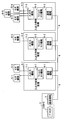
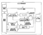
- FIG. 1 is a block diagram illustrating an overall configuration of a controller system according to Embodiment 1.
- FIG. 1 is a block diagram illustrating a configuration of an input / output control device according to a first embodiment.
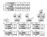
- FIG. 6 is a diagram showing parameters stored in a one-shot timer control register according to the first embodiment.
- FIG. 6 is a diagram for explaining processing of the controller system according to the first embodiment.
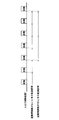
- 3 is a timing chart for explaining processing of the controller system according to the first embodiment. 3 is a flowchart showing processing of the input / output control device according to the first embodiment.
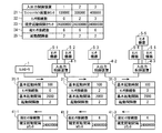
- FIG. 4 is a block diagram illustrating a configuration of an input / output control device according to a second embodiment.
- FIG. 6 is a diagram for explaining processing of a controller system according to Embodiment 2.
- FIG. 6 is a flowchart illustrating processing of the input / output control device according to the second embodiment.
- FIG. 10 is a diagram illustrating parameters stored in a one-shot timer control register according to the third embodiment.
- FIG. 10 is a diagram for explaining processing of a controller system according to a third embodiment.
- 10 is a timing chart for explaining processing of the controller system according to the third embodiment.
- 10 is a flowchart illustrating processing of the input / output control device according to the third embodiment.
- FIG. 15 is a diagram illustrating parameters stored in a one-shot timer control register according to the fourth embodiment.
- FIG. 10 is a diagram for explaining processing of a controller system according to a fourth embodiment. 10 is a timing chart for explaining processing of the controller system according to the fourth embodiment. It is a figure which shows the overlap mode starting space
- FIG. 10 is a flowchart illustrating processing of the input / output control device according to the fourth embodiment.
- FIG. 10 is a block diagram illustrating a configuration of an input / output control device according to a fifth embodiment.
- FIG. 16 is a diagram illustrating parameters stored in a one-shot timer control register according to the fifth embodiment.
- FIG. 10 is a diagram for explaining processing of a controller system according to a fifth embodiment.
- 10 is a timing chart for explaining processing of the controller system according to the fifth embodiment.
- 10 is a flowchart illustrating processing of the input / output control device according to the fifth embodiment.
- 10 is a flowchart illustrating processing of the input / output control device according to the fifth embodiment.
- FIG. 20 is a diagram illustrating parameters stored in a one-shot timer control register according to a sixth embodiment.
- FIG. 10 is a diagram for explaining processing of a controller system according to a sixth embodiment.
- 14 is a flowchart illustrating processing of the input / output control device according to the sixth embodiment.
- FIG. 1 is a block diagram showing an overall configuration of a controller system according to Embodiment 1 of the present invention.
- the overall configuration of a controller system according to another embodiment described later is the same as the overall configuration of the controller system of FIG.
- the input / output control device 4-1 includes a controller 1 and input / output control devices 4-1, 4-2 and 4-3.
- input / output control device 4-1 to the input / output control device 4-3 may be simply referred to as “input / output control device 4”.
- the plurality of input / output control devices according to the present invention is not limited to the three input / output control devices 4, and may be two or more input / output control devices other than three.
- the controller 1 includes a processor 2 and a communication function 3.
- the processor 2 is composed of, for example, a CPU.
- the communication function 3 can communicate with the input / output control device 4 and here communicates with the input / output control device 4-1.
- the controller 1 is connected via the communication bus 6 so that it can communicate with the input / output control device 4-1.
- the input / output control device 4-1 is connected to the input / output control device 4-2 via the communication bus 6 so that the input / output control device 4-2 can communicate with the input / output control device 4-3.
- the plurality of input / output control devices 4 are connected in series so as to be communicable with the controller 1.
- the input / output control device 4-1 is connected to the sensor devices 5-1 and 5-2
- the input / output control device 4-2 is connected to the sensor device 5-3
- the input / output control device 4- 3 is connected to sensor devices 5-4, 5-5 and 5-6.
- each may be simply referred to as “sensor device 5”.
- the sensor device according to the present invention is not limited to the six sensor devices 5, and may be one or more sensor devices other than six.
- the sensor device 5 inputs / outputs sensor data from / to the outside of the sensor device 5.
- the input / output control device 4 can be connected to the sensor device 5 and inputs / outputs sensor data to / from the connected sensor device 5.
- the input / output control device 4-1 includes an input / output function 7-1, a one-shot timer function 8-1, and a communication function 9-1.
- the input / output control device 4-2 includes an input / output function 7-2, a one-shot timer function 8-2, and a communication function 9-2.
- the input / output control device 4-3 includes an input / output function 4-2. 7-3, a one-shot timer function 8-3, and a communication function 9-3.
- each may be simply referred to as “input / output function 7”.
- the one-shot timer functions 8-1 to 8-3 each may be simply referred to as “one-shot timer function 8”.
- communication function 9 each may be simply referred to as “communication function 9”.
- the input / output function 7 inputs and outputs data such as sensor data with the sensor device 5.
- the one-shot timer function 8 generates an interrupt when the counter counted after obtaining the activation request for the one-shot timer 12 from the controller 1 is equal to the one-shot timer activation counter described later.
- the communication function 9 transmits and receives data such as sensor data to and from the controller 1 and one input / output control device 4 or two input / output control devices 4.
- the one-shot timer 12 is a circuit that outputs a pulse signal for a predetermined time only once after the activation time is set and activated.
- the counter is a register used by software or hardware. Throughout the specification, the counter is a value calculated by counting time based on the frequency of each device. Throughout the specification, values or times that are compared by software or hardware are used to define intervals or times.
- FIG. 2 is a block diagram showing a configuration of the input / output control device 4 according to the first embodiment.
- one input / output control device 4 of interest among the plurality of input / output control devices 4 may be referred to as “own device”.
- the 2 includes a timer generation unit 11, a one-shot timer 12, a one-shot timer interrupt generation unit 13, a one-shot timer control register 14, and an activation counter calculation unit 15.
- the timer generation unit 11 has a common timer generation frequency for each input / output control device, and generates a trigger for periodically incrementing the count.
- the one-shot timer 12 periodically increments the one-shot timer count based on a trigger from the timer generation unit 11 when activated.
- the one-shot timer interrupt generation unit 13 generates a one-shot timer interrupt when the one-shot timer count is equal to the timer activation counter.
- the one-shot timer control register 14 stores parameters for controlling the operation of the input / output control device 4.
- the activation counter calculation unit 15 is the total of the sensor devices 5 that are targets to activate the one-shot timer 12 among the sensor devices 5 connected to the other input / output control devices 4 between the own device and the controller 1.
- the one-shot timer activation counter is calculated based on the number and the unit conversion coefficient obtained by converting the one-shot timer activation time based on the timer generation frequency.
- the calculation result of the activation counter calculation unit 15 is stored in the one-shot timer control register 14.
- the one-shot timer counter is a register indicating the number of times the clock signal has become valid after the one-shot timer is activated.
- the timer activation counter is a register for the one-shot timer to output a pulse signal when equal to the one-shot timer counter.
- the one-shot timer activation time indicates a common interval / time that does not depend on the frequency of the apparatus.
- the one-shot timer activation counter is a register that stores a value calculated using time as a counter based on the frequency of the apparatus.
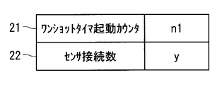
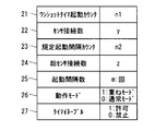
- FIG. 3 is a diagram showing parameters stored in the one-shot timer control register 14 according to the first embodiment.
- the one-shot timer control register 14 stores a timer start counter 21 and a sensor connection number 22 as parameters.
- the timer activation counter 21 is a counter that is compared with the one-shot timer count of the one-shot timer 12 in order to determine whether or not a one-shot timer interrupt should be generated.
- the sensor connection number 22 is the total of the sensor devices 5 that are targets for starting the one-shot timer 12 among the sensor devices 5 connected to the other input / output control devices 4 between the own device and the controller 1. Is a number.
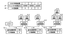
- FIG. 4 is a diagram for explaining processing of the controller system according to the first embodiment.
- the calculation of the following one-shot timer activation counter is performed by the activation counter calculation unit 15 of each of the input / output control devices 4-1 to 4-3.
- Initialization registration data 31-1 which is data for defining parameters of the one-shot timer control register 14 to the input / output control device 4-1.
- Initialization registration data 31-1 includes a basic activation time that is a predetermined time for activating a single one-shot timer 12, and the number of sensor connections.
- the basic activation time of the registration data 31-1 at initialization is “100”, and the number of sensor connections of the registration data 31-1 at initialization is “0”, which is an initial value.
- the input / output control device 4-1 calculates a one-shot timer start counter based on the number of sensor connections.
- the input / output control device 4-1 calculates a value obtained by basic start time + basic start time ⁇ number of connected sensors as a one-shot timer start counter, and the calculated one-shot timer start counter
- the received number of sensor connections is stored in the one-shot timer control register 14.
- the input / output control device 4-1 transmits initialization data 31-2 similar to the initialization data 31-1 to the input / output control device 4-2.
- the basic activation time of the initialization registration data 31-2 is “100”.
- the number of sensor connections in the initialization registration data 31-2 is “0” as the number of sensor connections in the initialization registration data 31-1, and the sensor devices 5-1 and 5 connected to the input / output control device 4-1.
- -2 is "2" with "2" added.
- the input / output control device 4-2 calculates a one-shot timer start counter based on the number of sensor connections.
- the input / output control device 4-2 calculates the one-shot timer start counter in the same manner as the calculation of the one-shot timer start counter by the input / output control device 4-1, and the calculated one-shot timer
- the activation counter and the number of received sensor connections are stored in the one-shot timer control register 14.
- the input / output control device 4-2 transmits initialization data 31-3 similar to the initialization data 31-1 to the input / output control device 4-3.
- the basic activation time of the initialization registration data 31-3 is “100”.
- the number of sensor connections in the registration data 31-3 at initialization is “2” as the number of sensor connections in the registration data 31-2 at initialization, and the “number of sensor connections” in the sensor device 5-3 connected to the input / output control device 4-2. “3” with “1” added.
- the input / output control device 4-3 calculates a one-shot timer start counter based on the number of connected sensors.
- the input / output control device 4-3 calculates the one-shot timer activation counter in the same manner as the calculation of the one-shot timer activation counter by the input / output control device 4-1, and the calculated one-shot timer
- the activation counter and the number of received sensor connections are stored in the one-shot timer control register 14.
- registration data 31-1 to 31-3 at initialization each may be simply referred to as “registration data 31 at initialization”.
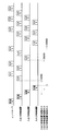
- FIG. 5 is a timing chart showing the timing for transmitting sensor data to the controller 1 by a one-shot timer interrupt in the controller system according to the first embodiment.
- 5 corresponds to the input / output control devices 4-1, 4-2, 4-3 in FIG. 1, and the input / output control device 1 start counter in FIG. This corresponds to the one-shot timer start counter of the input / output control device 4-1.
- 5 corresponds to the initialization registration data 31 described with reference to FIG. 4.
- the sensors 1, 2, 3, 4, 5, and 6 in FIG. It corresponds to the sensor data of 5-2, 5-3, 5-4, 5-5 and 5-6. These notations are used similarly in the subsequent timing charts.
- the initialization registration data 31 from the controller 1 is transmitted to the input / output control devices 4-1, 4-2, 4-3 in order, so that the input / output control device 4
- the one-shot timer start counters are sequentially set in the one-shot timer control registers 14 of -1, 4-2 and 4-3.
- the one-shot timer start counter of the input / output control device 4-1 When the one-shot timer start counter of the input / output control device 4-1 is set, the one-shot timer 12 of the input / output control device 4-1 starts. When the one-shot timer count becomes equal to the one-shot timer start counter (in this example, “100000”) of the input / output control device 4-1, the input / output control device 4-1 The sensor data 5-1 and 5-2 are transmitted to the controller 1 in order.
- the one-shot timer activation counter of the input / output control device 4-2 is set, the one-shot timer 12 of the input / output control device 4-2 is activated.
- the one-shot timer count becomes equal to the one-shot timer start counter (“300000” in this example) of the input / output control device 4-2, the input / output control device 4-2
- the sensor data 5-3 is transmitted to the controller 1 via the input / output control device 4-1.
- the one-shot timer start counter of the input / output control device 4-3 when the one-shot timer start counter of the input / output control device 4-3 is set, the one-shot timer 12 of the input / output control device 4-3 starts.
- the one-shot timer count becomes equal to the one-shot timer start counter (“400000” in this example) of the input / output control device 4-3, the input / output control device 4-3
- the sensor data 5-4, 5-5, and 5-6 are sequentially transmitted to the controller 1 via the input / output control devices 4-1 and 4-2.
- FIG. 6 is a flowchart showing a one-shot timer interrupt generation process in the input / output control device 4 according to the first embodiment. The processing of this flowchart is executed when a trigger is generated by the timer generation unit 11, in other words, when a trigger is received.
- step S1 the input / output control device 4 turns off the one-shot timer interrupt.
- step S2 the input / output control device 4 determines whether or not the one-shot timer 12 is currently activated. If it is determined that it has been started, the process proceeds to step S3. If it is determined that it has been stopped, the process proceeds to step S6.
- step S3 the one-shot timer 12 increments the one-shot timer count.
- step S4 the one-shot timer interrupt generation unit 13 determines whether or not the one-shot timer count is equal to the one-shot timer activation counter. If it is determined that they are equal, the process proceeds to step S5. If it is determined that they are not equal, the process of FIG. 6 ends.
- step S5 the one-shot timer interrupt generator 13 turns on the one-shot timer interrupt and generates a one-shot timer interrupt. Further, the input / output control device 4 stops activation of the one-shot timer 12. Thereafter, the process of FIG. 6 ends.
- step S6 the input / output control device 4 determines whether or not the activation request for the one-shot timer 12, such as the registration data 31 at initialization, has been acquired from the controller 1. If it is determined that it has been acquired, the process proceeds to step S7. If it is determined that it has not been acquired, the process of FIG. 6 ends.
- step S7 the input / output control device 4 resets the one-shot timer count to 0 and activates the one-shot timer 12. Thereafter, the process of FIG. 6 ends.
- each activation counter calculation unit 15 of the plurality of input / output control devices 4 calculates a one-shot timer activation counter based on the number of sensor connections. According to such a configuration, even if the timer is provided in the controller 1 and the controller 1 does not manage the time event queue, that is, does not manage the time for generating an interrupt, the controller 1 Can be obtained. For this reason, the load of the controller 1 can be suppressed. In addition, an improvement in the responsiveness of the controller system can be expected.
- the one-shot timer interrupt generation unit 13 generates a one-shot timer interrupt when the one-shot timer count is equal to the one-shot timer activation counter.
- the present invention is not limited to this example, and the one-shot timer interrupt generation unit 13 may generate a one-shot timer interrupt when the one-shot timer count is equal to or greater than the one-shot timer activation counter.
- the one-shot timer 12 periodically increments the one-shot timer count.
- the present invention is not limited to this example, and the one-shot timer 12 may periodically decrement the one-shot timer count in which the initial value is set to a relatively large value.
- the one-shot timer interrupt generator 13 may generate a one-shot timer interrupt when the difference between the initial value and the one-shot timer count is equal to or greater than the one-shot timer activation counter. That is, the one-shot timer interrupt generation unit 13 may be configured to generate a one-shot timer interrupt based on the one-shot timer count and the one-shot timer activation counter.
- FIG. 7 is a block diagram showing the configuration of the input / output control apparatus according to Embodiment 2 of the present invention.
- the same or similar constituent elements as those in the first embodiment are denoted by the same reference numerals, and different constituent elements will be mainly described.
- the one-shot timer function 8 in FIG. 7 includes a one-shot timer activation interval abnormality management unit 16 and a specified activation interval calculation unit 17 in addition to the one-shot timer function 8 according to the first embodiment in FIG.
- the one-shot timer activation interval abnormality management unit 16 defines the interval between the time when the one-shot timer 12 was activated last time and the time when the one-shot timer 12 is activated next time, that is, the activation interval of the one-shot timer 12. Detects whether or not it is more than the startup interval. Then, the one-shot timer activation interval abnormality management unit 16 notifies the controller 1 of the activation interval abnormality when the activation interval of the one-shot timer 12 is equal to or greater than the specified activation interval.
- the specified activation interval calculation unit 17 is defined based on the total number of sensor devices 5 that are the targets for starting the one-shot timer 12 among all the sensor devices 5 connected to the plurality of input / output control devices 1. Calculate the startup interval counter. The calculation result of the prescribed activation interval calculation unit 17 is stored in the one-shot timer control register 14. The specified activation interval calculation unit 17 is not necessarily provided in each of the plurality of input / output control devices 1, and may be provided in at least one of the plurality of input / output control devices 1.
- FIG. 8 is a diagram showing parameters stored in the one-shot timer control register 14 according to the second embodiment.
- the one-shot timer control register 14 according to the second embodiment stores a specified activation interval counter 23 and a total sensor connection number 24 in addition to the parameters shown in FIG.
- the prescribed activation interval counter 23 is a predefined counter for determining whether or not the activation interval of the one-shot timer 12 is abnormal.
- the total number of sensor connections 24 is the sensor device for which the one-shot timer 12 is activated among all the sensor devices 5-1 to 5-6 connected to the input / output control devices 4-1 to 4-3. Is the total number of That is, the total number of sensor connections 24 is the total number of sensor devices that are targets for starting the one-shot timer 12 among all the sensor devices 5 connected to the controller system.
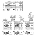
- FIG. 9 is a diagram for explaining processing of the controller system according to the second embodiment.
- the controller 1 transmits initialization data 31-1 to the input / output control device 4-1.
- the initialization registration data 31-1 according to the second embodiment includes a basic activation interval in addition to the initialization registration data 31-1 according to the first embodiment in FIG.
- the initialization registration data 31-2 and 31-3 according to the second embodiment further includes a basic activation interval.
- the basic activation interval of the initialization registration data 31-1 to 31-3 is “2000000”.
- the prescribed activation interval calculation unit 17 calculates a prescribed activation interval counter based on the total number of sensor connections.
- the specified activation interval calculation unit 17 is provided in the input / output control device 4-3 which is a termination device in the column of the input / output control devices 4-1 to 4-3, and the basic activation interval ⁇ A value obtained by the total number of sensor connections ⁇ unit conversion coefficient is calculated as a specified activation interval counter.
- the input / output control device 4-3 stores the calculated total sensor connection number and the specified activation interval counter in the one-shot timer control register 14 of the input / output control device 4-3. Further, the input / output control device 4-3 transmits the initialization return data 41-3 including the total number of sensor connections and the specified activation interval counter to the input / output control device 4-2.
- the input / output control device 4-2 stores the transmitted total number of sensor connections and the specified activation interval counter in the one-shot timer control register 14 of the input / output control device 4-2. Further, the input / output control device 4-2 transmits initialization return data 41-2 including the total number of sensor connections and the specified activation interval counter to the input / output control device 4-1.
- the input / output control device 4-1 stores the transmitted total number of sensor connections and the specified activation interval counter in the one-shot timer control register 14 of the input / output control device 4-1. Further, the input / output control device 4-1 transmits the initialization return data 41-1 including the total number of sensor connections and the prescribed activation interval counter to the controller 1.
- initialization return data 41 when the initialization return data 41-1 to 41-3 are not specified, each may be simply referred to as “initialization return data 41”.
- the one-shot timer activation interval abnormality management unit 16 of the input / output control device 4 notifies the controller 1 of the activation interval abnormality when the one-shot timer count exceeds the specified activation interval counter.
- FIG. 10 is a flowchart showing the calculation processing of the total number of connected sensors and the prescribed activation interval counter in the input / output control device 4 according to the second embodiment.
- step S11 when the input / output control device 4 receives the registration data 31 at initialization including the basic activation time, the number of sensor connections, and the basic activation interval, the input / output control device 4 is connected to the device at the received number of sensor connections.
- a value obtained by adding the number of sensor devices 5 is stored in the one-shot timer control register 14 of the own device as the number of sensor connections of the own device.
- step S12 the input / output control device 4 determines whether or not the own device is a termination device in the row of the plurality of input / output control devices 4. If it is determined that the device is not a terminal device, the process proceeds to step S13. If it is determined that the device is a terminal device, the process proceeds to step S14.
- step S ⁇ b> 13 the input / output control device 4 transmits the initialization registration data 31 including the calculated number of sensor connections and the received basic activation time and basic activation interval to the termination-side input / output control device 4. To do. Thereafter, the process of FIG. 10 ends.
- step S14 since the input / output control device 4 is a termination device, the calculated number of sensor connections is stored in the one-shot timer control register 14 of its own device as the total number of sensor connections. To do.
- the specified activation interval calculation unit 17 multiplies the basic activation interval, the total number of sensor connections, and the unit conversion coefficient, and stores the result in the one-shot timer control register 14 of its own apparatus as a specified activation interval counter.
- step S15 the input / output control device 4 transmits the initialization return data 41 including the total number of connected sensors and the specified activation interval counter to the input / output control device 4 on the controller 1 side or the controller 1. Thereafter, the process of FIG. 10 ends.
- the specified activation interval counter is calculated based on the total number of sensor connections. According to such a configuration, even if the total number of sensor connections is increased or decreased, the specified activation interval counter can be appropriately changed. As a result, it is possible to appropriately detect the activation interval abnormality.
- Embodiment 3 The configuration of the input / output control device according to Embodiment 3 of the present invention is the same as the configuration of the input / output control device according to Embodiment 2 of FIG.
- constituent elements that are the same as or similar to those in the second embodiment are denoted by the same reference numerals, and different constituent elements are mainly described.
- the one-shot timer activation interval abnormality management unit 16 determines whether or not the unit interval counter whose unit is a predetermined number of activation intervals of the one-shot timer 12 is equal to or greater than a specified activation interval counter. Is detected. Then, the one-shot timer activation interval abnormality management unit 16 notifies the controller 1 of the activation interval abnormality when the unit interval counter of the one-shot timer 12 is greater than or equal to the specified activation interval counter.
- the specified activation interval calculation unit 17 includes the total number of sensor devices 5 that are to be activated by the one-shot timer 12 among all the sensor devices 5 connected to the plurality of input / output control devices 1 and unit conversion coefficients. And the prescribed activation interval counter is calculated based on the above-described multiple times.
- the specified activation interval calculation unit 17 is not necessarily provided in each of the plurality of input / output control devices 1, and may be provided in at least one of the plurality of input / output control devices 1.
- FIG. 11 is a diagram showing parameters stored in the one-shot timer control register 14 according to the third embodiment.
- the one-shot timer control register 14 according to the third embodiment stores the activation interval number 25 in addition to the parameters shown in FIG.
- the activation interval number 25 indicates the above-described multiple times in the unit interval.
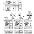
- FIG. 12 is a diagram for explaining processing of the controller system according to the third embodiment.
- the controller 1 transmits initialization data 31-1 to the input / output control device 4-1.
- the initialization registration data 31-1 according to the third embodiment includes the number of activation intervals in addition to the initialization registration data 31-1 according to the second embodiment in FIG.
- the initialization registration data 31-2 and 31-3 according to the third embodiment further includes the number of activation intervals.
- the activation interval number of the registration data 31-1 to 31-3 at initialization is “2”.
- the prescribed activation interval calculation unit 17 calculates a prescribed activation interval counter based on the total sensor connection number and the activation interval number.
- the input / output control device 4 stores the total number of connected sensors and the specified activation interval counter in the one-shot timer control register 14 of its own device. Then, the input / output control device 4 transmits the initialization return data 41 including the total number of sensor connections and the specified activation interval counter to the input / output control device 4 on the controller 1 side or the controller 1.
- FIG. 13 is a timing chart showing an interval for detecting a startup interval abnormality in the controller system according to the third embodiment and an interval for detecting a startup interval abnormality in the controller system according to the second embodiment.
- FIG. 13 shows the input / output control device 4-1, the same applies to the input / output control devices 4-2 and 4-3.
- the monitoring interval when there is no activation interval number in FIG. 13 means a monitoring interval when the activation interval number is 1, and corresponds to the detection interval of the activation interval abnormality in the second embodiment.
- the detection interval of the activation interval abnormality in the second embodiment corresponds to the activation interval for one time of the one-shot timer 12.
- the monitoring section when the number of activation intervals in FIG. 13 is 2 corresponds to the detection interval of the activation interval abnormality in the third embodiment.
- the detection interval of the activation interval abnormality in the third embodiment corresponds to the activation interval of two times of the one-shot timer 12, that is, the activation interval of the activation interval number.
- FIG. 14 is a flowchart showing a detection process of an abnormal start interval in the input / output control device 4 according to the third embodiment. The following description is based on the assumption that the trigger of the timer generation unit 11 has been received and the interrupt handler has already been started.
- step S21 the activation interval timer (not shown) of the input / output control device 4 increments the activation interval timer count.
- step S22 the one-shot timer activation interval abnormality management unit 16 determines whether the activation interval timer count matches the specified activation interval counter. If it is determined that they match, the process proceeds to step S23, and if it is determined that they do not match, the process proceeds to step S24.
- step S23 the one-shot timer activation interval abnormality management unit 16 activates a one-shot timer activation interval abnormality interrupt and notifies the controller 1 of the activation interval abnormality. Thereafter, the process of FIG. 14 ends.
- the one-shot timer activation interval abnormality management unit 16 determines whether or not the activation request for the one-shot timer 12 such as registration data 31 at initialization is acquired from the controller 1. judge. If it is determined that it has been acquired, the process proceeds to step S25. If it is determined that it has not been acquired, the process proceeds to step S26.
- step S25 the one-shot timer activation interval abnormality management unit 16 increments the activation count. Then, the process proceeds to step S26.
- step S26 the one-shot timer activation interval abnormality management unit 16 determines whether or not the activation count matches the activation interval number. If it is determined that they match, the process proceeds to step S27. If it is determined that they do not match, the process of FIG. 14 ends.
- step S27 the one-shot timer activation interval abnormality management unit 16 resets the activation count and the activation interval timer count to zero. Thereafter, the process of FIG. 14 ends.
- the specified activation interval counter is calculated based on the total number of sensor connections, the activation interval number, and the unit conversion coefficient. The effect of can be obtained.
- an activation interval abnormality can be detected.
- Embodiment 4 The configuration of the input / output control device according to Embodiment 4 of the present invention is the same as the configuration of the input / output control device according to Embodiment 2 of FIG.
- constituent elements that are the same as or similar to those in the third embodiment are denoted by the same reference numerals, and different constituent elements are mainly described.
- the one-shot timer activation interval abnormality management unit 16 includes a first mode for detecting an activation interval abnormality starting from one activation of the one-shot timer 12, and the number of activation intervals of the one-shot timer. And a second mode in which an activation interval abnormality is detected starting from the activation.
- the one-shot timer activation interval abnormality management unit 16 selectively implements the first mode and the second mode.
- the first mode will be described as a superposition mode
- the second mode will be described as a normal mode.
- FIG. 15 is a diagram showing parameters stored in the one-shot timer control register 14 according to the fourth embodiment.
- the one-shot timer control register 14 according to the fourth embodiment stores an operation mode 26 in addition to the parameters shown in FIG.
- the operation mode 26 indicates whether the control method for monitoring the activation interval of the one-shot timer is the normal mode or the overlap mode.
- the operation mode 26 is “0”, it may indicate that the control method is the normal mode, and when the operation mode 26 is “1”, the control method is the overlap mode. It is configured.
- FIG. 16 is a diagram for explaining processing of the controller system according to the fourth embodiment.
- the controller 1 transmits initialization data 31-1 to the input / output control device 4-1.
- the initialization registration data 31-1 according to the fourth embodiment includes an operation mode in addition to the initialization registration data 31-1 according to the third embodiment of FIG.
- the initialization registration data 31-2 and 31-3 according to the fourth embodiment further includes an operation mode.
- the operation mode of the registration data 31-1 to 31-3 at initialization is “overlapping mode”.
- the initialization registration data 31 from the controller 1 is sequentially transmitted to the input / output control devices 4-1, 4-2, 4-3, so that the input / output control devices 4-1, 4-2, In the 4-3 one-shot timer control register 14, the “overlapping mode” is set in order.
- FIG. 17 is a timing chart showing the intervals at which the activation interval abnormality is detected in the controller system according to the fourth embodiment.
- FIG. 17 shows the input / output control device 4-1, but the same applies to the input / output control devices 4-2 and 4-3.
- the number of activation intervals is “2”.
- the normal mode starting of the same number of activation intervals as the number of activation intervals of the one-shot timer 12 is used as a starting point, monitoring of the activation interval is started, and detection of an abnormal activation interval is performed.
- the overlap mode monitoring of all the activation intervals is started with one activation of the one-shot timer 12 as a starting point, and the activation interval abnormality is detected.
- FIG. 18 is a diagram showing the overlap mode activation interval management table. This overlap mode activation interval management table stores information for managing all activation intervals using the overlap mode.
- This table has the same number of records as the number of activation intervals.
- the timer number is a number indicating the ID of the record, and numbers are given in the order of 0, 1, 2,.
- the activation interval timer count is incremented to monitor the activation interval, while being reset at activation.
- the reset trigger is data for deciding how many times the activation request is received and resetting the activation interval timer count, and is a variable that is changed as the processing proceeds.
- the specified activation interval counter is the same as described above.
- the number of activation requests is the number of times an activation interval timer (not shown) provided in the input / output control device 4 has been activated so far, and is a variable that is changed as processing proceeds.
- FIG. 19 is a flowchart showing a detection process of a start interval abnormality when the overlap mode is applied in the input / output control device 4 according to the fourth embodiment. The following description is based on the assumption that the trigger of the timer generation unit 11 has been received and the interrupt handler has already been started.
- steps S31 to S38 described below is repeatedly executed by the same number as the number of activation intervals and consequently the number of timer numbers.
- the timer number compared in step S31 is changed so as to increase in order of 0, 1, 2,... Each time the flow of steps S31 to S38 is repeated.
- step S31 the input / output control device 4 determines whether the number of activation requests is larger than the timer number. If it is determined that the number of activation requests is greater than the timer number, the process proceeds to step S32. If it is determined that the number of activation requests is equal to or less than the timer number, the process of FIG. Thus, only when an activation request is received, the process proceeds to step S32 and each timer detects an abnormality.
- step S32 the activation interval timer (not shown) of the input / output control device 4 increments the activation interval timer count.
- step S33 the one-shot timer activation interval abnormality management unit 16 determines whether or not the activation interval timer count matches the specified activation interval counter. If it is determined that they match, the process proceeds to step S34, and if it is determined that they do not match, the process proceeds to step S35.
- step S34 the one-shot timer activation interval abnormality management unit 16 activates a one-shot timer activation interval abnormality interrupt and notifies the controller 1 of the activation interval abnormality. Thereafter, if the number of repetitions of the flow of steps S31 to S38 has not reached the number of activation intervals, the process returns to step S31, and if it has reached the number of activation intervals, the process of FIG.
- the one-shot timer activation interval abnormality management unit 16 determines whether or not the activation request for the one-shot timer 12 such as the registration data 31 at initialization is acquired from the controller 1. judge. If it is determined that it has been acquired, the process proceeds to step S36. If it is determined that it has not been acquired, the process proceeds to step S37.
- step S36 the one-shot timer activation interval abnormality management unit 16 increments the number of activation requests. Then, the process proceeds to step S37.
- step S37 the one-shot timer activation interval abnormality management unit 16 determines whether or not the number of activation requests matches the reset trigger. If it is determined that they match, the process proceeds to step S38. If it is determined that they do not match, the process returns to step S31 if the number of repetitions of the flow of steps S31 to S38 has not reached the number of activation intervals, and if the number of activation intervals has been reached, the process of FIG. finish.
- step S38 the one-shot timer activation interval abnormality management unit 16 resets the activation interval timer count to 0, and adds the activation interval number to the reset trigger. Thereafter, if the number of repetitions of the flow of steps S31 to S38 has not reached the number of activation intervals, the process returns to step S31, and if it has reached the number of activation intervals, the process of FIG.
- the overlap mode in which the activation interval abnormality can be detected every time the one-shot timer 12 is activated, and the activation interval of the one-shot timer 12 The normal mode capable of detecting the activation interval abnormality every number of activations is selectively performed. Thereby, the electric power used in a circuit can be reduced as needed.
- FIG. 20 is a block diagram showing the configuration of the input / output control apparatus according to Embodiment 5 of the present invention.
- constituent elements described in the fifth embodiment constituent elements that are the same as or similar to those in the fourth embodiment are denoted by the same reference numerals, and different constituent elements are mainly described.
- the one-shot timer 12 increments the one-shot timer count. Then, the one-shot timer prohibition / permission unit 18 controls permission / prohibition of increment of the one-shot timer count by controlling activation and stop of the one-shot timer 12.
- the present invention is not limited to this example.
- the one-shot timer 12 decrements, the one-shot timer prohibition / permission unit 18 controls the one-shot timer 12 to start and stop, thereby controlling the one-shot timer count. The decrement permission and prohibition may be controlled.
- the input / output control device 4 detects the start interval abnormality when all of the sensor devices 5 connected to the own device are not the targets for starting the one-shot timer 12. Ban.
- FIG. 21 is a diagram showing parameters stored in the one-shot timer control register 14 according to the fifth embodiment.
- the one-shot timer control register 14 according to the fifth embodiment stores a timer enable 27 in addition to the parameters shown in FIG.
- the timer enable 27 indicates count-up of the one-shot timer 12 for each sensor device 5, that is, permission or prohibition of increment. Here, if the timer enable 27 is “0”, it indicates that activation and increment of the one-shot timer 12 are prohibited. If the timer enable 27 is “1”, activation and increment of the one-shot timer 12 are indicated. Indicates that is allowed.
- FIG. 22 is a diagram for explaining processing of the controller system according to the fifth embodiment.
- the controller 1 transmits the initialization registration data 31-1 to the input / output control device 4-1.
- the initialization registration data 31-1 according to the fifth embodiment includes a timer enable in addition to the initialization registration data 31-1 according to the fourth embodiment in FIG.
- the initialization registration data 31-2 and 31-3 according to the fifth embodiment further includes a timer enable.
- the timer enable of the registration data 31-1 to 31-3 at the time of initialization is “1” for permitting activation of the one-shot timer 12 of the input / output control device 4-1, and the input / output control.
- 3-bit “101” in which “0” prohibiting activation of the one-shot timer 12 of the device 4-2 and “1” permitting activation of the one-shot timer 12 of the input / output control device 4-3 are arranged. It is.
- the input / output control device 4-1 when the initialization registration data 31-1 is transmitted from the controller 1 to the input / output control device 4-1, the input / output control device 4-1 enables the timer enable of the received initialization registration data 31-1. “1” and the number of sensor connections “0” are stored in the one-shot timer control register 14 of the own apparatus. Then, the input / output control device 4-1 transmits the initialization registration data 31-2 to the input / output control device 4-2.
- the sensor devices 5-1 and 5-2 connected to the input / output control device 4-1 are targets for starting the one-shot timer 12, that is, targets for counting by the one-shot timer 12. For this reason, the number of sensor connections in the registration data 31-2 at initialization is obtained by adding “2” of the sensor devices 5-1 and 5-2 to “0” of the number of sensor connections in the registration data 31-1 at initialization. Is "2".
- the input / output control device 4-2 transmits the received initialization registration data 31-2.
- the timer enable “0” is stored in the one-shot timer control register 14 of the device itself.
- the input / output control device 4-2 transmits initialization data 31-3 to the input / output control device 4-3. Since the timer enable of the input / output control device 4-2 is “0”, the sensor device 5-3 connected to the input / output control device 4-2 is not a target for starting the one-shot timer 12. For this reason, the number of sensor connections in the registration data 31-3 at initialization remains “2” as the number of sensor connections in the registration data 31-2 at initialization without adding “1” of the sensor device 5-3. It becomes.
- the input / output control device 4-3 stores the received initialization registration data 31-3.
- the timer enable “1” and the sensor connection number “2” are stored in the one-shot timer control register 14 of the own apparatus. Since the input / output control device 4-3 is a terminal device, the sensor device 5-4 connected to the own device is set to “2” as the number of sensor connections in the received initialization registration data 31-3. “5” obtained by adding “3” of 5-5 and 5-6 is stored in the one-shot timer control register 14 of the own apparatus as the total number of sensor connections. This total sensor connection number is transmitted as the return data 41 at the time of initialization as described in the second embodiment.
- FIG. 23 is a timing chart showing the timing at which sensor data is transmitted to the controller 1 by a one-shot timer interrupt in the controller system according to the fifth embodiment.
- initialization not described in FIG. 5 corresponds to the return data upon initialization in FIG.
- the one-shot timer 12 is not activated for the sensor device 5-3 of the input / output control device 4-2. For this reason, the sensor data of the sensor device 5-3 is not transmitted from the input / output control device 4-2 to the controller 1 via the input / output control device 4-1.
- FIG. 24 is a flowchart showing a one-shot timer interrupt generation process in the input / output control device 4 according to the fifth embodiment.
- the processing of this flowchart is executed when a trigger is generated by the timer generation unit 11, in other words, when a trigger is received.
- the process of FIG. 24 is obtained by adding step S41 and changing step S5 to step S42 in the process of FIG. For this reason, the description of the processes in FIG. 24 other than steps S41 and S42 will be omitted as appropriate.
- step S41 the one-shot timer prohibition and permission unit 18 determines whether or not the timer enable is “1”, that is, whether or not the one-shot timer 12 is allowed to start and increment. If it is determined that the timer enable is “1”, the process proceeds to step S1. If it is determined that the timer enable is “0”, the process of FIG. 24 ends.
- step S4 If it is determined in step S4 from step S1 through steps S2 and S3 that the one-shot timer count is equal to the one-shot timer activation counter, the process proceeds to step S42.
- step S42 the one-shot timer interrupt generator 13 turns on the one-shot timer interrupt and generates a one-shot timer interrupt. Further, the input / output control device 4 stops starting the one-shot timer 12 and resets the one-shot timer count to zero. Thereafter, the process of FIG.
- FIG. 25 is a flowchart showing a start interval abnormality detection process in the input / output control device 4 according to the fifth embodiment. Note that the process of FIG. 25 is obtained by adding step S51 to the process of FIG. 19 of the fourth embodiment using the overlap mode. For this reason, description of processes other than step S51 in the process of FIG. 25 is omitted as appropriate.
- step S51 the input / output control device 4 determines whether or not the timer enable is “1”, that is, whether or not the one-shot timer 12 is allowed to start and increment. If it is determined that the timer enable is “1”, the trigger of the timer generation unit 11 is received and the interrupt handler has already been started, and then the process proceeds to step S31. Thereafter, processing similar to that in the fourth embodiment in FIG. 19 is performed. On the other hand, if it is determined that the timer enable is “0”, the processing in FIG. 25 ends.
- the one-shot timer 12 of only the necessary input / output control device 4 can be started. As a result, unnecessary sensor data need not be collected and transmitted, and the load on the controller 1 can be suppressed.
- Embodiment 6 The configuration of the input / output control device according to Embodiment 6 of the present invention is the same as the configuration of the input / output control device according to Embodiment 5 of FIG.
- the same or similar constituent elements as those in the fifth embodiment are denoted by the same reference numerals, and different constituent elements will be mainly described.
- the input / output control device 4 permits and prohibits the detection of the activation interval abnormality when the sensor device 5 connected to the own device is a target for starting the one-shot timer 12. It is possible to control.
- FIG. 26 is a diagram showing parameters stored in the one-shot timer control register 14 according to the sixth embodiment.
- the one-shot timer control register 14 according to the sixth embodiment stores a start interval enable 28 in addition to the parameters shown in FIG.
- the start interval enable 28 indicates permission and prohibition of detection of the start interval abnormality, and notification of the start interval abnormality to the controller 1 and non-notification.
- the start interval enable 28 is “0”, it indicates that detection of the start interval abnormality is prohibited.
- the start interval enable 28 is “1”, detection of the start interval abnormality is permitted. Indicates that
- FIG. 27 is a diagram for explaining processing of the controller system according to the sixth embodiment.
- the controller 1 transmits initialization data 31-1 to the input / output control device 4-1.
- the initialization registration data 31-1 according to the sixth embodiment includes a start interval enable in addition to the initialization registration data 31-1 according to the fifth embodiment of FIG.
- the initialization registration data 31-2 and 31-3 according to the sixth embodiment further include a start interval enable.
- the activation interval enable of the registration data 31-1 to 31-3 at the time of initialization is “0” prohibiting the detection of abnormality in the activation interval of the input / output control device 4-1, and the input / output control.
- This is a 3-bit “001” in which “1” that permits detection of the startup interval abnormality of the device 4-2 and “1” that allows detection of the startup interval abnormality of the input / output control device 4-3 are arranged. .
- the initialization registration data 31 from the controller 1 is sequentially transmitted to the input / output control devices 4-1, 4-2 and 4-3, thereby controlling the one-shot timer of the input / output control device 4-1.
- “0” is set as the activation interval enable 28 in the register 14
- “1” is set as the activation interval enable 28 in the one-shot timer control register 14 of the input / output control devices 4-2 and 4-3.
- the input / output control device 4-1 does not detect the start interval abnormality because the start interval abnormality is prohibited from being detected by the start interval enable.
- the input / output control device 4-2 is not allowed to detect the start interval abnormality because the start interval is permitted to be detected by the start interval enable but the start of the one-shot timer 12 is prohibited by the timer enable. .
- the input / output control device 4-3 detects the activation interval abnormality because the activation interval is permitted to be detected by the activation interval and the one-shot timer 12 is permitted to be activated by the timer enable.
- FIG. 28 is a flowchart showing detection processing for an abnormal start interval in the input / output control device 4 according to the sixth embodiment.
- the process of FIG. 28 is obtained by adding steps S51 and S61 to the process of FIG. 19 of the fourth embodiment using the overlap mode. For this reason, the description of the processes in FIG. 28 other than steps S51 and S61 will be omitted as appropriate.
- step S51 the input / output control device 4 determines whether or not the timer enable is “1”, that is, whether or not the one-shot timer 12 is allowed to start and increment. If it is determined that the timer enable is “1”, the process proceeds to step S61. If it is determined that the timer enable is “0”, the process of FIG. 28 ends.
- step S61 the input / output control device 4 determines whether or not the activation interval enable is “1”, that is, whether or not detection of the activation interval abnormality is permitted. If it is determined that the activation interval enable is “1”, the trigger of the timer generation unit 11 is received and the interrupt handler has already been activated, and then the process proceeds to step S31. Thereafter, processing similar to that in the fourth embodiment in FIG. 19 is performed. On the other hand, if it is determined that the activation interval enable is “0”, the processing in FIG. 28 ends.
- the controller system even if the sensor device 5 is a target for starting the one-shot timer 12, it controls the permission and prohibition of detection of the start interval abnormality. Thus, it is possible to detect the start interval abnormality of only the necessary input / output control device 4. As a result, it is possible to further enhance the effect that it is not necessary to detect and transmit an unnecessary activation interval abnormality, and the load on the controller 1 can be suppressed.
- controller 4-1 to 4-3 input / output control device, 5-1 to 5-6 sensor device, 12 one-shot timer, 13 one-shot timer interrupt generation unit, 15 activation counter calculation unit, 16 one-shot timer activation interval Anomaly management part, 17 Specified start interval calculation part, 18 One shot timer prohibition and permission part.
Landscapes
- Engineering & Computer Science (AREA)
- Physics & Mathematics (AREA)
- General Physics & Mathematics (AREA)
- Theoretical Computer Science (AREA)
- General Engineering & Computer Science (AREA)
- Automation & Control Theory (AREA)
- Software Systems (AREA)
- Computer Hardware Design (AREA)
- Programmable Controllers (AREA)
- Debugging And Monitoring (AREA)
Abstract
コントローラの負荷を抑制可能な技術を提供することを目的とする。コントローラシステムは、コントローラと、コントローラと通信可能に直列接続され、それぞれがセンサ機器と接続可能な複数の入出力制御装置とを備える。複数の入出力制御装置のそれぞれは、自入出力制御装置とコントローラとの間の他の入出力制御装置に接続されたセンサ機器のうち、ワンショットタイマを起動させる対象となっているセンサ機器の合計数に基づいて、ワンショットタイマ起動カウンタを算出する。
Description
本発明は、コントローラと、それぞれがセンサ機器と接続可能な複数の入出力制御装置とを備えるコントローラシステムに関する。
従来、周期割込み発生回路は、一定周期でプロセッサへハードウェアの周期割込み信号を出力する。プロセッサ内の制御プログラムは、周期割込み信号により起動されるタイマ割込みルーチンのタイマ処理により、制御プログラムが持つタイマを加算または減算し、加算値または減算値により所定の制御を起動する。また、プロセッサ内の制御プログラムは、ハードウェア周期割込み発生回路の故障によるカウンタ加算または減算及び停止を監視し、監視結果に基づいて障害を検出する。このような技術は、例えば特許文献1に開示されている。
また、CPU(Central Processing Unit)と、このCPUに対して周期性の割込み信号を発生する割込み信号発生回路とを含むシステムにおいて、クロックパルスのカウントが、前記割込み信号発生回路から発生された割込み信号においてリセットされる。そして、リセットされずにカウント値が特定値に達したときにCPUへ割込み信号を出力し、カウンタのリセット前の値が正常値か異常値かを判別することで割込み発生回路の異常を検出する。このような技術は、例えば特許文献2に開示されている。
また、CPUに対して、割込み信号を出力する割込み回路を有する割込み信号監視回路において、計時手段により設定された監視時間内に発生した割込み信号の発生回数を計数し、その計数値が所定値以上である場合にCPUに割込み信号が異常であることを通知する。このような技術は、例えば特許文献3に開示されている。
上記技術においては、一定周期でCPUへ割込みを発生させ、割込みによって起動したプログラム内でカウンタを増減したり、割込みの発生回数が正常であるか異常であるかの判断を行ったりしている。しかしながら、このような構成においては、一定周期の割込みを管理する際、OS(Operating system)が管理するタイムイベントキューを探索し、特定タイミングでタイマ間隔算出や異常報告処理を起動する必要がある。このため、一定周期ごとに起動検出及びタイムアウト検出を行うためのキュー探索が必要となり、CPU、ひいてはCPUを備えるコントローラの負荷が増加する課題がある。
そこで、本発明は、上記のような問題点を鑑みてなされたものであり、コントローラの負荷を抑制可能な技術を提供することを目的とする。
本発明に係るコントローラシステムは、コントローラと、前記コントローラと通信可能に直列接続され、それぞれがセンサ機器と接続可能な複数の入出力制御装置とを備える。前記複数の入出力制御装置のそれぞれは、定期的にワンショットタイマカウントをインクリメントまたはデクリメントするワンショットタイマと、前記ワンショットタイマカウントとワンショットタイマ起動カウンタとに基づいて、ワンショットタイマ割込みを発生させるワンショットタイマ割込み発生部とを備える。前記複数の入出力制御装置のそれぞれは、自入出力制御装置と前記コントローラとの間の他の入出力制御装置に接続された前記センサ機器のうち、前記ワンショットタイマを起動させる対象となっている前記センサ機器の合計数に基づいて、前記ワンショットタイマ起動カウンタを算出する起動カウンタ算出部を備える。
本発明によれば、複数の入出力制御装置のそれぞれは、自入出力制御装置とコントローラとの間の他の入出力制御装置に接続されたセンサ機器のうち、ワンショットタイマを起動させる対象となっているセンサ機器の合計数に基づいて、ワンショットタイマ起動カウンタを算出する。これにより、コントローラの負荷を抑制することができる。
本発明の目的、特徴、態様及び利点は、以下の詳細な説明と添付図面とによって、より明白となる。
<実施の形態1>
図1は、本発明の実施の形態1に係るコントローラシステムの全体構成を示すブロック図である。なお、後述される他の実施の形態に係るコントローラシステムの全体構成も、図1のコントローラシステムの全体構成と同様である。
図1は、本発明の実施の形態1に係るコントローラシステムの全体構成を示すブロック図である。なお、後述される他の実施の形態に係るコントローラシステムの全体構成も、図1のコントローラシステムの全体構成と同様である。
図1のコントローラシステムは、コントローラ1と、入出力制御装置4-1,4-2,4-3とを備える。以下の説明では、入出力制御装置4-1~入出力制御装置4-3を特定しない場合には、それぞれを単に「入出力制御装置4」と記すこともある。なお、本発明に係る複数の入出力制御装置は、3つの入出力制御装置4に限ったものではなく、3つ以外の2つ以上の入出力制御装置であってもよい。
コントローラ1は、プロセッサ2と、通信機能3とを備えている。プロセッサ2は、例えばCPUなどから構成される。通信機能3は、入出力制御装置4と通信を行うことが可能となっており、ここでは入出力制御装置4-1と通信を行う。
コントローラ1は、入出力制御装置4-1と通信可能に通信バス6を介して接続されている。また、入出力制御装置4-1は、入出力制御装置4-2と通信可能に通信バス6を介して接続され、入出力制御装置4-2は、入出力制御装置4-3と通信可能に通信バス6を介して接続されている。このように、複数の入出力制御装置4が、コントローラ1と通信可能に直列接続されている。
図1の例では、入出力制御装置4-1はセンサ機器5-1,5-2と接続され、入出力制御装置4-2はセンサ機器5-3と接続され、入出力制御装置4-3はセンサ機器5-4,5-5,5-6と接続されている。以下の説明では、センサ機器5-1~5-6を特定しない場合には、それぞれを単に「センサ機器5」と記すこともある。なお、本発明に係るセンサ機器は、6つのセンサ機器5に限ったものではなく、6つ以外の1つ以上のセンサ機器であってもよい。
センサ機器5は、センサ機器5の外部とセンサデータの入出力を行う。以上のように、入出力制御装置4は、センサ機器5と接続可能となっており、接続されたセンサ機器5とセンサデータの入出力を行う。
入出力制御装置4-1は、入出力機能7-1と、ワンショットタイマ機能8-1と、通信機能9-1とを備える。同様に、入出力制御装置4-2は、入出力機能7-2と、ワンショットタイマ機能8-2と、通信機能9-2とを備え、入出力制御装置4-3は、入出力機能7-3と、ワンショットタイマ機能8-3と、通信機能9-3とを備える。
なお、以下の説明では、入出力機能7-1~7-3を特定しない場合には、それぞれを単に「入出力機能7」と記すこともある。ワンショットタイマ機能8-1~8-3を特定しない場合には、それぞれを単に「ワンショットタイマ機能8」と記すこともある。通信機能9-1~9-3を特定しない場合には、それぞれを単に「通信機能9」と記すこともある。
入出力機能7は、センサ機器5とセンサデータなどのデータを入出力する。ワンショットタイマ機能8は、コントローラ1からワンショットタイマ12の起動要求を取得してからカウントしたカウンタが、後述するワンショットタイマ起動カウンタと等しい場合に割込みを発生させる。通信機能9は、センサデータなどのデータを、コントローラ1及び1つの入出力制御装置4、または、2つの入出力制御装置4などと送受信する。
ここで、ワンショットタイマ12とは、起動時刻を設定して起動した後、1回だけ一定時間のパルス信号を出力する回路のことである。また、カウンタとは、ソフトウェアまたはハードウェアで使用するレジスタである。明細書の全文を通じて、カウンタは、機器ごとの周波数に基づいて時間をカウントして算出した値である。また明細書の全文を通じて、ソフトウェアまたはハードウェアで比較する値または時間は、間隔または時刻を定義するものとして使用している。
図2は、本実施の形態1に係る入出力制御装置4の構成を示すブロック図である。なお、以下の説明において、複数の入出力制御装置4のうち着目している1つの入出力制御装置4を「自装置」と記すこともある。
図2のワンショットタイマ機能8は、タイマ生成部11と、ワンショットタイマ12と、ワンショットタイマ割込み発生部13と、ワンショットタイマ制御レジスタ14と、起動カウンタ算出部15とを備える。
タイマ生成部11は、各入出力制御装置で共通のタイマ生成用周波数を持ち、定期的にカウントをインクリメントするトリガを生成する。ワンショットタイマ12は、起動されている場合に、タイマ生成部11からのトリガに基づいて、定期的にワンショットタイマカウントをインクリメントする。ワンショットタイマ割込み発生部13は、ワンショットタイマカウントが、タイマ起動カウンタと等しい場合に、ワンショットタイマ割込みを発生させる。ワンショットタイマ制御レジスタ14は、入出力制御装置4の動作を制御するパラメータを格納する。起動カウンタ算出部15は、自装置とコントローラ1との間の他の入出力制御装置4に接続されたセンサ機器5のうち、ワンショットタイマ12を起動させる対象となっているセンサ機器5の合計数と、ワンショットタイマ起動時間をタイマ生成用周波数に基づき変換した単位変換係数とに基づいて、ワンショットタイマ起動カウンタを算出する。起動カウンタ算出部15の算出結果は、ワンショットタイマ制御レジスタ14に格納される。
ここで、ワンショットタイマカウンタとは、ワンショットタイマ起動後にクロック信号が有効になった回数を示すレジスタのことである。また、タイマ起動カウンタとは、ワンショットタイマカウンタと比較し、等しいときにワンショットタイマがパルス信号を出力するためのレジスタのことである。さらに、ワンショットタイマ起動時間とは、装置の周波数に依存しない共通の間隔・時刻を示すものである。また、ワンショットタイマ起動カウンタとは、装置の周波数に基づいて時間をカウンタとして算出した値を格納するレジスタのことである。
図3は、本実施の形態1に係るワンショットタイマ制御レジスタ14に格納されたパラメータを示す図である。ワンショットタイマ制御レジスタ14は、パラメータとして、タイマ起動カウンタ21と、センサ接続数22とを格納している。
タイマ起動カウンタ21は、ワンショットタイマ割込みを発生すべきか否かを判定するために、ワンショットタイマ12のワンショットタイマカウントと比較されるカウンタである。センサ接続数22は、自装置とコントローラ1との間の、他の入出力制御装置4に接続されたセンサ機器5のうち、ワンショットタイマ12を起動させる対象となっているセンサ機器5の合計数である。
図4は、本実施の形態1に係るコントローラシステムの処理を説明するための図である。なお、下記のワンショットタイマ起動カウンタの算出は、入出力制御装置4-1~4-3のそれぞれの起動カウンタ算出部15などによって行われる。
コントローラ1は、ワンショットタイマ制御レジスタ14のパラメータを規定するためのデータである初期化時登録データ31-1を、入出力制御装置4-1に送信する。本実施の形態1に係る初期化時登録データ31-1は、単一のワンショットタイマ12を起動するための予め定められた時間である基本起動時間と、センサ接続数とを含んでいる。図4の例では、初期化時登録データ31-1の基本起動時間は「100」であり、初期化時登録データ31-1のセンサ接続数は初期値の「0」である。
入出力制御装置4-1は、センサ接続数に基づいてワンショットタイマ起動カウンタを算出する。本実施の形態1では、入出力制御装置4-1が、基本起動時間+基本起動時間×センサ接続数によって得られる値を、ワンショットタイマ起動カウンタとして算出し、算出されたワンショットタイマ起動カウンタ及び受信したセンサ接続数をワンショットタイマ制御レジスタ14に格納する。図4の例では、ワンショットタイマ起動時間がミリ秒で定義され、タイマ生成用周波数が1MHzのとき、タイマは1マイクロ秒ごとにカウントアップされるため、入出力制御装置4-1のワンショットタイマ起動カウンタは、「100000(=(100+100×0)×1000)」となる。
入出力制御装置4-1は、初期化時登録データ31-1と同様の初期化時登録データ31-2を、入出力制御装置4-2に送信する。初期化時登録データ31-2の基本起動時間は「100」である。初期化時登録データ31-2のセンサ接続数は、初期化時登録データ31-1のセンサ接続数の「0」に、入出力制御装置4-1に接続されたセンサ機器5-1,5-2の「2」が加えられた「2」である。
入出力制御装置4-2は、センサ接続数に基づいてワンショットタイマ起動カウンタを算出する。本実施の形態1では、入出力制御装置4-2が、入出力制御装置4-1によるワンショットタイマ起動カウンタの算出と同様に、ワンショットタイマ起動カウンタを算出し、算出されたワンショットタイマ起動カウンタ及び受信したセンサ接続数をワンショットタイマ制御レジスタ14に格納する。図4の例では、入出力制御装置4-2のワンショットタイマ起動カウンタは、「300000(=(100+100×2)×1000」となる。
入出力制御装置4-2は、初期化時登録データ31-1と同様の初期化時登録データ31-3を、入出力制御装置4-3に送信する。初期化時登録データ31-3の基本起動時間は「100」である。初期化時登録データ31-3のセンサ接続数は、初期化時登録データ31-2のセンサ接続数の「2」に、入出力制御装置4-2に接続されたセンサ機器5-3の「1」が加えられた「3」である。
入出力制御装置4-3は、センサ接続数に基づいてワンショットタイマ起動カウンタを算出する。本実施の形態1では、入出力制御装置4-3が、入出力制御装置4-1によるワンショットタイマ起動カウンタの算出と同様に、ワンショットタイマ起動カウンタを算出し、算出されたワンショットタイマ起動カウンタ及び受信したセンサ接続数をワンショットタイマ制御レジスタ14に格納する。図4の例では、入出力制御装置4-3のワンショットタイマ起動カウンタは、「400000(=(100+100×3)×1000)」となる。
なお、以下の説明では、初期化時登録データ31-1~31-3を特定しない場合には、それぞれを単に「初期化時登録データ31」と記すこともある。
図5は、本実施の形態1に係るコントローラシステムにおいて、ワンショットタイマ割込みによって、コントローラ1へセンサデータを送信するタイミングを示すタイミングチャートである。
なお、図5の入出力制御装置1,2,3は、図1の入出力制御装置4-1,4-2,4-3に対応し、図5の入出力制御装置1起動カウンタなどは、入出力制御装置4-1のワンショットタイマ起動カウンタなどに対応する。また、図5の初期化は、図4で説明した初期化時登録データ31に対応し、図5のセンサ1,2,3,4,5,6は、図1のセンサ機器5-1,5-2,5-3,5-4,5-5,5-6のセンサデータに対応する。これらの表記は、以降のタイミングチャートにおいて同様に用いられる。
さて、図4で説明したように、コントローラ1からの初期化時登録データ31が、入出力制御装置4-1,4-2,4-3に順に送信されることによって、入出力制御装置4-1,4-2,4-3のワンショットタイマ制御レジスタ14にてワンショットタイマ起動カウンタが順に設定される。
入出力制御装置4-1のワンショットタイマ起動カウンタが設定された際に、入出力制御装置4-1のワンショットタイマ12が起動する。そして、ワンショットタイマカウントが、入出力制御装置4-1のワンショットタイマ起動カウンタ(この例では「100000」)と等しくなった場合に、入出力制御装置4-1は、接続されたセンサ機器5-1,5-2のセンサデータを順に、コントローラ1に送信する。
同様に、入出力制御装置4-2のワンショットタイマ起動カウンタが設定された際に、入出力制御装置4-2のワンショットタイマ12が起動する。そして、ワンショットタイマカウントが、入出力制御装置4-2のワンショットタイマ起動カウンタ(この例では「300000」)と等しくなった場合に、入出力制御装置4-2は、接続されたセンサ機器5-3のセンサデータを、入出力制御装置4-1を介してコントローラ1に送信する。
同様に、入出力制御装置4-3のワンショットタイマ起動カウンタが設定された際に、入出力制御装置4-3のワンショットタイマ12が起動する。そして、ワンショットタイマカウントが、入出力制御装置4-3のワンショットタイマ起動カウンタ(この例では「400000」)と等しくなった場合に、入出力制御装置4-3は、接続されたセンサ機器5-4,5-5,5-6のセンサデータを順に、入出力制御装置4-1,4-2を介してコントローラ1に送信する。
図6は、本実施の形態1に係る入出力制御装置4における、ワンショットタイマ割込み発生処理を示すフローチャートである。本フローチャートの処理は、タイマ生成部11でトリガが生成された場合、換言すればトリガが受信された場合に実行される。
最初にステップS1にて、入出力制御装置4は、ワンショットタイマ割込みをオフ状態にする。
ステップS2にて、入出力制御装置4は、現時点でワンショットタイマ12が起動しているか否かを判定する。起動していると判定された場合には処理がステップS3に進み、停止していると判定された場合には処理がステップS6に進む。
ステップS3にて、ワンショットタイマ12は、ワンショットタイマカウントをインクリメントする。
ステップS4にて、ワンショットタイマ割込み発生部13は、ワンショットタイマカウントがワンショットタイマ起動カウンタと等しいか否かを判定する。等しいと判定された場合には処理がステップS5に進み、等しくないと判定された場合には図6の処理が終了する。
ステップS5にて、ワンショットタイマ割込み発生部13は、ワンショットタイマ割込みをオン状態にし、ワンショットタイマ割込みを発生させる。また、入出力制御装置4は、ワンショットタイマ12の起動を停止する。その後、図6の処理が終了する。
ステップS2からステップS6に処理が進んだ場合、入出力制御装置4は、コントローラ1から、ワンショットタイマ12の起動要求、例えば初期化時登録データ31などを取得したか否かを判定する。取得したと判定された場合には処理がステップS7に進み、取得していないと判定された場合には図6の処理が終了する。
ステップS7にて、入出力制御装置4は、ワンショットタイマカウントをリセットして0にするとともに、ワンショットタイマ12を起動させる。その後、図6の処理が終了する。
以上のような本実施の形態1に係るコントローラシステムによれば、複数の入出力制御装置4のそれぞれの起動カウンタ算出部15が、センサ接続数に基づいて、ワンショットタイマ起動カウンタを算出する。このような構成によれば、コントローラ1内にタイマを設けて、コントローラ1が、タイムイベントキューの管理、つまり割込み発生のための時間の管理を行わなくても、コントローラ1は、時分割でデータを取得することが可能となる。このため、コントローラ1の負荷を抑制することができる。また、コントローラシステムの応答性の向上化も期待できる。
なお、以上の説明では、ワンショットタイマ割込み発生部13は、ワンショットタイマカウントがワンショットタイマ起動カウンタと等しい場合に、ワンショットタイマ割込みを発生させた。しかしこの例に限ったものではなく、ワンショットタイマ割込み発生部13は、ワンショットタイマカウントがワンショットタイマ起動カウンタ以上である場合に、ワンショットタイマ割込みを発生させてもよい。
また、以上の説明では、ワンショットタイマ12は、定期的にワンショットタイマカウントをインクリメントした。しかしこの例に限ったものではなく、ワンショットタイマ12は、比較的大きな値に初期値が設定されたワンショットタイマカウントを定期的にデクリメントしてもよい。そして、ワンショットタイマ割込み発生部13は、初期値とワンショットタイマカウントとの差が、ワンショットタイマ起動カウンタ以上である場合に、ワンショットタイマ割込みを発生させてもよい。つまり、ワンショットタイマ割込み発生部13は、ワンショットタイマカウントとワンショットタイマ起動カウンタとに基づいて、ワンショットタイマ割込みを発生させるように構成されてもよい。
<実施の形態2>
図7は、本発明の実施の形態2に係る入出力制御装置の構成を示すブロック図である。以下、本実施の形態2で説明する構成要素のうち、実施の形態1と同じまたは類似する構成要素については同じ参照符号を付し、異なる構成要素について主に説明する。
図7は、本発明の実施の形態2に係る入出力制御装置の構成を示すブロック図である。以下、本実施の形態2で説明する構成要素のうち、実施の形態1と同じまたは類似する構成要素については同じ参照符号を付し、異なる構成要素について主に説明する。
図7のワンショットタイマ機能8は、図2の実施の形態1に係るワンショットタイマ機能8に加えて、ワンショットタイマ起動間隔異常管理部16と、規定起動間隔算出部17とを備える。
本実施の形態2に係るワンショットタイマ起動間隔異常管理部16は、ワンショットタイマ12が前回起動された時刻と次回起動される時刻との間隔、つまりワンショットタイマ12の起動の間隔が、規定起動間隔以上か否かを検出する。そして、ワンショットタイマ起動間隔異常管理部16は、ワンショットタイマ12の起動の間隔が、規定起動間隔以上である場合に起動間隔異常をコントローラ1に通知する。
規定起動間隔算出部17は、複数の入出力制御装置1に接続された全てのセンサ機器5のうち、ワンショットタイマ12を起動させる対象となっているセンサ機器5の合計数に基づいて、規定起動間隔カウンタを算出する。規定起動間隔算出部17の算出結果は、ワンショットタイマ制御レジスタ14に格納される。なお、規定起動間隔算出部17は、複数の入出力制御装置1のそれぞれに備えられる必要はなく、複数の入出力制御装置1の少なくともいずれか1つに備えられればよい。
図8は、本実施の形態2に係るワンショットタイマ制御レジスタ14に格納されたパラメータを示す図である。本実施の形態2に係るワンショットタイマ制御レジスタ14は、図3のパラメータに加えて、規定起動間隔カウンタ23と、総センサ接続数24とを格納している。
規定起動間隔カウンタ23は、ワンショットタイマ12の起動の間隔が異常か否かを判定するための予め規定されたカウンタである。総センサ接続数24は、入出力制御装置4-1~4-3に接続された全てのセンサ機器5-1~5-6のうち、ワンショットタイマ12を起動させる対象となっているセンサ機器の合計数である。つまり、総センサ接続数24は、コントローラシステムに接続されている全てのセンサ機器5のうち、ワンショットタイマ12を起動させる対象となっているセンサ機器の合計数である。
図9は、本実施の形態2に係るコントローラシステムの処理を説明するための図である。
コントローラ1は、実施の形態1と同様に、初期化時登録データ31-1を入出力制御装置4-1に送信する。ただし、本実施の形態2に係る初期化時登録データ31-1は、図4の実施の形態1に係る初期化時登録データ31-1に加えて、基本起動間隔を含んでいる。同様に、本実施の形態2に係る初期化時登録データ31-2,31-3は、基本起動間隔をさらに含んでいる。なお、図9の例では、初期化時登録データ31-1~31-3の基本起動間隔は「2000000」である。
規定起動間隔算出部17は、総センサ接続数に基づいて、規定起動間隔カウンタを算出する。本実施の形態2では、規定起動間隔算出部17が、入出力制御装置4-1~4-3の列における終端装置である入出力制御装置4-3に備えられており、基本起動間隔×総センサ接続数×単位変換係数によって得られる値を規定起動間隔カウンタとして算出する。
図9の例では、入出力制御装置4-3は、初期化時登録データ31-3のセンサ接続数の「3」に、入出力制御装置4-3に接続されたセンサ機器5-4,5-5,5-6の「3」を加えた「6」を、総センサ接続数として算出する。そして、規定起動間隔算出部17は、「12000000(=(2000×6)×1000)」を、規定起動間隔カウンタとして算出する。
入出力制御装置4-3は、算出された総センサ接続数及び規定起動間隔カウンタを、入出力制御装置4-3のワンショットタイマ制御レジスタ14に格納する。また、入出力制御装置4-3は、総センサ接続数及び規定起動間隔カウンタを含む初期化時返送データ41-3を、入出力制御装置4-2に送信する。
入出力制御装置4-2は、送信された総センサ接続数及び規定起動間隔カウンタを、入出力制御装置4-2のワンショットタイマ制御レジスタ14に格納する。また、入出力制御装置4-2は、総センサ接続数及び規定起動間隔カウンタを含む初期化時返送データ41-2を、入出力制御装置4-1に送信する。
入出力制御装置4-1は、送信された総センサ接続数及び規定起動間隔カウンタを、入出力制御装置4-1のワンショットタイマ制御レジスタ14に格納する。また、入出力制御装置4-1は、総センサ接続数及び規定起動間隔カウンタを含む初期化時返送データ41-1を、コントローラ1に送信する。
なお、以下の説明では、初期化時返送データ41-1~41-3を特定しない場合には、それぞれを単に「初期化時返送データ41」と記すこともある。
その後、入出力制御装置4のワンショットタイマ起動間隔異常管理部16は、ワンショットタイマカウントが規定起動間隔カウンタ以上になったときにコントローラ1に起動間隔異常を通知する。
図10は、本実施の形態2に係る入出力制御装置4における、総センサ接続数及び規定起動間隔カウンタの算出処理などを示すフローチャートである。
最初にステップS11にて、入出力制御装置4は、基本起動時間、センサ接続数及び基本起動間隔を含む初期化時登録データ31を受信すると、受信したセンサ接続数に、自装置に接続されたセンサ機器5の数を加えた値を、自装置のセンサ接続数として自装置のワンショットタイマ制御レジスタ14に格納する。
ステップS12にて、入出力制御装置4は、自装置が、複数の入出力制御装置4の列における終端装置であるか否かを判定する。終端装置ではないと判定された場合には処理がステップS13に進み、終端装置であると判定された場合には処理がステップS14に進む。
ステップS13にて、入出力制御装置4は、算出されたセンサ接続数と、受信した基本起動時間及び基本起動間隔とを含む初期化時登録データ31を、終端側の入出力制御装置4に送信する。その後、図10の処理が終了する。
ステップS12からステップS14に処理が進んだ場合、入出力制御装置4は、終端装置であることから、算出されたセンサ接続数を、総センサ接続数として自装置のワンショットタイマ制御レジスタ14に格納する。そして、規定起動間隔算出部17は、基本起動間隔と総センサ接続数と単位変換係数との乗算を行い、その結果を規定起動間隔カウンタとして自装置のワンショットタイマ制御レジスタ14に格納する。
ステップS15にて、入出力制御装置4は、総センサ接続数及び規定起動間隔カウンタを含む初期化時返送データ41を、コントローラ1側の入出力制御装置4、または、コントローラ1に送信する。その後、図10の処理が終了する。
以上のような本実施の形態2に係るコントローラシステムによれば、総センサ接続数に基づいて、規定起動間隔カウンタが算出される。このような構成によれば、総センサ接続数が増減した場合であっても、規定起動間隔カウンタを適切に変更することができる。これにより、起動間隔異常を適切に検出することができる。
<実施の形態3>
本発明の実施の形態3に係る入出力制御装置の構成は、図7の実施の形態2に係る入出力制御装置の構成と同様である。以下、本実施の形態3で説明する構成要素のうち、実施の形態2と同じまたは類似する構成要素については同じ参照符号を付し、異なる構成要素について主に説明する。
本発明の実施の形態3に係る入出力制御装置の構成は、図7の実施の形態2に係る入出力制御装置の構成と同様である。以下、本実施の形態3で説明する構成要素のうち、実施の形態2と同じまたは類似する構成要素については同じ参照符号を付し、異なる構成要素について主に説明する。
本実施の形態3に係るワンショットタイマ起動間隔異常管理部16は、ワンショットタイマ12の予め定められた複数回の起動の間隔を単位とする単位間隔カウンタが、規定起動間隔カウンタ以上か否かを検出する。そして、ワンショットタイマ起動間隔異常管理部16は、ワンショットタイマ12の単位間隔カウンタが、規定起動間隔カウンタ以上である場合に起動間隔異常をコントローラ1に通知する。
規定起動間隔算出部17は、複数の入出力制御装置1に接続された全てのセンサ機器5のうち、ワンショットタイマ12を起動させる対象となっているセンサ機器5の合計数と、単位変換係数と、上述の複数回とに基づいて、規定起動間隔カウンタを算出する。なお、規定起動間隔算出部17は、複数の入出力制御装置1のそれぞれに備えられる必要はなく、複数の入出力制御装置1の少なくともいずれか1つに備えられればよい。
図11は、本実施の形態3に係るワンショットタイマ制御レジスタ14に格納されたパラメータを示す図である。本実施の形態3に係るワンショットタイマ制御レジスタ14は、図8のパラメータに加えて、起動間隔数25を格納している。起動間隔数25は、単位間隔における上述の複数回を示す。
図12は、本実施の形態3に係るコントローラシステムの処理を説明するための図である。
コントローラ1は、実施の形態2と同様に、初期化時登録データ31-1を入出力制御装置4-1に送信する。ただし、本実施の形態3に係る初期化時登録データ31-1は、図9の実施の形態2に係る初期化時登録データ31-1に加えて、起動間隔数を含んでいる。同様に、本実施の形態3に係る初期化時登録データ31-2,31-3は、起動間隔数をさらに含んでいる。なお、図12の例では、初期化時登録データ31-1~31-3の起動間隔数は「2」である。
規定起動間隔算出部17は、総センサ接続数及び起動間隔数に基づいて、規定起動間隔カウンタを算出する。本実施の形態3では、規定起動間隔算出部17が、終端装置である入出力制御装置4-3に備えられており、基本起動間隔×総センサ接続数×起動間隔数×単位変換係数によって得られる値を規定起動間隔カウンタとして算出する。図9の例では、規定起動間隔算出部17は、「24000000(=(2000×6×2)×1000」を、規定起動間隔カウンタとして算出する。
入出力制御装置4は、総センサ接続数及び規定起動間隔カウンタを、自装置のワンショットタイマ制御レジスタ14に格納する。そして、入出力制御装置4は、総センサ接続数及び規定起動間隔カウンタを含む初期化時返送データ41を、コントローラ1側の入出力制御装置4、または、コントローラ1に送信する。
図13は、本実施の形態3に係るコントローラシステムにおける、起動間隔異常を検出する間隔と、実施の形態2に係るコントローラシステムにおける、起動間隔異常を検出する間隔とを示すタイミングチャートである。なお、図13では、入出力制御装置4-1について示されているが、入出力制御装置4-2,4-3についても同様である。
図13の起動間隔数がないときの監視区間は、正確には起動間隔数が1であるときの監視区間を意味し、実施の形態2における起動間隔異常の検出間隔に対応する。実施の形態2における起動間隔異常の検出間隔は、ワンショットタイマ12の1回分の起動の間隔に対応している。
図13の起動間隔数が2のときの監視区間は、実施の形態3における起動間隔異常の検出間隔に対応する。実施の形態3における起動間隔異常の検出間隔は、ワンショットタイマ12の2回分の起動の間隔、つまり起動間隔数の起動の間隔に対応している。
図14は、本実施の形態3に係る入出力制御装置4における、起動間隔異常の検出処理を示すフローチャートである。なお、タイマ生成部11のトリガが受信されて、割込みハンドラがすでに起動されていることを前提にして、以下説明する。
最初にステップS21にて、入出力制御装置4の図示しない起動間隔タイマは、起動間隔タイマカウントをインクリメントする。
ステップS22にて、ワンショットタイマ起動間隔異常管理部16は、起動間隔タイマカウントが、規定起動間隔カウンタと一致するか否かを判定する。一致すると判定された場合にはステップS23に処理が進み、一致しないと判定された場合にはステップS24に処理が進む。
ステップS23にて、ワンショットタイマ起動間隔異常管理部16は、ワンショットタイマの起動間隔異常割込みを起動し、コントローラ1へ起動間隔異常を通知する。その後、図14の処理が終了する。
ステップS22からステップS24に処理が進んだ場合、ワンショットタイマ起動間隔異常管理部16は、コントローラ1から、ワンショットタイマ12の起動要求、例えば初期化時登録データ31などを取得したか否かを判定する。取得したと判定された場合には処理がステップS25に進み、取得していないと判定された場合には処理がステップS26に進む。
ステップS25にて、ワンショットタイマ起動間隔異常管理部16は、起動カウントをインクリメントする。そして、処理がステップS26に進む。
ステップS26にて、ワンショットタイマ起動間隔異常管理部16は、起動カウントが、起動間隔数と一致するか否かを判定する。一致すると判定された場合にはステップS27に処理が進み、一致しないと判定された場合には図14の処理が終了する。
ステップS27にて、ワンショットタイマ起動間隔異常管理部16は、起動カウント及び起動間隔タイマカウントをリセットして0にする。その後、図14の処理が終了する。
以上のような本実施の形態3に係るコントローラシステムによれば、総センサ接続数と起動間隔数と単位変換係数とに基づいて、規定起動間隔カウンタが算出されるので、実施の形態2と同様の効果を得ることができる。また、起動間隔数のワンショットタイマ12の起動が、規定起動間隔内において行われなかった場合に、起動間隔異常を検出することができる。
<実施の形態4>
本発明の実施の形態4に係る入出力制御装置の構成は、図7の実施の形態2に係る入出力制御装置の構成と同様である。以下、本実施の形態4で説明する構成要素のうち、実施の形態3と同じまたは類似する構成要素については同じ参照符号を付し、異なる構成要素について主に説明する。
本発明の実施の形態4に係る入出力制御装置の構成は、図7の実施の形態2に係る入出力制御装置の構成と同様である。以下、本実施の形態4で説明する構成要素のうち、実施の形態3と同じまたは類似する構成要素については同じ参照符号を付し、異なる構成要素について主に説明する。
本実施の形態4に係るワンショットタイマ起動間隔異常管理部16は、ワンショットタイマ12の1回の起動を起点として起動間隔異常の検出を行う第1モードと、ワンショットタイマの起動間隔数の起動を起点として起動間隔異常の検出を行う第2モードとを有している。そして、ワンショットタイマ起動間隔異常管理部16は、第1モードと第2モードとを選択的に実施する。以下、第1モードを重ねモードと記し、第2モードを通常モードと記して説明する。
図15は、本実施の形態4に係るワンショットタイマ制御レジスタ14に格納されたパラメータを示す図である。本実施の形態4に係るワンショットタイマ制御レジスタ14は、図11のパラメータに加えて、動作モード26を格納している。動作モード26は、ワンショットタイマの起動間隔を監視する制御方式が、通常モード及び重ねモードのいずれであるかを示す。ここでは、動作モード26が「0」であれば、制御方式が通常モードであることを、動作モード26が「1」であれば、制御方式が重ねモードであることを示してもよいように構成されている。
図16は、本実施の形態4に係るコントローラシステムの処理を説明するための図である。
コントローラ1は、実施の形態3と同様に、初期化時登録データ31-1を入出力制御装置4-1に送信する。ただし、本実施の形態4に係る初期化時登録データ31-1は、図12の実施の形態3に係る初期化時登録データ31-1に加えて、動作モードを含んでいる。同様に、本実施の形態4に係る初期化時登録データ31-2,31-3は、動作モードをさらに含んでいる。なお、図16の例では、初期化時登録データ31-1~31-3の動作モードは「重ねモード」である。この場合、コントローラ1からの初期化時登録データ31が、入出力制御装置4-1,4-2,4-3に順に送信されることによって、入出力制御装置4-1,4-2,4-3のワンショットタイマ制御レジスタ14にて「重ねモード」が順に設定される。
図17は、本実施の形態4に係るコントローラシステムにおける、起動間隔異常を検出する間隔を示すタイミングチャートである。なお、図17では、入出力制御装置4-1について示されているが、入出力制御装置4-2,4-3についても同様である。また、ここでは、起動間隔数は「2」である。
図17に示される、通常モード時、かつ、起動間隔数が2のときの監視区間は、ワンショットタイマ12の2回分の起動の間隔に対応している。このように、通常モード時では、ワンショットタイマ12の起動間隔数と同じ数の起動を起点として、起動間隔の監視を開始し、起動間隔異常の検出が行われる。
図17に示される、重ねモード時、かつ、起動間隔数が2のときの監視区間は、ワンショットタイマ12の1回の起動の間隔に対応している。このように、重ねモード時では、ワンショットタイマ12の1回の起動を起点として、全ての起動間隔の監視を開始し、起動間隔異常の検出が行われる。
図18は、重ねモード起動間隔管理テーブルについて示す図である。この重ねモード起動間隔管理テーブルは、重ねモードを用いて全ての起動間隔を管理するための情報を格納している。
本テーブルは、起動間隔数と同じ数のレコードを持つ。タイマ番号は、レコードのIDを示す番号であり、0,1,2,…の順に数字が付与される。起動間隔タイマカウントは、起動間隔を監視するためにカウントアップされ、その一方で起動時にはリセットされる。リセットトリガは、何回目の起動要求がきたときに起動間隔タイマカウントをリセットするかを決めるためのデータであり、処理が進むと変更される変数である。規定起動間隔カウンタは、これまで説明したものと同じである。起動要求数は、入出力制御装置4に設けられた図示しない起動間隔タイマが現時点までに起動された回数であり、処理が進むと変更される変数である。
図19は、本実施の形態4に係る入出力制御装置4において、重ねモードを適用したときの起動間隔異常の検出処理を示すフローチャートである。なお、タイマ生成部11のトリガが受信されて、割込みハンドラがすでに起動されていることを前提にして、以下説明する。
以下で説明するステップS31~S38のフローは、起動間隔数、ひいてはタイマ番号の個数と同じ数だけ繰り返し実行される。そして、ステップS31で比較されるタイマ番号は、ステップS31~S38のフローが繰り返されるごとに、0,1,2,…と順に大きくなるように変更される。
最初にステップS31にて、入出力制御装置4は、起動要求数がタイマ番号よりも大きいか否かを判定する。起動要求数がタイマ番号より大きいと判定された場合にはステップS32に進み、起動要求数がタイマ番号以下であると判定された場合には、実質的に図19の処理が終了する。これにより、起動要求を受けた場合にのみ、ステップS32に進んで各タイマは異常検出をすることになる。
ステップS32にて、入出力制御装置4の図示しない起動間隔タイマは、起動間隔タイマカウントをインクリメントする。
ステップS33にて、ワンショットタイマ起動間隔異常管理部16は、起動間隔タイマカウントが、規定起動間隔カウンタと一致するか否かを判定する。一致すると判定された場合にはステップS34に処理が進み、一致しないと判定された場合にはステップS35に処理が進む。
ステップS34にて、ワンショットタイマ起動間隔異常管理部16は、ワンショットタイマの起動間隔異常割込みを起動し、コントローラ1へ起動間隔異常を通知する。その後、ステップS31~S38のフローを繰り返した回数が、起動間隔数に達していなければ処理がステップS31に戻り、起動間隔数に達していれば図19の処理が終了する。
ステップS33からステップS35に処理が進んだ場合、ワンショットタイマ起動間隔異常管理部16は、コントローラ1から、ワンショットタイマ12の起動要求、例えば初期化時登録データ31などを取得したか否かを判定する。取得したと判定された場合には処理がステップS36に進み、取得していないと判定された場合には処理がステップS37に進む。
ステップS36にて、ワンショットタイマ起動間隔異常管理部16は、起動要求数をインクリメントする。そして、処理がステップS37に進む。
ステップS37にて、ワンショットタイマ起動間隔異常管理部16は、起動要求数がリセットトリガと一致するか否かを判定する。一致すると判定された場合には処理がステップS38に進む。一致しないと判定された場合には、ステップS31~S38のフローを繰り返した回数が、起動間隔数に達していなければ処理がステップS31に戻り、起動間隔数に達していれば図19の処理が終了する。
ステップS38にて、ワンショットタイマ起動間隔異常管理部16は、起動間隔タイマカウントをリセットして0にするとともに、リセットトリガに起動間隔数を加算する。その後、ステップS31~S38のフローを繰り返した回数が、起動間隔数に達していなければ処理がステップS31に戻り、起動間隔数に達していれば図19の処理が終了する。
以上のような本実施の形態4に係るコントローラシステムによれば、ワンショットタイマ12の1回の起動ごとに起動間隔異常の検出を行うことが可能な重ねモードと、ワンショットタイマ12の起動間隔数の起動ごとに起動間隔異常の検出を行うことが可能な通常モードとが、選択的に実施される。これにより、必要に応じて回路内の使用電力を低減することができる。
<実施の形態5>
図20は、本発明の実施の形態5に係る入出力制御装置の構成を示すブロック図である。以下、本実施の形態5で説明する構成要素のうち、実施の形態4と同じまたは類似する構成要素については同じ参照符号を付し、異なる構成要素について主に説明する。
図20は、本発明の実施の形態5に係る入出力制御装置の構成を示すブロック図である。以下、本実施の形態5で説明する構成要素のうち、実施の形態4と同じまたは類似する構成要素については同じ参照符号を付し、異なる構成要素について主に説明する。
図20のワンショットタイマ機能8は、図7の実施の形態2に係るワンショットタイマ機能8に加えて、ワンショットタイマ禁止及び許可部18を備える。
本実施の形態5では、ワンショットタイマ12は、ワンショットタイマカウントのインクリメントを行う。そして、ワンショットタイマ禁止及び許可部18は、ワンショットタイマ12の起動及び停止を制御することによって、ワンショットタイマカウントのインクリメントの許可及び禁止を制御する。ただしこの例に限ったものではなく、ワンショットタイマ12がデクリメントを行う場合には、ワンショットタイマ禁止及び許可部18は、ワンショットタイマ12の起動及び停止を制御することによって、ワンショットタイマカウントのデクリメントの許可及び禁止を制御してもよい。
また、本実施の形態5に係る入出力制御装置4は、自装置に接続されたセンサ機器5の全てが、ワンショットタイマ12を起動させる対象となっていない場合に、起動間隔異常の検出を禁止する。
図21は、本実施の形態5に係るワンショットタイマ制御レジスタ14に格納されたパラメータを示す図である。本実施の形態5に係るワンショットタイマ制御レジスタ14は、図15のパラメータに加えて、タイマイネーブル27を格納している。タイマイネーブル27は、センサ機器5ごとのワンショットタイマ12のカウントアップ、つまりインクリメントの許可及び禁止を示す。ここでは、タイマイネーブル27が「0」であれば、ワンショットタイマ12の起動及びインクリメントが禁止されていることを示し、タイマイネーブル27が「1」であれば、ワンショットタイマ12の起動及びインクリメントが許可されていることを示す。
図22は、本実施の形態5に係るコントローラシステムの処理を説明するための図である。
コントローラ1は、実施の形態4と同様に、初期化時登録データ31-1を入出力制御装置4-1に送信する。ただし、本実施の形態5に係る初期化時登録データ31-1は、図16の実施の形態4に係る初期化時登録データ31-1に加えて、タイマイネーブルを含んでいる。同様に、本実施の形態5に係る初期化時登録データ31-2,31-3は、タイマイネーブルをさらに含んでいる。なお、図22の例では、初期化時登録データ31-1~31-3のタイマイネーブルは、入出力制御装置4-1のワンショットタイマ12の起動を許可する「1」と、入出力制御装置4-2のワンショットタイマ12の起動を禁止する「0」と、入出力制御装置4-3のワンショットタイマ12の起動を許可する「1」と、を並べた3ビットの「101」である。
この場合、コントローラ1から入出力制御装置4-1に初期化時登録データ31-1が送信されると、入出力制御装置4-1は、受信した初期化時登録データ31-1のタイマイネーブルの「1」及びセンサ接続数の「0」を、自装置のワンショットタイマ制御レジスタ14に格納する。そして、入出力制御装置4-1は、初期化時登録データ31-2を、入出力制御装置4-2に送信する。なお、入出力制御装置4-1に接続されたセンサ機器5-1,5-2は、ワンショットタイマ12を起動させる対象、つまりワンショットタイマ12がカウントする対象である。このため、初期化時登録データ31-2のセンサ接続数は、初期化時登録データ31-1のセンサ接続数の「0」に、センサ機器5-1,5-2の「2」が加えられた「2」である。
入出力制御装置4-1から入出力制御装置4-2に初期化時登録データ31-2が送信されると、入出力制御装置4-2は、受信した初期化時登録データ31-2のタイマイネーブルの「0」を、自装置のワンショットタイマ制御レジスタ14に格納する。そして、入出力制御装置4-2は、初期化時登録データ31-3を、入出力制御装置4-3に送信する。なお、入出力制御装置4-2のタイマイネーブルは「0」であることから、入出力制御装置4-2に接続されたセンサ機器5-3は、ワンショットタイマ12を起動させる対象ではない。このため、初期化時登録データ31-3のセンサ接続数は、センサ機器5-3の「1」が加えられずに、初期化時登録データ31-2のセンサ接続数の「2」のままとなる。
入出力制御装置4-2から入出力制御装置4-3に初期化時登録データ31-3が送信されると、入出力制御装置4-3は、受信した初期化時登録データ31-3のタイマイネーブルの「1」及びセンサ接続数の「2」を、自装置のワンショットタイマ制御レジスタ14に格納する。また、入出力制御装置4-3は、終端装置であることから、受信した初期化時登録データ31-3のセンサ接続数の「2」に、自装置に接続されたセンサ機器5-4,5-5,5-6の「3」を加えた「5」を、総センサ接続数として自装置のワンショットタイマ制御レジスタ14に格納する。この総センサ接続数は、実施の形態2で説明したように、初期化時返送データ41として送信される。
図23は、本実施の形態5に係るコントローラシステムにおいて、ワンショットタイマ割込みによって、コントローラ1へセンサデータを送信するタイミングを示すタイミングチャートである。なお、図23のうち、図5に記載されていない初期化は、図22の初期化時返送データに対応する。
本実施の形態5では、入出力制御装置4-2のセンサ機器5-3に対してワンショットタイマ12を起動しない。このため、センサ機器5-3のセンサデータは、入出力制御装置4-2から入出力制御装置4-1を介してコントローラ1に送信されない。
図24は、本実施の形態5に係る入出力制御装置4における、ワンショットタイマ割込み発生処理を示すフローチャートである。本フローチャートの処理は、タイマ生成部11でトリガが生成された場合、換言すればトリガが受信された場合に実行される。なお、図24の処理は、図6の処理において、ステップS41を追加し、ステップS5をステップS42に変更したものである。このため、図24の処理のうちステップS41及びS42以外の処理については適宜説明を省略する。
最初にステップS41にて、ワンショットタイマ禁止及び許可部18は、タイマイネーブルが「1」であるか否か、つまりワンショットタイマ12の起動及びインクリメントが許可されているか否かを判定する。タイマイネーブルが「1」であると判定された場合には処理がステップS1に進み、タイマイネーブルが「0」であると判定された場合には図24の処理が終了する。
ステップS1からステップS2及びS3を経たステップS4にて、ワンショットタイマカウントがワンショットタイマ起動カウンタと等しいと判定された場合には処理がステップS42に進む。
ステップS42にて、ワンショットタイマ割込み発生部13は、ワンショットタイマ割込みをオン状態にし、ワンショットタイマ割込みを発生させる。また、入出力制御装置4は、ワンショットタイマ12の起動を停止するとともに、ワンショットタイマカウントをリセットして0にする。その後、図24の処理が終了する。
図25は、本実施の形態5に係る入出力制御装置4における、起動間隔異常の検出処理を示すフローチャートである。なお、図25の処理は、重ねモードを用いる実施の形態4の図19の処理において、ステップS51を追加したものである。このため、図25の処理のうちステップS51以外の処理については適宜説明を省略する。
最初にステップS51にて、入出力制御装置4は、タイマイネーブルが「1」であるか否か、つまりワンショットタイマ12の起動及びインクリメントが許可されているか否かを判定する。タイマイネーブルが「1」であると判定された場合には、タイマ生成部11のトリガが受信されて、割込みハンドラがすでに起動された後に、処理がステップS31に進む。その後、図19の実施の形態4と同様の処理が行われる。一方、タイマイネーブルが「0」であると判定された場合には図25の処理が終了する。
以上の本実施の形態5に係るコントローラシステムによれば、各ワンショットタイマ12の起動及び停止を制御するので、必要な入出力制御装置4のみのワンショットタイマ12を起動することができる。この結果、不要なセンサデータの収集及び送信を行わなくて済むことから、コントローラ1の負荷を抑制することができる。
また、本実施の形態5に係るコントローラシステムによれば、ワンショットタイマ12を起動させる対象となっていない場合に、起動間隔異常の検出を禁止する。この結果、不要な起動間隔異常の検出及び送信を行わなくて済むことから、コントローラ1の負荷を抑制することができる。
<実施の形態6>
本発明の実施の形態6に係る入出力制御装置の構成は、図20の実施の形態5に係る入出力制御装置の構成と同様である。以下、本実施の形態6で説明する構成要素のうち、実施の形態5と同じまたは類似する構成要素については同じ参照符号を付し、異なる構成要素について主に説明する。
本発明の実施の形態6に係る入出力制御装置の構成は、図20の実施の形態5に係る入出力制御装置の構成と同様である。以下、本実施の形態6で説明する構成要素のうち、実施の形態5と同じまたは類似する構成要素については同じ参照符号を付し、異なる構成要素について主に説明する。
本実施の形態6に係る入出力制御装置4は、自装置に接続されたセンサ機器5が、ワンショットタイマ12を起動させる対象となっている場合に、起動間隔異常の検出の許可及び禁止を制御可能することが可能となっている。
図26は、本実施の形態6に係るワンショットタイマ制御レジスタ14に格納されたパラメータを示す図である。本実施の形態6に係るワンショットタイマ制御レジスタ14は、図21のパラメータに加えて、起動間隔イネーブル28を格納している。起動間隔イネーブル28は、起動間隔異常の検出の許可及び禁止、ひいてはコントローラ1への起動間隔異常の通知及び非通知を示す。ここでは、起動間隔イネーブル28が「0」であれば、起動間隔異常の検出が禁止されていることを示し、起動間隔イネーブル28が「1」であれば、起動間隔異常の検出が許可されていることを示す。
図27は、本実施の形態6に係るコントローラシステムの処理を説明するための図である。
コントローラ1は、実施の形態5と同様に、初期化時登録データ31-1を入出力制御装置4-1に送信する。ただし、本実施の形態6に係る初期化時登録データ31-1は、図22の実施の形態5に係る初期化時登録データ31-1に加えて、起動間隔イネーブルを含んでいる。同様に、本実施の形態6に係る初期化時登録データ31-2,31-3は、起動間隔イネーブルをさらに含んでいる。なお、図27の例では、初期化時登録データ31-1~31-3の起動間隔イネーブルは、入出力制御装置4-1の起動間隔異常の検出を禁止する「0」と、入出力制御装置4-2の起動間隔異常の検出を許可する「1」と、入出力制御装置4-3の起動間隔異常の検出を許可する「1」と、を並べた3ビットの「001」である。
この場合、コントローラ1からの初期化時登録データ31が、入出力制御装置4-1,4-2,4-3に順に送信されることによって、入出力制御装置4-1のワンショットタイマ制御レジスタ14に「0」が起動間隔イネーブル28として設定され、入出力制御装置4-2,4-3のワンショットタイマ制御レジスタ14に「1」が起動間隔イネーブル28として設定される。
この結果、入出力制御装置4-1は、起動間隔イネーブルによって起動間隔異常の検出が禁止されるので、起動間隔異常の検出を行わない。入出力制御装置4-2は、起動間隔イネーブルによって起動間隔異常の検出が許可されているが、タイマイネーブルによってワンショットタイマ12の起動そのものが禁止されているので、起動間隔異常の検出を行わない。入出力制御装置4-3は、起動間隔イネーブルによって起動間隔異常の検出が許可され、かつ、タイマイネーブルによってワンショットタイマ12の起動が許可されているので、起動間隔異常の検出を行う。
図28は、本実施の形態6に係る入出力制御装置4における、起動間隔異常の検出処理を示すフローチャートである。なお、図28の処理は、重ねモードを用いる実施の形態4の図19の処理において、ステップS51及びS61を追加したものである。このため、図28の処理のうちステップS51及びS61以外の処理については適宜説明を省略する。
最初にステップS51にて、入出力制御装置4は、タイマイネーブルが「1」であるか否か、つまりワンショットタイマ12の起動及びインクリメントが許可されているか否かを判定する。タイマイネーブルが「1」であると判定された場合には処理がステップS61に進み、タイマイネーブルが「0」であると判定された場合には図28の処理が終了する。
ステップS61にて、入出力制御装置4は、起動間隔イネーブルが「1」であるか否か、つまり起動間隔異常の検出が許可されているか否かを判定する。起動間隔イネーブルが「1」であると判定された場合には、タイマ生成部11のトリガが受信されて、割込みハンドラがすでに起動された後に、処理がステップS31に進む。その後、図19の実施の形態4と同様の処理が行われる。一方、起動間隔イネーブルが「0」であると判定された場合には図28の処理が終了する。
以上の実施の形態6に係るコントローラシステムによれば、センサ機器5が、ワンショットタイマ12を起動させる対象となっている場合であっても、起動間隔異常の検出の許可及び禁止を制御するので、必要な入出力制御装置4のみの起動間隔異常の検出を行うことができる。この結果、不要な起動間隔異常の検出及び送信を行わなくて済むという効果をさらに高めることができ、コントローラ1の負荷を抑制することができる。
なお、本発明は、その発明の範囲内において、各実施の形態を自由に組み合わせたり、各実施の形態を適宜、変形、省略したりすることが可能である。
本発明は詳細に説明されたが、上記した説明は、すべての態様において、例示であって、本発明がそれに限定されるものではない。例示されていない無数の変形例が、本発明の範囲から外れることなく想定され得るものと解される。
1 コントローラ、4-1~4-3 入出力制御装置、5-1~5-6 センサ機器、12 ワンショットタイマ、13 ワンショットタイマ割込み発生部、15 起動カウンタ算出部、16 ワンショットタイマ起動間隔異常管理部、17 規定起動間隔算出部、18 ワンショットタイマ禁止及び許可部。
Claims (7)
- コントローラと、
前記コントローラと通信可能に直列接続され、それぞれがセンサ機器と接続可能な複数の入出力制御装置と
を備え、
前記複数の入出力制御装置のそれぞれは、
定期的にワンショットタイマカウントをインクリメントまたはデクリメントするワンショットタイマと、
前記ワンショットタイマカウントとワンショットタイマ起動カウンタとに基づいて、ワンショットタイマ割込みを発生させるワンショットタイマ割込み発生部と、
自入出力制御装置と前記コントローラとの間の他の入出力制御装置に接続された前記センサ機器のうち、前記ワンショットタイマを起動させる対象となっている前記センサ機器の合計数に基づいて、前記ワンショットタイマ起動カウンタを算出する起動カウンタ算出部と
を備える、コントローラシステム。 - 請求項1に記載のコントローラシステムであって、
前記複数の入出力制御装置のそれぞれは、
前記ワンショットタイマの起動の間隔が、規定起動間隔カウンタ以上か否かを検出し、前記間隔が前記規定起動間隔カウンタ以上である場合に起動間隔異常を前記コントローラに通知するワンショットタイマ起動間隔異常管理部をさらに備え、
前記複数の入出力制御装置の少なくとも1つは、
前記複数の入出力制御装置に接続された全ての前記センサ機器のうち、前記ワンショットタイマを起動させる対象となっている前記センサ機器の合計数に基づいて、前記規定起動間隔カウンタを算出する規定起動間隔算出部をさらに備える、コントローラシステム。 - 請求項1に記載のコントローラシステムであって、
前記複数の入出力制御装置のそれぞれは、
前記ワンショットタイマの予め定められた複数回の起動の間隔を単位とする単位間隔カウンタが、規定起動間隔カウンタ以上か否かを検出し、前記単位間隔カウンタが前記規定起動間隔カウンタ以上である場合に起動間隔異常を前記コントローラに通知するワンショットタイマ起動間隔異常管理部をさらに備え、
前記複数の入出力制御装置の少なくとも1つは、
前記複数の入出力制御装置に接続された全ての前記センサ機器のうち、前記ワンショットタイマを起動させる対象となっている前記センサ機器の合計数と、前記複数回とに基づいて、前記規定起動間隔カウンタを算出する規定起動間隔算出部をさらに備える、コントローラシステム。 - 請求項3に記載のコントローラシステムであって、
前記ワンショットタイマ起動間隔異常管理部は、
前記ワンショットタイマの1回の起動を起点として前記検出を行う第1モードと、前記ワンショットタイマの前記複数回の起動を起点として前記検出を行う第2モードと、を選択的に実施する、コントローラシステム。 - 請求項1から請求項4のうちのいずれか1項に記載のコントローラシステムであって、
前記複数の入出力制御装置のそれぞれは、
前記ワンショットタイマの起動及び停止を制御することによって、前記ワンショットタイマカウントのインクリメントまたはデクリメントの許可及び禁止を制御するワンショットタイマ禁止及び許可部をさらに備える、コントローラシステム。 - 請求項2から請求項4のうちのいずれか1項に記載のコントローラシステムであって、
前記複数の入出力制御装置のそれぞれは、
前記ワンショットタイマの起動及び停止を制御することによって、前記ワンショットタイマカウントのインクリメントまたはデクリメントの許可及び禁止を制御するワンショットタイマ禁止及び許可部をさらに備え、
前記複数の入出力制御装置のそれぞれは、
自入出力制御装置に接続された前記センサ機器の全てが、前記ワンショットタイマを起動させる対象となっていない場合に前記検出を禁止する、コントローラシステム。 - 請求項6に記載のコントローラシステムであって、
前記複数の入出力制御装置のそれぞれは、
自入出力制御装置に接続された前記センサ機器が、前記ワンショットタイマを起動させる対象となっている場合に前記検出の許可及び禁止を制御可能である、コントローラシステム。
Priority Applications (4)
| Application Number | Priority Date | Filing Date | Title |
|---|---|---|---|
| US16/094,612 US10935949B2 (en) | 2016-05-17 | 2017-01-26 | Controller system |
| CN201780029386.0A CN109074046B (zh) | 2016-05-17 | 2017-01-26 | 控制器系统 |
| JP2018518074A JP6594533B2 (ja) | 2016-05-17 | 2017-01-26 | コントローラシステム |
| DE112017002556.7T DE112017002556B4 (de) | 2016-05-17 | 2017-01-26 | Steuerungssystem |
Applications Claiming Priority (2)
| Application Number | Priority Date | Filing Date | Title |
|---|---|---|---|
| JP2016-098938 | 2016-05-17 | ||
| JP2016098938 | 2016-05-17 |
Publications (1)
| Publication Number | Publication Date |
|---|---|
| WO2017199469A1 true WO2017199469A1 (ja) | 2017-11-23 |
Family
ID=60325805
Family Applications (1)
| Application Number | Title | Priority Date | Filing Date |
|---|---|---|---|
| PCT/JP2017/002707 Ceased WO2017199469A1 (ja) | 2016-05-17 | 2017-01-26 | コントローラシステム |
Country Status (5)
| Country | Link |
|---|---|
| US (1) | US10935949B2 (ja) |
| JP (1) | JP6594533B2 (ja) |
| CN (1) | CN109074046B (ja) |
| DE (1) | DE112017002556B4 (ja) |
| WO (1) | WO2017199469A1 (ja) |
Cited By (1)
| Publication number | Priority date | Publication date | Assignee | Title |
|---|---|---|---|---|
| CN108333969A (zh) * | 2018-02-12 | 2018-07-27 | 凯立自动化有限公司 | 串列式信号传输控制模块 |
Families Citing this family (1)
| Publication number | Priority date | Publication date | Assignee | Title |
|---|---|---|---|---|
| JP1710763S (ja) * | 2021-07-21 | 2022-03-25 | プログラマブルコントローラ用メモリーカードリーダー |
Citations (5)
| Publication number | Priority date | Publication date | Assignee | Title |
|---|---|---|---|---|
| JPS6349855A (ja) * | 1986-08-18 | 1988-03-02 | Sansha Electric Mfg Co Ltd | Cpuの割込み周期異常検出装置 |
| JPH0397041A (ja) * | 1989-09-11 | 1991-04-23 | Nec Corp | 割込信号監視回路 |
| JPH09146796A (ja) * | 1995-11-20 | 1997-06-06 | Hitachi Ltd | ハードウェア周期割込み回路の故障回復方法 |
| JP2006215873A (ja) * | 2005-02-04 | 2006-08-17 | Toshiba Corp | 制御装置、情報処理装置、及び転送処理方法 |
| JP2014160367A (ja) * | 2013-02-20 | 2014-09-04 | Mitsubishi Electric Corp | 演算処理装置 |
Family Cites Families (17)
| Publication number | Priority date | Publication date | Assignee | Title |
|---|---|---|---|---|
| US4124285A (en) | 1977-05-23 | 1978-11-07 | Levi Strauss & Co. | Marker projector system |
| CN1010621B (zh) * | 1986-09-06 | 1990-11-28 | 福建省机械科学研究院 | 多功能可编程时间控制器 |
| US5177606A (en) * | 1990-09-28 | 1993-01-05 | Isuzu Motors Limited | Image detection system for a car with adjustment for wiper image |
| JPH05307617A (ja) | 1992-04-28 | 1993-11-19 | Mitsubishi Electric Corp | 半導体装置 |
| EP0636955B1 (en) * | 1993-07-26 | 1998-11-04 | Hitachi, Ltd. | Control unit for vehicle and total control system therefor |
| JPH0887752A (ja) * | 1994-09-14 | 1996-04-02 | Canon Inc | 光学的情報記録再生装置 |
| DE69510882T2 (de) * | 1994-09-30 | 2000-03-30 | Mazda Motor Corp., Hiroshima | Automatische Getriebesteuerung |
| US5911083A (en) * | 1996-12-27 | 1999-06-08 | Unisys Corporation | Programmable processor execution rate controller |
| JP3852703B2 (ja) * | 2001-08-29 | 2006-12-06 | アナログ・デバイシズ・インコーポレーテッド | 無線システムにおけるタイミングおよび事象処理の方法および装置 |
| CA2418612C (en) * | 2002-12-06 | 2005-12-27 | Marian Gavrila | Hybrid communication terminal - alarm system |
| DE10326542B4 (de) * | 2003-06-12 | 2016-12-08 | Siemens Aktiengesellschaft | Betriebsverfahren und Steuerungsprogramm für eine Zentraleinheit eines Automatisierungssystems sowie Zentraleinheit eines Automatisierungssystems und Automatisierungssystem selbst |
| US7986287B2 (en) * | 2005-08-26 | 2011-07-26 | Semiconductor Energy Laboratory Co., Ltd. | Display device and method of driving the same |
| JP4851855B2 (ja) * | 2006-06-09 | 2012-01-11 | 株式会社日立製作所 | 作業実績収集システム |
| US9176770B2 (en) * | 2009-12-17 | 2015-11-03 | Intel Corporation | Cooperated interrupt moderation for a virtualization environment |
| US8914551B2 (en) * | 2013-04-09 | 2014-12-16 | Analog Devices, Inc. | Sensor polling unit for microprocessor integration |
| JP2016031274A (ja) * | 2014-07-29 | 2016-03-07 | 日本電気株式会社 | 抵抗変化素子を用いたデジタル温度センサ及びコントローラ |
| JP6373396B2 (ja) * | 2014-10-10 | 2018-08-15 | 三菱電機株式会社 | 省エネルギ化診断装置、省エネルギ化診断方法およびプログラム |
-
2017
- 2017-01-26 WO PCT/JP2017/002707 patent/WO2017199469A1/ja not_active Ceased
- 2017-01-26 DE DE112017002556.7T patent/DE112017002556B4/de active Active
- 2017-01-26 US US16/094,612 patent/US10935949B2/en active Active
- 2017-01-26 CN CN201780029386.0A patent/CN109074046B/zh active Active
- 2017-01-26 JP JP2018518074A patent/JP6594533B2/ja active Active
Patent Citations (5)
| Publication number | Priority date | Publication date | Assignee | Title |
|---|---|---|---|---|
| JPS6349855A (ja) * | 1986-08-18 | 1988-03-02 | Sansha Electric Mfg Co Ltd | Cpuの割込み周期異常検出装置 |
| JPH0397041A (ja) * | 1989-09-11 | 1991-04-23 | Nec Corp | 割込信号監視回路 |
| JPH09146796A (ja) * | 1995-11-20 | 1997-06-06 | Hitachi Ltd | ハードウェア周期割込み回路の故障回復方法 |
| JP2006215873A (ja) * | 2005-02-04 | 2006-08-17 | Toshiba Corp | 制御装置、情報処理装置、及び転送処理方法 |
| JP2014160367A (ja) * | 2013-02-20 | 2014-09-04 | Mitsubishi Electric Corp | 演算処理装置 |
Cited By (1)
| Publication number | Priority date | Publication date | Assignee | Title |
|---|---|---|---|---|
| CN108333969A (zh) * | 2018-02-12 | 2018-07-27 | 凯立自动化有限公司 | 串列式信号传输控制模块 |
Also Published As
| Publication number | Publication date |
|---|---|
| CN109074046B (zh) | 2021-07-13 |
| US10935949B2 (en) | 2021-03-02 |
| US20190129370A1 (en) | 2019-05-02 |
| JP6594533B2 (ja) | 2019-10-23 |
| DE112017002556B4 (de) | 2024-03-28 |
| DE112017002556T5 (de) | 2019-01-31 |
| JPWO2017199469A1 (ja) | 2018-08-09 |
| CN109074046A (zh) | 2018-12-21 |
Similar Documents
| Publication | Publication Date | Title |
|---|---|---|
| JP5176813B2 (ja) | 冷却ファンの故障診断システム、故障診断装置、故障診断方法、故障診断プログラムおよび冷却装置 | |
| JP6311828B2 (ja) | 車載用電子機器の制御装置及び制御方法 | |
| JP6594533B2 (ja) | コントローラシステム | |
| WO2013137425A1 (ja) | Ecuの異常を監視する回路 | |
| JP2019008787A5 (ja) | 2つの制御ループを制御するデカップラ、方法及びシステム | |
| JP2016081340A (ja) | 多重化制御装置 | |
| JP2010282352A (ja) | Dma転送制御装置 | |
| WO2018211790A1 (ja) | Ecu | |
| JP6246447B1 (ja) | コントローラシステム | |
| KR20150004232A (ko) | 와치독 장치 및 그 제어 방법 | |
| JP4638916B2 (ja) | プロセス実行を監視するための方法および装置 | |
| CN112416587B (zh) | 片上结构的温度控制方法和片上结构的布局方法 | |
| JP2014146222A (ja) | 車両用マイクロコンピュータ装置 | |
| JP2013084218A (ja) | コア監視装置、情報処理装置 | |
| JP6925954B2 (ja) | 車両制御装置 | |
| JP5916785B2 (ja) | 送信アンテナをグループ毎に駆動制御する磁気共鳴設備およびその動作方法 | |
| KR20190014387A (ko) | Mcu 동작 감시 시스템 및 제어방법 | |
| JP2017037606A (ja) | 駆動制御システムおよび異常監視装置 | |
| JP2012196071A (ja) | 電力変換器 | |
| KR20150142629A (ko) | 자기 공명 장치 | |
| JP6132097B2 (ja) | 測定システムおよび測定方法 | |
| EP3795816B1 (en) | Engine control device and engine control method | |
| JP4063699B2 (ja) | プログラム暴走検出回路 | |
| KR20190042495A (ko) | 로봇 시스템의 제어 | |
| JP2020067685A (ja) | コンピュータシステム |
Legal Events
| Date | Code | Title | Description |
|---|---|---|---|
| ENP | Entry into the national phase |
Ref document number: 2018518074 Country of ref document: JP Kind code of ref document: A |
|
| 121 | Ep: the epo has been informed by wipo that ep was designated in this application |
Ref document number: 17798907 Country of ref document: EP Kind code of ref document: A1 |
|
| 122 | Ep: pct application non-entry in european phase |
Ref document number: 17798907 Country of ref document: EP Kind code of ref document: A1 |