WO2017199599A1 - 吸着剤、二酸化炭素の除去方法、二酸化炭素除去装置、及び、二酸化炭素除去システム - Google Patents
吸着剤、二酸化炭素の除去方法、二酸化炭素除去装置、及び、二酸化炭素除去システム Download PDFInfo
- Publication number
- WO2017199599A1 WO2017199599A1 PCT/JP2017/013677 JP2017013677W WO2017199599A1 WO 2017199599 A1 WO2017199599 A1 WO 2017199599A1 JP 2017013677 W JP2017013677 W JP 2017013677W WO 2017199599 A1 WO2017199599 A1 WO 2017199599A1
- Authority
- WO
- WIPO (PCT)
- Prior art keywords
- carbon dioxide
- adsorbent
- gas
- concentration
- cerium
- Prior art date
- Legal status (The legal status is an assumption and is not a legal conclusion. Google has not performed a legal analysis and makes no representation as to the accuracy of the status listed.)
- Ceased
Links
Images

Classifications
-
- B—PERFORMING OPERATIONS; TRANSPORTING
- B01—PHYSICAL OR CHEMICAL PROCESSES OR APPARATUS IN GENERAL
- B01D—SEPARATION
- B01D53/00—Separation of gases or vapours; Recovering vapours of volatile solvents from gases; Chemical or biological purification of waste gases, e.g. engine exhaust gases, smoke, fumes, flue gases, aerosols
- B01D53/02—Separation of gases or vapours; Recovering vapours of volatile solvents from gases; Chemical or biological purification of waste gases, e.g. engine exhaust gases, smoke, fumes, flue gases, aerosols by adsorption, e.g. preparative gas chromatography
- B01D53/04—Separation of gases or vapours; Recovering vapours of volatile solvents from gases; Chemical or biological purification of waste gases, e.g. engine exhaust gases, smoke, fumes, flue gases, aerosols by adsorption, e.g. preparative gas chromatography with stationary adsorbents
-
- B—PERFORMING OPERATIONS; TRANSPORTING
- B01—PHYSICAL OR CHEMICAL PROCESSES OR APPARATUS IN GENERAL
- B01D—SEPARATION
- B01D53/00—Separation of gases or vapours; Recovering vapours of volatile solvents from gases; Chemical or biological purification of waste gases, e.g. engine exhaust gases, smoke, fumes, flue gases, aerosols
- B01D53/34—Chemical or biological purification of waste gases
- B01D53/46—Removing components of defined structure
- B01D53/62—Carbon oxides
-
- B—PERFORMING OPERATIONS; TRANSPORTING
- B01—PHYSICAL OR CHEMICAL PROCESSES OR APPARATUS IN GENERAL
- B01D—SEPARATION
- B01D53/00—Separation of gases or vapours; Recovering vapours of volatile solvents from gases; Chemical or biological purification of waste gases, e.g. engine exhaust gases, smoke, fumes, flue gases, aerosols
- B01D53/34—Chemical or biological purification of waste gases
- B01D53/74—General processes for purification of waste gases; Apparatus or devices specially adapted therefor
- B01D53/81—Solid phase processes
- B01D53/82—Solid phase processes with stationary reactants
-
- B—PERFORMING OPERATIONS; TRANSPORTING
- B01—PHYSICAL OR CHEMICAL PROCESSES OR APPARATUS IN GENERAL
- B01J—CHEMICAL OR PHYSICAL PROCESSES, e.g. CATALYSIS OR COLLOID CHEMISTRY; THEIR RELEVANT APPARATUS
- B01J20/00—Solid sorbent compositions or filter aid compositions; Sorbents for chromatography; Processes for preparing, regenerating or reactivating thereof
- B01J20/02—Solid sorbent compositions or filter aid compositions; Sorbents for chromatography; Processes for preparing, regenerating or reactivating thereof comprising inorganic material
- B01J20/06—Solid sorbent compositions or filter aid compositions; Sorbents for chromatography; Processes for preparing, regenerating or reactivating thereof comprising inorganic material comprising oxides or hydroxides of metals not provided for in group B01J20/04
-
- B—PERFORMING OPERATIONS; TRANSPORTING
- B01—PHYSICAL OR CHEMICAL PROCESSES OR APPARATUS IN GENERAL
- B01J—CHEMICAL OR PHYSICAL PROCESSES, e.g. CATALYSIS OR COLLOID CHEMISTRY; THEIR RELEVANT APPARATUS
- B01J20/00—Solid sorbent compositions or filter aid compositions; Sorbents for chromatography; Processes for preparing, regenerating or reactivating thereof
- B01J20/28—Solid sorbent compositions or filter aid compositions; Sorbents for chromatography; Processes for preparing, regenerating or reactivating thereof characterised by their form or physical properties
- B01J20/28002—Solid sorbent compositions or filter aid compositions; Sorbents for chromatography; Processes for preparing, regenerating or reactivating thereof characterised by their form or physical properties characterised by their physical properties
-
- B—PERFORMING OPERATIONS; TRANSPORTING
- B01—PHYSICAL OR CHEMICAL PROCESSES OR APPARATUS IN GENERAL
- B01J—CHEMICAL OR PHYSICAL PROCESSES, e.g. CATALYSIS OR COLLOID CHEMISTRY; THEIR RELEVANT APPARATUS
- B01J20/00—Solid sorbent compositions or filter aid compositions; Sorbents for chromatography; Processes for preparing, regenerating or reactivating thereof
- B01J20/28—Solid sorbent compositions or filter aid compositions; Sorbents for chromatography; Processes for preparing, regenerating or reactivating thereof characterised by their form or physical properties
- B01J20/28002—Solid sorbent compositions or filter aid compositions; Sorbents for chromatography; Processes for preparing, regenerating or reactivating thereof characterised by their form or physical properties characterised by their physical properties
- B01J20/28011—Other properties, e.g. density, crush strength
-
- B—PERFORMING OPERATIONS; TRANSPORTING
- B01—PHYSICAL OR CHEMICAL PROCESSES OR APPARATUS IN GENERAL
- B01J—CHEMICAL OR PHYSICAL PROCESSES, e.g. CATALYSIS OR COLLOID CHEMISTRY; THEIR RELEVANT APPARATUS
- B01J20/00—Solid sorbent compositions or filter aid compositions; Sorbents for chromatography; Processes for preparing, regenerating or reactivating thereof
- B01J20/28—Solid sorbent compositions or filter aid compositions; Sorbents for chromatography; Processes for preparing, regenerating or reactivating thereof characterised by their form or physical properties
- B01J20/28054—Solid sorbent compositions or filter aid compositions; Sorbents for chromatography; Processes for preparing, regenerating or reactivating thereof characterised by their form or physical properties characterised by their surface properties or porosity
- B01J20/28057—Surface area, e.g. B.E.T specific surface area
-
- B—PERFORMING OPERATIONS; TRANSPORTING
- B01—PHYSICAL OR CHEMICAL PROCESSES OR APPARATUS IN GENERAL
- B01J—CHEMICAL OR PHYSICAL PROCESSES, e.g. CATALYSIS OR COLLOID CHEMISTRY; THEIR RELEVANT APPARATUS
- B01J20/00—Solid sorbent compositions or filter aid compositions; Sorbents for chromatography; Processes for preparing, regenerating or reactivating thereof
- B01J20/28—Solid sorbent compositions or filter aid compositions; Sorbents for chromatography; Processes for preparing, regenerating or reactivating thereof characterised by their form or physical properties
- B01J20/28054—Solid sorbent compositions or filter aid compositions; Sorbents for chromatography; Processes for preparing, regenerating or reactivating thereof characterised by their form or physical properties characterised by their surface properties or porosity
- B01J20/28057—Surface area, e.g. B.E.T specific surface area
- B01J20/28061—Surface area, e.g. B.E.T specific surface area being in the range 100-500 m2/g
-
- B—PERFORMING OPERATIONS; TRANSPORTING
- B01—PHYSICAL OR CHEMICAL PROCESSES OR APPARATUS IN GENERAL
- B01J—CHEMICAL OR PHYSICAL PROCESSES, e.g. CATALYSIS OR COLLOID CHEMISTRY; THEIR RELEVANT APPARATUS
- B01J20/00—Solid sorbent compositions or filter aid compositions; Sorbents for chromatography; Processes for preparing, regenerating or reactivating thereof
- B01J20/28—Solid sorbent compositions or filter aid compositions; Sorbents for chromatography; Processes for preparing, regenerating or reactivating thereof characterised by their form or physical properties
- B01J20/28054—Solid sorbent compositions or filter aid compositions; Sorbents for chromatography; Processes for preparing, regenerating or reactivating thereof characterised by their form or physical properties characterised by their surface properties or porosity
- B01J20/28078—Pore diameter
- B01J20/2808—Pore diameter being less than 2 nm, i.e. micropores or nanopores
-
- B—PERFORMING OPERATIONS; TRANSPORTING
- B01—PHYSICAL OR CHEMICAL PROCESSES OR APPARATUS IN GENERAL
- B01J—CHEMICAL OR PHYSICAL PROCESSES, e.g. CATALYSIS OR COLLOID CHEMISTRY; THEIR RELEVANT APPARATUS
- B01J20/00—Solid sorbent compositions or filter aid compositions; Sorbents for chromatography; Processes for preparing, regenerating or reactivating thereof
- B01J20/28—Solid sorbent compositions or filter aid compositions; Sorbents for chromatography; Processes for preparing, regenerating or reactivating thereof characterised by their form or physical properties
- B01J20/28054—Solid sorbent compositions or filter aid compositions; Sorbents for chromatography; Processes for preparing, regenerating or reactivating thereof characterised by their form or physical properties characterised by their surface properties or porosity
- B01J20/28078—Pore diameter
- B01J20/28083—Pore diameter being in the range 2-50 nm, i.e. mesopores
-
- B—PERFORMING OPERATIONS; TRANSPORTING
- B01—PHYSICAL OR CHEMICAL PROCESSES OR APPARATUS IN GENERAL
- B01J—CHEMICAL OR PHYSICAL PROCESSES, e.g. CATALYSIS OR COLLOID CHEMISTRY; THEIR RELEVANT APPARATUS
- B01J20/00—Solid sorbent compositions or filter aid compositions; Sorbents for chromatography; Processes for preparing, regenerating or reactivating thereof
- B01J20/30—Processes for preparing, regenerating, or reactivating
-
- B—PERFORMING OPERATIONS; TRANSPORTING
- B01—PHYSICAL OR CHEMICAL PROCESSES OR APPARATUS IN GENERAL
- B01J—CHEMICAL OR PHYSICAL PROCESSES, e.g. CATALYSIS OR COLLOID CHEMISTRY; THEIR RELEVANT APPARATUS
- B01J20/00—Solid sorbent compositions or filter aid compositions; Sorbents for chromatography; Processes for preparing, regenerating or reactivating thereof
- B01J20/30—Processes for preparing, regenerating, or reactivating
- B01J20/3007—Moulding, shaping or extruding
-
- B—PERFORMING OPERATIONS; TRANSPORTING
- B01—PHYSICAL OR CHEMICAL PROCESSES OR APPARATUS IN GENERAL
- B01J—CHEMICAL OR PHYSICAL PROCESSES, e.g. CATALYSIS OR COLLOID CHEMISTRY; THEIR RELEVANT APPARATUS
- B01J20/00—Solid sorbent compositions or filter aid compositions; Sorbents for chromatography; Processes for preparing, regenerating or reactivating thereof
- B01J20/30—Processes for preparing, regenerating, or reactivating
- B01J20/3078—Thermal treatment, e.g. calcining or pyrolizing
-
- B—PERFORMING OPERATIONS; TRANSPORTING
- B01—PHYSICAL OR CHEMICAL PROCESSES OR APPARATUS IN GENERAL
- B01J—CHEMICAL OR PHYSICAL PROCESSES, e.g. CATALYSIS OR COLLOID CHEMISTRY; THEIR RELEVANT APPARATUS
- B01J20/00—Solid sorbent compositions or filter aid compositions; Sorbents for chromatography; Processes for preparing, regenerating or reactivating thereof
- B01J20/30—Processes for preparing, regenerating, or reactivating
- B01J20/34—Regenerating or reactivating
- B01J20/3483—Regenerating or reactivating by thermal treatment not covered by groups B01J20/3441 - B01J20/3475, e.g. by heating or cooling
-
- B—PERFORMING OPERATIONS; TRANSPORTING
- B01—PHYSICAL OR CHEMICAL PROCESSES OR APPARATUS IN GENERAL
- B01J—CHEMICAL OR PHYSICAL PROCESSES, e.g. CATALYSIS OR COLLOID CHEMISTRY; THEIR RELEVANT APPARATUS
- B01J20/00—Solid sorbent compositions or filter aid compositions; Sorbents for chromatography; Processes for preparing, regenerating or reactivating thereof
- B01J20/30—Processes for preparing, regenerating, or reactivating
- B01J20/34—Regenerating or reactivating
- B01J20/3491—Regenerating or reactivating by pressure treatment
-
- C—CHEMISTRY; METALLURGY
- C01—INORGANIC CHEMISTRY
- C01F—COMPOUNDS OF THE METALS BERYLLIUM, MAGNESIUM, ALUMINIUM, CALCIUM, STRONTIUM, BARIUM, RADIUM, THORIUM, OR OF THE RARE-EARTH METALS
- C01F17/00—Compounds of rare earth metals
- C01F17/20—Compounds containing only rare earth metals as the metal element
- C01F17/206—Compounds containing only rare earth metals as the metal element oxide or hydroxide being the only anion
- C01F17/224—Oxides or hydroxides of lanthanides
- C01F17/235—Cerium oxides or hydroxides
-
- F—MECHANICAL ENGINEERING; LIGHTING; HEATING; WEAPONS; BLASTING
- F24—HEATING; RANGES; VENTILATING
- F24F—AIR-CONDITIONING; AIR-HUMIDIFICATION; VENTILATION; USE OF AIR CURRENTS FOR SCREENING
- F24F8/00—Treatment, e.g. purification, of air supplied to human living or working spaces otherwise than by heating, cooling, humidifying or drying
- F24F8/95—Treatment, e.g. purification, of air supplied to human living or working spaces otherwise than by heating, cooling, humidifying or drying specially adapted for specific purposes
-
- B—PERFORMING OPERATIONS; TRANSPORTING
- B01—PHYSICAL OR CHEMICAL PROCESSES OR APPARATUS IN GENERAL
- B01D—SEPARATION
- B01D2253/00—Adsorbents used in seperation treatment of gases and vapours
- B01D2253/10—Inorganic adsorbents
- B01D2253/112—Metals or metal compounds not provided for in B01D2253/104 or B01D2253/106
- B01D2253/1124—Metal oxides
-
- B—PERFORMING OPERATIONS; TRANSPORTING
- B01—PHYSICAL OR CHEMICAL PROCESSES OR APPARATUS IN GENERAL
- B01D—SEPARATION
- B01D2253/00—Adsorbents used in seperation treatment of gases and vapours
- B01D2253/30—Physical properties of adsorbents
-
- B—PERFORMING OPERATIONS; TRANSPORTING
- B01—PHYSICAL OR CHEMICAL PROCESSES OR APPARATUS IN GENERAL
- B01D—SEPARATION
- B01D2253/00—Adsorbents used in seperation treatment of gases and vapours
- B01D2253/30—Physical properties of adsorbents
- B01D2253/302—Dimensions
- B01D2253/306—Surface area, e.g. BET-specific surface
-
- B—PERFORMING OPERATIONS; TRANSPORTING
- B01—PHYSICAL OR CHEMICAL PROCESSES OR APPARATUS IN GENERAL
- B01D—SEPARATION
- B01D2257/00—Components to be removed
- B01D2257/50—Carbon oxides
- B01D2257/504—Carbon dioxide
-
- B—PERFORMING OPERATIONS; TRANSPORTING
- B01—PHYSICAL OR CHEMICAL PROCESSES OR APPARATUS IN GENERAL
- B01D—SEPARATION
- B01D2259/00—Type of treatment
- B01D2259/45—Gas separation or purification devices adapted for specific applications
- B01D2259/4508—Gas separation or purification devices adapted for specific applications for cleaning air in buildings
-
- C—CHEMISTRY; METALLURGY
- C01—INORGANIC CHEMISTRY
- C01P—INDEXING SCHEME RELATING TO STRUCTURAL AND PHYSICAL ASPECTS OF SOLID INORGANIC COMPOUNDS
- C01P2006/00—Physical properties of inorganic compounds
- C01P2006/16—Pore diameter
-
- F—MECHANICAL ENGINEERING; LIGHTING; HEATING; WEAPONS; BLASTING
- F24—HEATING; RANGES; VENTILATING
- F24F—AIR-CONDITIONING; AIR-HUMIDIFICATION; VENTILATION; USE OF AIR CURRENTS FOR SCREENING
- F24F2110/00—Control inputs relating to air properties
- F24F2110/50—Air quality properties
- F24F2110/65—Concentration of specific substances or contaminants
- F24F2110/70—Carbon dioxide
-
- Y—GENERAL TAGGING OF NEW TECHNOLOGICAL DEVELOPMENTS; GENERAL TAGGING OF CROSS-SECTIONAL TECHNOLOGIES SPANNING OVER SEVERAL SECTIONS OF THE IPC; TECHNICAL SUBJECTS COVERED BY FORMER USPC CROSS-REFERENCE ART COLLECTIONS [XRACs] AND DIGESTS
- Y02—TECHNOLOGIES OR APPLICATIONS FOR MITIGATION OR ADAPTATION AGAINST CLIMATE CHANGE
- Y02A—TECHNOLOGIES FOR ADAPTATION TO CLIMATE CHANGE
- Y02A50/00—TECHNOLOGIES FOR ADAPTATION TO CLIMATE CHANGE in human health protection, e.g. against extreme weather
- Y02A50/20—Air quality improvement or preservation, e.g. vehicle emission control or emission reduction by using catalytic converters
-
- Y—GENERAL TAGGING OF NEW TECHNOLOGICAL DEVELOPMENTS; GENERAL TAGGING OF CROSS-SECTIONAL TECHNOLOGIES SPANNING OVER SEVERAL SECTIONS OF THE IPC; TECHNICAL SUBJECTS COVERED BY FORMER USPC CROSS-REFERENCE ART COLLECTIONS [XRACs] AND DIGESTS
- Y02—TECHNOLOGIES OR APPLICATIONS FOR MITIGATION OR ADAPTATION AGAINST CLIMATE CHANGE
- Y02C—CAPTURE, STORAGE, SEQUESTRATION OR DISPOSAL OF GREENHOUSE GASES [GHG]
- Y02C20/00—Capture or disposal of greenhouse gases
- Y02C20/40—Capture or disposal of greenhouse gases of CO2
Definitions
- the present invention relates to an adsorbent, a carbon dioxide removal method, a carbon dioxide removal device, and a carbon dioxide removal system.
- the greenhouse gas examples include carbon dioxide (CO 2 ), methane (CH 4 ), and chlorofluorocarbons (CFCs and the like).
- CO 2 carbon dioxide
- CH 4 methane
- CFCs and the like chlorofluorocarbons
- carbon dioxide has the greatest influence, and construction of a method for removing carbon dioxide (for example, carbon dioxide discharged from thermal power plants, steelworks, etc.) is required.
- Carbon dioxide is known to affect the human body. For example, when a gas containing carbon dioxide at a high concentration is sucked, drowsiness, health damage and the like are caused. In spaces with high human density (buildings, vehicles, etc.), the concentration of carbon dioxide in the room (hereinafter referred to as “CO 2 concentration” in some cases) is likely to increase due to human expiration, and the CO 2 concentration is adjusted by ventilation. There is a case.
- CO 2 reduction amount (CO 2 concentration in the chamber - external air CO 2 concentration) ⁇ ventilation
- Examples of a solution to the problem include a method of removing carbon dioxide by a chemical absorption method, a physical absorption method, a membrane separation method, an adsorption separation method, a cryogenic separation method, or the like.
- a method of separating and recovering carbon dioxide using a CO 2 adsorbent (hereinafter simply referred to as “adsorbent”) (CO 2 separation and recovery method) can be mentioned.
- CO 2 separation and recovery method CO 2 separation and recovery method
- zeolite is known as an adsorbent (see, for example, Patent Document 1 below).
- the carbon dioxide may be desorbed from the adsorbent by heating the adsorbent on which carbon dioxide has been adsorbed to a high temperature (for example, 100 to 200 ° C.). In this case, if a large amount of carbon dioxide can be adsorbed and desorbed, the labor of the adsorption and desorption operations can be reduced.
- a high temperature for example, 100 to 200 ° C.
- the present invention has been made in view of the above circumstances, and an object thereof is to provide an adsorbent capable of improving the desorption amount of carbon dioxide when heated at a high temperature. Another object of the present invention is to provide a carbon dioxide removal method, a carbon dioxide removal device, and a carbon dioxide removal system using the adsorbent.
- the adsorbent according to the present invention is an adsorbent used for removing carbon dioxide from a gas to be treated containing carbon dioxide, and is cerium and a metal element having an electronegativity of 1.00 or more (excluding cerium). And cerium oxide containing.
- the adsorbent according to the present invention can improve the desorption amount of carbon dioxide when heated to a high temperature (for example, 100 to 200 ° C.). Such an adsorbent is excellent in CO 2 adsorptivity (carbon dioxide adsorptivity, carbon dioxide scavenging ability). Further, according to the adsorbent according to the present invention, carbon dioxide can be desorbed even when heated to a relatively low temperature (for example, 50 ° C. or more and less than 100 ° C.).
- the carbon dioxide removal efficiency tends to decrease.
- the amount of carbon dioxide adsorbed to the adsorbent can be improved when the CO 2 concentration of the gas to be treated is low. According to such an adsorbent, carbon dioxide can be efficiently removed when the CO 2 concentration of the gas to be treated is low.
- the electronegativity of the metal element may be 1.00 to 1.80.
- the metal element preferably contains at least one selected from the group consisting of lanthanum, neodymium, yttrium, magnesium, zirconium, aluminum, zinc, iron and copper.
- the metal element preferably includes neodymium.
- the metal element preferably contains aluminum.
- the metal element preferably contains zinc.
- the specific surface area of the adsorbent according to the present invention preferably exceeds 130 m 2 / g.
- the content of the cerium oxide is preferably 90% by mass or more based on the total mass of the adsorbent. In this case, the adsorption amount and desorption amount of carbon dioxide can be further improved.
- the method for removing carbon dioxide according to the present invention includes a step of bringing the adsorbent described above into contact with a gas to be treated containing carbon dioxide to adsorb carbon dioxide to the adsorbent. According to the carbon dioxide removal method of the present invention, the amount of carbon dioxide desorption can be improved, and the carbon dioxide removal efficiency can be improved.
- the CO 2 concentration of the processing object gas may be 5000 ppm or less, or 1000 ppm or less.
- the carbon dioxide removal apparatus includes the adsorbent described above. According to the carbon dioxide removal device of the present invention, the carbon dioxide removal efficiency can be improved.
- the carbon dioxide removal system according to the present invention includes the adsorbent carbon dioxide removal device described above.
- the carbon dioxide removal system according to the present invention can improve the carbon dioxide removal efficiency.
- the amount of carbon dioxide desorbed when heated at a high temperature can be improved. Further, according to the present invention, carbon dioxide can be efficiently removed when the CO 2 concentration of the gas to be processed is low.
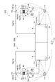
- FIG. 1 is a schematic diagram illustrating an embodiment of a carbon dioxide removal system.
- FIG. 2 is a schematic view showing another embodiment of the carbon dioxide removal system.
- a numerical range indicated by using “to” indicates a range including the numerical values described before and after “to” as the minimum value and the maximum value, respectively.
- the upper limit value or lower limit value of a numerical range of a certain step may be replaced with the upper limit value or lower limit value of the numerical range of another step.
- the upper limit value or the lower limit value of the numerical range may be replaced with the values shown in the examples.
- the term “process” is not limited to an independent process, and is included in this term if the intended purpose of the process is achieved even when it cannot be clearly distinguished from other processes. It is.
- the materials exemplified in the present specification can be used singly or in combination of two or more unless otherwise specified.
- the content of each component in the composition is the total amount of the plurality of substances present in the composition unless there is a specific notice when there are a plurality of substances corresponding to each component in the composition. Means.
- the adsorbent (carbon dioxide scavenger) according to the present embodiment contains cerium and a metal element having an electronegativity of 1.00 or more (excluding cerium, hereinafter referred to as “specific metal element” in some cases). Contains oxides.
- the adsorbent according to the present embodiment is used for removing (for example, recovering) carbon dioxide from a processing target gas (gas to be processed) containing carbon dioxide.
- the present inventors have used an adsorbent containing a cerium oxide containing cerium and a metal element having an electronegativity of 1.00 or more (excluding cerium), thereby increasing the temperature (for example, It has been found that the amount of carbon dioxide desorbed when heated to 100 to 200 ° C. can be improved.
- the peak temperature When the peak temperature can be lowered, the heating temperature for desorption of carbon dioxide can be lowered, and the removal efficiency of carbon dioxide can be improved.
- the peak temperature in a high temperature region for example, 100 to 200 ° C.
- a low temperature region for example, 50 ° C. or more and less than 100 ° C.
- the peak temperature in the high temperature region is preferably 150 ° C. or less, more preferably 140 ° C. or less, still more preferably 135 ° C. or less, and particularly preferably 130 ° C. or less, from the viewpoint of improving the carbon dioxide removal efficiency.
- 125 ° C. or lower is very preferable, and 120 ° C. or lower is very preferable.
- the peak temperature in the low temperature region is preferably 75 ° C. or less, more preferably 60 ° C. or less, still more preferably 55 ° C. or less, and 50 ° C. or less. Is particularly preferred.
- the electronegativity of the specific metal element is 1.00 or more from the viewpoint of improving the desorption amount of carbon dioxide when heated at a high temperature.
- As the value of electronegativity Pauling's electronegativity can be used.
- the electronegativity may be 1.05 or more, or 1.10 or more from the viewpoint of excellent balance between the desorption amount of carbon dioxide and the peak temperature of the desorption amount in a high temperature region. 1.12 or more, 1.15 or more, 1.20 or more, 1.25 or more, 1.30 or more 1.35 or more, 1.40 or more, 1.50 or more, 1.60 or more, 1.63 or more .
- the electronegativity of the specific metal element may be 1.90 or less, may be 1.85 or less, and may be 1.80 or less from the viewpoint of easily improving the amount of carbon dioxide desorption. It may be 1.70 or less, or 1.65 or less.
- the electronegativity of the specific metal element may be 1.00 to 1.80 from the viewpoint of excellent balance between the desorption amount of carbon dioxide and the peak temperature of the desorption amount in a high temperature region.
- the specific metal element is lanthanum (La), neodymium (Nd), yttrium (Y), magnesium (Mg) from the viewpoint of excellent balance between the desorption amount of carbon dioxide and the peak temperature of the desorption amount in a high temperature region. It is preferable to contain at least one selected from the group consisting of zirconium (Zr), aluminum (Al), zinc (Zn), iron (Fe), and copper (Cu).
- the specific metal element preferably contains at least one selected from the group consisting of neodymium, aluminum, and zinc from the viewpoint of excellent desorption amount in a low temperature region (for example, 50 ° C. or higher and lower than 100 ° C.).
- the said specific metal element contains neodymium from a viewpoint which is excellent in the balance of the desorption amount of a carbon dioxide, and the peak temperature of the desorption amount in a high temperature area
- the specific metal element preferably contains aluminum from the viewpoint of excellent balance between a high desorption amount of carbon dioxide and a peak temperature of the desorption amount in a high temperature region.
- the specific metal element preferably contains zinc from the viewpoint of excellent balance between the high desorption amount of carbon dioxide and the peak temperature of the desorption amount in the high temperature region.
- the specific surface area of the adsorbent according to the present embodiment from the viewpoint of elimination of carbon dioxide tends to easily increase, preferably greater than 130m 2 / g, more preferably at least 140m 2 / g, 150m 2 / g or more is more preferable, 160 m 2 / g or more is particularly preferable, and 170 m 2 / g or more is extremely preferable.
- the specific surface area of the adsorbent according to the present embodiment may be 250 m 2 / g or less, 240 m 2 / g or less, 230 m 2 / g or less, or 220 m 2 / g or less.
- the specific surface area (for example, BET specific surface area) can be measured according to the method described in Examples.
- the specific surface area can be adjusted by the kind of raw material for obtaining the adsorbent; the firing temperature and the oxygen concentration at the time of firing the raw material.
- the content of the cerium oxide in the adsorbent may be 30% by mass or more, 40% by mass or more, 45% by mass or more based on the total mass of the adsorbent, 50 It may be not less than mass%, may be not less than 70% by mass, and may be not less than 90% by mass.
- the adsorbent may be an embodiment made of cerium oxide (an embodiment in which the content of cerium oxide is substantially 100% by mass based on the total mass of the adsorbent). The greater the content of cerium oxide, the more the carbon dioxide adsorption and desorption can be further improved.
- the content of cerium oxide can be adjusted by, for example, the content of the cerium compound in the raw material for obtaining the adsorbent.
- Examples of the shape of the adsorbent include powder, pellets, granules, and honeycombs.
- the shape of the adsorbent may be determined in consideration of the required reaction rate, pressure loss, adsorption amount of the adsorbent, purity of the gas (adsorbed gas) adsorbed on the adsorbent (CO 2 purity), and the like.
- the adsorbent manufacturing method includes, for example, a firing step of firing a raw material containing a cerium compound containing the specific metal element.
- the cerium compound containing the specific metal element may be a complex salt.
- the cerium compound include cerium carbonate, cerium hydrogen carbonate, cerium oxalate, and cerium hydroxide.
- the raw material After the cerium nitrate (such as ammonium cerium nitrate) is reacted with the nitrate of the specific metal element to obtain a raw material containing a cerium compound, the raw material may be fired. In addition, after impregnating cerium oxide (CeO 2 ) with an aqueous solution of nitrate of the specific metal element to obtain a raw material containing a cerium compound, the raw material may be fired.
- cerium oxide CeO 2
- the cerium compound may be, for example, a compound containing cerium ions and at least one ion selected from the group consisting of carbonate ions and hydrogen carbonate ions.
- the cerium carbonate is a compound containing, for example, cerium ions and carbonate ions.
- Cerium hydrogen carbonate is a compound containing, for example, cerium ions and hydrogen carbonate ions.
- cerium carbonate examples include cerium carbonate and cerium oxycarbonate.
- cerium bicarbonate examples include cerium bicarbonate.
- the cerium compound may be at least one salt selected from the group consisting of cerium carbonate, cerium bicarbonate, and cerium oxycarbonate from the viewpoint of further improving the amount of adsorption and desorption of carbon dioxide.
- the content of the cerium compound may be 40% by mass or more, 45% by mass or more, 50% by mass or more, or 90% by mass or more based on the total mass of the raw material. 99 mass% or more may be sufficient.
- the raw material containing a cerium compound may be in an aspect made of a cerium compound (an aspect in which the content of the cerium compound is substantially 100% by mass based on the total mass of the raw material). The greater the content of the cerium compound, the more the carbon dioxide adsorption and desorption can be further improved.
- the firing temperature in the firing step is not particularly limited as long as it is a temperature at which the cerium compound can be decomposed.
- the firing temperature may be 150 ° C. or higher, 175 ° C. or higher, or 200 ° C. or higher from the viewpoint of shortening the production time of the adsorbent because decomposition of the cerium compound is likely to proceed. It may be 225 ° C or higher.
- the firing temperature may be 600 ° C. or lower, 500 ° C. or lower, or 400 ° C. or lower from the viewpoint that the specific surface area of the adsorbent tends to increase because sintering of cerium oxide hardly occurs. May be 350 degrees C or less, and 300 degrees C or less may be sufficient. From these viewpoints, the firing temperature may be 150 to 600 ° C., 175 to 500 ° C., 150 to 400 ° C., 200 to 400 ° C., 200 It may be -350 ° C or 225-300 ° C.
- the firing time in the firing step may be, for example, 10 minutes or longer.
- the firing time may be, for example, 10 hours or less, 3 hours or less, or 1 hour or less.
- the firing step may be performed in one step, or may be performed in multiple steps including two or more steps.
- at least one stage is the said baking temperature and / or baking time.
- the firing step can be performed, for example, in an air atmosphere, an oxygen atmosphere, or a reducing atmosphere.
- the dried raw material may be fired.
- the solution containing the raw material for example, a solution in which the cerium compound is dissolved
- the solution containing the raw material may be heated to remove the solvent and fire the raw material.
- the manufacturing method of the adsorbent according to the present embodiment may include a step of forming the raw material before firing into a predetermined shape (for example, the shape of the adsorbent described later), and the raw material after baking into a predetermined shape. You may provide the process to shape
- a predetermined shape for example, the shape of the adsorbent described later
- the carbon dioxide removal method according to the present embodiment includes an adsorption process in which the adsorbent according to the present embodiment is brought into contact with a processing target gas containing carbon dioxide to adsorb carbon dioxide to the adsorbent.
- the CO 2 concentration in the processing target gas may be 5000 ppm or less (0.5% by volume or less) based on the total volume of the processing target gas.
- carbon dioxide removal method carbon dioxide can be efficiently removed when the CO 2 concentration is 5000 ppm or less. The reason why such an effect is achieved is not clear, but the present inventors speculate that it is as follows. In the adsorption step, carbon dioxide is not physically adsorbed on the surface of the cerium oxide, but carbon dioxide is considered to be adsorbed to the adsorbent by chemically bonding with the surface of the cerium oxide.
- the carbon dioxide partial pressure dependency in the adsorption to the adsorbent is small, and even if the CO 2 concentration of the gas to be treated is 5000 ppm or less, the carbon dioxide is efficiently removed. It is assumed that carbon can be removed.
- CO 2 concentration from the viewpoint of even if the CO 2 concentration is low the effect of removing efficiently the carbon dioxide easily identified, based on the total volume of untreated gas may also be 2000ppm or less, 1500 ppm or less It may be 1000 ppm or less, or 800 ppm or less.
- the CO 2 concentration may be 100 ppm or more, 200 ppm or more, or 400 ppm or more on the basis of the total volume of the gas to be treated from the viewpoint of easily increasing the amount of carbon dioxide removed. From these viewpoints, the CO 2 concentration may be 100 to 5000 ppm, 100 to 2000 ppm, 100 to 1500 ppm, or 100 to 1000 ppm based on the total volume of the gas to be treated.
- the CO 2 concentration in the gas to be treated is not limited to the above range, and may be 500 to 5000 ppm or 750 to 5000 ppm.
- the gas to be treated is not particularly limited as long as it contains carbon dioxide, and may contain a gas component other than carbon dioxide.
- gas components other than carbon dioxide include water (water vapor, H 2 O), oxygen (O 2 ), nitrogen (N 2 ), carbon monoxide (CO), SOx, NOx, and volatile organic substances (VOC). It is done.
- Specific examples of the processing target gas include air in a room such as a building or a vehicle.
- these gas components may be adsorbed by the adsorbent.
- the CO 2 adsorptivity tends to be greatly reduced. Therefore, in order to improve the CO 2 adsorptivity of the adsorbent in the conventional method using the adsorbent, it is necessary to perform a dehumidification step of removing moisture from the target gas before bringing the target gas into contact with the adsorbent.
- the dehumidifying step is performed using, for example, a dehumidifying device, which leads to an increase in equipment and an increase in energy consumption.
- the adsorbent according to the present embodiment has excellent CO 2 adsorptivity compared to conventional adsorbents even when the gas to be treated contains water. Therefore, the carbon dioxide removal method according to the present embodiment does not require a dehumidification step, and carbon dioxide can be efficiently removed even when the gas to be treated contains water.
- the dew point of the gas to be treated may be 0 ° C. or higher.
- the relative humidity of the gas to be processed may be 30% or more, 50% or more, or 80% or more.
- the temperature T 1 of the adsorbent By adjusting the temperature T 1 of the adsorbent at the time of contact with the adsorbent untreated gas in the adsorption process, it is possible to adjust the amount of adsorption of carbon dioxide.
- the temperature T 1 may be ⁇ 20 to 100 ° C. or 10 to 40 ° C.
- Temperature T 1 of the adsorbent may be adjusted by heating or cooling the adsorbent may be used in combination of heating and cooling. Further, the temperature T 1 of the indirect adsorbent may be adjusted by heating or cooling the processed gas.
- a method of heating the adsorbent a method in which a heat medium (for example, heated gas or liquid) is brought into direct contact with the adsorbent; a heat medium (for example, heated gas or liquid) is circulated through a heat transfer tube, Examples include a method of heating the adsorbent by heat conduction from the heat transfer surface; a method of heating the adsorbent by an electric furnace that generates heat electrically, and the like.
- a method for cooling the adsorbent a method in which a refrigerant (for example, a cooled gas or liquid) is directly brought into contact with the adsorbent; a refrigerant (for example, a cooled gas or liquid) is circulated through a heat transfer tube or the like, and the heat transfer
- a refrigerant for example, a cooled gas or liquid
- the amount of carbon dioxide adsorbed can be adjusted by adjusting the total pressure of the atmosphere in which the adsorbent is present (for example, the total pressure in the container containing the adsorbent). As the total pressure is higher, the amount of CO 2 adsorbed by the adsorbent tends to increase.
- the total pressure is preferably 1 atm or more from the viewpoint of further improving the carbon dioxide removal efficiency.
- the total pressure may be 10 atm or less, 2 atm or less, or 1.3 atm or less from the viewpoint of energy saving.
- the total pressure may be 5 atmospheres or more.
- the total pressure of the atmosphere in which the adsorbent is present may be adjusted by pressurization or depressurization, and pressurization and depressurization may be used in combination.
- Examples of a method for adjusting the total pressure include a method in which the pressure is mechanically adjusted by a pump, a compressor, etc .; a method in which a gas having a pressure different from the pressure in the ambient atmosphere of the adsorbent is introduced.
- the adsorbent may be supported on a honeycomb-shaped base material or may be used by filling the adsorbent into a container.
- the use method of the adsorbent may be determined in consideration of the required reaction rate, pressure loss, the amount of adsorbent adsorbed, the purity of the gas (adsorbed gas) adsorbed on the adsorbent (CO 2 purity), and the like.
- the porosity is smaller. In this case, since the amount of gas other than carbon dioxide remaining in the gap is reduced, the purity of carbon dioxide in the adsorbed gas can be increased. On the other hand, when reducing the pressure loss, it is preferable that the porosity is large.
- the carbon dioxide removal method according to this embodiment may further include a desorption step of desorbing (desorbing) carbon dioxide from the adsorbent after the adsorption step.
- a method for desorbing carbon dioxide from the adsorbent As a method for desorbing carbon dioxide from the adsorbent, a method using the temperature dependence of the adsorption amount (temperature swing method; a method utilizing the difference in the adsorption amount of the adsorbent with temperature change); Examples include a method of using (pressure swing method, a method of using a difference in the amount of adsorbent adsorbed due to pressure change) and the like, and these methods may be used in combination (temperature / pressure swing method).
- the temperature of the adsorbent in the desorption process is set higher than that in the adsorption process.
- the method for heating the adsorbent include a method similar to the method for heating the adsorbent in the above-described adsorption step; From the viewpoint of reducing the energy required for heating, it is preferable to use the peripheral exhaust heat.
- the temperature difference (T 2 ⁇ T 1 ) between the adsorbent temperature T 1 in the adsorption step and the adsorbent temperature T 2 in the desorption step may be 200 ° C. or less, or 100 ° C. or less from the viewpoint of energy saving. It may be 50 degrees C or less.
- the temperature difference (T 2 ⁇ T 1 ) may be 10 ° C. or higher, 20 ° C. or higher, or 30 ° C. or higher from the viewpoint of easy desorption of carbon dioxide adsorbed on the adsorbent. Good.
- Temperature T 2 of the adsorbent in the desorption step for example, may be 40 ⁇ 300 ° C., may be 50 ⁇ 200 ° C., may be 80 ⁇ 120 ° C..
- the CO 2 adsorption amount increases as the total pressure of the atmosphere in which the adsorbent exists (for example, the total pressure in the container containing the adsorbent) increases. It is preferable to change so that the total pressure in the desorption process is lower than the total pressure.
- the total pressure may be adjusted by pressurizing or depressurizing, and pressurization and depressurization may be used in combination.
- a method for adjusting the total pressure for example, a method similar to the adsorption step described above can be used.
- the total pressure in the desorption process may be the ambient atmospheric pressure (for example, 1 atmosphere) or less than 1 atmosphere from the viewpoint of increasing the amount of CO 2 desorption.
- the carbon dioxide desorbed and recovered by the desorption process may be discharged to the outside as it is, but may be reused in the field using carbon dioxide.
- the CO 2 concentration May be reused to enhance.
- the CO 2 adsorptivity of the adsorbent in the adsorption process may be lowered. Therefore, it is preferable that the gas to be treated does not contain SOx, NOx, dust, or the like.
- the gas to be treated contains SOx, NOx, dust, or the like (for example, when the gas to be treated is exhaust gas discharged from a coal-fired power plant or the like), the carbon dioxide removal method according to this embodiment uses adsorption.
- an impurity removal step of removing impurities such as SOx, NOx, and dust from the gas to be treated before the adsorption step is preferable to further include an impurity removal step of removing impurities such as SOx, NOx, and dust from the gas to be treated before the adsorption step.
- the impurity removing step the impurities adsorbed on the adsorbent can be removed by heating the adsorbent.
- the impurity removal step can be performed using a removal device such as a denitration device, a desulfurization device, or a dust removal device, and the gas to be treated can be brought into contact with the adsorbent on the downstream side of these devices. .
- the adsorbent after the desorption process can be used again in the adsorption process.
- the adsorption step and the desorption step may be repeatedly performed after the desorption step.
- the adsorbent When the adsorbent is heated in the desorption step, the adsorbent may be cooled by the above-described method and used in the adsorption step.
- the adsorbent may be cooled by bringing a gas containing carbon dioxide (for example, a treatment target gas containing carbon dioxide) into contact with the adsorbent.
- the carbon dioxide removal method according to the present embodiment can be preferably carried out in a sealed space where the CO 2 concentration needs to be managed.
- the space in which the CO 2 concentration needs to be managed include a building, a vehicle, an automobile, a space station, a submersible, a food or chemical production plant, and the like.
- the carbon dioxide removal method according to this embodiment can be preferably carried out particularly in a space where the CO 2 concentration is limited to 5000 ppm or less (for example, a space where the density of people such as buildings and vehicles is high).
- the carbon dioxide removal method according to the present embodiment is preferably implemented in a food or chemical production plant or the like. Can do.
- the carbon dioxide removal system according to the present embodiment includes the carbon dioxide removal device according to the present embodiment.
- the carbon dioxide removal system according to the present embodiment includes the carbon dioxide removal device according to the present embodiment and a control unit for comprehensively controlling the carbon dioxide removal device.
- the carbon dioxide removal system (air conditioning system etc.) concerning this embodiment may be provided with two or more carbon dioxide removal devices (air conditioning equipment etc.) concerning this embodiment.
- the carbon dioxide removal system according to the present embodiment may include a control unit that comprehensively controls the operation of the plurality of carbon dioxide removal devices.
- the carbon dioxide removal device according to the present embodiment includes the adsorbent according to the present embodiment.
- the gas to be treated is introduced into the reaction vessel and the carbon dioxide is adsorbed by contacting the adsorbent disposed in the reaction vessel. Adsorb to.
- the carbon dioxide removal system and the carbon dioxide removal device according to the present embodiment may be used to reduce the carbon dioxide concentration in the air-conditioning target space, and to reduce the carbon dioxide concentration in the gas discharged from the plant or the like to the outside air. May be used.
- the air-conditioning target space may be, for example, a building; a vehicle; an automobile; a space station; a submersible; a food or chemical production plant.
- the carbon dioxide removing device may be an air conditioner.
- the air conditioner according to the present embodiment is an air conditioner used in an air conditioning target space including a processing target gas containing carbon dioxide.
- the air conditioner according to the present embodiment includes a flow path connected to the air conditioning target space, and a removal unit (carbon dioxide removal unit) that removes carbon dioxide contained in the processing target gas is disposed in the flow path.
- the adsorbent according to the present embodiment is disposed in the removal unit, and the adsorbent comes into contact with the processing target gas and carbon dioxide is adsorbed by the adsorbent.
- an air conditioning method including an adsorption process in which a processing target gas in an air conditioning target space is brought into contact with an adsorbent to adsorb carbon dioxide to the adsorbent.
- the details of the processing target gas containing carbon dioxide are the same as the processing target gas in the carbon dioxide removal method described above.
- the air conditioning system 200 includes an air conditioner 100 and a control device (control unit) 110.
- the air conditioner 100 includes a flow path 10, an exhaust fan (exhaust unit) 20, a concentration measuring device (concentration measuring unit) 30, an electric furnace (temperature control unit) 40, and a compressor (pressure control unit) 50. I have.
- the flow path 10 is connected to an air-conditioning target space R including a processing target gas (indoor gas) containing carbon dioxide.
- the flow path 10 includes a flow path section 10a, a flow path section 10b, a removal section (flow path section, carbon dioxide removal section) 10c, a flow path section 10d, a flow path section (circulation flow path) 10e,
- the removal part 10c is arrange
- the air conditioner 100 includes a removing unit 10c as a reaction container.
- a valve 70 a that adjusts the presence or absence of the inflow of the processing target gas in the removing unit 10 c and a valve 70 b that adjusts the flow direction of the processing target gas are arranged.
- the upstream end of the flow path part 10a is connected to the air conditioning target space R, and the downstream end of the flow path part 10a is connected to the upstream end of the flow path part 10b via the valve 70a.
- the upstream end of the removal part 10c is connected to the downstream end of the flow path part 10b.
- the downstream end of the removal part 10c is connected to the upstream end of the flow path part 10d.
- a downstream side of the flow path portion 10d in the flow path 10 is branched into a flow path section 10e and a flow path section 10f.
- the downstream end of the flow path portion 10d is connected to the upstream end of the flow path portion 10e and the upstream end of the flow path portion 10f via the valve 70b.
- the downstream end of the flow path part 10e is connected to the air conditioning target space R.
- the downstream end of the flow path portion 10f is connected to the outside air.
- the adsorbent 80 which is an adsorbent according to the present embodiment, is disposed in the removing unit 10c.
- the adsorbent 80 is filled in the central portion of the removal portion 10c. Two spaces are formed in the removal unit 10c via the adsorbent 80.
- the removal unit 10c includes an upstream space S1, a central portion S2 filled with the adsorbent 80, and a downstream space S3. And have.
- the space S1 is connected to the air conditioning target space R via the flow path portions 10a and 10b and the valve 70a, and the processing target gas containing carbon dioxide is supplied from the air conditioning target space R to the space S1 of the removal unit 10c. .
- the processing target gas supplied to the removing unit 10c moves from the space S1 to the space S3 via the central part S2, and is then discharged from the removing unit 10c.
- At least part of the carbon dioxide is removed from the processing target gas discharged from the air conditioning target space R in the removing unit 10c.
- the processing target gas from which carbon dioxide has been removed may be returned to the air conditioning target space R by adjusting the valve 70b or may be discharged to the outside air outside the air conditioning apparatus 100.
- the processing target gas discharged from the air conditioning target space R passes from upstream to downstream through the flow path part 10a, the flow path part 10b, the removal part 10c, the flow path part 10d, and the flow path part 10e. Can flow into R.
- processing target gas discharged from the air conditioning target space R is discharged from the upstream to the downstream via the flow path part 10a, the flow path part 10b, the removal part 10c, the flow path part 10d, and the flow path part 10f. May be.
- the exhaust fan 20 is disposed at the discharge position of the processing target gas in the air conditioning target space R.
- the exhaust fan 20 discharges the processing target gas from the air conditioning target space R and supplies it to the removing unit 10c.
- the concentration measuring device 30 measures the carbon dioxide concentration in the air conditioning target space R.
- the concentration measuring device 30 is disposed in the air conditioning target space R.
- the electric furnace 40 is disposed outside the removing unit 10c of the air conditioner 100, and can raise the temperature of the adsorbent 80.
- the compressor 50 is connected to the removing unit 10c of the air conditioner 100, and can adjust the pressure in the removing unit 10c.
- the control device 110 can perform overall operation control of the air conditioner 100. For example, based on the carbon dioxide concentration measured by the concentration measuring device 30, the presence or absence of inflow of the processing target gas in the removal unit 10c Can be controlled. Specifically, when the concentration measuring device 30 detects that the carbon dioxide concentration in the air-conditioning target space R has increased and reached a predetermined concentration due to exhalation or the like, concentration information is sent from the concentration measuring device 30 to the control device 110. Sent. The control device 110 that has received the concentration information opens the valve 70a and adjusts the gas discharged from the removal unit 10c so as to flow into the air-conditioning target space R through the flow channel unit 10d and the flow channel unit 10e.
- control apparatus 110 operates the exhaust fan 20, and supplies process target gas from the air-conditioning object space R to the removal part 10c. Furthermore, the control device 110 operates the electric furnace 40 and / or the compressor 50 as necessary to adjust the temperature of the adsorbent 80, the pressure in the removal unit 10c, and the like.
- the processing target gas supplied to the removing unit 10c moves from the space S1 to the space S3 via the central portion S2
- the processing target gas comes into contact with the adsorbent 80, and carbon dioxide in the processing target gas is absorbed into the adsorbent 80. Adsorb to.
- carbon dioxide is removed from the gas to be treated.
- the gas from which carbon dioxide has been removed is supplied to the air-conditioning target space R through the flow path part 10d and the flow path part 10e.
- the carbon dioxide adsorbed on the adsorbent 80 may be recovered in a state of being adsorbed on the adsorbent 80 without being desorbed from the adsorbent 80, or may be recovered after being desorbed from the adsorbent 80.
- the electric furnace 40 and / or the compressor 50 are operated to adjust the temperature of the adsorbent 80, the pressure in the removal unit 10c, etc.
- Carbon dioxide can be desorbed from 80.
- the valve 70b is adjusted so that the gas discharged from the removing unit 10c (the gas containing the desorbed carbon dioxide) is discharged to the outside air through the flow path unit 10f.
- the discharged carbon dioxide can be recovered.
- the air conditioning system 210 includes a first air conditioner 100 a, a second air conditioner 100 b, a control device (control unit) 110, and a control device (control unit) 120.
- the control device 120 controls the air conditioning operation of the first air conditioner 100a and the second air conditioner 100b by controlling the control device 110 described above in the first air conditioner 100a and the second air conditioner 100b. Control.
- the control device 120 may adjust the air conditioning operations of the first air conditioner 100a and the second air conditioner 100b to be performed under the same conditions, and the first air conditioner 100a and the second air conditioner 100b. You may adjust so that air-conditioning operation may be performed on different conditions.
- the control device 120 can transmit information regarding the presence or absence of the inflow of the processing target gas in the removal unit 10c to the control device 110.
- the carbon dioxide removal device and the carbon dioxide removal system are not limited to the above-described embodiment, and may be appropriately changed without departing from the gist thereof.
- the control content of the control unit of the carbon dioxide removal device is not limited to controlling the presence or absence of the inflow of the processing target gas in the reaction vessel, and the control unit may adjust the inflow amount of the processing target gas in the reaction vessel. Good.
- the gas to be processed may be supplied to the reaction vessel using a blower instead of the exhaust fan.
- the exhaust means may not be used.
- the temperature control means and the pressure control means are not limited to the electric furnace and the compressor, and various means described above can be used in the adsorption process and the desorption process.
- the temperature control means is not limited to the heating means, and may be a cooling means.
- each of the air-conditioning target space, the carbon dioxide removal unit, the exhaust unit, the temperature control unit, the pressure control unit, the concentration measurement unit, and the like is not limited to one, and a plurality of units may be arranged.
- the air conditioner includes a humidity controller for adjusting the dew point and relative humidity of the gas to be treated; a humidity measuring device for measuring the humidity of the air conditioning target space; a removal device such as a denitration device, a desulfurization device, and a dust removal device. May be.
- the adsorbent was pelletized with a press at 500 kgf. Next, after pulverizing the pellets, the pellets were sized using a sieve (particle size: 0.5 to 1.0 mm). Thereafter, 1.0 mL of the adsorbent was weighed and the adsorbent was fixed in the reaction tube. Subsequently, the adsorbent was dried at 120 ° C. in the atmosphere.
- a mixed gas containing 800 ppm of CO 2 , He (balance gas), and 2.3% by volume of water (H 2 O) is adjusted to 60 cm while adjusting the temperature of the adsorbent to 20 ° C. It was made to circulate through the reaction tube at a flow rate of 3 / min (total pressure in the reaction tube: 1 atm). Moisture was introduced by circulating gas through a bubbler. The CO 2 concentration of the outlet gas of the reaction tube was analyzed by gas chromatography, and the mixed gas was circulated until adsorption saturation was reached.
- the temperature of the adsorbent is increased from 20 ° C. at 2 ° C./min using an electric furnace while flowing the same mixed gas as in the adsorption step through the reaction tube at a flow rate of 60 cm 3 / min.
- the temperature was raised to 200 ° C. (total pressure in the reaction tube: 1 atm).
- total pressure in the reaction tube 1 atm.
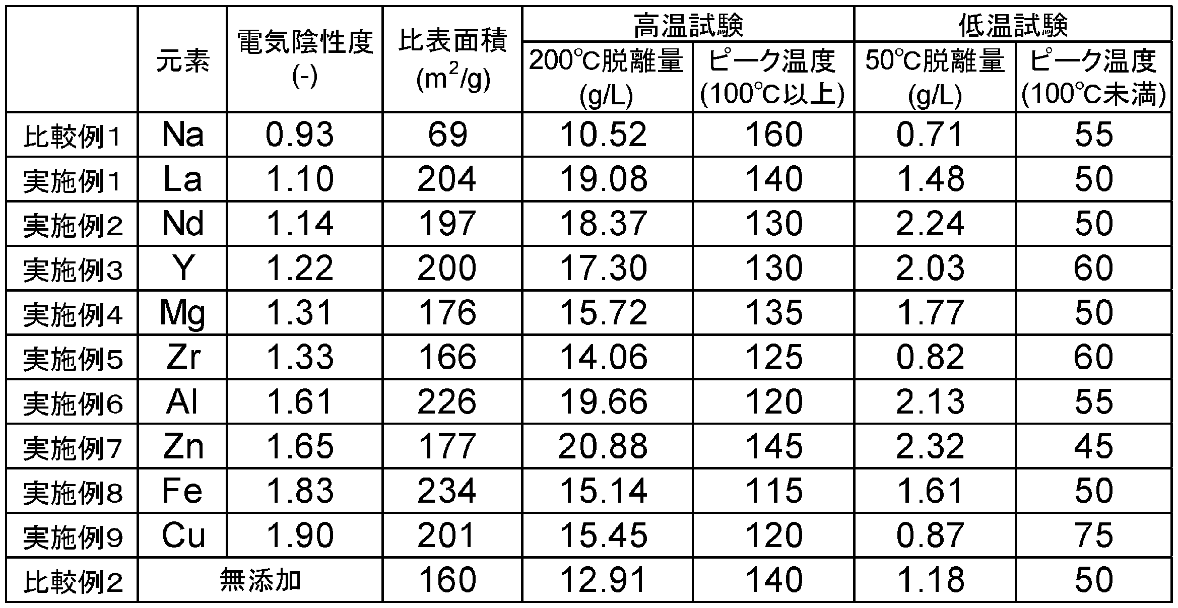
- CO 2 desorption amount was calculated by excluding CO 2 concentration in the mixed gas from the CO 2 concentration in the outlet gas (CO 2 concentration -800ppm outlet gas). The measurement results are shown in Table 1.
- the peak temperature of the peak appearing in the region of 50 ° C. or more and less than 100 ° C. and the peak temperature of the peak appearing in the region of 100 to 200 ° C. were calculated. .
- the measurement results are shown in Table 1.
- each example is superior in CO 2 desorption amount until reaching 200 ° C. as compared with the comparative example.
- cerium and another metal element are used together, it can be seen that in each example, the peak temperature in the high temperature region can be reduced as compared with Comparative Example 1.
Landscapes
- Chemical & Material Sciences (AREA)
- Analytical Chemistry (AREA)
- Chemical Kinetics & Catalysis (AREA)
- Organic Chemistry (AREA)
- Engineering & Computer Science (AREA)
- General Chemical & Material Sciences (AREA)
- Oil, Petroleum & Natural Gas (AREA)
- Inorganic Chemistry (AREA)
- Nanotechnology (AREA)
- Environmental & Geological Engineering (AREA)
- Thermal Sciences (AREA)
- Physics & Mathematics (AREA)
- Biomedical Technology (AREA)
- Health & Medical Sciences (AREA)
- Mechanical Engineering (AREA)
- Combustion & Propulsion (AREA)
- General Engineering & Computer Science (AREA)
- Geology (AREA)
- Life Sciences & Earth Sciences (AREA)
- Separation Of Gases By Adsorption (AREA)
- Solid-Sorbent Or Filter-Aiding Compositions (AREA)
- Treating Waste Gases (AREA)
- Inorganic Compounds Of Heavy Metals (AREA)
- Compounds Of Alkaline-Earth Elements, Aluminum Or Rare-Earth Metals (AREA)
- Compounds Of Iron (AREA)
Abstract
Description
CO2減少量=(室内のCO2濃度-外気のCO2濃度)×換気量
本実施形態に係る吸着剤(二酸化炭素捕捉剤)は、セリウムと、電気陰性度が1.00以上の金属元素(セリウムを除く。以下、場合により「特定金属元素」という)と、を含むセリウム酸化物を含有する。本実施形態に係る吸着剤は、二酸化炭素を含有する処理対象ガス(処理の対象となるガス)から二酸化炭素を除去(例えば回収)するために用いられる。
本実施形態に係る吸着剤の製造方法は、例えば、前記特定金属元素を含有するセリウム化合物を含む原料を焼成する焼成工程を備える。前記特定金属元素を含有するセリウム化合物は、複合塩であってもよい。セリウム化合物としては、セリウムの炭酸塩、セリウムの炭酸水素塩、セリウムのシュウ酸塩、セリウムの水酸化物等が挙げられる。このような吸着剤の製造方法では、セリウム化合物を含む原料を焼成することにより、当該セリウム化合物を分解し、且つ、セリウムを酸化する。セリウムの硝酸塩(硝酸アンモニウムセリウム等)と前記特定金属元素の硝酸塩とを反応させて、セリウム化合物を含む原料を得た後に、当該原料を焼成してもよい。また、前記特定金属元素の硝酸塩の水溶液を酸化セリウム(CeO2)に含浸させて、セリウム化合物を含む原料を得た後に、当該原料を焼成してもよい。
本実施形態に係る二酸化炭素の除去方法は、本実施形態に係る吸着剤を、二酸化炭素を含有する処理対象ガスに接触させて二酸化炭素を当該吸着剤に吸着させる吸着工程を備える。
本実施形態に係る二酸化炭素除去システムは、本実施形態に係る二酸化炭素除去装置を備える。例えば、本実施形態に係る二酸化炭素除去システムは、本実施形態に係る二酸化炭素除去装置と、当該二酸化炭素除去装置を統括的に制御するための制御手段と、を備える。本実施形態に係る二酸化炭素除去システム(空調システム等)は、本実施形態に係る二酸化炭素除去装置(空調装置等)を複数備えていてもよい。本実施形態に係る二酸化炭素除去システムは、複数の二酸化炭素除去装置の運転を統括的に制御する制御部を備えていてもよい。本実施形態に係る二酸化炭素除去装置は、本実施形態に係る吸着剤を備えている。
(比較例1)
精製水2.0gに炭酸ナトリウム0.32gを溶解させて得た溶液を市販の酸化セリウム(CeO2)粉末5.16gに添加した。そして、空気中120℃で乾燥させた後、空気中300℃で1時間焼成することによって吸着剤(Ce:Na=5:1(モル比))を得た。
ビーカーに純水300mLと尿素60.0gとを加え、均一になるまで撹拌した。次に、硝酸二アンモニウムセリウム(IV)16.45gを加え、30℃で10分間撹拌した。その後、硝酸ランタン(III)・6水和物2.60gを加え、30℃で10分間撹拌した。その後、撹拌を継続したまま30分かけて95℃まで昇温し、95℃で3時間温度を保持し、これにより沈殿が生じた。沈殿が生じた際のpHは5~6であった。溶液を室温(25℃)まで冷却した後、吸引ろ過によって固体を分離した後に水洗した。そして、120℃で1時間乾燥した後、300℃で1時間焼成することによって吸着剤(Ce:La=5:1(モル比))を得た。
硝酸ランタン(III)・6水和物2.60gを硝酸ネオジム・6水和物2.63gへ変更したこと以外は実施例1と同様にして吸着剤(Ce:Nd=5:1(モル比))を得た。
硝酸ランタン(III)・6水和物2.60gを硝酸イットリウム・6水和物2.30gへ変更したこと以外は実施例1と同様にして吸着剤(Ce:Y=5:1(モル比))を得た。
硝酸ランタン(III)・6水和物2.60gを硝酸マグネシウム・6水和物1.54gへ変更したこと以外は実施例1と同様にして吸着剤(Ce:Mg=5:1(モル比))を得た。
硝酸ランタン(III)・6水和物2.60gを硝酸ジルコニル・2水和物1.60gへ変更したこと以外は実施例1と同様にして吸着剤(Ce:Zr=5:1(モル比))を得た。
硝酸ランタン(III)・6水和物2.60gを硝酸アルミニウム・9水和物2.25gへ変更したこと以外は実施例1と同様にして吸着剤(Ce:Al=5:1(モル比))を得た。
硝酸ランタン(III)・6水和物2.60gを硝酸亜鉛・6水和物1.78gへ変更したこと以外は実施例1と同様にして吸着剤(Ce:Zn=5:1(モル比))を得た。
硝酸ランタン(III)・6水和物2.60gを硝酸鉄(III)・9水和物2.42gへ変更したこと以外は実施例1と同様にして吸着剤(Ce:Fe=5:1(モル比))を得た。
硝酸ランタン(III)・6水和物2.60gを硝酸銅(II)・3水和物1.45gへ変更したこと以外は実施例1と同様にして吸着剤(Ce:Cu=5:1(モル比))を得た。
硝酸ランタン(III)・6水和物を用いなかったこと以外は実施例1と同様にして吸着剤を得た。
各吸着剤のBET比表面積を測定した。まず、前処理として、真空引きを行いながら200℃で吸着剤を加熱した。次いで、-196℃での窒素の吸着等温線を測定した。続いて、BET(Brunauer-Emmett-Teller)法を用いてBET比表面積を測定した。測定結果を表1に示す。
実施例及び比較例の吸着剤を用いて、昇温脱離測定(TPD:Temperature Programmed Desorption Measurement)により各温度におけるCO2脱離量を以下の手順で測定した。
Claims (13)
- 二酸化炭素を含有する処理対象ガスから二酸化炭素を除去するために用いられる吸着剤であって、
セリウムと、電気陰性度が1.00以上の金属元素(セリウムを除く)と、を含むセリウム酸化物を含有する、吸着剤。 - 前記金属元素の前記電気陰性度が1.00~1.80である、請求項1に記載の吸着剤。
- 前記金属元素が、ランタン、ネオジム、イットリウム、マグネシウム、ジルコニウム、アルミニウム、亜鉛、鉄及び銅からなる群より選ばれる少なくとも1種を含む、請求項1に記載の吸着剤。
- 前記金属元素がネオジムを含む、請求項1に記載の吸着剤。
- 前記金属元素がアルミニウムを含む、請求項1に記載の吸着剤。
- 前記金属元素が亜鉛を含む、請求項1に記載の吸着剤。
- 比表面積が130m2/gを超える、請求項1~6のいずれか一項に記載の吸着剤。
- 前記セリウム酸化物の含有量が、吸着剤の全質量基準で90質量%以上である、請求項1~7のいずれか一項に記載の吸着剤。
- 請求項1~8のいずれか一項に記載の吸着剤を、二酸化炭素を含有する処理対象ガスに接触させて二酸化炭素を前記吸着剤に吸着させる工程を備える、二酸化炭素の除去方法。
- 前記処理対象ガスの二酸化炭素濃度が5000ppm以下である、請求項9に記載の二酸化炭素の除去方法。
- 前記処理対象ガスの二酸化炭素濃度が1000ppm以下である、請求項9に記載の二酸化炭素の除去方法。
- 請求項1~8のいずれか一項に記載の吸着剤を備える、二酸化炭素除去装置。
- 請求項12に記載の二酸化炭素除去装置を備える、二酸化炭素除去システム。
Priority Applications (5)
| Application Number | Priority Date | Filing Date | Title |
|---|---|---|---|
| CA3024077A CA3024077A1 (en) | 2016-05-16 | 2017-03-31 | Adsorbent, method for removing carbon dioxide, device for removing carbon dioxide, and system for removing carbon dioxide |
| US16/301,745 US20190255509A1 (en) | 2016-05-16 | 2017-03-31 | Adsorbent, method for removing carbon dioxide, device for removing carbon dioxide, and system for removing carbon dioxide |
| CN201780029889.8A CN109153002A (zh) | 2016-05-16 | 2017-03-31 | 吸附剂、二氧化碳的除去方法、二氧化碳除去装置、以及二氧化碳除去系统 |
| JP2018518141A JPWO2017199599A1 (ja) | 2016-05-16 | 2017-03-31 | 吸着剤、二酸化炭素の除去方法、二酸化炭素除去装置、及び、二酸化炭素除去システム |
| EP17799033.0A EP3459625A4 (en) | 2016-05-16 | 2017-03-31 | ABSORPTION AGENT, CARBON DIOXIDE REMOVAL METHOD, CARBON DIOXIDE REMOVAL DEVICE, AND CARBON DIOXIDE REMOVAL SYSTEM |
Applications Claiming Priority (8)
| Application Number | Priority Date | Filing Date | Title |
|---|---|---|---|
| JP2016098203 | 2016-05-16 | ||
| JP2016-098203 | 2016-05-16 | ||
| JP2016098200 | 2016-05-16 | ||
| JP2016-098200 | 2016-05-16 | ||
| JP2016-129064 | 2016-06-29 | ||
| JP2016129064 | 2016-06-29 | ||
| JP2016-167643 | 2016-08-30 | ||
| JP2016167643 | 2016-08-30 |
Publications (1)
| Publication Number | Publication Date |
|---|---|
| WO2017199599A1 true WO2017199599A1 (ja) | 2017-11-23 |
Family
ID=60325823
Family Applications (3)
| Application Number | Title | Priority Date | Filing Date |
|---|---|---|---|
| PCT/JP2017/013638 Ceased WO2017199598A1 (ja) | 2016-05-16 | 2017-03-31 | 吸着剤、二酸化炭素の除去方法、二酸化炭素除去装置、及び、二酸化炭素除去システム |
| PCT/JP2017/013677 Ceased WO2017199599A1 (ja) | 2016-05-16 | 2017-03-31 | 吸着剤、二酸化炭素の除去方法、二酸化炭素除去装置、及び、二酸化炭素除去システム |
| PCT/JP2017/018198 Ceased WO2017199908A1 (ja) | 2016-05-16 | 2017-05-15 | 吸着剤、二酸化炭素の除去方法、二酸化炭素除去器、及び空調装置 |
Family Applications Before (1)
| Application Number | Title | Priority Date | Filing Date |
|---|---|---|---|
| PCT/JP2017/013638 Ceased WO2017199598A1 (ja) | 2016-05-16 | 2017-03-31 | 吸着剤、二酸化炭素の除去方法、二酸化炭素除去装置、及び、二酸化炭素除去システム |
Family Applications After (1)
| Application Number | Title | Priority Date | Filing Date |
|---|---|---|---|
| PCT/JP2017/018198 Ceased WO2017199908A1 (ja) | 2016-05-16 | 2017-05-15 | 吸着剤、二酸化炭素の除去方法、二酸化炭素除去器、及び空調装置 |
Country Status (7)
| Country | Link |
|---|---|
| US (3) | US20190255509A1 (ja) |
| EP (3) | EP3459624A4 (ja) |
| JP (3) | JPWO2017199599A1 (ja) |
| CN (3) | CN109153000A (ja) |
| CA (3) | CA3024077A1 (ja) |
| TW (1) | TW201806667A (ja) |
| WO (3) | WO2017199598A1 (ja) |
Cited By (1)
| Publication number | Priority date | Publication date | Assignee | Title |
|---|---|---|---|---|
| JP2024072324A (ja) * | 2022-11-16 | 2024-05-28 | 株式会社フクハラ | Co2分離方法及び植物育成方法 |
Families Citing this family (4)
| Publication number | Priority date | Publication date | Assignee | Title |
|---|---|---|---|---|
| KR102248613B1 (ko) * | 2019-07-29 | 2021-05-07 | 한국과학기술연구원 | 아민계 이산화탄소 흡착제용 금속산화물 촉매, 이를 포함하는 아민계 이산화탄소 흡착제 및 흡탈착 장치 |
| JP7092717B2 (ja) * | 2019-08-08 | 2022-06-28 | フタバ産業株式会社 | 二酸化炭素施用装置 |
| CN110452743B (zh) * | 2019-09-04 | 2020-06-05 | 西安凯尔文石化助剂制造有限公司 | 一种高效脱硫剂 |
| JP7790915B2 (ja) * | 2021-10-21 | 2025-12-23 | 清水建設株式会社 | 二酸化炭素分離回収装置、二酸化炭素分離回収システム及び二酸化炭素分離回収方法 |
Citations (7)
| Publication number | Priority date | Publication date | Assignee | Title |
|---|---|---|---|---|
| JP2000140549A (ja) | 1998-11-09 | 2000-05-23 | Tosoh Corp | 二酸化炭酸の除去方法 |
| JP2012024648A (ja) * | 2010-07-20 | 2012-02-09 | Hitachi Ltd | 二酸化炭素捕捉材 |
| JP2012110874A (ja) * | 2010-11-29 | 2012-06-14 | Hitachi Ltd | 二酸化炭素捕捉材 |
| JP2013059703A (ja) * | 2011-09-12 | 2013-04-04 | Hitachi Ltd | 二酸化炭素捕捉材 |
| JP2013158770A (ja) * | 2012-02-02 | 2013-08-19 | Samsung Electronics Co Ltd | 二酸化炭素吸着剤、その製造方法およびこれを含む二酸化炭素捕集モジュール |
| JP2015150500A (ja) * | 2014-02-14 | 2015-08-24 | 日立化成株式会社 | 二酸化炭素捕捉材及びこれを用いた二酸化炭素回収装置 |
| WO2015125355A1 (ja) * | 2014-02-21 | 2015-08-27 | シャープ株式会社 | 二酸化炭素濃度制御装置および電子機器 |
Family Cites Families (11)
| Publication number | Priority date | Publication date | Assignee | Title |
|---|---|---|---|---|
| FR2559754A1 (fr) * | 1984-02-20 | 1985-08-23 | Rhone Poulenc Spec Chim | Oxyde cerique a nouvelles caracteristiques morphologiques et son procede d'obtention |
| FR2596381B1 (fr) * | 1986-03-26 | 1988-05-27 | Rhone Poulenc Chimie | Oxydes ceriques a nouvelles caracteristiques morphologiques et leur procede d'obtention |
| FR2608583B1 (fr) * | 1986-12-19 | 1990-12-07 | Rhone Poulenc Chimie | Oxyde cerique a nouvelles caracteristiques morphologiques et son procede d'obtention |
| US5279789A (en) * | 1988-12-23 | 1994-01-18 | Rhone-Poulenc Chimie | Ceric oxide particulates having improved morphology |
| JPH0975714A (ja) * | 1995-09-07 | 1997-03-25 | Matsushita Electric Ind Co Ltd | 二酸化炭素ガス吸着剤及び二酸化炭素ガス交換器 |
| AU2009316229A1 (en) * | 2008-11-11 | 2010-05-20 | The University Of Queensland | A method for producing sorbents for CO2 capture under high temperatures |
| JP2011173059A (ja) * | 2010-02-24 | 2011-09-08 | Hitachi Ltd | 二酸化炭素吸着材及びこれを用いた二酸化炭素回収装置 |
| CN103831077B (zh) * | 2012-11-23 | 2016-09-14 | 黄炳照 | 陶瓷材料、二氧化碳的吸附方法及二氧化碳的转化方法 |
| CN103521162A (zh) * | 2013-10-11 | 2014-01-22 | 南京理工大学 | 铈改性的钙基双功能颗粒、制备方法及其应用 |
| CN104566693A (zh) * | 2014-12-29 | 2015-04-29 | 浙江信立实业有限公司 | 一种中央空调空气净化系统及方法 |
| CN104785195A (zh) * | 2015-04-03 | 2015-07-22 | 天津大学 | 掺杂惰性组分的氧化钙基高温二氧化碳吸附剂材料及制备方法 |
-
2017
- 2017-03-31 EP EP17799032.2A patent/EP3459624A4/en not_active Withdrawn
- 2017-03-31 CA CA3024077A patent/CA3024077A1/en not_active Abandoned
- 2017-03-31 US US16/301,745 patent/US20190255509A1/en not_active Abandoned
- 2017-03-31 CN CN201780029707.7A patent/CN109153000A/zh active Pending
- 2017-03-31 WO PCT/JP2017/013638 patent/WO2017199598A1/ja not_active Ceased
- 2017-03-31 JP JP2018518141A patent/JPWO2017199599A1/ja not_active Withdrawn
- 2017-03-31 US US16/301,758 patent/US20190151821A1/en not_active Abandoned
- 2017-03-31 JP JP2018518140A patent/JPWO2017199598A1/ja not_active Withdrawn
- 2017-03-31 CA CA3024074A patent/CA3024074A1/en not_active Abandoned
- 2017-03-31 EP EP17799033.0A patent/EP3459625A4/en not_active Withdrawn
- 2017-03-31 CN CN201780029889.8A patent/CN109153002A/zh active Pending
- 2017-03-31 WO PCT/JP2017/013677 patent/WO2017199599A1/ja not_active Ceased
- 2017-05-15 JP JP2018518283A patent/JPWO2017199908A1/ja active Pending
- 2017-05-15 CA CA3024086A patent/CA3024086A1/en not_active Abandoned
- 2017-05-15 CN CN201780029741.4A patent/CN109153001A/zh active Pending
- 2017-05-15 EP EP17799332.6A patent/EP3459626A4/en not_active Withdrawn
- 2017-05-15 WO PCT/JP2017/018198 patent/WO2017199908A1/ja not_active Ceased
- 2017-05-15 US US16/301,744 patent/US20190217241A1/en not_active Abandoned
- 2017-05-16 TW TW106116048A patent/TW201806667A/zh unknown
Patent Citations (7)
| Publication number | Priority date | Publication date | Assignee | Title |
|---|---|---|---|---|
| JP2000140549A (ja) | 1998-11-09 | 2000-05-23 | Tosoh Corp | 二酸化炭酸の除去方法 |
| JP2012024648A (ja) * | 2010-07-20 | 2012-02-09 | Hitachi Ltd | 二酸化炭素捕捉材 |
| JP2012110874A (ja) * | 2010-11-29 | 2012-06-14 | Hitachi Ltd | 二酸化炭素捕捉材 |
| JP2013059703A (ja) * | 2011-09-12 | 2013-04-04 | Hitachi Ltd | 二酸化炭素捕捉材 |
| JP2013158770A (ja) * | 2012-02-02 | 2013-08-19 | Samsung Electronics Co Ltd | 二酸化炭素吸着剤、その製造方法およびこれを含む二酸化炭素捕集モジュール |
| JP2015150500A (ja) * | 2014-02-14 | 2015-08-24 | 日立化成株式会社 | 二酸化炭素捕捉材及びこれを用いた二酸化炭素回収装置 |
| WO2015125355A1 (ja) * | 2014-02-21 | 2015-08-27 | シャープ株式会社 | 二酸化炭素濃度制御装置および電子機器 |
Non-Patent Citations (1)
| Title |
|---|
| See also references of EP3459625A4 |
Cited By (2)
| Publication number | Priority date | Publication date | Assignee | Title |
|---|---|---|---|---|
| JP2024072324A (ja) * | 2022-11-16 | 2024-05-28 | 株式会社フクハラ | Co2分離方法及び植物育成方法 |
| JP7511272B2 (ja) | 2022-11-16 | 2024-07-05 | 株式会社フクハラ | Co2分離方法及び植物育成方法 |
Also Published As
| Publication number | Publication date |
|---|---|
| JPWO2017199908A1 (ja) | 2019-03-14 |
| WO2017199908A1 (ja) | 2017-11-23 |
| TW201806667A (zh) | 2018-03-01 |
| CA3024086A1 (en) | 2017-11-23 |
| CN109153002A (zh) | 2019-01-04 |
| US20190151821A1 (en) | 2019-05-23 |
| EP3459624A4 (en) | 2020-01-15 |
| CN109153001A (zh) | 2019-01-04 |
| US20190255509A1 (en) | 2019-08-22 |
| CA3024074A1 (en) | 2017-11-23 |
| EP3459625A1 (en) | 2019-03-27 |
| CA3024077A1 (en) | 2017-11-23 |
| JPWO2017199598A1 (ja) | 2019-03-14 |
| CN109153000A (zh) | 2019-01-04 |
| EP3459625A4 (en) | 2020-01-22 |
| WO2017199598A1 (ja) | 2017-11-23 |
| EP3459624A1 (en) | 2019-03-27 |
| US20190217241A1 (en) | 2019-07-18 |
| EP3459626A4 (en) | 2020-01-22 |
| EP3459626A1 (en) | 2019-03-27 |
| JPWO2017199599A1 (ja) | 2019-03-14 |
Similar Documents
| Publication | Publication Date | Title |
|---|---|---|
| WO2017199599A1 (ja) | 吸着剤、二酸化炭素の除去方法、二酸化炭素除去装置、及び、二酸化炭素除去システム | |
| JPWO2017199920A1 (ja) | 空調装置、空調システム、二酸化炭素の除去方法、吸着剤及び二酸化炭素除去器 | |
| WO2018003323A1 (ja) | 吸着剤及びその製造方法、二酸化炭素の除去方法、二酸化炭素除去器、並びに、空調装置 | |
| JP2018065069A (ja) | 吸着剤及びその製造方法、二酸化炭素の除去方法、並びに、空調装置 | |
| JPWO2017199917A1 (ja) | 吸着剤及びその製造方法、二酸化炭素の除去方法、二酸化炭素除去器、並びに、空調装置 | |
| JPWO2017199919A1 (ja) | 吸着剤、二酸化炭素の除去方法、二酸化炭素除去器、及び、空調装置 | |
| JP2018001074A (ja) | 吸着剤及びその製造方法、二酸化炭素の除去方法、並びに、空調装置 | |
| JP2018034088A (ja) | 吸着剤、二酸化炭素の除去方法、及び、空調装置 | |
| JP2018038940A (ja) | 吸着剤、二酸化炭素の除去方法、及び、空調装置 | |
| JP2018065068A (ja) | 吸着剤及びその製造方法、二酸化炭素の除去方法、並びに、空調装置 | |
| JP2018051505A (ja) | 吸着体の製造方法、及び、二酸化炭素の除去方法 | |
| JP2019094229A (ja) | 液状組成物及びその製造方法 | |
| JP2018051504A (ja) | 吸着剤、当該吸着剤を備える吸着体、これらの製造方法、及び、二酸化炭素の除去方法 | |
| JP2021023879A (ja) | 吸着剤及びその製造方法、並びに二酸化炭素の除去方法 |
Legal Events
| Date | Code | Title | Description |
|---|---|---|---|
| WWE | Wipo information: entry into national phase |
Ref document number: 2018518141 Country of ref document: JP |
|
| ENP | Entry into the national phase |
Ref document number: 3024077 Country of ref document: CA |
|
| NENP | Non-entry into the national phase |
Ref country code: DE |
|
| 121 | Ep: the epo has been informed by wipo that ep was designated in this application |
Ref document number: 17799033 Country of ref document: EP Kind code of ref document: A1 |
|
| ENP | Entry into the national phase |
Ref document number: 2017799033 Country of ref document: EP Effective date: 20181217 |