WO2017199614A1 - Système optique d'objectif - Google Patents
Système optique d'objectif Download PDFInfo
- Publication number
- WO2017199614A1 WO2017199614A1 PCT/JP2017/014122 JP2017014122W WO2017199614A1 WO 2017199614 A1 WO2017199614 A1 WO 2017199614A1 JP 2017014122 W JP2017014122 W JP 2017014122W WO 2017199614 A1 WO2017199614 A1 WO 2017199614A1
- Authority
- WO
- WIPO (PCT)
- Prior art keywords
- lens
- lens group
- optical system
- objective optical
- image
- Prior art date
- Legal status (The legal status is an assumption and is not a legal conclusion. Google has not performed a legal analysis and makes no representation as to the accuracy of the status listed.)
- Ceased
Links
- 0 C1CC*CC1 Chemical compound C1CC*CC1 0.000 description 4
- JSMRMEYFZHIPJV-UHFFFAOYSA-N C1C2CCC1C2 Chemical compound C1C2CCC1C2 JSMRMEYFZHIPJV-UHFFFAOYSA-N 0.000 description 1
- PTFFTFXAXAVZPZ-UHFFFAOYSA-N C1C2[O]=CC1C2 Chemical compound C1C2[O]=CC1C2 PTFFTFXAXAVZPZ-UHFFFAOYSA-N 0.000 description 1
- ZTQCWRZJWGMGCH-UHFFFAOYSA-N CCCC1CC(CC)CC1 Chemical compound CCCC1CC(CC)CC1 ZTQCWRZJWGMGCH-UHFFFAOYSA-N 0.000 description 1
Images




Classifications
-
- A—HUMAN NECESSITIES
- A61—MEDICAL OR VETERINARY SCIENCE; HYGIENE
- A61B—DIAGNOSIS; SURGERY; IDENTIFICATION
- A61B1/00—Instruments for performing medical examinations of the interior of cavities or tubes of the body by visual or photographical inspection, e.g. endoscopes; Illuminating arrangements therefor
- A61B1/00064—Constructional details of the endoscope body
- A61B1/00071—Insertion part of the endoscope body
- A61B1/0008—Insertion part of the endoscope body characterised by distal tip features
- A61B1/00096—Optical elements
-
- A—HUMAN NECESSITIES
- A61—MEDICAL OR VETERINARY SCIENCE; HYGIENE
- A61B—DIAGNOSIS; SURGERY; IDENTIFICATION
- A61B1/00—Instruments for performing medical examinations of the interior of cavities or tubes of the body by visual or photographical inspection, e.g. endoscopes; Illuminating arrangements therefor
- A61B1/00163—Optical arrangements
- A61B1/00188—Optical arrangements with focusing or zooming features
-
- G—PHYSICS
- G02—OPTICS
- G02B—OPTICAL ELEMENTS, SYSTEMS OR APPARATUS
- G02B13/00—Optical objectives specially designed for the purposes specified below
- G02B13/04—Reversed telephoto objectives
-
- G—PHYSICS
- G02—OPTICS
- G02B—OPTICAL ELEMENTS, SYSTEMS OR APPARATUS
- G02B23/00—Telescopes, e.g. binoculars; Periscopes; Instruments for viewing the inside of hollow bodies; Viewfinders; Optical aiming or sighting devices
- G02B23/24—Instruments or systems for viewing the inside of hollow bodies, e.g. fibrescopes
- G02B23/2407—Optical details
- G02B23/2423—Optical details of the distal end
- G02B23/243—Objectives for endoscopes
- G02B23/2438—Zoom objectives
-
- G—PHYSICS
- G02—OPTICS
- G02B—OPTICAL ELEMENTS, SYSTEMS OR APPARATUS
- G02B23/00—Telescopes, e.g. binoculars; Periscopes; Instruments for viewing the inside of hollow bodies; Viewfinders; Optical aiming or sighting devices
- G02B23/24—Instruments or systems for viewing the inside of hollow bodies, e.g. fibrescopes
- G02B23/26—Instruments or systems for viewing the inside of hollow bodies, e.g. fibrescopes using light guides
Definitions
- the present invention relates to an objective optical system having a focusing function, and more particularly, to an objective optical system such as an endoscope objective optical system capable of magnifying observation and other consumer-use small cameras.
- General objective lenses for endoscopes have a wide depth of field.
- the depth of field is, for example, 5 mm to 100 mm.
- an object image is picked up by an image pickup device, thereby providing an image of the object.
- an image pickup device for example, a CCD (Charge Coupled Devices) or a C-MOS (Complementary Metal Oxide Semiconductor) is used as the imaging device.
- the number of pixels can be increased by reducing the pixel area. However, if the number of pixels is significantly increased, the size of the image sensor increases even if the area of the pixels is reduced. When the size of the image sensor increases, it is necessary to increase the focal length of the objective lens.
- the depth of field of the objective lens is reduced. As described above, when an image quality higher than the conventional image quality is obtained, the depth of field of the objective lens is narrowed.
- the depth of field is the range on the object side where a clear object image can be obtained.
- the range in which a clear object image can be obtained becomes narrow.
- the objective lens may have a focusing function. For this reason, there is an increasing need for an objective lens having a focusing function.
- magnifying endoscope objective lens an objective lens having a magnifying function
- the magnifying endoscope objective lens needs to be able to observe a wider range than the observation range in the magnifying observation.
- the distance from the objective lens to the object position (hereinafter referred to as “object distance”) is, for example, about 1 mm to 3 mm.
- object distance is, for example, about 1 mm to 3 mm.
- normal observation the observation in a wide range as described above (hereinafter referred to as “normal observation”), the object distance is much longer than 3 mm.
- normal image is a focused image
- magnified image an object image in magnified observation
- the objective lens may have a focusing function. Since the objective lens has a focusing function, both a normal image and an enlarged image can be observed in a focused state. For this reason, the need for an objective lens having a focusing function is increasing.
- Patent Documents 1 to 8 disclose an objective lens composed of three lens groups.
- the objective lenses disclosed in Patent Documents 1 to 5 include, in order from the object side, a lens group having a positive refractive power, a lens group having a negative refractive power, and a lens group having a positive refractive power. .
- the objective lens disclosed in Patent Document 6 includes, in order from the object side, a lens group having a negative refractive power, a lens group having a positive refractive power, and a lens group having a negative refractive power.
- the objective lenses disclosed in Patent Documents 7 and 8 have, in order from the object side, a lens group having a negative refractive power, a lens group having a positive refractive power, and a lens group having a positive refractive power. .
- Patent Document 8 discloses an objective lens different from the above-described objective lens.
- Another objective lens includes a lens group having a positive refractive power, a lens group having a positive refractive power, and a lens group having a negative refractive power.
- Still another objective lens includes a lens group having a negative refractive power, a lens group having a negative refractive power, and a lens group having a positive refractive power.
- Japanese Examined Patent Publication No. 61-042883 Japanese Patent Laid-Open No. 06-317744 JP-A-11-316339 JP 2009-29496 A JP 2012-32576 A JP 2000-267002 A Japanese Patent No. 3765500 Japanese Patent Publication No. 4-3851
- magnifying endoscope an image sensor having a large number of pixels is used. Further, downsizing is progressing year by year in an imaging element having a large number of pixels. For this reason, the magnifying endoscope objective lens also needs to cope with the downsizing of the image sensor.
- ⁇ S imply reducing the size of a conventional objective lens increases the sensitivity to manufacturing errors. If the sensitivity to the manufacturing error is high, the amount of aberration changes greatly even if the amount of error is small. As described above, when the conventional objective lens is simply reduced in size, the influence on the imaging performance is increased.
- Patent Documents 1 to 8 are objective lenses having a sufficiently small F number. Therefore, it cannot be said that these objective lenses have imaging performance corresponding to a small and high-definition image sensor.
- the objective lens is an objective lens corresponding to a high-definition image sensor.
- the image position is adjusted during assembly.
- a normal image is formed at the image position of the objective lens.
- the imaging surface of the imaging element is located at the image position of the objective lens. Therefore, in the adjustment of the image position, for example, adjustment for moving the entire objective lens or adjustment for moving a part of the objective lens is performed so that the normal image is formed on the imaging surface.
- adjustment sensitivity the ratio of the amount of image movement to the amount of lens adjustment during image position adjustment
- the adjustment sensitivity can be lowered by arranging a lens on the imaging element side, for example, immediately before the imaging surface.
- a lens is disposed on the image sensor side. This lens is a field lens, and is disposed mainly so that the principal ray incident on the imaging surface is substantially parallel to the optical axis. Since the refractive power of this lens is not so large, it is difficult to sufficiently reduce the adjustment sensitivity.
- the present invention has been made in view of such problems, and an object thereof is to provide an objective optical system that is not easily affected by various errors and in which various aberrations are well corrected.
- an objective optical system includes: In order from the object side, a first lens group having a positive refractive power, a second lens group having a negative refractive power, and a third lens group having a positive refractive power, Focus by moving the second lens group,
- the third lens group includes at least a positive lens and a cemented lens,
- the cemented lens of the third lens group has a positive lens and a negative lens,
- the first sub lens group of the third lens group is located closer to the object side than the predetermined air interval
- the second sub lens group of the third lens group is located on the image side with respect to a predetermined air interval
- the predetermined air interval is the maximum air interval among the air intervals in the third lens group, The following conditional expressions (1) and (2) are satisfied.
- fp is the combined focal length from the first lens group to the first sub lens group
- f is the focal length of the entire objective optical system when focusing on a long distance object point
- tt is a predetermined air interval
- the objective optical system according to an embodiment of the present invention is less susceptible to various errors, and can provide an objective optical system in which various aberrations are favorably corrected.
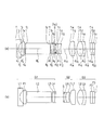
- FIG. 1 is a cross-sectional view of an objective optical system according to Example 1.
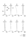
- FIG. FIG. 4 is an aberration diagram of the objective optical system according to Example 1.
- 6 is a cross-sectional view of an objective optical system according to Example 2.
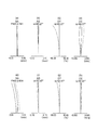
- FIG. 6 is an aberration diagram of the objective optical system according to Example 2.
- 6 is a cross-sectional view of an objective optical system according to Example 3.
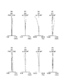
- FIG. 6 is an aberration diagram of the objective optical system according to Example 3.
- 6 is a cross-sectional view of an objective optical system according to Example 4.
- FIG. 6 is an aberration diagram of the objective optical system according to Example 4.
- 10 is a cross-sectional view of an objective optical system in Example 5.
- FIG. 10 is an aberration diagram of the objective optical system according to Example 5.
- the objective optical system according to this embodiment can be used for an objective lens of an endoscope, for example.
- the objective optical system according to the present embodiment can perform normal observation and magnified observation with one optical system in endoscopic observation.
- the objective optical system is composed of a plurality of lens groups, and at least one lens group of the plurality of lens groups moves on the optical axis.
- the objective optical system includes, in order from the object side, a first lens group having a positive refractive power, a second lens group having a negative refractive power, and a third lens group having a positive refractive power. Focusing is performed by moving the lens group, and the third lens group includes at least a positive lens and a cemented lens, and the cemented lens of the third lens group includes a positive lens and a negative lens.
- the first sub lens group of the third lens group is located closer to the object side than the predetermined air interval, and the second sub lens group of the third lens group is located closer to the image side than the predetermined air interval.
- the predetermined air interval is the maximum air interval among the air intervals in the third lens group.
- the objective optical system includes, in order from the object side, a first lens group having a positive refractive power, a second lens group having a negative refractive power, and a third lens group having a positive refractive power.
- the object distance is different between normal observation and magnified observation.
- the object point distance changes continuously between the normal observation and the magnified observation.
- the lens group to be moved for focusing may be any lens group.
- the number of lens groups to be moved may be one or more.
- the number of lens groups to be moved is small. If the number of lens groups to be moved is one, the driving mechanism can be simplified.
- the number of lens groups to be moved is small. For example, when the entire objective optical system is moved, all lens groups are moved. In this case, the weight of the lens group to be moved increases. This increases the burden on the drive mechanism and increases the size of the drive mechanism. Therefore, it is not preferable to move all the lens groups.
- the lens group can be fixed, and the image sensor can be moved instead.
- a drive mechanism is also required when moving the image sensor.
- the structure of the drive mechanism is complicated. Therefore, the weight of the drive mechanism is increased.
- the burden on the drive mechanism increases, and the drive mechanism also increases in size. Therefore, it is not preferable to move the image sensor.
- focusing is performed by moving the second lens group. Since the number of lens groups to be moved is one, the focusing mechanism can be simplified.
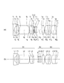
- FIG. 1A and 1B are cross-sectional views illustrating a specific configuration of the objective optical system according to the present embodiment, in which FIG. 1A is a cross-sectional view of Configuration Example 1 and FIG.
- the objective optical system includes, in order from the object side, a first lens group G1 having a positive refractive power, a second lens group G2 having a negative refractive power, and a third lens group G3 having a positive refractive power.
- An aperture stop S is disposed between the first lens group G1 and the second lens group G2.
- the first lens group G1 includes, in order from the object side, a negative first lens L1, a positive second lens L2, a positive third lens L3, and a negative fourth lens L4.
- the third lens L3 and the fourth lens L4 are cemented to form a cemented lens CL1.
- the second lens group G2 includes, in order from the object side, a negative fifth lens L5 and a positive sixth lens L6.
- the fifth lens L5 and the sixth lens L6 are cemented to form a cemented lens CL2. Since the refractive power of the second lens group G2 is negative, the refractive power of the cemented lens CL2 is negative.
- FIG. 1A shows a state in which a long-distance object point is focused. In focusing on a short-distance object point, the second lens group G2 moves to the image side.
- the third lens group G3 includes, in order from the object side, a positive seventh lens L7, a positive eighth lens L8, and a negative ninth lens L9.
- the eighth lens L8 and the ninth lens L9 are cemented to form a cemented lens CL3.
- the third lens group G3 has a first sub lens group SUB1 and a second sub lens group SUB2.
- the first sub lens group SUB1 is located closer to the object side than the predetermined air interval.
- the second sub lens group SUB2 is located on the image side with respect to a predetermined air interval.
- the predetermined air interval is the maximum air interval among the air intervals in the third lens group G3.
- the predetermined air interval is an air interval between adjacent lenses.
- the number of air intervals between adjacent lenses is one.
- This air space is the air space between the seventh lens L7 and the eighth lens L8. Therefore, the air interval between the seventh lens L7 and the eighth lens L8 is a predetermined air interval.
- the first sub lens group SUB1 is configured by a seventh lens L7
- the second sub lens group SUB2 is configured by an eighth lens L8 and a ninth lens L9.
- a first parallel plate F1 is disposed between the first lens L1 and the second lens L2.
- the first parallel flat plate F1 can be arranged at an arbitrary position in the objective optical system.
- a second parallel plate F2 and a third parallel plate F3 are disposed on the image side of the ninth lens L9. The second parallel plate F2 and the third parallel plate F3 are joined.
- the second parallel plate F2 and the third parallel plate F3 are cover glasses for the image sensor.
- An image sensor (not shown) is disposed on the image side of the third parallel plate F3.
- the image side surface of the third parallel plate F3 is an image surface I.
- the imaging surface of the imaging element coincides with the image side surface of the third parallel plate F3.
- the objective optical system includes, in order from the object side, a first lens group G1 having a positive refractive power, a second lens group G2 having a negative refractive power, and a third lens group G3 having a positive refractive power.
- An aperture stop S is disposed between the first lens group G1 and the second lens group G2.
- the first lens group G1 includes, in order from the object side, a negative first lens L1, a positive second lens L2, a positive third lens L3, and a negative fourth lens L4.
- the third lens L3 and the fourth lens L4 are cemented to form a cemented lens CL1.
- the second lens group G2 includes, in order from the object side, a negative fifth lens L5 and a positive sixth lens L6.
- the fifth lens L5 and the sixth lens L6 are cemented to form a cemented lens CL2. Since the refractive power of the second lens group G2 is negative, the refractive power of the cemented lens CL2 is negative.
- FIG. 1B shows a state in which a long distance object point is focused. In focusing on a short-distance object point, the second lens group G2 moves to the image side.
- the third lens group G3 includes, in order from the object side, a positive seventh lens L7, a positive eighth lens L8, a negative ninth lens L9, and a positive tenth lens L10.
- the eighth lens L8 and the ninth lens L9 are cemented to form a cemented lens CL3.
- the third lens group G3 has a first sub lens group SUB1 and a second sub lens group SUB2.
- the first sub lens group SUB1 is located closer to the object side than the predetermined air interval.
- the second sub lens group SUB2 is located on the image side with respect to a predetermined air interval.
- the number of air intervals between adjacent lenses is two.
- the first air interval is an air interval between the seventh lens L7 and the eighth lens L8.
- the second air interval is an air interval between the ninth lens L9 and the tenth lens L10.
- the second air interval is larger than the first air interval. Therefore, the air interval between the ninth lens L9 and the tenth lens L10 is a predetermined air interval.
- the first sub lens group SUB1 includes a seventh lens L7, an eighth lens L8, and a ninth lens L9, and the second sub lens group SUB2 includes a tenth lens L10.
- a first parallel plate F1 is disposed between the first lens L1 and the second lens L2.
- the first parallel flat plate F1 can be arranged at an arbitrary position in the objective optical system.
- a second parallel flat plate F2 is disposed on the image side of the tenth lens L10.
- the second parallel flat plate F2 is cemented with the tenth lens L10.
- the second parallel flat plate F2 is a cover glass of the image sensor.
- An image sensor (not shown) is disposed on the image side of the second parallel plate F2.
- the image side surface of the second parallel flat plate F2 is an image surface I.
- the imaging element is arranged so that the imaging surface coincides with the image side surface of the second parallel plate F2.
- the image side surface of the tenth lens L10 may be the image surface I.
- the tenth lens L10 can be directly attached to the imaging surface.
- the imaging unit is configured with an objective optical system and an imaging device, the imaging unit can be shortened by doing in this way.
- the second sub lens group SUB2 is joined to the second parallel flat plate F2. Therefore, the image side surface of the second sub lens group SUB2 is limited to a flat surface.
- the second sub-lens group SUB2 and the second parallel flat plate F2 are arranged with an air gap therebetween.
- the image side surface of the second sub lens group SUB2 can have a shape other than a plane. Therefore, in the configuration example 1, the magnitude of the refractive power of the second sub lens group SUB2 can be freely set. As a result, in the configuration example 1, the aberration correction capability can be improved as compared to the configuration example 2. As described above, Configuration Example 1 is advantageous for improving the image quality.
- the total length of the optical system is longer than that in the configuration example 2.
- the aperture stop S is disposed on the object side of the second lens group G2.
- the aperture stop S By arranging the aperture stop S in the vicinity of the second lens group G2, the height of the light beam passing through the second lens group G2 can be reduced. As a result, the outer diameter of the second lens group G2 can be reduced.
- the second lens group G2 moves at the time of focusing. By moving the second lens group G2, it is possible to focus wherever an object point is located from a long distance to a short distance. Normal observation can be performed when focusing on a long-distance object point, and magnified observation can be performed when focusing on a short-distance object point.
- the second lens group G2 In order to move the second lens group G2 in the optical axis direction, a moving mechanism is required. As described above, in the basic configuration, the second lens group G2 can be reduced in size, so that the moving mechanism can be easily disposed around the second lens group G2.
- the weight of the moving lens groups can be reduced. Therefore, the load applied to the moving mechanism can be reduced. Furthermore, the moving mechanism can be simplified.
- a moving mechanism for example, there is an actuator.
- the actuator is connected to a lens frame that holds the second lens group G2, and thereby a driving force is applied to the lens frame.
- the third lens group G3 includes at least a positive lens and a cemented lens. Thereby, spherical aberration and chromatic aberration can be corrected satisfactorily. There may be a plurality of positive lenses and cemented lenses.
- the first plane-parallel plate F1 is disposed in the first lens group G1.
- the first plane-parallel plate F1 cuts light of a specific wavelength, for example, YAG laser light (wavelength 1060 nm), semiconductor laser light (wavelength 810 nm), or near-infrared wavelength light. It is a filter for.
- the objective optical system according to the present embodiment has the above basic configuration and satisfies the following conditional expression (1). 1.21 ⁇ fp / f ⁇ 2.42 (1) here, fp is the combined focal length from the first lens group to the first sub lens group, f is the focal length of the entire objective optical system when focusing on a long distance object point, It is.
- the objective optical system is an objective optical system corresponding to a high-definition and small-sized image sensor. In such an objective optical system, the minimum circle of confusion is very small and the adjustment sensitivity is increased. Therefore, when adjusting the image position, if the entire objective optical system is moved along the optical axis, it is difficult to adjust the image position.
- adjustment group a part of the objective optical system lens
- fixed group the remaining lenses
- the adjustment sensitivity By reducing the adjustment sensitivity, the movement amount of the adjustment group (hereinafter referred to as “adjustment amount”) can be increased to some extent. Therefore, the lens can be accurately moved without complicating the mechanism for moving the lens. That is, the image position can be adjusted with high accuracy. If the adjustment sensitivity is low, the influence of various aberrations on the occurrence of errors in the adjusted objective optical system is small, and an objective optical system that maintains high imaging performance can be realized.
- the adjustment group is constituted by a lens located on the object side of the fixed group. For this reason, in the objective optical system according to the present embodiment, the first lens group to the first sub lens group are used as the adjustment group.
- Conditional expression (1) is a conditional expression for making the objective optical system the most suitable optical system for adjusting the image position.
- conditional expression (1) the meaning of dividing the refractive power of the entire objective optical system into an adjustment group and a fixed group is almost lost. Therefore, it is not preferable to fall below the lower limit value of conditional expression (1).
- conditional expression (1) If the upper limit of conditional expression (1) is exceeded, the refractive power of the adjustment group becomes too small. In this case, the adjustment sensitivity can be lowered, but the focal length of the fixed group becomes relatively short. When the focal length of the fixed group becomes shorter, the amount of spherical aberration generated in the fixed group increases. For this reason, it is difficult to realize an objective optical system corresponding to a high-definition image sensor.
- conditional expression (1 ′) It is preferable to satisfy the following conditional expression (1 ′) instead of conditional expression (1). 1.3 ⁇ fp / f ⁇ 2.2 (1 ′)
- Satisfying conditional expression (1 ') further increases the above-described effect. Therefore, it is possible to reduce the adjustment sensitivity.
- satisfying the conditional expressions (1) and (1 ′) it is possible to adjust the image position with high accuracy in any configuration of the optical system. Therefore, an objective optical system having high imaging performance can be realized.
- the objective optical system according to the present embodiment preferably satisfies the following conditional expression (2). 0.35 ⁇ tt / f ⁇ 0.6 (2) here, tt is a predetermined air interval, f is the focal length of the entire objective optical system when focusing on a long distance object point, It is.
- the adjustment group is moved along the optical axis.
- the adjustment amount of the adjustment group is determined at a predetermined interval. Therefore, the conditional expression (2) represents a conditional expression regarding this adjustment amount.
- conditional expression (2) If the lower limit value of conditional expression (2) is not reached, it is difficult to ensure a sufficient predetermined interval. In this case, a sufficient adjustment amount cannot be secured. Therefore, if the manufacturing error becomes large, the image position cannot be adjusted.
- conditional expression (2) If the upper limit of conditional expression (2) is exceeded, the amount of adjustment can be secured sufficiently. However, since the adjustment amount becomes large, the entire length of the optical system becomes long. In addition, the size of the frame member that holds the lens is increased. Therefore, it is not preferable to exceed the upper limit value of conditional expression (2).
- the predetermined air interval can be regarded as a range in which the adjustment group can move.
- the movable range is wider than the range (adjustment amount) necessary for adjustment. If the upper limit value of conditional expression (2) is exceeded, the predetermined interval becomes larger than necessary, so that the total length of the optical system is further increased.
- the objective optical system according to the present embodiment preferably satisfies the following conditional expression (3). -15 ⁇ fG2 / f ⁇ -5 (3) here, fG2 is the focal length of the second lens group, f is the focal length of the entire objective optical system when focusing on a long distance object point, It is.
- the objective optical system of the present embodiment has a focusing function.
- the second lens group is moved according to a change in the object distance.
- the relationship between the object distance and the position in the optical axis direction of the second lens group at the time of focusing is determined at the time of design. Therefore, when focusing is performed, the second lens group may be moved according to the object distance, and the second lens group may be stopped at the design position.
- the stationary position of the second lens group coincides with the designed position.
- an error occurs between the stationary position of the second lens group and the design position.
- error sensitivity at the time of focusing the ratio of the amount of focus deviation to the amount of error
- the conditional expression (3) When the conditional expression (3) is satisfied, the error sensitivity at the time of focusing can be lowered, and aberration fluctuations at the time of focusing can also be suppressed.
- conditional expression (3) If the lower limit of conditional expression (3) is not reached, the variation in field curvature accompanying the movement of the second lens group becomes large. In this case, a significant difference appears between the image plane position during normal observation and the image plane position during close-up observation. Therefore, it is not preferable to fall below the lower limit value of conditional expression (3).
- conditional expression (3) If the upper limit of conditional expression (3) is exceeded, the refractive power of the second lens group will increase. In this case, the error sensitivity during focusing increases.
- the second lens group may be decentered, for example, tilted or shifted.
- the error sensitivity at the time of focusing is high, even if the amount of decentration of the lens group is small, the imaging performance is significantly deteriorated. For this reason, it is not preferable to exceed the upper limit value of conditional expression (3).
- the objective optical system according to this embodiment can perform normal observation and magnified observation. Therefore, the focusing range on the object side is wide. In such an objective optical system, it is necessary to further suppress fluctuations in the image plane position when switching from normal observation to magnified observation.
- conditional expression (3) -11 ⁇ fG2 / f ⁇ -5 (3 ')
- Satisfying conditional expression (3 ') can further reduce fluctuations in the image plane position during focusing.
- the objective optical system according to the present embodiment preferably satisfies the following conditional expression (4). 0.7 ⁇ fG3SUB1 / fG3SUB2 ⁇ 1.4 (4) here, fG3SUB1 is the focal length of the first sub lens unit, fG3SUB2 is the focal length of the second sub lens group, It is.
- the second sub lens group In the adjustment of the image position, the second sub lens group is fixed with respect to the image position. Then, the first lens group is moved to the first sub lens group. Therefore, in the adjustment of the image position, the interval between the first sub lens group and the second sub lens group changes. If the variation in aberration is large when the interval is changed, the imaging performance is deteriorated when the image position is adjusted. Aberration fluctuations, particularly field curvature fluctuations, that occur during image position adjustment can be minimized by making the refractive power of the first sub lens group and the refractive power of the second sub lens group appropriate.
- Conditional expression (4) is a conditional expression of the ratio between the refractive power of the first sub lens group and the refractive power of the second sub lens group.
- conditional expression (4) If the lower limit of conditional expression (4) is not reached, the field curvature will be excessive. On the other hand, if the upper limit of conditional expression (4) is exceeded, the curvature of field becomes too under. In either case, the amount of curvature of field is large, so that the variation in field curvature increases when adjusting the image position.
- the objective optical system according to the present embodiment preferably satisfies the following conditional expression (5). -6 ⁇ fG2 / fG1 ⁇ -2 (5) here, fG2 is the focal length of the second lens group, fG1 is the focal length of the first lens group, It is.
- Conditional expression (5) is a conditional expression for setting the refractive power of the second lens group to an appropriate refractive power.
- the refractive power of the second lens group can be set to an appropriate magnitude. As a result, fluctuations in the image plane position during focusing can be suppressed, and the optical system can be downsized.
- conditional expression (5) If the upper limit value of conditional expression (5) is exceeded, the variation in field curvature accompanying focusing will increase. In this case, there is a significant difference between the image position during normal observation and the image position during magnified observation. Therefore, it is not preferable to exceed the upper limit value of conditional expression (5).
- the objective optical system according to the present embodiment preferably satisfies the following conditional expression (6). -7.6 ⁇ fG2 / fG3 ⁇ -2.4 (6) here, fG2 is the focal length of the second lens group, fG3 is the focal length of the third lens group, It is.
- Conditional expression (6) is a conditional expression related to correction of field curvature. When the conditional expression (6) is satisfied, the curvature of field can be favorably corrected.
- conditional expression (6) If the lower limit of conditional expression (6) is not reached, the field curvature will be excessive. If the upper limit value of conditional expression (6) is exceeded, the curvature of field becomes too under. In either case, since the image plane is inclined, it is impossible to focus at either the central portion or the peripheral portion of the image.
- the objective optical system according to the present embodiment preferably satisfies the following conditional expression (7).
- fG3 is the focal length of the third lens group
- fG1 is the focal length of the first lens group, It is.
- Conditional expression (7) is a conditional expression regarding correction of lateral chromatic aberration. By satisfying conditional expression (7), the lateral chromatic aberration can be satisfactorily corrected.
- conditional expression (7) If the lower limit value of conditional expression (7) is not reached, the difference between the chromatic aberration of magnification at the C line and the chromatic aberration of magnification at the F line becomes overcorrected. In addition, with axial chromatic aberration, the balance of the amount of aberration at each wavelength is lost. Therefore, it is not preferable to fall below the lower limit value of conditional expression (7).
- conditional expression (7) If the upper limit of conditional expression (7) is exceeded, lateral chromatic aberration will be undercorrected. Therefore, it is not preferable because it exceeds the upper limit value of conditional expression (7).
- conditional expression (7) If the conditional expression (7) is not satisfied, color blur occurs at the periphery of the image. For this reason, the contrast is lowered at the periphery of the image.
- the objective optical system according to the present embodiment preferably satisfies the following conditional expression (8). 1.4 ⁇ (t12 + t23) / f ⁇ 3.2 (8) here, t12 is the distance between the first lens group and the second lens group when focusing on a long-distance object point, t23 is an interval between the second lens unit and the third lens unit at the time of focusing on a long-distance object point, f is the focal length of the entire objective optical system when focusing on a long distance object point, It is.
- Conditional expression (8) is a conditional expression related to the amount of movement of the lens group during focusing.
- conditional expression (8) When the lower limit value of conditional expression (8) is not reached, the distance between the first lens group and the third lens group becomes shorter. Therefore, it is difficult to secure a space necessary for moving the second lens group.
- the object distance is around 2 mm.
- the second lens group must be moved in a narrow space.
- the refractive power of the second lens group must be increased.
- the stationary position of the second lens group at the time of focusing is determined at the time of design.
- the refractive power of the second lens group is large, an image in focus at the image position is not formed even if the difference between the stationary position of the second lens group and the designed position is small.
- conditional expression (8) If the upper limit value of conditional expression (8) is exceeded, the distance between the first lens group and the third lens group becomes too large. In this case, a space necessary for moving the second lens group can be secured, but the optical system becomes large.
- conditional expression 8 ′ 1.8 ⁇ (t12 + t23) / f ⁇ 2.9 (8 ')
- conditional expression (8 ') it is possible to secure the minimum space necessary for the movement of the second lens group and sufficiently reduce the size of the optical system.
- the first lens group includes the first lens and satisfies the following conditional expression (9). -0.8 ⁇ fL1 / fG1 ⁇ -0.5 (9) here, fL1 is the focal length of the first lens, fG1 is the focal length of the first lens group, It is.
- Conditional expression (9) is a conditional expression related to reduction of error sensitivity related to the angle of view.
- An error in the air interval between the first lens and the second lens (hereinafter referred to as “interval L12”) greatly contributes to fluctuations in the angle of view as compared to errors in other lens intervals.
- the second lens group moves at the time of focusing. If an error occurs in the stationary position of the second lens group, the angle of view changes greatly during use even if the angle of view can be adjusted at the time of manufacture. Thus, when an error occurs after adjustment, the change in the angle of view due to the error also increases. Therefore, it is not preferable to exceed the upper limit value of conditional expression (9).
- the objective optical system according to the present embodiment preferably satisfies the following conditional expression (10). 1.8 ⁇ rG3SUB2F / f ⁇ 5.2 (10) here, rG3SUB2F is the radius of curvature of the lens surface located closest to the object side in the second sub lens group, f is the focal length of the entire objective optical system when focusing on a long distance object point, It is.
- Conditional expression (10) is a conditional expression for making the angle of the principal ray incident on the image plane (hereinafter referred to as “incident angle”) appropriate. This angle is an angle formed by the principal ray and the optical axis. When an image is picked up by the image pickup device, the image pickup surface of the image pickup device serves as an image plane. Therefore, here, the angle of the principal ray incident on the imaging surface is also referred to as the incident angle.
- the amount of light detected by the pixel decreases as the incident angle increases. Even if the incident angle is the same, the smaller the pixel area, the smaller the amount of light detected.
- a small and high-definition image sensor has a small pixel area. Therefore, in a small and high-definition image sensor, it is necessary to make the incident angle small to some extent.
- the objective optical system is a telecentric optical system.
- the incident angle is small. Therefore, a bright image can be acquired even using a small and high-definition image sensor.
- the diameter of the lens is increased.
- the amount of spherical aberration generated at the entrance surface of the lens disposed closest to the image plane increases.
- conditional expression (10) When the upper limit of conditional expression (10) is exceeded, the incident angle increases. In this case, the amount of light detected is smaller in the pixels located around the imaging surface. As a result, peripheral darkening occurs in the captured image.
- conditional expression (1) cannot be satisfied. Therefore, the effect of lowering the adjustment sensitivity is reduced.
- conditional expression (10 ′) It is preferable to satisfy the following conditional expression (10 ′) instead of conditional expression (10). 2.3 ⁇ rG3SUB2F / f ⁇ 4.9 (10 ′)
- conditional expression (10 ') it is possible to further reduce the size of the optical system and lower the adjustment sensitivity.
- the third lens group includes a positive lens and a cemented lens in order from the object side.
- the cemented lens is positioned on the image side. Therefore, it is possible to reduce the occurrence of longitudinal chromatic aberration and lateral chromatic aberration.
- the first sub lens group is a positive lens
- the second sub lens group is a cemented lens
- the third lens group further includes another cemented lens, and the other cemented lens includes a positive lens and a negative lens.
- the third lens group includes a positive lens, a cemented lens, and another cemented lens in order from the object side.
- the two cemented lenses are positioned closest to the image side. Therefore, it is possible to further reduce the occurrence of axial chromatic aberration and lateral chromatic aberration.
- the first sub lens group is composed of a positive lens
- the second sub lens group is composed of a cemented lens and another cemented lens.
- the first sub lens group is composed of a positive lens and a cemented lens
- the second sub lens group is composed of another cemented lens
- the third lens group further includes another positive lens.
- the third lens group includes a positive lens, another positive lens, and a cemented lens in order from the object side.
- the cemented lens is positioned closest to the image side. Therefore, it is possible to reduce the occurrence of longitudinal chromatic aberration and lateral chromatic aberration.
- the first sub lens group SUB1 is composed of a positive lens
- the second sub lens group SUB2 is composed of a positive lens and a cemented lens.
- the third lens group includes a positive lens, a cemented lens, and another positive lens in order from the object side.
- the cemented lens is positioned on the image side. Therefore, it is possible to reduce the occurrence of longitudinal chromatic aberration and lateral chromatic aberration.
- the first sub lens group includes a positive lens and a cemented lens
- the second sub lens group includes a cemented lens
- the objective optical system according to the present embodiment preferably satisfies the following conditional expression (11). 4.0 ⁇ fG3SUB2F / f ⁇ 6.5 (11) here, fG3SUB2F is the focal length of a given lens surface, f is the focal length of the entire objective optical system when focusing on a long distance object point, The predetermined lens surface is a lens surface located closest to the object side of the second sub lens group, It is.
- Conditional expression (11) is a conditional expression related to reduction of adjustment sensitivity.
- conditional expression (11) If the lower limit of conditional expression (11) is not reached, error sensitivity related to peripheral performance increases. In addition, the influence on the deflection angle becomes large. Therefore, it is not preferable to fall below the lower limit of conditional expression (11).
- the adjustment sensitivity can be reduced.
- the radius of curvature of the lens surface becomes small.
- the error sensitivity related to the peripheral performance is increased.
- the influence on the deflection angle becomes significant.
- conditional expression (11) If the upper limit of conditional expression (11) is exceeded, the refractive power of the second sub lens group of the optical system becomes small, so that the refractive power of the moving group becomes relatively large. In this case, the adjustment sensitivity is increased. This makes it difficult to adjust the image position.
- conditional expression (11 ′) or (11 ′′) is satisfied instead of conditional expression (11).
- conditional expression (11) 4.5 ⁇ f3GF / f ⁇ 6.5 (11 ')
- conditional expression (11) 4.5 ⁇ f3GF / f ⁇ 5.5 (11 ")
- Satisfying conditional expressions (11 ′) and (11 ′′) can further reduce the adjustment sensitivity. As a result, the manufacturing cost can be reduced.
- the lens located closest to the image side of the third lens group is preferably a plano-convex lens
- the object side surface of the plano-convex lens is preferably a convex surface on the object side.
- the light incident on the image plane can be refracted so as to approach the optical axis.
- the image side surface of the plano-convex lens is flat, it can be bonded to the imaging surface or the cover glass of the imaging element can be attached.
- the objective optical system according to the present embodiment preferably has a predetermined cemented lens, and the predetermined cemented lens is preferably arranged on the object side of the aperture stop so as to be adjacent to the aperture stop.
- the predetermined cemented lens is composed of a biconvex lens and a negative meniscus lens having a convex surface facing the image side, which is disposed closest to the image side in the first lens group. preferable.
- the objective optical system according to the present embodiment preferably satisfies the following conditional expression (12).
- fGlCL is the focal length of a given cemented lens
- rG1CL is the radius of curvature of the cemented surface of a given cemented lens
- Conditional expression (12) is a conditional expression related to correction of axial chromatic aberration.
- conditional expression (12) When the lower limit of conditional expression (12) is not reached, axial chromatic aberration is overcorrected, and in addition, spherical aberration becomes under and chromatic aberration of magnification also increases. Therefore, it is not preferable to fall below the lower limit value of conditional expression (12).
- conditional expression (12) If the upper limit of conditional expression (12) is exceeded, axial chromatic aberration will be undercorrected. As a result, the contrast of the image is reduced. Therefore, it is not preferable to exceed the upper limit value of conditional expression (12).
- the first lens group includes, in order from the object side, a plano-concave lens having a concave surface facing the image side, a positive meniscus lens having a convex surface facing the image side, a biconvex lens, and the image side. It is preferable to have at least a negative meniscus lens having a convex surface facing the surface.
- a biconvex lens and a negative meniscus lens having a convex surface facing the image side are cemented.
- the shape of the positive lens constituting the cemented lens is a biconvex shape, spherical aberration can be corrected well.
- the first lens group includes, in order from the object side, a plano-concave lens having a concave surface facing the image side, a positive meniscus lens having a convex surface facing the image side, and a convex surface facing the image side. It is preferable to include at least a negative meniscus lens, a biconvex lens, and a negative meniscus lens having a convex surface facing the image side.
- a positive meniscus lens having a convex surface facing the image side and a negative meniscus lens having a convex surface facing the image side are cemented.
- the objective optical system according to the present embodiment can be used for optical instruments other than endoscopes.
- the objective optical system according to the present embodiment can be used for the imaging optical system of a digital camera.
- macro shooting exceeding the same magnification may be performed.
- the macro-converter lens is often attached because the amount of extension of the lens may increase.
- the objective optical system of the present embodiment as an imaging optical system, it is possible to perform macro photography at a high magnification that has never been achieved without attaching a macro converter lens.
- the macro lens extends the first lens group toward the object side and performs focusing by floating the plurality of lens groups.
- the objective optical system of the present embodiment when used, macro shooting with inner focus becomes possible. Therefore, it is advantageous when shooting after determining the working distance.
- the objective optical system according to this embodiment can also be used for an imaging optical system of a portable device, for example, a camera of a mobile phone. In this way, macro photography can be easily enjoyed.
- Example 1 The objective optical system according to Example 1 will be described.
- 2A and 2B are lens cross-sectional views of the objective optical system according to Example 1.
- FIG. 2A is a cross-sectional view in a normal observation state
- FIG. 2B is a cross-sectional view in an enlarged observation state.
- the objective optical system according to the first exemplary embodiment includes, in order from the object side, a first lens group G1 having a positive refractive power, a second lens group G2 having a negative refractive power, and a third lens having a positive refractive power. And group G3.
- the first lens group G1 includes a plano-concave negative lens L1 having a plane on the object side, a positive meniscus lens L2 having a convex surface facing the image side, a biconvex positive lens L3, and a plano-concave negative lens L4 having a plane on the image side. It consists of.
- the biconvex positive lens L3 and the plano-concave negative lens L4 form a cemented lens.
- the second lens group G2 is composed of a negative meniscus lens L5 having a convex surface facing the object side and a positive meniscus lens L6 having a convex surface facing the object side.
- the negative meniscus lens L5 and the positive meniscus lens L6 form a cemented lens.
- the brightness stop S is disposed between the first lens group G1 and the second lens group G2. More specifically, the aperture stop S is disposed closest to the object side in the second lens group G2.
- the third lens group G3 includes a biconvex positive lens L7, a biconvex positive lens L8, and a negative meniscus lens L9 having a convex surface directed toward the image side.
- the biconvex positive lens L8 and the negative meniscus lens L9 form a cemented lens.
- the first sub lens group SUB1 includes a biconvex positive lens L7.
- the second sub lens group SUB2 includes a biconvex positive lens L8 and a negative meniscus lens L9.
- a plane-parallel plate F1 is disposed on the image side of the plano-concave negative lens L1.
- a plane parallel plate F2 and a plane parallel plate F3 are arranged on the image side of the third lens group G3.
- the second lens group G2 and the aperture stop S move together.
- the second lens group G2 and the aperture stop S move to the image side.
- the objective optical system of Example 1 has the above-described basic configuration and satisfies all conditional expressions (1) to (12).
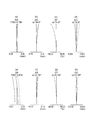
- FIGS. 3A, 3B, 3C and 3D show spherical aberration (SA), astigmatism (AS), distortion aberration (DT), and lateral chromatic aberration in the normal observation state of Example 1, respectively.
- 3 (e), (f), (g), and (h) are spherical aberration (SA), astigmatism (AS), distortion aberration (DT), and lateral chromatic aberration in the magnified observation state of Example 1, respectively.
- the horizontal axis represents the amount of aberration.
- the unit of aberration is mm.
- the unit of aberration is%.
- ⁇ is a half angle of view, the unit is ° (degrees), and FNO is an F number.
- the unit of the wavelength of the aberration curve is nm.
- Example 2 An objective optical system according to Example 2 will be described.
- 4A and 4B are lens cross-sectional views of the objective optical system according to Example 2.
- FIG. 4A is a cross-sectional view in a normal observation state
- FIG. 4B is a cross-sectional view in an enlarged observation state.
- the objective optical system of Example 1 includes, in order from the object side, a first lens group G1 having a positive refractive power, a second lens group G2 having a negative refractive power, and a third lens having a positive refractive power. And group G3.
- the first lens group G1 includes a plano-concave negative lens L1 having a plane on the object side, a positive meniscus lens L2 having a convex surface facing the image side, a negative meniscus lens L3 having a convex surface facing the image side, and a biconvex positive lens L4. And a negative meniscus lens L5 having a convex surface facing the image side.
- a cemented lens is formed by the positive meniscus lens L2 and the negative meniscus lens L3.
- the biconvex positive lens L4 and the negative meniscus lens L5 form a cemented lens.
- the second lens group G2 includes a negative meniscus lens L6 having a convex surface facing the object side and a positive meniscus lens L7 having a convex surface facing the object side.
- the negative meniscus lens L6 and the positive meniscus lens L7 form a cemented lens.
- the brightness stop S is disposed between the first lens group G1 and the second lens group G2. More specifically, the aperture stop S is disposed closest to the object side in the second lens group G2.
- the third lens group G3 includes a positive meniscus lens L8 having a convex surface directed toward the object side, a biconvex positive lens L9, a biconcave negative lens L10, a biconvex positive lens L11, and a negative meniscus having a convex surface directed toward the image side.
- the biconvex positive lens L9 and the biconcave negative lens L10 form a cemented lens.
- a biconvex positive lens L11 and a negative meniscus lens L12 form a cemented lens.
- the first sub lens group SUB1 includes a positive meniscus lens L8.
- the second sub lens unit SUB2 includes a plano-convex positive lens L9, a biconcave negative lens L10, a biconvex positive lens L11, and a negative meniscus lens L12.
- a plane-parallel plate F1 is disposed on the image side of the plano-concave negative lens L1.
- a plane parallel plate F2 is disposed on the image side of the third lens group G3.
- the second lens group G2 and the aperture stop S move together.
- the second lens group G2 and the aperture stop S move to the image side.
- the objective optical system of Example 2 has the above-described basic configuration and also satisfies all conditional expressions (1) to (12).
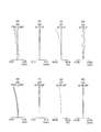
- FIGS. 5A, 5B, 5C, and 5D show spherical aberration (SA), astigmatism (AS), distortion (DT), and lateral chromatic aberration in the normal observation state of Example 2, respectively. It is an aberration diagram of (CC).
- FIGS. 5E, 5F, 5G, and 5H show spherical aberration (SA), astigmatism (AS), distortion aberration (DT), and lateral chromatic aberration in the magnified observation state of Example 2, respectively. It is an aberration diagram of (CC).
- Example 3 An objective optical system according to Example 3 will be described.
- 6A and 6B are lens cross-sectional views of the objective optical system according to Example 3.
- FIG. 6A is a cross-sectional view in a normal observation state
- FIG. 6B is a cross-sectional view in an enlarged observation state.
- the objective optical system of Example 3 includes, in order from the object side, a first lens group G1 having a positive refractive power, a second lens group G2 having a negative refractive power, and a third lens having a positive refractive power. And group G3.
- the first lens group G1 includes a plano-concave negative lens L1 having a plane on the object side, a positive meniscus lens L2 having a convex surface facing the image side, a negative meniscus lens L3 having a convex surface facing the image side, and a biconvex positive lens L4. And a negative meniscus lens L5 having a convex surface facing the image side.
- a cemented lens is formed by the positive meniscus lens L2 and the negative meniscus lens L3.
- the biconvex positive lens L4 and the negative meniscus lens L5 form a cemented lens.
- the second lens group G2 includes a negative meniscus lens L6 having a convex surface facing the object side and a positive meniscus lens L7 having a convex surface facing the object side.
- the negative meniscus lens L6 and the positive meniscus lens L7 form a cemented lens.
- the brightness stop S is disposed between the first lens group G1 and the second lens group G2. More specifically, the aperture stop S is disposed closest to the object side in the second lens group G2.
- the third lens group G3 includes a biconvex positive lens L8, a biconvex positive lens L9, a biconvex positive lens L10, and a biconcave negative lens L11.
- the biconvex positive lens L10 and the biconcave negative lens L11 form a cemented lens.
- the first sub lens group SUB1 includes a positive meniscus lens L8.
- the second sub lens group SUB2 includes a plano-convex positive lens L9, a biconvex positive lens L10, and a biconcave negative lens L11.
- a plane-parallel plate F1 is disposed on the image side of the plano-concave negative lens L1.
- a plane parallel plate F2 is disposed on the image side of the third lens group G3.
- the second lens group G2 and the aperture stop S move together.
- the second lens group G2 and the aperture stop S move to the image side.
- the objective optical system of Example 3 has the above-described basic configuration and satisfies all of conditional expressions (1) to (12).
- FIGS. 7A, 7B, 7C, and 7D show spherical aberration (SA), astigmatism (AS), distortion aberration (DT), and lateral chromatic aberration in the normal observation state of Example 3, respectively. It is an aberration diagram of (CC).
- FIGS. 7E, 7F, 7G, and 7H show spherical aberration (SA), astigmatism (AS), distortion aberration (DT), and lateral chromatic aberration in the magnified observation state of Example 3, respectively. It is an aberration diagram of (CC).
- FIG. 8 is a lens cross-sectional view of the objective optical system according to Example 4, wherein (a) is a cross-sectional view in a normal observation state, and (b) is a cross-sectional view in an enlarged observation state.
- the objective optical system of Example 4 includes, in order from the object side, a first lens group G1 having a positive refractive power, a second lens group G2 having a negative refractive power, and a third lens having a positive refractive power. And group G3.
- the first lens group G1 includes a plano-concave negative lens L1 having a plane on the object side, a positive meniscus lens L2 having a convex surface facing the image side, a negative meniscus lens L3 having a convex surface facing the image side, and a biconvex positive lens L4. And a negative meniscus lens L5 having a convex surface facing the image side.
- the biconvex positive lens L4 and the negative meniscus lens L5 form a cemented lens.
- the second lens group G2 includes a negative meniscus lens L6 having a convex surface facing the object side and a positive meniscus lens L7 having a convex surface facing the object side.
- the negative meniscus lens L6 and the positive meniscus lens L7 form a cemented lens.
- the brightness stop S is disposed between the first lens group G1 and the second lens group G2. More specifically, the aperture stop S is disposed closest to the object side in the second lens group G2.
- the third lens group G3 includes a biconvex positive lens L8, a biconvex positive lens L9, a biconcave negative lens L10, a biconvex positive lens L11, and a biconcave negative lens L12.
- the biconvex positive lens L9 and the biconcave negative lens L10 form a cemented lens.
- the biconvex positive lens L11 and the biconcave negative lens L12 form a cemented lens.
- the first sub-lens group SUB1 includes a positive meniscus lens L8, a plano-convex positive lens L9, and a bi-concave negative lens L10.
- the second sub lens group SUB2 includes a convex positive lens L11 and a biconcave negative lens L12.
- a plane-parallel plate F1 is disposed on the image side of the plano-concave negative lens L1.
- a plane parallel plate F2 and a plane parallel plate F3 are arranged on the image side of the third lens group G3.
- the second lens group G2 and the aperture stop S move together.
- the second lens group G2 and the aperture stop S move to the image side.
- the objective optical system of Example 4 has the above-described basic configuration and also satisfies all conditional expressions (1) to (12).
- FIGS. 9A, 9B, 9C, and 9D show spherical aberration (SA), astigmatism (AS), distortion aberration (DT), and lateral chromatic aberration in the normal observation state of Example 4, respectively. It is an aberration diagram of (CC).
- FIGS. 9 (e), (f), (g), and (h) show spherical aberration (SA), astigmatism (AS), distortion (DT), and lateral chromatic aberration in the magnified observation state of Example 4, respectively. It is an aberration diagram of (CC).
- FIG. 10 is a lens cross-sectional view of the objective optical system according to Example 5.
- FIG. 10A is a cross-sectional view in a normal observation state
- FIG. 10B is a cross-sectional view in an enlarged observation state.
- the objective optical system of Example 5 includes, in order from the object side, a first lens group G1 having a positive refractive power, a second lens group G2 having a negative refractive power, and a third lens having a positive refractive power. And group G3.
- the first lens group G1 includes a plano-concave negative lens L1 having a plane on the object side, a positive meniscus lens L2 having a convex surface facing the image side, a biconvex positive lens L3, and a negative meniscus lens L4 having a convex surface facing the image side. And consist of Here, the biconvex positive lens L3 and the negative meniscus lens L4 form a cemented lens.
- the second lens group G2 is composed of a negative meniscus lens L5 having a convex surface facing the object side and a positive meniscus lens L6 having a convex surface facing the object side.
- the negative meniscus lens L5 and the positive meniscus lens L6 form a cemented lens.
- the brightness stop S is disposed between the first lens group G1 and the second lens group G2. More specifically, the aperture stop S is disposed closest to the object side in the second lens group G2.
- the third lens group G3 includes a biconvex positive lens L7, a biconvex positive lens L8, a biconcave negative lens L9, and a planoconvex positive lens L10 whose image side is a plane.
- the biconvex positive lens L8 and the negative meniscus lens L9 form a cemented lens.
- the first sub lens group SUB1 includes a biconvex positive lens L7, a biconvex positive lens L8, and a biconcave negative lens L9.
- the second sub lens group SUB2 includes a planoconvex positive lens L10.
- a plane-parallel plate F1 is disposed on the image side of the plano-concave negative lens L1.
- a plane parallel plate F2 is disposed on the image side of the third lens group G3.
- the second lens group G2 and the aperture stop S move together.
- the second lens group G2 and the aperture stop S move to the image side.
- the objective optical system of Example 5 has the above-described basic configuration and also satisfies all conditional expressions (1) to (12).
- FIGS. 11A, 11B, 11C, and 11D show spherical aberration (SA), astigmatism (AS), distortion (DT), and lateral chromatic aberration in the normal observation state of Example 5, respectively. It is an aberration diagram of (CC).
- 11E, 11F, 11G, and 11H show spherical aberration (SA), astigmatism (AS), distortion aberration (DT), and lateral chromatic aberration in the magnified observation state of Example 5, respectively.
- r is the radius of curvature of each lens surface
- d is the distance between the lens surfaces
- ne is the refractive index of the e-line of each lens
- ⁇ d is the Abbe number of each lens.
- f is the focal length at the e-line
- Fno is the F number
- ⁇ is the half field angle
- IH is the image height
- OBJ is the object point distance.
- Numerical example 2 Unit mm Surface data Surface number r d ne ⁇ d 1 ⁇ 0.380 1.88815 40.76 2 1.5663 1.000 3 ⁇ 0.480 1.52300 65.13 4 ⁇ 0.123 5 -8.8662 1.643 1.51825 64.14 6 -2.4040 2.890 1.79192 25.68 7 -4.7427 0.032 8 6.8671 0.612 1.74678 49.34 9 -7.1946 0.239 1.93429 18.90 10 -12.1150 Variable 11 (Aperture) ⁇ 0.016 12 8.6769 0.319 1.48915 70.23 13 2.0266 0.363 1.59667 35.31 14 2.7096 Variable 15 3.8880 1.018 1.49846 81.54 16 338.4541 0.522 17 4.7770 1.262 1.77621 49.60 18 -5.0132 0.478 1.93429 18.90 19 11.7885 0.032 20 3.5786 1.805 1.48915 70.23 21 -3.1896
- a first lens group having a positive refractive power, a second lens group having a negative refractive power, and a third lens group having a positive refractive power Focus by moving the second lens group,
- the third lens group includes at least a positive lens and a cemented lens,
- the cemented lens of the third lens group has a positive lens and a negative lens,
- the first sub lens group of the third lens group is located closer to the object side than the predetermined air interval
- the second sub lens group of the third lens group is located on the image side with respect to a predetermined air interval,
- the predetermined air interval is the maximum air interval among the air intervals in the third lens group,
- An objective optical system characterized by satisfying the following conditional expressions (1) and (2).
- fp is the combined focal length from the first lens group to the first sub lens group
- f is the focal length of the entire objective optical system when focusing on a long distance object point
- tt is a predetermined air interval
- the third lens group further includes another positive lens, 6.
- the objective optical system according to any one of Additional Items 1 to 5, wherein the third lens group includes a positive lens, a cemented lens, and another positive lens in order from the object side.
- the third lens group further includes another cemented lens, Another cemented lens has a positive lens and a negative lens,
- the objective lens system according to any one of Additional Items 1 to 5, wherein the third lens group includes, in order from the object side, a positive lens, a cemented lens, and another cemented lens.
- the lens located closest to the image side of the third lens group is a plano-convex lens
- the first lens group includes, in order from the object side, a plano-concave lens having a concave surface facing the image side, a positive meniscus lens having a convex surface facing the image side, a biconvex lens, and a negative meniscus lens having a convex surface facing the image side.
- a biconvex lens and a negative meniscus lens having a convex surface directed toward the image side are cemented.
- the first lens group includes a plano-concave lens having a concave surface facing the image side, a positive meniscus lens having a convex surface facing the image side, a negative meniscus lens having a convex surface facing the image side, a biconvex lens, A negative meniscus lens having a convex surface facing the image side, A positive meniscus lens having a convex surface facing the image side and a negative meniscus lens having a convex surface facing the image side are cemented,
- the objective optical system according to any one of additional items 1 to 11, wherein a biconvex lens and a negative meniscus lens having a convex surface directed toward the image side are cemented.
- the present invention is useful for an objective optical system that is not easily affected by various errors and in which various aberrations are well corrected.
Landscapes
- Physics & Mathematics (AREA)
- Health & Medical Sciences (AREA)
- Life Sciences & Earth Sciences (AREA)
- Optics & Photonics (AREA)
- Surgery (AREA)
- General Physics & Mathematics (AREA)
- Biomedical Technology (AREA)
- Molecular Biology (AREA)
- Pathology (AREA)
- Radiology & Medical Imaging (AREA)
- Biophysics (AREA)
- Engineering & Computer Science (AREA)
- Astronomy & Astrophysics (AREA)
- Heart & Thoracic Surgery (AREA)
- Medical Informatics (AREA)
- Nuclear Medicine, Radiotherapy & Molecular Imaging (AREA)
- Animal Behavior & Ethology (AREA)
- General Health & Medical Sciences (AREA)
- Public Health (AREA)
- Veterinary Medicine (AREA)
- Lenses (AREA)
- Instruments For Viewing The Inside Of Hollow Bodies (AREA)
- Endoscopes (AREA)
- Nonlinear Science (AREA)
Abstract
L'invention concerne un système optique d'objectif qui est rarement sujet à diverses erreurs et qui corrige favorablement chaque type d'aberration. Ce système optique d'objectif comprend, dans l'ordre d'un objet, un premier groupe de lentilles G1 ayant une puissance de réfraction positive, un deuxième groupe de lentilles G2 ayant une puissance de réfraction négative, et un troisième groupe de lentilles G3 ayant une puissance de réfraction positive. Le deuxième groupe de lentilles G2 est déplacé afin d'effectuer une focalisation. Le troisième groupe de lentilles comprend au moins une lentille positive L7 et une lentille collée CL3. La lentille collée CL3 du troisième groupe de lentilles G3 comprend une lentille positive L8 et une lentille négative L9. Un premier groupe de sous-lentilles SUB1 du troisième groupe de lentilles G3 est positionné plus près de l'objet qu'un entrefer prescrit, et un deuxième groupe de sous-lentilles SUB2 du troisième groupe de lentilles G3 est positionné plus près d'une image que l'entrefer prescrit, l'entrefer prescrit étant l'entrefer maximum parmi les entrefers du troisième groupe de lentilles G3. Le système optique d'objectif satisfait les expressions conditionnelles suivantes (1) et (2) : 1.21 < fp / f < 2.42 (1) 0.35 < tt / f < 0.6 (2).
Priority Applications (3)
| Application Number | Priority Date | Filing Date | Title |
|---|---|---|---|
| CN201780026829.0A CN109073865A (zh) | 2016-05-16 | 2017-04-04 | 物镜光学系统 |
| JP2017548321A JP6266189B1 (ja) | 2016-05-16 | 2017-04-04 | 対物光学系 |
| US16/192,304 US10914935B2 (en) | 2016-05-16 | 2018-11-15 | Objective optical system |
Applications Claiming Priority (2)
| Application Number | Priority Date | Filing Date | Title |
|---|---|---|---|
| JP2016098172 | 2016-05-16 | ||
| JP2016-098172 | 2016-05-16 |
Related Child Applications (1)
| Application Number | Title | Priority Date | Filing Date |
|---|---|---|---|
| US16/192,304 Continuation US10914935B2 (en) | 2016-05-16 | 2018-11-15 | Objective optical system |
Publications (1)
| Publication Number | Publication Date |
|---|---|
| WO2017199614A1 true WO2017199614A1 (fr) | 2017-11-23 |
Family
ID=60325120
Family Applications (1)
| Application Number | Title | Priority Date | Filing Date |
|---|---|---|---|
| PCT/JP2017/014122 Ceased WO2017199614A1 (fr) | 2016-05-16 | 2017-04-04 | Système optique d'objectif |
Country Status (4)
| Country | Link |
|---|---|
| US (1) | US10914935B2 (fr) |
| JP (1) | JP6266189B1 (fr) |
| CN (1) | CN109073865A (fr) |
| WO (1) | WO2017199614A1 (fr) |
Cited By (8)
| Publication number | Priority date | Publication date | Assignee | Title |
|---|---|---|---|---|
| WO2019198362A1 (fr) * | 2018-04-11 | 2019-10-17 | オリンパス株式会社 | Système optique d'objectif pour endoscope |
| WO2020174561A1 (fr) * | 2019-02-26 | 2020-09-03 | オリンパス株式会社 | Système optique d'objectif d'endoscope |
| WO2020178885A1 (fr) * | 2019-03-01 | 2020-09-10 | オリンパス株式会社 | Système optique à grand angle et dispositif d'imagerie l'utilisant |
| JPWO2019198348A1 (ja) * | 2018-04-11 | 2021-03-25 | オリンパス株式会社 | 立体内視鏡対物光学系及びそれを備えた内視鏡 |
| US20210181488A1 (en) * | 2019-03-01 | 2021-06-17 | Olympus Corporation | Wide-angle optical system and image pickup apparatus using the same |
| US12066603B2 (en) | 2019-03-01 | 2024-08-20 | Olympus Corporation | Wide-angle optical system including three lens units of −++ refractive powers, and image pickup apparatus using the same |
| US12117602B2 (en) | 2019-03-01 | 2024-10-15 | Olympus Corporation | Wide-angle optical system and image pickup apparatus using the same |
| KR20250011520A (ko) * | 2023-07-14 | 2025-01-21 | 주식회사 영우디에스피 | 대물 렌즈 결합용 튜브 렌즈 광학계 및 이를 포함한 이물질 검사 장치 |
Families Citing this family (5)
| Publication number | Priority date | Publication date | Assignee | Title |
|---|---|---|---|---|
| WO2020215196A1 (fr) * | 2019-04-23 | 2020-10-29 | 北京数字精准医疗科技有限公司 | Système optique d'endoscope |
| JP7291533B2 (ja) * | 2019-05-10 | 2023-06-15 | 株式会社タムロン | 結像光学系及び撮影装置 |
| CN111929852B (zh) * | 2020-10-12 | 2020-12-15 | 瑞泰光学(常州)有限公司 | 摄像光学镜头 |
| CN117355782B (zh) * | 2022-05-05 | 2026-01-09 | 北京小米移动软件有限公司 | 光学系统、以及具备光学系统的拍摄装置 |
| JP7579858B2 (ja) * | 2022-05-05 | 2024-11-08 | 北京小米移動軟件有限公司 | 光学系、及び光学系を備えた撮像装置 |
Citations (7)
| Publication number | Priority date | Publication date | Assignee | Title |
|---|---|---|---|---|
| JPS6144283B2 (fr) * | 1978-12-29 | 1986-10-02 | Olympus Optical Co | |
| JPH06317744A (ja) * | 1993-04-30 | 1994-11-15 | Olympus Optical Co Ltd | 内視鏡対物光学系 |
| JPH11316339A (ja) * | 1998-03-03 | 1999-11-16 | Olympus Optical Co Ltd | 対物光学系 |
| WO2014132494A1 (fr) * | 2013-02-28 | 2014-09-04 | オリンパスメディカルシステムズ株式会社 | Système optique d'objectif |
| JP2015121649A (ja) * | 2013-12-24 | 2015-07-02 | 株式会社タムロン | インナーフォーカス式レンズ |
| WO2016006486A1 (fr) * | 2014-07-11 | 2016-01-14 | オリンパス株式会社 | Système optique d'objectif |
| WO2016056447A1 (fr) * | 2014-10-06 | 2016-04-14 | オリンパス株式会社 | Endoscope |
Family Cites Families (10)
| Publication number | Priority date | Publication date | Assignee | Title |
|---|---|---|---|---|
| JPS60263916A (ja) | 1984-06-13 | 1985-12-27 | Olympus Optical Co Ltd | 内焦式内視鏡対物レンズ |
| JPS6144283A (ja) * | 1984-08-06 | 1986-03-03 | 井関農機株式会社 | 穀粒乾燥機の熱風温度検出装置 |
| JP3765500B2 (ja) | 1993-12-24 | 2006-04-12 | オリンパス株式会社 | 内視鏡用対物レンズ |
| US6252723B1 (en) | 1998-03-03 | 2001-06-26 | Olympus Optical Co., Ltd. | Objective optical system |
| JP4003851B2 (ja) | 1998-03-12 | 2007-11-07 | 株式会社アルバック | 薄膜作成装置およびそのプラズマ源 |
| JP2000267002A (ja) | 1999-03-15 | 2000-09-29 | Olympus Optical Co Ltd | 光学系 |
| JP4653823B2 (ja) | 2008-06-06 | 2011-03-16 | オリンパスメディカルシステムズ株式会社 | 対物光学系 |
| JP5148403B2 (ja) * | 2008-07-28 | 2013-02-20 | オリンパスメディカルシステムズ株式会社 | 内視鏡用対物光学系 |
| US7889440B2 (en) * | 2009-01-30 | 2011-02-15 | Nkon Corporation | Zoom lens, optical apparatus equipped therewith and method for manufacturing the zoom lens |
| JP5601924B2 (ja) | 2010-07-30 | 2014-10-08 | Hoya株式会社 | 内視鏡用変倍光学系、及び内視鏡 |
-
2017
- 2017-04-04 WO PCT/JP2017/014122 patent/WO2017199614A1/fr not_active Ceased
- 2017-04-04 CN CN201780026829.0A patent/CN109073865A/zh active Pending
- 2017-04-04 JP JP2017548321A patent/JP6266189B1/ja active Active
-
2018
- 2018-11-15 US US16/192,304 patent/US10914935B2/en active Active
Patent Citations (7)
| Publication number | Priority date | Publication date | Assignee | Title |
|---|---|---|---|---|
| JPS6144283B2 (fr) * | 1978-12-29 | 1986-10-02 | Olympus Optical Co | |
| JPH06317744A (ja) * | 1993-04-30 | 1994-11-15 | Olympus Optical Co Ltd | 内視鏡対物光学系 |
| JPH11316339A (ja) * | 1998-03-03 | 1999-11-16 | Olympus Optical Co Ltd | 対物光学系 |
| WO2014132494A1 (fr) * | 2013-02-28 | 2014-09-04 | オリンパスメディカルシステムズ株式会社 | Système optique d'objectif |
| JP2015121649A (ja) * | 2013-12-24 | 2015-07-02 | 株式会社タムロン | インナーフォーカス式レンズ |
| WO2016006486A1 (fr) * | 2014-07-11 | 2016-01-14 | オリンパス株式会社 | Système optique d'objectif |
| WO2016056447A1 (fr) * | 2014-10-06 | 2016-04-14 | オリンパス株式会社 | Endoscope |
Cited By (16)
| Publication number | Priority date | Publication date | Assignee | Title |
|---|---|---|---|---|
| JP7047075B2 (ja) | 2018-04-11 | 2022-04-04 | オリンパス株式会社 | 内視鏡対物光学系、撮像装置及び内視鏡 |
| JP7095076B2 (ja) | 2018-04-11 | 2022-07-04 | オリンパス株式会社 | 立体内視鏡対物光学系及びそれを備えた内視鏡 |
| WO2019198362A1 (fr) * | 2018-04-11 | 2019-10-17 | オリンパス株式会社 | Système optique d'objectif pour endoscope |
| JPWO2019198362A1 (ja) * | 2018-04-11 | 2021-02-25 | オリンパス株式会社 | 内視鏡対物光学系、撮像装置及び内視鏡 |
| JPWO2019198348A1 (ja) * | 2018-04-11 | 2021-03-25 | オリンパス株式会社 | 立体内視鏡対物光学系及びそれを備えた内視鏡 |
| WO2020174561A1 (fr) * | 2019-02-26 | 2020-09-03 | オリンパス株式会社 | Système optique d'objectif d'endoscope |
| JP7079892B2 (ja) | 2019-02-26 | 2022-06-02 | オリンパス株式会社 | 内視鏡用対物光学系及び内視鏡 |
| JPWO2020174561A1 (ja) * | 2019-02-26 | 2021-11-04 | オリンパス株式会社 | 内視鏡用対物光学系及び内視鏡 |
| US20210181488A1 (en) * | 2019-03-01 | 2021-06-17 | Olympus Corporation | Wide-angle optical system and image pickup apparatus using the same |
| WO2020178885A1 (fr) * | 2019-03-01 | 2020-09-10 | オリンパス株式会社 | Système optique à grand angle et dispositif d'imagerie l'utilisant |
| JPWO2020178885A1 (ja) * | 2019-03-01 | 2021-09-30 | オリンパス株式会社 | 広角光学系及びそれを備えた撮像装置 |
| US12066603B2 (en) | 2019-03-01 | 2024-08-20 | Olympus Corporation | Wide-angle optical system including three lens units of −++ refractive powers, and image pickup apparatus using the same |
| US12085707B2 (en) | 2019-03-01 | 2024-09-10 | Olympus Corporation | Wide-angle optical system and image pickup apparatus using the same |
| US12117602B2 (en) | 2019-03-01 | 2024-10-15 | Olympus Corporation | Wide-angle optical system and image pickup apparatus using the same |
| KR20250011520A (ko) * | 2023-07-14 | 2025-01-21 | 주식회사 영우디에스피 | 대물 렌즈 결합용 튜브 렌즈 광학계 및 이를 포함한 이물질 검사 장치 |
| KR102896035B1 (ko) * | 2023-07-14 | 2025-12-04 | 주식회사 영우디에스피 | 대물 렌즈 결합용 튜브 렌즈 광학계 및 이를 포함한 이물질 검사 장치 |
Also Published As
| Publication number | Publication date |
|---|---|
| JPWO2017199614A1 (ja) | 2018-06-07 |
| CN109073865A (zh) | 2018-12-21 |
| US10914935B2 (en) | 2021-02-09 |
| US20190086658A1 (en) | 2019-03-21 |
| JP6266189B1 (ja) | 2018-01-24 |
Similar Documents
| Publication | Publication Date | Title |
|---|---|---|
| JP6266189B1 (ja) | 対物光学系 | |
| JP6501984B2 (ja) | 対物光学系 | |
| JP6197147B1 (ja) | 対物光学系 | |
| JP4934233B2 (ja) | 対物光学系 | |
| CN102460266B (zh) | 物镜光学系统 | |
| JP5948530B2 (ja) | 対物光学系 | |
| CN106255912B (zh) | 物镜光学系统 | |
| CN105074531B (zh) | 放大内窥镜光学系统 | |
| JP6484759B2 (ja) | 対物光学系 | |
| JP2014126652A (ja) | 結像光学系 | |
| JP4817551B2 (ja) | ズームレンズ | |
| JP2013054191A (ja) | ズームレンズ | |
| JP5082486B2 (ja) | ズームレンズと、これを有する光学装置 | |
| JP4984608B2 (ja) | ズームレンズ及び撮像装置 | |
| JP5767330B2 (ja) | ズームレンズおよび撮像装置 | |
| JP5866190B2 (ja) | ズームレンズ及び撮像装置 | |
| JP2019086678A (ja) | 対物光学系 | |
| JP2019008251A (ja) | 内視鏡対物光学系 | |
| JP2011242485A (ja) | ズームレンズ |
Legal Events
| Date | Code | Title | Description |
|---|---|---|---|
| ENP | Entry into the national phase |
Ref document number: 2017548321 Country of ref document: JP Kind code of ref document: A |
|
| NENP | Non-entry into the national phase |
Ref country code: DE |
|
| 121 | Ep: the epo has been informed by wipo that ep was designated in this application |
Ref document number: 17799048 Country of ref document: EP Kind code of ref document: A1 |
|
| 122 | Ep: pct application non-entry in european phase |
Ref document number: 17799048 Country of ref document: EP Kind code of ref document: A1 |