WO2017199629A1 - Dispositif de commande de batterie - Google Patents
Dispositif de commande de batterie Download PDFInfo
- Publication number
- WO2017199629A1 WO2017199629A1 PCT/JP2017/014482 JP2017014482W WO2017199629A1 WO 2017199629 A1 WO2017199629 A1 WO 2017199629A1 JP 2017014482 W JP2017014482 W JP 2017014482W WO 2017199629 A1 WO2017199629 A1 WO 2017199629A1
- Authority
- WO
- WIPO (PCT)
- Prior art keywords
- battery
- internal resistance
- voltage
- polarization
- calculation
- Prior art date
- Legal status (The legal status is an assumption and is not a legal conclusion. Google has not performed a legal analysis and makes no representation as to the accuracy of the status listed.)
- Ceased
Links
Images







Classifications
-
- B—PERFORMING OPERATIONS; TRANSPORTING
- B60—VEHICLES IN GENERAL
- B60L—PROPULSION OF ELECTRICALLY-PROPELLED VEHICLES; SUPPLYING ELECTRIC POWER FOR AUXILIARY EQUIPMENT OF ELECTRICALLY-PROPELLED VEHICLES; ELECTRODYNAMIC BRAKE SYSTEMS FOR VEHICLES IN GENERAL; MAGNETIC SUSPENSION OR LEVITATION FOR VEHICLES; MONITORING OPERATING VARIABLES OF ELECTRICALLY-PROPELLED VEHICLES; ELECTRIC SAFETY DEVICES FOR ELECTRICALLY-PROPELLED VEHICLES
- B60L58/00—Methods or circuit arrangements for monitoring or controlling batteries or fuel cells, specially adapted for electric vehicles
- B60L58/10—Methods or circuit arrangements for monitoring or controlling batteries or fuel cells, specially adapted for electric vehicles for monitoring or controlling batteries
- B60L58/12—Methods or circuit arrangements for monitoring or controlling batteries or fuel cells, specially adapted for electric vehicles for monitoring or controlling batteries responding to state of charge [SoC]
-
- B—PERFORMING OPERATIONS; TRANSPORTING
- B60—VEHICLES IN GENERAL
- B60L—PROPULSION OF ELECTRICALLY-PROPELLED VEHICLES; SUPPLYING ELECTRIC POWER FOR AUXILIARY EQUIPMENT OF ELECTRICALLY-PROPELLED VEHICLES; ELECTRODYNAMIC BRAKE SYSTEMS FOR VEHICLES IN GENERAL; MAGNETIC SUSPENSION OR LEVITATION FOR VEHICLES; MONITORING OPERATING VARIABLES OF ELECTRICALLY-PROPELLED VEHICLES; ELECTRIC SAFETY DEVICES FOR ELECTRICALLY-PROPELLED VEHICLES
- B60L3/00—Electric devices on electrically-propelled vehicles for safety purposes; Monitoring operating variables, e.g. speed, deceleration or energy consumption
-
- B—PERFORMING OPERATIONS; TRANSPORTING
- B60—VEHICLES IN GENERAL
- B60L—PROPULSION OF ELECTRICALLY-PROPELLED VEHICLES; SUPPLYING ELECTRIC POWER FOR AUXILIARY EQUIPMENT OF ELECTRICALLY-PROPELLED VEHICLES; ELECTRODYNAMIC BRAKE SYSTEMS FOR VEHICLES IN GENERAL; MAGNETIC SUSPENSION OR LEVITATION FOR VEHICLES; MONITORING OPERATING VARIABLES OF ELECTRICALLY-PROPELLED VEHICLES; ELECTRIC SAFETY DEVICES FOR ELECTRICALLY-PROPELLED VEHICLES
- B60L3/00—Electric devices on electrically-propelled vehicles for safety purposes; Monitoring operating variables, e.g. speed, deceleration or energy consumption
- B60L3/0023—Detecting, eliminating, remedying or compensating for drive train abnormalities, e.g. failures within the drive train
- B60L3/0046—Detecting, eliminating, remedying or compensating for drive train abnormalities, e.g. failures within the drive train relating to electric energy storage systems, e.g. batteries or capacitors
-
- B—PERFORMING OPERATIONS; TRANSPORTING
- B60—VEHICLES IN GENERAL
- B60L—PROPULSION OF ELECTRICALLY-PROPELLED VEHICLES; SUPPLYING ELECTRIC POWER FOR AUXILIARY EQUIPMENT OF ELECTRICALLY-PROPELLED VEHICLES; ELECTRODYNAMIC BRAKE SYSTEMS FOR VEHICLES IN GENERAL; MAGNETIC SUSPENSION OR LEVITATION FOR VEHICLES; MONITORING OPERATING VARIABLES OF ELECTRICALLY-PROPELLED VEHICLES; ELECTRIC SAFETY DEVICES FOR ELECTRICALLY-PROPELLED VEHICLES
- B60L50/00—Electric propulsion with power supplied within the vehicle
- B60L50/50—Electric propulsion with power supplied within the vehicle using propulsion power supplied by batteries or fuel cells
- B60L50/60—Electric propulsion with power supplied within the vehicle using propulsion power supplied by batteries or fuel cells using power supplied by batteries
-
- G—PHYSICS
- G01—MEASURING; TESTING
- G01R—MEASURING ELECTRIC VARIABLES; MEASURING MAGNETIC VARIABLES
- G01R31/00—Arrangements for testing electric properties; Arrangements for locating electric faults; Arrangements for electrical testing characterised by what is being tested not provided for elsewhere
- G01R31/36—Arrangements for testing, measuring or monitoring the electrical condition of accumulators or electric batteries, e.g. capacity or state of charge [SoC]
-
- G—PHYSICS
- G01—MEASURING; TESTING
- G01R—MEASURING ELECTRIC VARIABLES; MEASURING MAGNETIC VARIABLES
- G01R31/00—Arrangements for testing electric properties; Arrangements for locating electric faults; Arrangements for electrical testing characterised by what is being tested not provided for elsewhere
- G01R31/36—Arrangements for testing, measuring or monitoring the electrical condition of accumulators or electric batteries, e.g. capacity or state of charge [SoC]
- G01R31/3644—Constructional arrangements
- G01R31/3648—Constructional arrangements comprising digital calculation means, e.g. for performing an algorithm
-
- G—PHYSICS
- G01—MEASURING; TESTING
- G01R—MEASURING ELECTRIC VARIABLES; MEASURING MAGNETIC VARIABLES
- G01R31/00—Arrangements for testing electric properties; Arrangements for locating electric faults; Arrangements for electrical testing characterised by what is being tested not provided for elsewhere
- G01R31/36—Arrangements for testing, measuring or monitoring the electrical condition of accumulators or electric batteries, e.g. capacity or state of charge [SoC]
- G01R31/374—Arrangements for testing, measuring or monitoring the electrical condition of accumulators or electric batteries, e.g. capacity or state of charge [SoC] with means for correcting the measurement for temperature or ageing
-
- G—PHYSICS
- G01—MEASURING; TESTING
- G01R—MEASURING ELECTRIC VARIABLES; MEASURING MAGNETIC VARIABLES
- G01R31/00—Arrangements for testing electric properties; Arrangements for locating electric faults; Arrangements for electrical testing characterised by what is being tested not provided for elsewhere
- G01R31/36—Arrangements for testing, measuring or monitoring the electrical condition of accumulators or electric batteries, e.g. capacity or state of charge [SoC]
- G01R31/389—Measuring internal impedance, internal conductance or related variables
-
- H—ELECTRICITY
- H01—ELECTRIC ELEMENTS
- H01M—PROCESSES OR MEANS, e.g. BATTERIES, FOR THE DIRECT CONVERSION OF CHEMICAL ENERGY INTO ELECTRICAL ENERGY
- H01M10/00—Secondary cells; Manufacture thereof
- H01M10/42—Methods or arrangements for servicing or maintenance of secondary cells or secondary half-cells
-
- H—ELECTRICITY
- H01—ELECTRIC ELEMENTS
- H01M—PROCESSES OR MEANS, e.g. BATTERIES, FOR THE DIRECT CONVERSION OF CHEMICAL ENERGY INTO ELECTRICAL ENERGY
- H01M10/00—Secondary cells; Manufacture thereof
- H01M10/42—Methods or arrangements for servicing or maintenance of secondary cells or secondary half-cells
- H01M10/425—Structural combination with electronic components, e.g. electronic circuits integrated to the outside of the casing
-
- H—ELECTRICITY
- H01—ELECTRIC ELEMENTS
- H01M—PROCESSES OR MEANS, e.g. BATTERIES, FOR THE DIRECT CONVERSION OF CHEMICAL ENERGY INTO ELECTRICAL ENERGY
- H01M10/00—Secondary cells; Manufacture thereof
- H01M10/42—Methods or arrangements for servicing or maintenance of secondary cells or secondary half-cells
- H01M10/48—Accumulators combined with arrangements for measuring, testing or indicating the condition of cells, e.g. the level or density of the electrolyte
-
- H—ELECTRICITY
- H02—GENERATION; CONVERSION OR DISTRIBUTION OF ELECTRIC POWER
- H02J—ELECTRIC POWER NETWORKS; CIRCUIT ARRANGEMENTS OR SYSTEMS FOR SUPPLYING OR DISTRIBUTING ELECTRIC POWER; SYSTEMS FOR STORING ELECTRIC ENERGY
- H02J7/00—Circuit arrangements for charging or discharging batteries or for supplying loads from batteries
-
- B—PERFORMING OPERATIONS; TRANSPORTING
- B60—VEHICLES IN GENERAL
- B60K—ARRANGEMENT OR MOUNTING OF PROPULSION UNITS OR OF TRANSMISSIONS IN VEHICLES; ARRANGEMENT OR MOUNTING OF PLURAL DIVERSE PRIME-MOVERS IN VEHICLES; AUXILIARY DRIVES FOR VEHICLES; INSTRUMENTATION OR DASHBOARDS FOR VEHICLES; ARRANGEMENTS IN CONNECTION WITH COOLING, AIR INTAKE, GAS EXHAUST OR FUEL SUPPLY OF PROPULSION UNITS IN VEHICLES
- B60K6/00—Arrangement or mounting of plural diverse prime-movers for mutual or common propulsion, e.g. hybrid propulsion systems comprising electric motors and internal combustion engines
- B60K6/20—Arrangement or mounting of plural diverse prime-movers for mutual or common propulsion, e.g. hybrid propulsion systems comprising electric motors and internal combustion engines the prime-movers consisting of electric motors and internal combustion engines, e.g. HEVs
- B60K6/22—Arrangement or mounting of plural diverse prime-movers for mutual or common propulsion, e.g. hybrid propulsion systems comprising electric motors and internal combustion engines the prime-movers consisting of electric motors and internal combustion engines, e.g. HEVs characterised by apparatus, components or means specially adapted for HEVs
- B60K6/28—Arrangement or mounting of plural diverse prime-movers for mutual or common propulsion, e.g. hybrid propulsion systems comprising electric motors and internal combustion engines the prime-movers consisting of electric motors and internal combustion engines, e.g. HEVs characterised by apparatus, components or means specially adapted for HEVs characterised by the electric energy storing means, e.g. batteries or capacitors
-
- B—PERFORMING OPERATIONS; TRANSPORTING
- B60—VEHICLES IN GENERAL
- B60W—CONJOINT CONTROL OF VEHICLE SUB-UNITS OF DIFFERENT TYPE OR DIFFERENT FUNCTION; CONTROL SYSTEMS SPECIALLY ADAPTED FOR HYBRID VEHICLES; ROAD VEHICLE DRIVE CONTROL SYSTEMS FOR PURPOSES NOT RELATED TO THE CONTROL OF A PARTICULAR SUB-UNIT
- B60W10/00—Conjoint control of vehicle sub-units of different type or different function
- B60W10/24—Conjoint control of vehicle sub-units of different type or different function including control of energy storage means
- B60W10/26—Conjoint control of vehicle sub-units of different type or different function including control of energy storage means for electrical energy, e.g. batteries or capacitors
-
- B—PERFORMING OPERATIONS; TRANSPORTING
- B60—VEHICLES IN GENERAL
- B60W—CONJOINT CONTROL OF VEHICLE SUB-UNITS OF DIFFERENT TYPE OR DIFFERENT FUNCTION; CONTROL SYSTEMS SPECIALLY ADAPTED FOR HYBRID VEHICLES; ROAD VEHICLE DRIVE CONTROL SYSTEMS FOR PURPOSES NOT RELATED TO THE CONTROL OF A PARTICULAR SUB-UNIT
- B60W20/00—Control systems specially adapted for hybrid vehicles
- B60W20/10—Controlling the power contribution of each of the prime movers to meet required power demand
- B60W20/13—Controlling the power contribution of each of the prime movers to meet required power demand in order to stay within battery power input or output limits; in order to prevent overcharging or battery depletion
-
- H—ELECTRICITY
- H01—ELECTRIC ELEMENTS
- H01M—PROCESSES OR MEANS, e.g. BATTERIES, FOR THE DIRECT CONVERSION OF CHEMICAL ENERGY INTO ELECTRICAL ENERGY
- H01M10/00—Secondary cells; Manufacture thereof
- H01M10/42—Methods or arrangements for servicing or maintenance of secondary cells or secondary half-cells
- H01M10/425—Structural combination with electronic components, e.g. electronic circuits integrated to the outside of the casing
- H01M2010/4271—Battery management systems including electronic circuits, e.g. control of current or voltage to keep battery in healthy state, cell balancing
-
- Y—GENERAL TAGGING OF NEW TECHNOLOGICAL DEVELOPMENTS; GENERAL TAGGING OF CROSS-SECTIONAL TECHNOLOGIES SPANNING OVER SEVERAL SECTIONS OF THE IPC; TECHNICAL SUBJECTS COVERED BY FORMER USPC CROSS-REFERENCE ART COLLECTIONS [XRACs] AND DIGESTS
- Y02—TECHNOLOGIES OR APPLICATIONS FOR MITIGATION OR ADAPTATION AGAINST CLIMATE CHANGE
- Y02E—REDUCTION OF GREENHOUSE GAS [GHG] EMISSIONS, RELATED TO ENERGY GENERATION, TRANSMISSION OR DISTRIBUTION
- Y02E60/00—Enabling technologies; Technologies with a potential or indirect contribution to GHG emissions mitigation
- Y02E60/10—Energy storage using batteries
-
- Y—GENERAL TAGGING OF NEW TECHNOLOGICAL DEVELOPMENTS; GENERAL TAGGING OF CROSS-SECTIONAL TECHNOLOGIES SPANNING OVER SEVERAL SECTIONS OF THE IPC; TECHNICAL SUBJECTS COVERED BY FORMER USPC CROSS-REFERENCE ART COLLECTIONS [XRACs] AND DIGESTS
- Y02—TECHNOLOGIES OR APPLICATIONS FOR MITIGATION OR ADAPTATION AGAINST CLIMATE CHANGE
- Y02T—CLIMATE CHANGE MITIGATION TECHNOLOGIES RELATED TO TRANSPORTATION
- Y02T10/00—Road transport of goods or passengers
- Y02T10/60—Other road transportation technologies with climate change mitigation effect
- Y02T10/70—Energy storage systems for electromobility, e.g. batteries
-
- Y—GENERAL TAGGING OF NEW TECHNOLOGICAL DEVELOPMENTS; GENERAL TAGGING OF CROSS-SECTIONAL TECHNOLOGIES SPANNING OVER SEVERAL SECTIONS OF THE IPC; TECHNICAL SUBJECTS COVERED BY FORMER USPC CROSS-REFERENCE ART COLLECTIONS [XRACs] AND DIGESTS
- Y02—TECHNOLOGIES OR APPLICATIONS FOR MITIGATION OR ADAPTATION AGAINST CLIMATE CHANGE
- Y02T—CLIMATE CHANGE MITIGATION TECHNOLOGIES RELATED TO TRANSPORTATION
- Y02T10/00—Road transport of goods or passengers
- Y02T10/60—Other road transportation technologies with climate change mitigation effect
- Y02T10/7072—Electromobility specific charging systems or methods for batteries, ultracapacitors, supercapacitors or double-layer capacitors
-
- Y—GENERAL TAGGING OF NEW TECHNOLOGICAL DEVELOPMENTS; GENERAL TAGGING OF CROSS-SECTIONAL TECHNOLOGIES SPANNING OVER SEVERAL SECTIONS OF THE IPC; TECHNICAL SUBJECTS COVERED BY FORMER USPC CROSS-REFERENCE ART COLLECTIONS [XRACs] AND DIGESTS
- Y02—TECHNOLOGIES OR APPLICATIONS FOR MITIGATION OR ADAPTATION AGAINST CLIMATE CHANGE
- Y02T—CLIMATE CHANGE MITIGATION TECHNOLOGIES RELATED TO TRANSPORTATION
- Y02T90/00—Enabling technologies or technologies with a potential or indirect contribution to GHG emissions mitigation
- Y02T90/10—Technologies relating to charging of electric vehicles
- Y02T90/12—Electric charging stations
Definitions
- the present invention relates to a battery control device.
- Battery systems installed in electric vehicles such as electric vehicles (EV), plug-in hybrid vehicles (PHEV), and hybrid vehicles (HEV) detect battery voltage, temperature, and current in order to maximize battery performance. Based on these, a battery control device that calculates the state of charge of the battery (State of Charge: SOC), the state of deterioration (State of Health: SOH), and the power that can be input and output of the battery is provided.
- SOC state of Charge of the battery
- SOH state of deterioration
- SOH state of deterioration
- the internal resistance of the battery increases with deterioration. Therefore, calculate the internal resistance value of the battery in real time and use it to calculate the input / output power of the battery appropriately, or calculate the ratio between the initial internal resistance and the internal resistance after deterioration as SOH, This is used as a guide for battery replacement.
- a method for calculating the internal resistance of the battery there are a method for calculating from the ratio between the battery voltage change amount and the current change amount, and a method for calculating based on an equivalent circuit model in which the resistance component of the battery is modeled.
- Patent Literature 1 discloses a technique for extracting each circuit parameter constituting an equivalent circuit model using an adaptive digital filter based on current and voltage during charging and discharging.
- the battery control device includes an internal resistance calculation unit that calculates the internal resistance value of the battery, and controls the battery based on the internal resistance value calculated by the internal resistance calculation unit.
- An index calculation unit that calculates an index representing the polarization voltage of the battery and a determination unit that determines whether or not the index is equal to or higher than a determination threshold value, and is determined to be equal to or higher than the determination threshold value by the determination unit.
- the battery is controlled based on the internal resistance value calculated when the index is less than the determination threshold value before the determination.
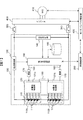
- FIG. 1 is a diagram for explaining the first embodiment.
- FIG. 2 is a diagram illustrating an example of the SOC table.
- FIG. 3 is a diagram illustrating a circuit configuration of the unit cell control unit.
- FIG. 4 is a block diagram illustrating a configuration of the assembled battery control unit.
- FIG. 5 is a block diagram showing a configuration of the SOC calculation unit.
- FIG. 6 is a diagram illustrating an example of a correspondence relationship between the SOC and the OCV.
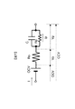
- FIG. 7 is a diagram showing an equivalent circuit of a single battery.
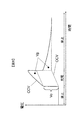
- FIG. 8 is a diagram illustrating the behavior of the voltage when a charging current flows through the single battery represented by the equivalent circuit of FIG.
- FIG. 9 is a block diagram illustrating a configuration of the internal resistance calculation execution determination unit.
- FIG. 1 is a diagram for explaining the first embodiment.
- FIG. 2 is a diagram illustrating an example of the SOC table.
- FIG. 3 is a diagram illustrating a circuit configuration of the unit cell
- FIG. 10 is a diagram for explaining whether or not the internal resistance calculation is possible.
- FIG. 11 is a block diagram illustrating a configuration of the SOH calculation unit.
- FIG. 12 is a diagram illustrating an example of the SOH calculation result.
- FIG. 13 is a block diagram illustrating a configuration of an internal resistance calculation execution determination unit according to the second embodiment.
- FIG. 14 is a diagram illustrating an example of moving average value calculation.
- FIG. 15 is a diagram showing the relaxation behavior of the polarization voltage.
- FIG. 16 is a diagram illustrating an example of the SOH calculation result in the second embodiment.
- FIG. 17 is a block diagram illustrating a configuration of the internal resistance calculation execution determination unit in the second embodiment.
- FIG. 18 is a diagram illustrating an example of the SOH calculation result in the third embodiment.
- FIG. 11 is a block diagram illustrating a configuration of the SOH calculation unit.
- FIG. 12 is a diagram illustrating an example of the SOH calculation result.
- FIG. 13 is
- FIG. 19 is a diagram showing a calculated polarization voltage value and a true polarization voltage value when energized.
- FIG. 20 is a block diagram illustrating a configuration of an internal resistance calculation execution determination unit according to the fourth embodiment.
- FIG. 21 is a diagram illustrating an example of the SOH calculation result in the fourth embodiment.
- FIG. 22 is a block diagram showing the configuration of the assembled battery control unit in the fifth embodiment.
- FIG. 23 is a block diagram illustrating a configuration of an internal resistance calculation execution determination unit according to the fifth embodiment.
- FIG. 24 is a diagram illustrating an example of a data table of polarization determination threshold values in the sixth embodiment.
- the configuration of the embodiment described below can also be applied to a battery control circuit of a battery system that constitutes a power source for an industrial vehicle such as a passenger car such as a plug-in hybrid vehicle (PHEV) or an electric vehicle (EV) or a hybrid railway vehicle. .
- PHEV plug-in hybrid vehicle
- EV electric vehicle
- hybrid railway vehicle a hybrid railway vehicle.
- a lithium ion battery is applied to a battery constituting a power storage unit
- a nickel metal hydride battery, a lead battery, an electric double layer capacitor, a hybrid capacitor, or the like can also be used as the battery.
- FIG. 1 is a diagram for explaining the battery control device according to the first embodiment, and shows a configuration example of an electric system of a hybrid vehicle.
- Battery system 100 is connected to inverter 400 via relays 300 and 310.
- Inverter 400 supplies electric power from battery system 100 to motor generator 410.
- Inverter 400 and motor generator 410 are controlled by motor / inverter controller 420.
- the vehicle control unit 200 determines the distribution of driving force based on battery information such as SOC (State of charge) of the battery system 100, information from the inverter 400 and the motor generator 410, information from an engine (not shown), and the like. To do.
- SOC State of charge
- the configuration of the battery system 100 includes an assembled battery 110 composed of a plurality of unit cells 111, a unit cell management unit 120 that monitors the state of the unit cell 111, a current detection unit 130 that detects a current flowing through the assembled battery 110, and a group.
- a voltage detection unit 140 that detects the total voltage of the battery 110, an assembled battery control unit 150 that controls the assembled battery 110, and a storage unit that stores information on battery characteristics of the assembled battery 110, the single battery 111, and the single battery group 112 180.
- the assembled battery 110 is configured by electrically connecting a plurality of unit cells 111 (for example, lithium ion batteries) capable of storing and releasing electrical energy (charging and discharging DC power) in series.
- unit cells 111 for example, lithium ion batteries
- One unit cell 111 has an output voltage of 3.0 to 4.2 V (average output voltage: 3.6 V).
- OCV Open Circuit Voltage
- the unit cells 111 constituting the assembled battery 110 are grouped into a predetermined number of units when managing and controlling the state of the unit cells 111. In the example shown in FIG. 1, it is grouped into two cell groups 112a and 112b. The grouped unit cells 111 are electrically connected in series to form a unit cell group 112.
- the predetermined number of units may be equal divisions such as 1, 4, 6, etc., or may be combined divisions such as combining 4 and 6 units. is there. In the example shown in FIG. 1, the predetermined number of units is four.
- the single cell management unit 120 monitors the state of the single cells 111 constituting the assembled battery 110 as described above.
- the unit cell management unit 120 includes a plurality of unit cell control units 121a and 121b, and one unit cell control unit 121 is assigned to the unit cell group 112 grouped as described above.
- the unit cell control unit 121 operates by receiving power from the allocated unit cell group 112.
- the unit cell control unit 121 monitors the battery voltage and temperature of the unit cells 111 constituting the unit cell group 112.
- a cell control unit 121a and a cell control unit 121b are provided corresponding to the cell group 112a and the cell group 112b.
- the unit cell group 112 is assumed to have a configuration in which four unit cells 111 are electrically connected in series.
- the single cell controller 121 is configured to monitor.
- the assembled battery control unit 150 is transmitted from the voltage detection unit 140, the battery voltage and temperature of the unit cell 111 transmitted from the unit cell management unit 120, the current value flowing through the assembled battery 110 transmitted from the current detection unit 130, and the voltage detection unit 140.
- a total voltage value of the assembled battery 110, a diagnosis result indicating whether the unit cell 111 is overcharged or overdischarged, and an abnormal signal output when a communication error occurs in the unit cell management unit 120 are input.
- the assembled battery control unit 150 detects the state of the assembled battery 110 based on the input information.
- the result of the process performed by the assembled battery control unit 150 is transmitted to the single cell management unit 120 and the vehicle control unit 200.
- the assembled battery control unit 150 and the single cell management unit 120 perform signal transmission / reception through the signal communication unit 160.
- the signal communication unit 160 is provided with an insulating element 170 such as a photocoupler.
- the insulating element 170 is provided because the operating power supply is different between the assembled battery control unit 150 and the unit cell management unit 120.
- the single cell management unit 120 operates by receiving power from the assembled battery 110, but the assembled battery control unit 150 uses a battery for in-vehicle auxiliary equipment (for example, a 12V battery) as a power source.
- the insulating element 170 may be mounted on a circuit board that constitutes the unit cell management unit 120 or may be mounted on a circuit board that constitutes the assembled battery control unit 150. Depending on the system configuration, the insulating element 170 may be omitted.
- the cell control units 121a and 121b are connected in series according to the order of potential of the cell groups 112a and 112b monitored by each.
- the signal transmitted by the assembled battery control unit 150 is input to the single cell control unit 121a by the signal communication unit 160 provided with the insulating element 170.
- the output of the cell control unit 121a and the input of the cell control unit 121b are connected by the signal communication unit 160, and the signal communication unit 160 transmits a signal.
- the insulating element 170 is not provided between the single cell control unit 121a and the single cell control unit 121b, but the insulating element 170 may be provided.
- the output signal from the cell control unit 121b is transmitted to the input unit of the battery pack control unit 150 by the signal communication unit 160 provided with the insulating element 170.
- the assembled battery control unit 150 and the single cell control units 1211a and 121b are connected in a loop by the signal communication unit 160.
- This loop connection may be referred to as a daisy chain connection, a daisy chain connection, or a random connection.
- the storage unit 180 includes internal resistance characteristics of the assembled battery 110, the single battery 111, and the single battery group 112, capacity at full charge, polarization resistance characteristics, deterioration characteristics, individual difference information, and correspondence between SOC and OCV (SOC table). Such information is stored.
- the storage unit 180 is installed outside the assembled battery control unit 150 or the unit cell management unit 120, but the storage unit is included in the assembled battery control unit 150 or the unit cell management unit 120. It may be provided.
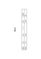
- FIG. 2 is a diagram illustrating an example of the SOC table stored in the storage unit 180.
- the SOC table is a data table in which the correspondence relationship between the OCV of the unit cell 111 and the SOC of the unit cell 111 is described according to the temperature.
- the storage unit 180 stores various battery characteristic information such as internal resistance characteristics and polarization resistance characteristics as a data table in which correspondence relationships with various parameters such as SOC and temperature are described in the same manner as the SOC table.
- the data table is used as the correspondence between the OCV and the SOC.
- the correspondence between the OCV and the SOC may be expressed by an equation or the like, and is not limited to the form of the data table. Absent.
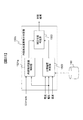
- FIG. 3 is a diagram showing a circuit configuration of the unit cell control unit 121.
- the cell control unit 121 includes a voltage detection circuit 122, a control circuit 123, a signal input / output circuit 124, and a temperature detection unit 125.
- the voltage detection circuit 122 measures the voltage between the terminals of each unit cell 111.
- the temperature detection unit 125 measures the temperature of the cell group 112.
- the control circuit 123 receives the measurement results from the voltage detection circuit 122 and the temperature detection unit 125, and transmits the measurement results to the assembled battery control unit 150 via the signal input / output circuit 124.
- the unit cell control unit 121 is mounted with a circuit configuration for equalizing variations in voltage and SOC between the unit cells 111 caused by self-discharge and variations in consumption current. The description is omitted as it is well known.
- the temperature detection unit 125 measures a single temperature of the single cell group 112 as a whole, and treats the temperature as a representative temperature value of the single cells 111 constituting the single cell group 112. Therefore, the single battery control unit 121 is provided with one temperature detection unit 125.
- the temperature measured by the temperature detection unit 125 is used for various calculations for detecting the state of the cell 111, the cell group 112, or the assembled battery 110.
- the temperature detection part 125 may be provided for every single cell 111, temperature may be measured for every single cell 111, and various calculations may be performed based on the temperature for every single cell 111.
- the configuration of the unit cell control unit 121 becomes complicated accordingly.
- FIG. 3 simply shows the temperature detection unit 125.
- a temperature sensor is installed in the temperature measurement target, the temperature sensor outputs temperature information as a voltage, and the measurement result is transmitted to the signal input / output circuit 124 via the control circuit 123.
- the signal input / output circuit 124 outputs the measurement result to the outside of the unit cell control unit 121.
- a function for realizing this series of flows is implemented in the unit cell control unit 121 as the temperature detection unit 125.
- the voltage detection circuit 122 can also be used to measure temperature information (voltage).
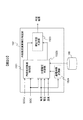
- FIG. 4 is a block diagram showing a configuration of the assembled battery control unit 150.
- FIG. 4 shows a configuration related to the SOC calculation and the SOH calculation related to the battery control in the present embodiment, and for the sake of simplicity, a diagnosis process related to the single battery 111 performed by the assembled battery control unit 150 and a single battery management unit
- the illustration and description of the configuration relating to processing based on an abnormal signal output when a communication error or the like occurs in 120 is omitted.
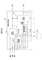
- the assembled battery control unit 150 includes an SOC calculation unit 151, an internal resistance calculation execution determination unit 152, and an SOH calculation unit 153.
- the SOC calculation unit 151 includes the voltage of the unit cells 111 constituting the assembled battery 110 (the average voltage of each unit cell 111), the current flowing through the assembled battery 110, the temperature of the assembled battery 110, and the SOH output by the SOH calculation unit 153. State of Health) is entered.
- the SOC calculation unit 151 calculates and outputs SOC and SOCv based on these inputs. The contents of the SOC and SOCv calculation processing will be described later.
- the internal resistance calculation execution determination unit 152 receives the voltage of the unit cells 111 constituting the assembled battery 110, the current flowing through the assembled battery 110, the temperature of the assembled battery 110, and the aforementioned SOC, SOCv, and SOH. The internal resistance calculation execution determination unit 152 determines whether or not the SOH calculation can be executed based on these inputs, and outputs the determination result. The SOC and SOH calculated by the assembled battery control unit 150 are transmitted to the vehicle control unit 200.
- FIG. 5 is a block diagram showing a configuration of the SOC calculation unit 151.
- the SOC calculation unit 151 includes an SOCi calculation unit 1511, an SOCv calculation unit 1512, and a combination calculation unit 1513.
- the SOCi calculation unit 1511 calculates the SOC based on the integrated value of current (hereinafter referred to as SOCi). Is calculated and output. SOCi is calculated by the following equation (1).
- SOCold is the previous value of SOC calculated by equation (8) described later (calculation result one cycle before).
- ⁇ SOC is the amount of change in the SOC due to the current I flowing from the previous calculation to the current calculation
- Qmax is the full charge capacity of the unit cell 111
- ts is the control cycle (sampling cycle of current, voltage, etc.) ).
- the SOCv calculation unit 1512 calculates an OCV based on the input voltage, current, and temperature, and the SOC corresponding to the calculated OCV (hereinafter referred to as SOCv) from the calculated OCV and the correspondence shown in FIG. ) Is calculated.
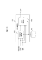
- FIG. 7 is an equivalent circuit diagram of the unit cell 111.
- the unit cell 111 models a DC power source that simulates an OCV that represents the open circuit voltage of the battery, Ro that represents an electrical resistance such as an electrode or an electrolyte, and a resistance component (polarization component) that accompanies the electrochemical reaction of the battery.
- the circuit configuration is such that parallelized Rp and C parallel circuits are connected in series.
- FIG. 8 shows the behavior of the voltage when the charging current I flows through the unit cell 111 represented by the equivalent circuit of FIG.
- a voltage increase Vo I ⁇ Ro
- Vp Ip ⁇ Rp
- Vp Ip ⁇ Rp (3)
- OCV CCV- (Vo + Vp) (4)
- Ro and Rp in the expressions (2) and (3) are the resistance values (RoInit and RpInit) when the unit cell 111 is new as shown in the following expressions (5) and (6). ).
- RoInit and RpInit data tables corresponding to the SOC and temperature are stored in advance in the storage unit 180, and are calculated from the data table based on the current SOC and temperature.
- Ip for example, a result obtained by applying a first-order lag filter to a current value as in the following equation (7) can be used.
- I is a current value
- ts is a sampling period
- ⁇ is a time constant
- Ipold Ip one control period before.
- Ro RoInit ⁇ SOH / 100 (5)
- Rp RpInit ⁇ SOH / 100 (6)
- Ip I ⁇ (ts / ⁇ ) + Ipold ⁇ (1 ⁇ ts / ⁇ ) (7)
- the SOCv calculation unit 1512 calculates the OCV by the above equation (4), and calculates the SOC corresponding to the OCV as the SOCv as shown in FIG.
- SOC Map (OCV)
- Map (OCV) Map (OCV)
- Combination calculation unit 1513 calculates SOC by the following equation (8), using SOCi calculated by SOCi calculation unit 1511, SOCv calculated by SOCv calculation unit 1512, current, and temperature as inputs.
- w represents a weighting coefficient, and is calculated by the following Expression (9), for example.
- the weighting coefficient w as shown in the equation (9) is provided, but the present invention is not limited to this.
- FIG. 9 is a block diagram illustrating a configuration of the internal resistance calculation execution determination unit 152.
- the internal resistance calculation execution determination unit 152 includes an internal resistance error detection unit 1521, a polarization voltage determination unit 1522, and a correction availability determination unit 1523.
- the internal resistance error detection unit 1521 determines whether or not there is an error in the resistance values (Ro, Rp) in the above-described SOCv calculation based on the SOC and SOCv input from the SOC calculation unit 151. Specifically, when the absolute value of the difference between SOC and SOCv is greater than or equal to a predetermined value, it is necessary to correct the internal resistance value (each circuit parameter in the equivalent circuit of FIG. 7) used in the calculation of SOCv. Determine and output the determination result.
- the polarization voltage determination unit 1522 calculates the polarization voltage Vp based on the SOC, current, voltage, and temperature, and determines whether the internal resistance calculation is possible based on the calculated magnitude of the polarization voltage Vp.
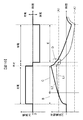
- FIG. 10 is a diagram for explaining whether or not the internal resistance calculation by the polarization voltage determination unit 1522 is possible.
- the broken line L1 indicates the calculated value of the polarization voltage
- the solid line L2 indicates the true value of the polarization voltage.
- the polarization voltage Vp gradually increases with time. At this time, the sign of the polarization voltage Vp is positive. There is a charge / discharge rest state after the charging current is input, but polarization is relaxed in this rest state. However, if the discharge current is applied before the relaxation is completed, the polarization voltage gradually increases in the negative direction over time.
- the difference between the calculated value of the polarization voltage and the true value is small in the initial region B of the energization time.
- the polarization voltage increases and the deviation between the calculated polarization voltage value and the true value also increases (region C).
- the discharge current flows before the polarization voltage is relaxed.
- the influence of the error (calculation error) generated when the charging current is energized remains when the discharge current is energized (region D), and the polarization voltage cannot be accurately calculated when the discharge current is energized (region E). .
- the error in the calculated internal resistance is large, and an error also occurs in the SOH calculation based on the internal resistance. .
- region E the polarization voltage generated during charging remains before the start of discharging, and the polarization voltage is still large, so that the calculation accuracy of the polarization voltage during discharge current conduction cannot be sufficiently secured. It can be judged.
- a predetermined threshold value (A on the positive side, -A on the negative side) is provided for the polarization voltage, and the internal resistance is calculated under the condition that the absolute value of the polarization voltage is large. Do not configure. Furthermore, when the absolute value of the polarization voltage before the current application is greater than or equal to the threshold value, the internal resistance is not calculated during the current application.
- a polarization determination threshold value (hereinafter referred to as a polarization determination threshold value) may be set by passing a current value in consideration of an actual traveling pattern of the vehicle, battery characteristics, and the like, and estimating a polarization voltage generated at that time.
- the polarization voltage Vp which is a voltage change due to the polarization resistance component, may be calculated from the equation (3), or calculated by the following equation (10). You may do it.
- Vp CCV ⁇ Vo ⁇ OCV (10)
- the absolute value of the polarization voltage obtained by the equations (3) and (10) is calculated and used as an index. That is, it is determined whether or not the absolute value
- the correction availability determination unit 1523 determines whether or not to perform the internal resistance correction calculation based on the determination results of the internal resistance error detection unit 1521 and the polarization voltage determination unit 1522. As described above, the internal resistance error detection unit 1521 determines that the internal resistance value needs to be corrected when the absolute value of the difference between the SOC and the SOCv is equal to or greater than a predetermined value. In addition, the polarization voltage determination unit 1522 determines whether or not the absolute value of the polarization voltage is greater than or equal to the polarization determination threshold value. The correction possibility determination unit 1523 corrects the internal resistance when the internal resistance error detection unit 1521 determines that the internal resistance value needs to be corrected and the absolute value of the polarization voltage is less than the polarization determination threshold. It is determined that the calculation should be performed. In other cases, it is determined that the internal resistance correction calculation cannot be executed.
- FIG. 11 is a block diagram showing the configuration of the SOH calculation unit 153.
- the SOH calculation unit 153 includes an internal resistance correction unit 1531 and an SOH calculation unit 1532.
- the internal resistance correction unit 1531 receives the determination result of the internal resistance calculation execution determination unit 152, the SOC, and the temperature.
- the internal resistance correction unit 1531 stores the internal resistance corresponding to the input SOC and temperature from the internal resistance table stored in the storage unit 180. The resistance value is read and the internal resistance value is corrected. The corrected result is output to the SOH calculation unit 1532.
- the following is performed based on the difference between SOC and SOCv.
- the difference (SOC-SOCv) is positive during charging
- the internal resistance value is corrected to be decreased by a predetermined correction amount so that the difference is decreased.
- the difference (SOC-SOCv) is negative during charging
- the internal resistance value is corrected to be increased by a predetermined correction amount.
- the difference (SOC-SOCv) is positive during discharge
- the internal resistance value is corrected to increase by a predetermined correction amount.
- the difference is negative
- the internal resistance value is decreased by a predetermined correction amount.
- the SOH calculation unit 1532 calculates SOH by the following equation (11), for example.
- SOH is the ratio of Ro and RoInit, but may be the ratio of Rp and RpInit.
- SOH 100 ⁇ Ro / RoInit (11)
- the internal resistance correction unit 1531 does not correct the internal resistance value, and the internal resistance before it is determined that the polarization voltage is high. Output the value. For example, when calculation processing is performed along an arbitrary calculation cycle, the internal resistance value calculated in the calculation cycle immediately before the calculation cycle determined to be unexecutable is output. For this reason, the SOH calculated by the above equation (11) is also the SOH before it is determined that the polarization voltage is high.
- the SOH calculated by the SOH calculation unit 1532 is fed back to the SOCv calculation unit 1512 in the SOC calculation unit 151 and used for the calculation of the SOCv in the next calculation cycle.
- the internal resistance value is sequentially corrected so that the difference between the SOC and the SOCv becomes small.
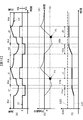
- FIG. 12 is a diagram showing an example of the SOH calculation result.
- FIG. 12A shows time-series data of current (line LI) and voltage (line LV).
- 12B and 12C show the calculation results of the polarization voltage and SOH when the current and voltage shown in FIG. 12A are input. Since the current needs to be energized to execute the internal resistance value correction calculation, the resistance correction calculation is not executed in the idle period when the current is not energized. In this case, the SOH calculation unit 1532 outputs the SOH calculation result immediately before entering the pause.
- the correction operation of the internal resistance value is executed, and the SOH gradually increases.
- the polarization voltage deviates from the polarization determination threshold ( ⁇ A) (the case where
- the correction calculation of the internal resistance value is stopped at the deviating timing, and the polarization
- the internal resistance value before deviating from the determination threshold is output.
- the SOH calculated based on the internal resistance value is not updated while the polarization voltage deviates from the polarization determination threshold value, and the SOH having the same value as the SOH before the polarization determination threshold value is output. .
- the discharge period H1 After the discharge period H1 is stopped, it becomes a rest period, but since the period is short, the polarization voltage before the current is switched is also at the time point P1 (before the discharge current flows) when the current switches from the rest period to the charge period J1. Remains large. Therefore, even if a charging current flows during the charging period J1, the SOH update is stopped, and the SOH before the polarization determination (the SOH at the end of the discharging period H1) is output.
- the previous pause period is long, and at the start of the discharge period H2, the polarization voltage is relaxed to within the range of the polarization determination threshold. Therefore, when the discharge in the discharge period H2 is started, the SOH is updated. However, in the latter period H2b of the discharge period H2, the SOH is not updated because the polarization voltage deviates from the polarization determination threshold ( ⁇ A).
- the SOH is updated as in the charging period J1. Instead, SOH having the same value as the SOH immediately before the charging period J2 is output.
- the assembled battery control unit 150 as the battery control device includes the internal resistance correction unit 1531 that calculates the internal resistance value of the assembled battery 110, and is based on the internal resistance value calculated by the internal resistance correction unit 1531.
- the assembled battery 110 is controlled.
- the polarization voltage determination unit 1522 of the assembled battery control unit 150 calculates an index representing the polarization voltage of the assembled battery 110 and determines whether the calculated index is equal to or greater than a predetermined threshold.
- the polarization voltage Vp calculated based on the formula (3) or the formula (10) is used as an index representing the polarization voltage.
- the polarization voltage Vp is calculated based on at least one of the current, voltage, and temperature flowing through the battery.
- the polarization voltage Vp as an index is determined to be
- the assembled battery 110 is controlled.
- ⁇ A is used to calculate the internal resistance of the battery and the deterioration degree (SOH) of the internal resistance. It becomes possible to suppress a decrease in accuracy.
- the polarization voltage determined based on one or more that is, the polarization voltage Vp as the voltage change due to the polarization resistance component calculated by the equations (3) and (10) is
- the charging period after the start of energization In J1 the battery in the charging period is controlled based on the internal resistance value calculated when it is less than the determination threshold (
- the internal resistance value is calculated based on a difference between two charging states with different calculation methods, for example, a difference between SOC and SOCv, and the internal resistance value is reduced so that the difference between SOC and SOCv becomes small. Is corrected.
- ⁇ A that is, in a situation where the calculation error is large
- the calculated value of the deterioration degree SOH of the battery is kept constant. It is possible to prevent a large deviation from the true value.
- one of the two charge states (SOC, SOCv) is a charge state SOCv calculated based on the open circuit voltage OCV of the battery.
- FIGS. 1 and 1 of the first embodiment A second embodiment of the present invention will be described with reference to FIGS.
- the configuration of the electric system for the hybrid vehicle in the present embodiment is the same as that shown in FIG. 1 of the first embodiment, and the following is a difference from the configuration of the first embodiment. The explanation will be focused on.
- Vp is directly calculated from Expression (3) or Expression (10), and using this as an index, it is determined whether the polarization voltage is equal to or higher than a predetermined value.
- FIG. 13 is a block diagram of the internal resistance calculation execution determination unit 152 in the present embodiment. 9 is different from the internal resistance calculation execution determination unit 152 shown in FIG. 9 only in the configuration of the polarization voltage determination unit 1522a.
- the polarization voltage determination unit 1522 in FIG. 9 calculates the polarization voltage from the equation (3) or the equation (10). However, in the polarization voltage determination unit 1522a of the present embodiment, the current value is input and an arbitrary interval is calculated. A current moving average value is calculated, and this current moving average value is used as a polarization voltage determination index.
- the polarization voltage varies in appearance depending on the history of the current flowing through the battery. Therefore, the magnitude of the polarization voltage can be indirectly determined by looking at the moving average value calculated from the current in a certain section.
- FIG. 14 is a diagram illustrating an example of moving average value calculation.
- a line L30 indicates an instantaneous current
- L31 indicates a moving average current.
- a moving average value of an arbitrary time window Tw is calculated according to the following formula (12), and this is compared with a polarization determination threshold value.
- the polarization determination threshold value may be determined based on the actual traveling pattern and battery characteristics of the vehicle on which the electric system is mounted.
- the moving average value is taken as an example, but as shown in the following equation (13), a result Iave obtained by applying a first-order lag filter to the current value may be used instead of the moving average value.
- I represents a current value
- ts represents a sampling period
- ⁇ represents a time constant
- Iave_old represents Iave one control period before.
- Tw and ⁇ in the expressions (12) and (13) may be variable according to the temperature of the battery.
- FIG. 15 is a diagram showing the relaxation behavior of the polarization voltage according to temperature.
- FIG. 15B shows the transition of the current flowing through the battery
- FIG. 15A shows the transition of the battery voltage (CCV).
- Line L41 shows the case of low temperature, and the polarization relaxation time is t41.
- Line L42 shows the case of normal temperature, and the polarization relaxation time is t42.
- Line L43 shows the case of high temperature, and the polarization relaxation time is t43. It can be seen that the lower the battery temperature, the longer it takes to relax the polarization.
- the current value via the moving average reflecting the relaxation behavior of the polarization voltage or the first-order lag filter is calculated.
- the behavior of the polarization voltage can be expressed more accurately.
- FIG. 16 is a diagram illustrating an example of the SOH calculation result in the second embodiment.
- FIG. 16A shows time-series data of current (line LI) and voltage (line LV).
- FIGS. 16B and 16C show the calculation results of the moving average current and SOH when the current and voltage shown in FIG. 16A are input.
- the resistance correction calculation is not executed in the idle period in which no current flows.
- the SOH calculation result immediately before entering the suspension period is output.
- the correction calculation of the internal resistance value is executed, and the SOH gradually increases.
- the discharge period H1 is in the latter period H1b, the moving average current deviates from the polarization determination threshold ( ⁇ A1), and when it deviates, the correction calculation of the internal resistance value is stopped, and the internal resistance value before deviating from the polarization determination threshold is output. Is done.
- the SOH calculated based on the internal resistance value is not updated while the moving average current deviates from the polarization determination threshold, and the SOH having the same value as the SOH before the deviation from the polarization determination threshold is output.
- the moving average current After the stop of the discharge period H1, it becomes a rest period, but since the period is short, the moving average current also has a polarization determination threshold at the time point P3 (before the discharge current flows) from the rest period to the charge period J1. Deviates. Therefore, even if a charging current flows during the charging period J1, the SOH update is stopped, and the SOH before the polarization determination (the SOH at the end of the discharging period H1) is output.
- the SOH is updated as in the charging period J1.
- the SOH having the same value as the SOH immediately before the charging period J2 is output.
- a value obtained by averaging the current flowing through the battery in time series is used. It was calculated as an index representing the polarization voltage. Then, it is determined whether the polarization voltage is equal to or higher than a predetermined value depending on whether the index is equal to or higher than the polarization determination threshold (whether it deviates from the polarization determination threshold). The correction control is not performed, and the control is performed using the internal resistance calculation value before the predetermined value or more.
- the internal resistance correction calculation is not performed in a situation where the error of the internal resistance correction calculation becomes large, it is possible to suppress a decrease in the calculation accuracy of the internal resistance and the deterioration degree (SOH) of the internal resistance. Further, it is easier to obtain the average value of the current values than when the polarization voltage Vp is calculated.
- FIGS. 1 -Third embodiment- A third embodiment of the present invention will be described with reference to FIGS.
- the configuration of the electric system of the hybrid vehicle in the present embodiment is the same as that shown in FIG. 1 of the first embodiment, and hereinafter the configurations of the first and second embodiments. It demonstrates centering on a different part.
- Vp is directly calculated from Expression (3) or Expression (10), and using this as an index, it is determined whether the polarization voltage is equal to or higher than the polarization determination threshold.
- the second embodiment it is determined whether the polarization voltage is equal to or higher than the polarization determination threshold based on the value of the current flowing through the battery instead of directly calculated Vp.
- this embodiment described below it is possible to determine whether or not the polarization voltage is equal to or higher than a predetermined value by a simpler method than in the first and second embodiments.
- the polarization voltage increases with the passage of current. Therefore, in this embodiment, the energization time of the current is counted, and it is determined whether or not the polarization voltage is greater than or equal to a predetermined value depending on whether or not the counted continuous energization time is greater than or equal to a predetermined value.
- FIG. 17 shows a block diagram of the internal resistance calculation execution determination unit 152 in the present embodiment.
- the difference from the internal resistance calculation execution determination unit 152 in the first and second embodiments is that an energization time measurement unit 1524 is provided.
- the energization time measurement unit 1524 receives current as an input, and counts the continuous energization time when the absolute value of the current is equal to or greater than a predetermined value and only one of charging or discharging continues. The count result is input to the polarization voltage determination unit 1522b.
- the polarization voltage determination unit 1522b determines that the polarization voltage is large when the count result (continuous energization time) is equal to or greater than the polarization determination threshold A2. When it is determined that the polarization voltage is large, the internal resistance correction calculation is not performed, and the internal resistance value before the polarization voltage is determined to be large is calculated as in the first and second embodiments. Output as the internal resistance of the battery.
- FIG. 18 is a diagram illustrating an example of the SOH calculation result in the third embodiment.
- FIG. 18A shows time-series data of current (line LI) and voltage (line LV).
- 18B and 18C show count results (continuous energization time) and SOH calculation results when the current and voltage shown in FIG. 18A are input.
- the resistance correction calculation is not executed in the idle period in which no current flows.
- the SOH calculation result immediately before entering the suspension period is output.
- the internal resistance value correction calculation is executed, and the SOH gradually increases.
- the SOH calculated based on the internal resistance value is not updated while the continuous energization time deviates from the polarization determination threshold, and the SOH having the same value as the SOH before the deviation from the polarization determination threshold is output.
- the internal resistance correction calculation is not performed, and the internal resistance calculation before the continuous energization time becomes equal to or greater than the polarization determination threshold (A2). Since the value is used, as in the case of the first and second embodiments described above, it is possible to suppress a decrease in the calculation accuracy of the internal resistance and the deterioration degree (SOH) of the internal resistance. Furthermore, in the present embodiment, the time during which the current flowing through the battery is energized (continuous energization time) is counted, and based on the counted continuous energization time, it is determined whether the polarization voltage is greater than or equal to the polarization determination threshold. I did it. Therefore, it is possible to appropriately determine whether or not the polarization voltage is equal to or higher than the polarization determination threshold value by a simpler process than in the case of the first embodiment or the second embodiment described above.
- FIGS. 1 -Fourth embodiment- A fourth embodiment of the present invention will be described with reference to FIGS.
- the configuration of the electric system for the hybrid vehicle in the present embodiment is the same as that shown in FIG. 1 of the first embodiment, and the configurations of the first to third embodiments are described below. It demonstrates centering on a different part.
- one parameter is used as a polarization voltage determination index in any case.
- Vp calculated from Expression (3) or Expression (10) is used as an index for determining whether the polarization voltage is equal to or higher than a predetermined value.
- the present embodiment instead of determining the magnitude of the polarization voltage from one parameter, for example, the determination based on the polarization voltage calculated from the expression (3) or the expression (10) in the first embodiment, It is determined whether or not the polarization voltage is large by using together with the determination based on the energization time in the third embodiment.
- FIG. 19 is a diagram illustrating an example in which such a determination cannot be performed accurately.
- FIG. 19 is a diagram showing a calculated polarization voltage and a true polarization voltage during energization (charge / discharge). Due to the error included in the internal resistance value, a divergence occurs between the polarization voltage calculation value (line L51) and the polarization voltage true value (line L52). At the time of discharge, the calculated polarization voltage shifts to the plus side with respect to the true value of the polarization voltage, and at the time of charge, the calculated polarization voltage shifts to the minus side with respect to the true value of the polarization voltage.
- the internal resistance calculation is not performed when the calculated polarization voltage value before the start of energization deviates from the polarization determination threshold as indicated by reference numeral P1 in FIG. It is said. However, if the polarization determination is performed with the polarization voltage at the moment when the current is applied at the start of energization, the polarization determination threshold is deviated due to an error in internal resistance.
- the polarization voltage can be determined without being affected by errors such as current, voltage, and internal resistance value. Therefore, the method of the first embodiment Then, even in a situation where the above-described divergence occurs, it is possible to accurately determine the polarization during energization. However, since the result counted after the current is passed is cleared to zero, it is impossible to determine whether the polarization voltage has relaxed during the rest period when no current is flowing, and the polarization voltage before the current is passed It is not possible to determine whether or not is large.
- a process for determining that the absolute value of the current at the time of polarization voltage determination is equal to or less than a predetermined value is added to the method of the first embodiment for the determination of the polarization voltage at the moment of energization.
- the method of the third embodiment (referred to as second polarization determination) is applied to the polarization voltage determination during energization.
- FIG. 20 is a block diagram illustrating a configuration of the internal resistance calculation execution determination unit 152 in the present embodiment.
- the internal resistance calculation execution determination unit 152 in FIG. 20 has a configuration in which the energization time measurement unit 1524 described in the third embodiment is added to the internal resistance calculation execution determination unit 152 (FIG. 9) in the first embodiment. It has become.
- the energization time count result (continuous energization time) output by the energization time measurement unit 1524 is input to the polarization voltage determination unit 1522c.
- the polarization voltage determination unit 1522c includes a determination result (first polarization determination) based on Vp and current before the current calculated by Expression (10) is applied, and a determination result (second polarization determination) based on the energization time count result. If any of them determines that the internal resistance calculation cannot be performed, it outputs that the calculation cannot be performed as a determination result.
- FIG. 21 is a diagram illustrating an example of the SOH calculation result in the fourth embodiment.
- FIG. 21 (a). The time series data of current (line LI) and voltage (line LV) are shown.
- FIGS. 21B to 21D show calculation results of polarization voltage, continuous energization time, and SOH when the current and voltage shown in FIG. 21A are input.
- the current In order to execute the correction calculation of the internal resistance value, the current needs to be energized. Therefore, the resistance correction calculation is not executed in the idle period in which the current is not energized. Assume that the SOH calculation result immediately before entering the pause is output.
- Vp before the current calculated by the equation (10) is energized, a determination result based on the current (first polarization determination), and a determination result based on the energization time count result (second polarization).
- the determination result that the correction calculation is executed is output from the polarization voltage determination unit 1522c.
- the internal resistance value correction calculation is executed, and the SOH increases as shown in FIG.
- the charging period J1 the count value of the continuous energization time is polarized. Even if it is less than the determination threshold A2, it is determined by the first polarization determination that internal resistance calculation is impossible. As a result, the SOH update is stopped, and the SOH immediately before the polarization determination is output.
- the pause period is long, and the polarization voltage has relaxed to within the polarization determination threshold, so the SOH is updated.
- the count value of the continuous energization time becomes abnormal in the polarization determination threshold A2, so that the internal resistance calculation is disabled and the update of the SOH is stopped.
- the SOH is not updated as in the charging period J1, and the SOH immediately before the polarization determination is output.
- the polarization voltage determination unit 1522c calculates the polarization voltage calculation value by Equation (10) based on the battery voltage, temperature, and current flowing through the battery, and the energization time measurement unit 1524
- the continuous energization time which is the time during which the current flows through the battery, is calculated.
- the continuous energization time is applied as an index of the polarization voltage during energization
- the polarization voltage calculated value is applied as the polarization voltage before the start of energization.
- An indicator can be used.
- the magnitude of the polarization voltage is determined based on these indices, and when the index is equal to or greater than the polarization determination threshold, the battery is controlled based on the internal resistance value calculated before the threshold is exceeded.
- SOH degree of deterioration of the internal resistance
- polarization voltage index is not limited to the above three types as long as the magnitude of the polarization voltage can be determined.
- FIGS. 1 -Fifth embodiment- A fifth embodiment of the present invention will be described with reference to FIGS.
- the configuration of the electric system for the hybrid vehicle in the present embodiment is the same as that shown in FIG. 1 of the first embodiment, and the configurations of the first to fourth embodiments will be described below. It demonstrates centering on a different part.
- SOC and SOCv are used to detect the internal resistance calculation error.
- SOCi in the SOC is the integrated value of current. Is included. Therefore, when an error is included in the current sensor, the current error may be accumulated, and the SOC error may be increased, and accordingly, there is a concern that the internal resistance calculation accuracy is lowered.
- the voltage measurement value and the equivalent circuit model shown in FIG. 7 are used. By comparing with the calculated battery voltage, the internal resistance calculation error was detected and the internal resistance value was corrected.
- FIG. 22 is a block diagram showing the configuration of the assembled battery control unit 150 in the present embodiment.
- the difference from FIG. 4 of the first embodiment is that a battery voltage predicting unit 154 is provided.
- the battery voltage prediction unit 154 calculates a predicted battery voltage value (CCVmodel) as shown in the following equation (14) based on the input current, temperature, SOC, and SOH.
- CCVmodel a predicted battery voltage value as shown in the following equation (14) based on the input current, temperature, SOC, and SOH.
- OCV is calculated from the correspondence between SOC and OCV shown in FIG. 6, and Vo and Vp are calculated from Expressions (2) and (3).
- CCVmodel OCV + Vo + Vp (14)
- FIG. 23 is a block diagram illustrating a configuration of the internal resistance calculation execution determination unit 152a of the assembled battery control unit 150 illustrated in FIG.
- the internal resistance error detection unit 1521a receives the measured voltage and the predicted battery voltage value CCVmodel calculated by the battery voltage prediction unit 154.
- the internal resistance error detection unit 1521a calculates a difference between the battery voltage predicted value CCVmodel and CCV (voltage measurement value), and inputs the calculation result to the correction availability determination unit 1523.
- the polarization voltage determination unit 1522 outputs the polarization voltage determination in any of the first to fourth embodiments described above. Based on the difference input from the internal resistance error detection unit 1521a and the polarization voltage determination input from the polarization voltage determination unit 1522, the correction enable / disable determination unit 1523 outputs a determination result of whether or not the internal resistance calculation can be executed.
- the internal resistance value correction calculation based on the predicted battery voltage CCVmodel and CCV (voltage measurement value) is corrected to reduce the internal resistance value during charging if the difference between the two (CCVmodel ⁇ CCV) is positive. If it is negative, the internal resistance value is corrected to be increased. On the other hand, during discharge, if the difference between the two is positive, correction is made to increase the internal resistance value, and conversely if it is negative, correction is made to decrease the internal resistance value.
- the same effects as those of the first embodiment described above can be obtained. That is, when the polarization voltage increases and exceeds a predetermined threshold value, the internal resistance correction calculation is stopped, and the internal resistance value is controlled to be the internal resistance calculation value before (immediately before) exceeding the threshold value. As a result, it is possible to suppress a decrease in the calculation accuracy of the internal resistance of the battery and the degree of deterioration (SOH) of the internal resistance.
- the error detection method using a voltage instead of the SOC has been described.
- the present invention is not limited to this.
- the resistance value itself may be directly detected.
- the internal resistance initial value R0 of the battery is calculated by the following equation (16).
- R0 (Vo0 + Vp0) / I (16)
- Vo0 I ⁇ RoInit
- Vp0 Ip ⁇ RpInit.
- the effect of suppressing the reduction in the calculation accuracy by determining the polarization voltage can be obtained as in the case of the SOC and the voltage. I can do it.
- FIG. 24 is a diagram for explaining a sixth embodiment of the present invention.
- the polarization determination threshold used in the polarization voltage determination unit 1522 is set to a certain value.
- the magnitude of the polarization voltage and the calculation accuracy vary depending on the state of the battery. For example, as shown in FIG. 15, the lower the battery temperature is, and the higher the deterioration is, the higher the polarization voltage itself becomes.
- the threshold value is set too severely depending on conditions, and there is a possibility that the internal resistance correction calculation is hardly executed.
- the threshold setting is loose, there is a possibility that the internal resistance correction calculation is executed under conditions that should not be executed.
- the polarization determination threshold is made variable according to the state of the battery.
- temperature and SOH which are considered to be particularly affected, will be described as examples.
- FIG. 24 is a diagram illustrating an example of a data table of polarization determination threshold values according to temperature and SOH.
- the horizontal direction is SOH (%)
- the vertical direction is temperature (° C.).
- the polarization determination threshold is set to be larger as SOH is larger, and is set to be larger as temperature is lower. In this way, by using the threshold value data table according to the temperature and SOH, it is possible to accurately determine the polarization voltage even under different conditions of temperature and SOH.
- a data table corresponding to temperature and SOC is used.
- the data table is not limited to this, and may be a data table corresponding to current, SOC, and the like.
- the present embodiment it is possible to suppress a decrease in frequency of internal resistance correction calculation or a decrease in calculation accuracy of internal resistance, which can occur in the first to fifth embodiments in which the polarization determination threshold is constant. It becomes possible.
- the control when the threshold value is exceeded that is, the internal resistance correction calculation is not performed, and the internal resistance calculation value before the threshold value is exceeded. Therefore, it is possible to more accurately perform the control, and it is possible to suppress a decrease in the calculation accuracy of the internal resistance of the battery and the deterioration degree (SOH) of the internal resistance.
- the polarization voltage directly calculated by the equations (3) and (10) described in the first embodiment and the fourth embodiment depends on the temperature and SOH.
- the polarization voltage can be accurately determined even under different conditions of temperature and SOH.
- SYMBOLS 100 Battery system, 110 ... Assembly battery, 111 ... Single battery, 112, 112a, 112b ... Single battery group, 120 ... Single battery management part, 121, 121a, 121b ... Single battery control part, 122 ... Voltage detection circuit, 123 ... Control circuit 124 ... Signal input / output circuit 125 ... Temperature detection unit 130 ... Current detection unit 140 ... Voltage detection unit 150 ... Battery battery control unit 151 ... SOC calculation unit 152, 152a ... Internal resistance calculation execution Determining unit, 153 ... SOH calculating unit, 154 ... battery voltage predicting unit, 160 ... signal communication unit, 170 ... insulating element, 180 ...
Landscapes
- Engineering & Computer Science (AREA)
- Power Engineering (AREA)
- Life Sciences & Earth Sciences (AREA)
- Sustainable Development (AREA)
- Sustainable Energy (AREA)
- Transportation (AREA)
- Mechanical Engineering (AREA)
- General Physics & Mathematics (AREA)
- Physics & Mathematics (AREA)
- Manufacturing & Machinery (AREA)
- Chemical & Material Sciences (AREA)
- Chemical Kinetics & Catalysis (AREA)
- Electrochemistry (AREA)
- General Chemical & Material Sciences (AREA)
- Microelectronics & Electronic Packaging (AREA)
- Secondary Cells (AREA)
- Tests Of Electric Status Of Batteries (AREA)
- Charge And Discharge Circuits For Batteries Or The Like (AREA)
- Electric Propulsion And Braking For Vehicles (AREA)
Abstract
L'invention concerne un dispositif de commande de batterie qui permet d'améliorer la précision servant au calcul de la résistance interne et de l'état de santé (SOH). Le dispositif de commande de batterie est équipé d'une unité de calcul de SOH (153) qui calcule une valeur de résistance interne concernant la batterie, celle-ci étant commandée sur la base de la valeur de résistance interne calculée par l'unité de calcul de SOH (153). Une unité de détermination d'exécution de calcul de résistance interne (152) calcule un indicateur représentant la tension de polarisation de la batterie, et détermine si l'indicateur est égal ou supérieur à une valeur seuil de détermination. Lorsque l'unité de détermination d'exécution de calcul de résistance interne (152) détermine que l'indicateur est égal ou supérieur à la valeur seuil de détermination, la batterie est commandée sur la base d'une valeur de résistance interne qui a été calculée avant la détermination, à un moment où l'indicateur était inférieur à la valeur seuil de détermination.
Priority Applications (4)
| Application Number | Priority Date | Filing Date | Title |
|---|---|---|---|
| JP2018518152A JP6588632B2 (ja) | 2016-05-18 | 2017-04-07 | 電池制御装置 |
| DE112017002072.7T DE112017002072B4 (de) | 2016-05-18 | 2017-04-07 | Batteriesteuervorrichtung |
| CN201780025279.0A CN109874352B (zh) | 2016-05-18 | 2017-04-07 | 电池控制装置 |
| US16/301,899 US10955479B2 (en) | 2016-05-18 | 2017-04-07 | Battery control device |
Applications Claiming Priority (2)
| Application Number | Priority Date | Filing Date | Title |
|---|---|---|---|
| JP2016-099655 | 2016-05-18 | ||
| JP2016099655 | 2016-05-18 |
Publications (1)
| Publication Number | Publication Date |
|---|---|
| WO2017199629A1 true WO2017199629A1 (fr) | 2017-11-23 |
Family
ID=60324895
Family Applications (1)
| Application Number | Title | Priority Date | Filing Date |
|---|---|---|---|
| PCT/JP2017/014482 Ceased WO2017199629A1 (fr) | 2016-05-18 | 2017-04-07 | Dispositif de commande de batterie |
Country Status (5)
| Country | Link |
|---|---|
| US (1) | US10955479B2 (fr) |
| JP (1) | JP6588632B2 (fr) |
| CN (1) | CN109874352B (fr) |
| DE (1) | DE112017002072B4 (fr) |
| WO (1) | WO2017199629A1 (fr) |
Cited By (13)
| Publication number | Priority date | Publication date | Assignee | Title |
|---|---|---|---|---|
| JP2019138673A (ja) * | 2018-02-06 | 2019-08-22 | 古河電気工業株式会社 | 充電可能電池状態検出装置および充電可能電池状態検出方法 |
| JPWO2020246558A1 (fr) * | 2019-06-07 | 2020-12-10 | ||
| CN112650078A (zh) * | 2020-12-14 | 2021-04-13 | 广西玉柴机器股份有限公司 | 一种纯电及增程式电动汽车整车控制器硬件在环仿真系统 |
| WO2021131184A1 (fr) * | 2019-12-26 | 2021-07-01 | ビークルエナジージャパン株式会社 | Dispositif de commande de batterie et système de batterie |
| JPWO2022024885A1 (fr) * | 2020-07-30 | 2022-02-03 | ||
| JP2022178627A (ja) * | 2021-05-20 | 2022-12-02 | 株式会社Gsユアサ | 蓄電素子モデルの生成方法、蓄電素子モデルの生成装置及びプログラム |
| JPWO2022255480A1 (fr) * | 2021-06-04 | 2022-12-08 | ||
| WO2023188723A1 (fr) * | 2022-03-28 | 2023-10-05 | 株式会社日立ハイテク | Procédé de diagnostic d'état de pile rechargeable, et dispositif de diagnostic d'état |
| WO2024014447A1 (fr) * | 2022-07-11 | 2024-01-18 | 古河電気工業株式会社 | Système de mesure de résistance interne, dispositif de mesure de résistance interne et procédé de mesure de résistance interne |
| JP2024509063A (ja) * | 2022-01-25 | 2024-02-29 | エルジー エナジー ソリューション リミテッド | リチウム二次電池の低電圧不良検査方法およびリチウム二次電池の製造方法 |
| JP2024535318A (ja) * | 2022-05-20 | 2024-09-30 | エルジー エナジー ソリューション リミテッド | バッテリー診断方法、その方法を提供するバッテリー診断装置、およびバッテリーシステム |
| JP2024169559A (ja) * | 2021-04-02 | 2024-12-05 | 株式会社デンソー | 均等化装置 |
| US12187263B2 (en) | 2021-04-07 | 2025-01-07 | Subaru Corporation | Vehicle control apparatus |
Families Citing this family (20)
| Publication number | Priority date | Publication date | Assignee | Title |
|---|---|---|---|---|
| JP2018207558A (ja) * | 2017-05-30 | 2018-12-27 | 本田技研工業株式会社 | 車両 |
| JP7276892B2 (ja) * | 2018-05-14 | 2023-05-18 | 三洋電機株式会社 | 管理装置、蓄電システム |
| WO2020026509A1 (fr) * | 2018-07-30 | 2020-02-06 | 日立オートモティブシステムズ株式会社 | Dispositif d'estimation d'état de cellule et dispositif de commande de cellule |
| JP7422670B2 (ja) * | 2018-09-27 | 2024-01-26 | 三洋電機株式会社 | 電源システム、及び管理装置 |
| JP6617189B1 (ja) * | 2018-10-31 | 2019-12-11 | 日本たばこ産業株式会社 | エアロゾル吸引器用の電源ユニット、エアロゾル吸引器、エアロゾル吸引器の電源制御方法、及びエアロゾル吸引器の電源制御プログラム |
| JP7251390B2 (ja) * | 2019-07-30 | 2023-04-04 | 株式会社デンソー | 電子制御装置 |
| KR102742036B1 (ko) * | 2019-10-01 | 2024-12-13 | 주식회사 엘지에너지솔루션 | 배터리 전력 산출 장치 및 방법 |
| CN111458648B (zh) * | 2020-04-16 | 2022-04-08 | 天津力神电池股份有限公司 | 锂离子电池健康状态的在线检测方法 |
| CN115917341A (zh) * | 2020-07-29 | 2023-04-04 | 株式会社日立高新技术 | 电池管理装置、电池管理方法 |
| US11545728B2 (en) * | 2020-11-04 | 2023-01-03 | Ford Global Technologies, Llc | Battery control system for a hybrid or electric vehicle |
| CN113135116A (zh) * | 2021-04-02 | 2021-07-20 | 北京汽车研究总院有限公司 | 电池系统的防过充控制方法、装置及存储介质和电动车 |
| DE102021207467A1 (de) * | 2021-07-14 | 2023-01-19 | Robert Bosch Gesellschaft mit beschränkter Haftung | Verfahren und Vorrichtung zum Betreiben eines Systems zum Bereitstellen von prädizierten Konfidenzintervallen von Alterungszuständen von elektrischen Energiespeichern für mindestens ein Gerät mithilfe von maschinellen Lernverfahren |
| CN114035075A (zh) * | 2021-11-18 | 2022-02-11 | 国网江苏省电力有限公司苏州供电分公司 | 一种基于权重组合法的自动调整电池状态检测方法及系统 |
| DE102021213420A1 (de) | 2021-11-29 | 2023-06-01 | Stodia GmbH | Verfahren und Vorrichtung zur Bestimmung eines Innenwiderstandes von Batteriezellen einer Hochvoltbatterie eines Kraftfahrzeugs |
| CN114750633B (zh) * | 2022-05-06 | 2024-11-08 | 深圳市道通合创数字能源有限公司 | 一种充电管理方法、控制装置、充电桩和充电系统 |
| CN119096154A (zh) * | 2022-05-20 | 2024-12-06 | 株式会社Lg新能源 | 电池诊断方法以及提供该方法的电池诊断装置和电池系统 |
| US12139042B2 (en) * | 2022-08-09 | 2024-11-12 | Ford Global Technologies, Llc | Vehicle control based on battery temperature estimation |
| US20260043859A1 (en) | 2024-08-07 | 2026-02-12 | Kyma Batteries LLC | Systems and methods for a battery odometer with active shock and vibration monitoring |
| US20260043865A1 (en) * | 2024-08-07 | 2026-02-12 | Kyma Batteries LLC | Systems and methods for a battery cell odometer with internal resistance self-test |
| CN119716613B (zh) * | 2024-12-23 | 2025-10-14 | 南京施默生新能源科技有限公司 | 一种基于直流充电桩的汽车动力电池及管理系统的检测方法 |
Citations (3)
| Publication number | Priority date | Publication date | Assignee | Title |
|---|---|---|---|---|
| JP2002238106A (ja) * | 2001-02-14 | 2002-08-23 | Denso Corp | ハイブリッド車の電池状態制御方法 |
| JP2009145065A (ja) * | 2007-12-11 | 2009-07-02 | Toyota Motor Corp | 二次電池の状態検出装置 |
| JP2015227841A (ja) * | 2014-06-02 | 2015-12-17 | 株式会社日本自動車部品総合研究所 | 二次電池の制御装置 |
Family Cites Families (8)
| Publication number | Priority date | Publication date | Assignee | Title |
|---|---|---|---|---|
| JP3747826B2 (ja) | 2001-09-05 | 2006-02-22 | 日産自動車株式会社 | 二次電池の充電率推定装置 |
| DE102005015727A1 (de) * | 2004-04-23 | 2005-11-17 | Robert Bosch Gmbh | Verfahren zur Ermittlung der Ruhespannung einer Speicherbatterie |
| JP2008053126A (ja) * | 2006-08-25 | 2008-03-06 | Mazda Motor Corp | バッテリ劣化判定装置 |
| WO2011045853A1 (fr) * | 2009-10-14 | 2011-04-21 | 株式会社 日立製作所 | Dispositif de commande de batterie et système d'entraînement de moteur |
| WO2014027389A1 (fr) * | 2012-08-13 | 2014-02-20 | 日立ビークルエナジー株式会社 | Dispositif de régulation de pile et système de pile secondaire |
| JP2015010962A (ja) * | 2013-06-28 | 2015-01-19 | 古河電池株式会社 | 蓄電池の劣化判定方法および蓄電池の劣化判定装置 |
| JP5929880B2 (ja) * | 2013-12-09 | 2016-06-08 | 株式会社デンソー | 電池制御装置 |
| JP5888315B2 (ja) * | 2013-12-18 | 2016-03-22 | トヨタ自動車株式会社 | 蓄電システム |
-
2017
- 2017-04-07 JP JP2018518152A patent/JP6588632B2/ja active Active
- 2017-04-07 CN CN201780025279.0A patent/CN109874352B/zh active Active
- 2017-04-07 US US16/301,899 patent/US10955479B2/en active Active
- 2017-04-07 DE DE112017002072.7T patent/DE112017002072B4/de active Active
- 2017-04-07 WO PCT/JP2017/014482 patent/WO2017199629A1/fr not_active Ceased
Patent Citations (3)
| Publication number | Priority date | Publication date | Assignee | Title |
|---|---|---|---|---|
| JP2002238106A (ja) * | 2001-02-14 | 2002-08-23 | Denso Corp | ハイブリッド車の電池状態制御方法 |
| JP2009145065A (ja) * | 2007-12-11 | 2009-07-02 | Toyota Motor Corp | 二次電池の状態検出装置 |
| JP2015227841A (ja) * | 2014-06-02 | 2015-12-17 | 株式会社日本自動車部品総合研究所 | 二次電池の制御装置 |
Cited By (27)
| Publication number | Priority date | Publication date | Assignee | Title |
|---|---|---|---|---|
| JP2019138673A (ja) * | 2018-02-06 | 2019-08-22 | 古河電気工業株式会社 | 充電可能電池状態検出装置および充電可能電池状態検出方法 |
| JPWO2020246558A1 (fr) * | 2019-06-07 | 2020-12-10 | ||
| JP7594528B2 (ja) | 2019-06-07 | 2024-12-04 | ビークルエナジージャパン株式会社 | 電池制御装置 |
| WO2021131184A1 (fr) * | 2019-12-26 | 2021-07-01 | ビークルエナジージャパン株式会社 | Dispositif de commande de batterie et système de batterie |
| JPWO2021131184A1 (fr) * | 2019-12-26 | 2021-07-01 | ||
| US12424673B2 (en) | 2019-12-26 | 2025-09-23 | Vehicle Energy Japan Inc. | Battery control apparatus and battery system |
| JP7605766B2 (ja) | 2019-12-26 | 2024-12-24 | ビークルエナジージャパン株式会社 | 電池制御装置及び電池システム |
| AU2021315194B2 (en) * | 2020-07-30 | 2024-03-07 | Hitachi High-Tech Corporation | Battery pack diagnosing method, cell diagnosing method, battery pack diagnosing device, and cell diagnosing device |
| JPWO2022024885A1 (fr) * | 2020-07-30 | 2022-02-03 | ||
| WO2022024885A1 (fr) * | 2020-07-30 | 2022-02-03 | 株式会社日立ハイテク | Procédé de diagnostic de bloc-batterie, procédé de diagnostic d'élément, dispositif de diagnostic de bloc-batterie et dispositif de diagnostic d'élément |
| JP7538227B2 (ja) | 2020-07-30 | 2024-08-21 | 株式会社日立ハイテク | 電池パックの診断方法、セルの診断方法、電池パックの診断装置及びセルの診断装置 |
| CN112650078A (zh) * | 2020-12-14 | 2021-04-13 | 广西玉柴机器股份有限公司 | 一种纯电及增程式电动汽车整车控制器硬件在环仿真系统 |
| JP2024169559A (ja) * | 2021-04-02 | 2024-12-05 | 株式会社デンソー | 均等化装置 |
| JP7794266B2 (ja) | 2021-04-02 | 2026-01-06 | 株式会社デンソー | 均等化装置 |
| US12187263B2 (en) | 2021-04-07 | 2025-01-07 | Subaru Corporation | Vehicle control apparatus |
| JP2022178627A (ja) * | 2021-05-20 | 2022-12-02 | 株式会社Gsユアサ | 蓄電素子モデルの生成方法、蓄電素子モデルの生成装置及びプログラム |
| WO2022255480A1 (fr) * | 2021-06-04 | 2022-12-08 | ヌヴォトンテクノロジージャパン株式会社 | Dispositif d'estimation d'état de batterie, système d'estimation d'état de batterie et procédé d'estimation d'état de batterie |
| JPWO2022255480A1 (fr) * | 2021-06-04 | 2022-12-08 | ||
| JP7673344B2 (ja) | 2022-01-25 | 2025-05-09 | エルジー エナジー ソリューション リミテッド | リチウム二次電池の低電圧不良検査方法およびリチウム二次電池の製造方法 |
| JP2024509063A (ja) * | 2022-01-25 | 2024-02-29 | エルジー エナジー ソリューション リミテッド | リチウム二次電池の低電圧不良検査方法およびリチウム二次電池の製造方法 |
| EP4276973B1 (fr) | 2022-01-25 | 2025-06-25 | LG Energy Solution, Ltd. | Procédé d'inspection de défaut basse tension dans une batterie secondaire au lithium et procédé de fabrication de batterie secondaire au lithium |
| WO2023188723A1 (fr) * | 2022-03-28 | 2023-10-05 | 株式会社日立ハイテク | Procédé de diagnostic d'état de pile rechargeable, et dispositif de diagnostic d'état |
| JP7660540B2 (ja) | 2022-03-28 | 2025-04-11 | 株式会社日立ハイテク | 二次電池の状態診断方法および状態診断装置 |
| JP2023144673A (ja) * | 2022-03-28 | 2023-10-11 | 株式会社日立ハイテク | 二次電池の状態診断方法および状態診断装置 |
| JP2024535318A (ja) * | 2022-05-20 | 2024-09-30 | エルジー エナジー ソリューション リミテッド | バッテリー診断方法、その方法を提供するバッテリー診断装置、およびバッテリーシステム |
| JP7680141B2 (ja) | 2022-05-20 | 2025-05-20 | エルジー エナジー ソリューション リミテッド | バッテリー診断方法、その方法を提供するバッテリー診断装置、およびバッテリーシステム |
| WO2024014447A1 (fr) * | 2022-07-11 | 2024-01-18 | 古河電気工業株式会社 | Système de mesure de résistance interne, dispositif de mesure de résistance interne et procédé de mesure de résistance interne |
Also Published As
| Publication number | Publication date |
|---|---|
| DE112017002072B4 (de) | 2025-05-15 |
| CN109874352A (zh) | 2019-06-11 |
| JP6588632B2 (ja) | 2019-10-09 |
| CN109874352B (zh) | 2023-03-24 |
| US10955479B2 (en) | 2021-03-23 |
| DE112017002072T5 (de) | 2019-01-03 |
| JPWO2017199629A1 (ja) | 2019-03-14 |
| US20190288344A1 (en) | 2019-09-19 |
Similar Documents
| Publication | Publication Date | Title |
|---|---|---|
| JP6588632B2 (ja) | 電池制御装置 | |
| JP6496810B2 (ja) | 電池制御装置、および電動車両システム | |
| EP3112888B1 (fr) | Système de batterie secondaire | |
| CN113396503B (zh) | 电池控制装置 | |
| US9533597B2 (en) | Parameter identification offloading using cloud computing resources | |
| JP7605766B2 (ja) | 電池制御装置及び電池システム | |
| JP7016704B2 (ja) | 二次電池システム | |
| CN102959791B (zh) | 用于确定多个蓄电池单元的至少一个状态的方法、蓄电池和机动车 | |
| WO2017056732A1 (fr) | Dispositif de commande de batterie et système de batterie | |
| EP3872920B1 (fr) | Dispositif de commande de batterie | |
| JP7741971B2 (ja) | 電池制御装置及び電池制御方法 | |
| KR20250071245A (ko) | 배터리의 충전 상태(soc)를 결정하는 방법 | |
| Spataru | Battery aging diagnosis and prognosis for Hybrid Electrical Vehicles Applications |
Legal Events
| Date | Code | Title | Description |
|---|---|---|---|
| WWE | Wipo information: entry into national phase |
Ref document number: 2018518152 Country of ref document: JP |
|
| 121 | Ep: the epo has been informed by wipo that ep was designated in this application |
Ref document number: 17799063 Country of ref document: EP Kind code of ref document: A1 |
|
| 122 | Ep: pct application non-entry in european phase |
Ref document number: 17799063 Country of ref document: EP Kind code of ref document: A1 |
|
| WWG | Wipo information: grant in national office |
Ref document number: 112017002072 Country of ref document: DE |