WO2017199714A1 - Structure de joint de tension destinée à une maison unitaire - Google Patents
Structure de joint de tension destinée à une maison unitaire Download PDFInfo
- Publication number
- WO2017199714A1 WO2017199714A1 PCT/JP2017/016453 JP2017016453W WO2017199714A1 WO 2017199714 A1 WO2017199714 A1 WO 2017199714A1 JP 2017016453 W JP2017016453 W JP 2017016453W WO 2017199714 A1 WO2017199714 A1 WO 2017199714A1
- Authority
- WO
- WIPO (PCT)
- Prior art keywords
- joint body
- joint
- unit house
- tensile
- floor
- Prior art date
- Legal status (The legal status is an assumption and is not a legal conclusion. Google has not performed a legal analysis and makes no representation as to the accuracy of the status listed.)
- Ceased
Links
Images




Classifications
-
- E—FIXED CONSTRUCTIONS
- E04—BUILDING
- E04B—GENERAL BUILDING CONSTRUCTIONS; WALLS, e.g. PARTITIONS; ROOFS; FLOORS; CEILINGS; INSULATION OR OTHER PROTECTION OF BUILDINGS
- E04B1/00—Constructions in general; Structures which are not restricted either to walls, e.g. partitions, or floors or ceilings or roofs
- E04B1/343—Structures characterised by movable, separable, or collapsible parts, e.g. for transport
- E04B1/344—Structures characterised by movable, separable, or collapsible parts, e.g. for transport with hinged parts
- E04B1/3441—Structures characterised by movable, separable, or collapsible parts, e.g. for transport with hinged parts with articulated bar-shaped elements
-
- E—FIXED CONSTRUCTIONS
- E04—BUILDING
- E04B—GENERAL BUILDING CONSTRUCTIONS; WALLS, e.g. PARTITIONS; ROOFS; FLOORS; CEILINGS; INSULATION OR OTHER PROTECTION OF BUILDINGS
- E04B1/00—Constructions in general; Structures which are not restricted either to walls, e.g. partitions, or floors or ceilings or roofs
- E04B1/38—Connections for building structures in general
- E04B1/58—Connections for building structures in general of bar-shaped building elements
Definitions
- the present invention relates to a unit house tensile joint structure in which a beam is tension-joined to a unit house column.
- Patent Document 1 discloses a column / beam joint structure joined by rivets. In this joining structure, the reinforcement plate and the end plate are used in an overlapping manner to prevent column deformation and the like.
- Patent Document 2 describes a connecting structure of steel materials that are connected to a connecting side surface between a column and a beam via an end plate.
- a substantially T-shaped, substantially U-shaped, or rectangular end plate is joined to the connection part, and the inside of the side surface of the column joining the end plate is reinforced. . That is, the reinforcing plate is welded to each of the opening end portion of the steel material used as the column and the inside of the side surface with which the beam abuts to prevent the column from being deformed.
- connection structure described in Patent Document 2 in order to reinforce the side surface portion of the column, it is necessary to weld the reinforcing plate to the inside of the side surface against which the beam abuts to prevent deformation of the column.
- the column material was limited to a grooved steel or C-shaped steel capable of connecting a reinforcing plate to the inside of the side surface of the column. Therefore, this connection structure is a structure that cannot be adopted for a unit house that uses a columnar material other than a grooved steel or C-shaped steel, such as a prismatic columnar column.
- An object of the present invention is to provide a unit house tensile joint structure capable of rationalizing the work at the time of assembling the house.
- the first means in the present invention is to tension-join the floor beam 4 and the roof beam 5 with the connecting bolt 20 and the connecting nut 30 above and below the column frame 1 erected at the time of assembling the unit house P.
- a unit house tensile joint structure A structure in which a steel box-like joint body 10 is welded to the upper and lower ends of the column frame 1 and the floor beam 4 and the roof beam 5 are tension-bonded to the side surface of the joint body 10. is there.
- the joint body 10 has a box shape in which the side plate 11 surrounds the top plate 12 and the bottom plate 13, and a work window 14 for joining the outdoor side surface of the joint body 10. Is formed, and the top plate 12 or the bottom plate 13 is welded to the end of the column frame 1 in a state where the top plate 12 or the bottom plate 13 is in contact with the upper and lower ends of the column frame 1.
- the third means is to project a guide piece 15 in the direction of the floor beam 4 from the side plate 11 on the indoor side of the joint body 10 to which the floor beam 4 is tension-joined, and the guide piece 15 is attached to the floor beam 4.
- the stacking body 10 is configured to be introduced into the joint position of the floor beam 4 when stacked along the longitudinal side surface.
- the fourth means is to form a notch recess 16 in the upper end portion of the flange side plate 11 of the joint body 10 to which the roof beam 5 is tension-joined, and to support the roof panel 6 supported by the roof beam 5.
- the cutout recess 16 is configured to be housed inside.
- the joint body 10 in the form of a steel box is welded to the upper and lower ends of the column frame 1, and the floor beam 4 and the roof beam 5 are tension-bonded to the side surface of the joint body 10.
- the joining structure is formed only by welding the joint body 10 provided in advance to the end of the column frame 1, so that the attaching operation of the joining structure becomes extremely easy.
- it since it has a simple structure in which the joint body 10 is welded to the upper and lower end portions of the column frame 1, not only the prismatic columnar column material but also the shape of the column material such as the channel steel or C-shaped steel is used. It is possible to attach the body 10.
- the joint body 10 has a box shape in which the side plate 11 surrounds the top plate 12 and the bottom plate 13, the joint body 10 can obtain extremely high joint strength.
- the work window 14 for joining work is formed on the outer side surface of the joint body 10, the joining work at the time of tensile joining with the connecting bolt 20 and the connecting nut 30 is facilitated.
- the top plate 12 or the bottom plate 13 is welded to the end portion of the column frame 1 in contact with the upper and lower ends of the column frame 1, the welded joint 10 and the column frame 1 are welded. Work can be done easily.
- a guide piece 15 is projected in the direction of the floor beam 4 from the side plate 11 on the indoor side of the joint 10 to which the floor beam 4 is tension-joined, and the guide piece 15 is extended along the longitudinal side surface of the floor beam 4. Since the joint body 10 is configured to be introduced at the joint position of the floor beam 4 when they are overlapped, the joint position of the floor beam 4 and the joint body 10 can be adjusted accurately and quickly. As a result, the work for assembling the unit house can be streamlined.
- a notch recess 16 is formed in the upper end portion of the end side plate 11 of the joint body 10 to which the roof beam 5 is tension-joined, and the notch is formed on the inner side of the end side of the roof panel 6 supported by the roof beam 5. Since the concave portion 16 is configured to be accommodated, the joint body 10 on the roof beam 5 side can be joined so as not to stand out. Therefore, it can also be used as a joining structure of a unit house P that draws attention such as a store, an office, and a showroom.
- the mounting work is easy and accurate joining is possible, and the work at the time of assembling the unit house is streamlined. Achieved the initial goal of being able to.
- the present invention relates to a tensile joint structure of a unit house P that is produced at a factory and assembled locally.
- the unit house P of the present invention has a lower end beam 2 fixed to the lower end portion of the column frame 1 and a upper end beam 3 fixed to the upper end portion of the column frame 1 during transportation.
- the pillar frame 1 is folded and conveyed in a compact state (see FIG. 2).
- the column frame 1 is folded on the floor panel 7 incorporated in the floor beam 4, and the roof panel 6 incorporated in the roof beam 5 is conveyed in a stacked state.
- the floor beam 4 and the roof beam 5 are tensioned and joined to the top and bottom of the standing column frame 1 (see FIG. 3).
- the lower end beam 2 and the upper end beam 3 are already welded to the column frame 1, when the floor beam 4 and the roof beam 5 are joined to the column frame 1, the skeleton of the unit house P is assembled.
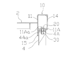
- connection bolt 20 and a connection nut 30 Screw in (see Fig. 4).
- the joint body 10 in the form of a steel box is welded to the upper and lower ends of the column frame 1 in advance. And it is comprised so that the junction edge part of the floor beam 4 and the roof beam 5 may be tension-joined by the connection bolt 20 penetrated by the bolt insertion hole 11Aa opened on the side surface of this joint body 10 (FIG. 4). FIG. 5).
- the illustrated joint body 10 has a box shape in which the side plate 11 surrounds the top plate 12 and the bottom plate 13 (see FIG. 1). At this time, a reinforced side plate 11A in which the side plate 11 through which the connecting bolt 20 is inserted is formed thicker than the other side plates 11 is provided, and the joining plate 4A provided at the joining end of the floor beam 4 (see FIG. 4), the roof beam 5 A joining plate 5A provided at the joining end is tension-joined (see FIG. 5).
- Bolt insertion holes 4Aa and 5Aa are opened in the joining plates 4A and 5A of the floor beam 4 and the roof beam 5 (see FIG. 3). Then, the connecting bolts 20 are inserted into the bolt inserting holes 4Aa and 5Aa from the bolt inserting holes 11Aa opened in the reinforced side plate 11A, and are screwed with the connecting nuts 30 to be joined by tension (see FIGS. 4 and 5).
- a work window 14 for joining work is formed on the side of the outdoor side of the joint 10 (see FIG. 3).
- the work window 14 is formed so that a tool or the like can be easily inserted when the floor beam 4 or the roof beam 5 is screwed to the joint body 10 with the connecting bolt 20.
- symbol 17 of FIG. 3 shows a reinforcement board, and further improves the intensity
- the top plate 12 or the bottom plate 13 of the joint body 10 is welded to the end of the column frame 1 in contact with the upper and lower ends of the column frame 1 (see FIG. 3). By welding in this way, the positioning of the joint body 10 and the column frame 1 is facilitated, and the column frame 1 and the joint body 10 can be welded in a stable state. Becomes easier.
- a guide piece 15 is projected from the side surface of the side plate 11 to which the floor beam 4 is tension-bonded (see FIG. 3).
- the illustrated guide piece 15 is formed by extending the indoor side plate 11 of the joint 10 and is provided so as to contact the indoor side surface of the floor beam 4. And when this guide piece 15 is piled up along the longitudinal side surface of the floor beam 4, it is comprised so that the joint body 10 may be introduce
- the guide piece 15 is simply aligned with the side surface of the floor beam 4. (See FIG. 3).
- the guide piece 15 shown in the figure has a hole 15A.
- This sinus hole 15 ⁇ / b> A is a portion into which a Shino etc. is inserted when aligning the joint body 10 with the joining plate 4 ⁇ / b> A of the floor beam 4.
- a notch recess 16 is formed in the side plate 11 to which the roof beam 5 is tension bonded (see FIG. 3). And it is comprised so that this notch recessed part 16 may be accommodated inside the roof panel 6 supported by the roof beam 5 (refer FIG. 6).
- the roof beam 5 is swingably connected to the column frame 1 in advance during transportation (see FIG. 2). Therefore, when the column frame 1 is erected vertically, the joint 10 at the upper end of the column frame 1 and the joint end of the roof beam 5 automatically match (see FIG. 5). At this time, this notch recess 16 is configured to be housed in the end of the end of the roof panel 6 supported by the roof beam 5 (see FIG. 6).
- the joint body 10 and the column frame 1 are not easily noticeable by configuring so that the joining end portion of the upper end portion of the column frame 1 does not protrude from the end of the roof panel 6. As a result, it can be used as a joining structure of the unit house P with high design.
- this invention joining structure is not limited to the example of illustration,
- the structure and shape of the column frame 1, the lower end beam 2, the upper end beam 3, the floor beam 4, the roof beam 5, etc. can be changed arbitrarily.
- design changes can be freely made without changing the gist of the present invention.
Landscapes
- Engineering & Computer Science (AREA)
- Architecture (AREA)
- Physics & Mathematics (AREA)
- Electromagnetism (AREA)
- Civil Engineering (AREA)
- Structural Engineering (AREA)
- Joining Of Building Structures In Genera (AREA)
Abstract
La présente invention vise à fournir une structure de joint de tension destinée à une maison unitaire, avec laquelle un travail de fixation est simple, une liaison précise est possible, et le travail impliqué lors de l'assemblage de la maison unitaire peut être rationalisé. À cet effet, des poutres de pignon inférieures (2) sont fixées aux extrémités inférieures de cadres de colonne (1. Des poutres de pignon supérieures (3) sont fixées aux extrémités supérieures des cadres de colonne (1). Les cadres de colonne (1) sont pliés sur un panneau de plancher (6) dans cet état pendant le transport. Les cadres de colonne (1) sont placés verticalement pendant l'assemblage. Des poutres de plancher (4) et des poutres de toit (5) sont reliées par tension aux sommets et aux fonds des cadres de colonne (1). Des corps de joint en acier en forme de boîte (10) sont soudés aux extrémités supérieures et inférieures des cadres de colonne (1). Les poutres de plancher (4) et les poutres de toit (5) sont reliées par tension aux surfaces latérales des corps de joint (10).
Applications Claiming Priority (2)
| Application Number | Priority Date | Filing Date | Title |
|---|---|---|---|
| JP2016-002294U | 2016-05-19 | ||
| JP2016002294U JP3205531U (ja) | 2016-05-19 | 2016-05-19 | ユニットハウス用引張接合構造 |
Publications (1)
| Publication Number | Publication Date |
|---|---|
| WO2017199714A1 true WO2017199714A1 (fr) | 2017-11-23 |
Family
ID=56513265
Family Applications (1)
| Application Number | Title | Priority Date | Filing Date |
|---|---|---|---|
| PCT/JP2017/016453 Ceased WO2017199714A1 (fr) | 2016-05-19 | 2017-04-26 | Structure de joint de tension destinée à une maison unitaire |
Country Status (2)
| Country | Link |
|---|---|
| JP (1) | JP3205531U (fr) |
| WO (1) | WO2017199714A1 (fr) |
Cited By (2)
| Publication number | Priority date | Publication date | Assignee | Title |
|---|---|---|---|---|
| CN112302160A (zh) * | 2020-11-10 | 2021-02-02 | 江苏沪邦建材有限公司 | 一种装配式框架模块房屋 |
| WO2022057244A1 (fr) * | 2020-09-21 | 2022-03-24 | 昊恒(福建)建材科技有限公司 | Unité de raccordement destinée à un bâtiment préfabriqué |
Citations (7)
| Publication number | Priority date | Publication date | Assignee | Title |
|---|---|---|---|---|
| JPS5398121A (en) * | 1977-02-07 | 1978-08-28 | Jungbluth Otto | Solid supporting mechanism made up of rail and combination body |
| JPS5679501U (fr) * | 1979-11-24 | 1981-06-27 | ||
| JPS6113058B2 (fr) * | 1984-05-31 | 1986-04-11 | Nat House Ind | |
| JPS62125139A (ja) * | 1986-06-10 | 1987-06-06 | 旭化成株式会社 | 鉄骨架構体形成用柱体 |
| JP2001107453A (ja) * | 1999-10-06 | 2001-04-17 | Dai Ichi High Frequency Co Ltd | 通し柱の製造方法 |
| JP2006063587A (ja) * | 2004-08-25 | 2006-03-09 | Takenaka Komuten Co Ltd | 木質構造材による柱梁架構の接合工法及び接合構造 |
| JP2013119718A (ja) * | 2011-12-07 | 2013-06-17 | Misawa Homes Co Ltd | 連結金具の接合構造 |
-
2016
- 2016-05-19 JP JP2016002294U patent/JP3205531U/ja not_active Expired - Lifetime
-
2017
- 2017-04-26 WO PCT/JP2017/016453 patent/WO2017199714A1/fr not_active Ceased
Patent Citations (7)
| Publication number | Priority date | Publication date | Assignee | Title |
|---|---|---|---|---|
| JPS5398121A (en) * | 1977-02-07 | 1978-08-28 | Jungbluth Otto | Solid supporting mechanism made up of rail and combination body |
| JPS5679501U (fr) * | 1979-11-24 | 1981-06-27 | ||
| JPS6113058B2 (fr) * | 1984-05-31 | 1986-04-11 | Nat House Ind | |
| JPS62125139A (ja) * | 1986-06-10 | 1987-06-06 | 旭化成株式会社 | 鉄骨架構体形成用柱体 |
| JP2001107453A (ja) * | 1999-10-06 | 2001-04-17 | Dai Ichi High Frequency Co Ltd | 通し柱の製造方法 |
| JP2006063587A (ja) * | 2004-08-25 | 2006-03-09 | Takenaka Komuten Co Ltd | 木質構造材による柱梁架構の接合工法及び接合構造 |
| JP2013119718A (ja) * | 2011-12-07 | 2013-06-17 | Misawa Homes Co Ltd | 連結金具の接合構造 |
Cited By (3)
| Publication number | Priority date | Publication date | Assignee | Title |
|---|---|---|---|---|
| WO2022057244A1 (fr) * | 2020-09-21 | 2022-03-24 | 昊恒(福建)建材科技有限公司 | Unité de raccordement destinée à un bâtiment préfabriqué |
| CN112302160A (zh) * | 2020-11-10 | 2021-02-02 | 江苏沪邦建材有限公司 | 一种装配式框架模块房屋 |
| CN112302160B (zh) * | 2020-11-10 | 2024-05-28 | 上海晋永建筑科技有限公司 | 一种装配式框架模块房屋 |
Also Published As
| Publication number | Publication date |
|---|---|
| JP3205531U (ja) | 2016-07-28 |
Similar Documents
| Publication | Publication Date | Title |
|---|---|---|
| KR101534443B1 (ko) | 변단면 천정보를 갖는 모듈러 유닛 및 이를 이용한 모듈러 유닛 구조물 | |
| JP6638368B2 (ja) | 接合構造 | |
| JP3205531U (ja) | ユニットハウス用引張接合構造 | |
| JP5271739B2 (ja) | 屋上付帯構造物及びユニット建物 | |
| JP2010281192A (ja) | 建築用接合金具、固定金具、及び、固定ピン | |
| JP2908756B2 (ja) | 梁補強構造および補強金物 | |
| JP7034868B2 (ja) | 柱梁接合構造 | |
| JP4656516B2 (ja) | 既存鋼製構造物の補強方法 | |
| JPH0197739A (ja) | 方形断面である構築部材の接合方法 | |
| JP5380686B2 (ja) | 扉枠の取り付け施工工法 | |
| JP3827242B2 (ja) | 鉄骨構造物の屋根受け部における柱梁継手構造 | |
| JP6564606B2 (ja) | 木・鋼重ね梁構造 | |
| KR102068640B1 (ko) | Lts 조인트 방법 | |
| JP2012072562A (ja) | 中空角材の接合構造、及び浴室ユニット設置台 | |
| JP3859787B2 (ja) | 柱・柱接合方法およびその建方用荒組治具 | |
| KR20210077463A (ko) | 기둥과 보의 연결 구조체 | |
| JP2017110355A (ja) | 床根太の接合構造 | |
| JP2005163454A (ja) | 梁受け金物 | |
| JPH05263476A (ja) | 柱・梁接合構造およびユニットボックス | |
| KR102729164B1 (ko) | 컨트롤 센터 캐비닛용 프레임워크 | |
| JP2006089914A (ja) | 横架材の接合装置 | |
| JP2544284B2 (ja) | 無溶接トラス | |
| JP2010006128A (ja) | トラックのバン型ボディ | |
| JP4735496B2 (ja) | 柱と梁の接合構造 | |
| JPH10204991A (ja) | 柱の接合装置 |
Legal Events
| Date | Code | Title | Description |
|---|---|---|---|
| NENP | Non-entry into the national phase |
Ref country code: DE |
|
| 121 | Ep: the epo has been informed by wipo that ep was designated in this application |
Ref document number: 17799144 Country of ref document: EP Kind code of ref document: A1 |
|
| 122 | Ep: pct application non-entry in european phase |
Ref document number: 17799144 Country of ref document: EP Kind code of ref document: A1 |