WO2017199959A1 - Procédé et dispositif de traitement pour traiter une surface - Google Patents
Procédé et dispositif de traitement pour traiter une surface Download PDFInfo
- Publication number
- WO2017199959A1 WO2017199959A1 PCT/JP2017/018377 JP2017018377W WO2017199959A1 WO 2017199959 A1 WO2017199959 A1 WO 2017199959A1 JP 2017018377 W JP2017018377 W JP 2017018377W WO 2017199959 A1 WO2017199959 A1 WO 2017199959A1
- Authority
- WO
- WIPO (PCT)
- Prior art keywords
- inspection
- processing
- shot
- processing object
- detection element
- Prior art date
- Legal status (The legal status is an assumption and is not a legal conclusion. Google has not performed a legal analysis and makes no representation as to the accuracy of the status listed.)
- Ceased
Links
Images


Classifications
-
- B—PERFORMING OPERATIONS; TRANSPORTING
- B24—GRINDING; POLISHING
- B24C—ABRASIVE OR RELATED BLASTING WITH PARTICULATE MATERIAL
- B24C1/00—Methods for use of abrasive blasting for producing particular effects; Use of auxiliary equipment in connection with such methods
- B24C1/10—Methods for use of abrasive blasting for producing particular effects; Use of auxiliary equipment in connection with such methods for compacting surfaces, e.g. shot-peening
-
- G—PHYSICS
- G01—MEASURING; TESTING
- G01B—MEASURING LENGTH, THICKNESS OR SIMILAR LINEAR DIMENSIONS; MEASURING ANGLES; MEASURING AREAS; MEASURING IRREGULARITIES OF SURFACES OR CONTOURS
- G01B7/00—Measuring arrangements characterised by the use of electric or magnetic techniques
- G01B7/34—Measuring arrangements characterised by the use of electric or magnetic techniques for measuring roughness or irregularity of surfaces
- G01B7/345—Measuring arrangements characterised by the use of electric or magnetic techniques for measuring roughness or irregularity of surfaces for measuring evenness
-
- G—PHYSICS
- G01—MEASURING; TESTING
- G01L—MEASURING FORCE, STRESS, TORQUE, WORK, MECHANICAL POWER, MECHANICAL EFFICIENCY, OR FLUID PRESSURE
- G01L1/00—Measuring force or stress, in general
-
- G—PHYSICS
- G01—MEASURING; TESTING
- G01L—MEASURING FORCE, STRESS, TORQUE, WORK, MECHANICAL POWER, MECHANICAL EFFICIENCY, OR FLUID PRESSURE
- G01L1/00—Measuring force or stress, in general
- G01L1/25—Measuring force or stress, in general using wave or particle radiation, e.g. X-rays, microwaves, neutrons
-
- G—PHYSICS
- G01—MEASURING; TESTING
- G01N—INVESTIGATING OR ANALYSING MATERIALS BY DETERMINING THEIR CHEMICAL OR PHYSICAL PROPERTIES
- G01N23/00—Investigating or analysing materials by the use of wave or particle radiation, e.g. X-rays or neutrons, not covered by groups G01N3/00 – G01N17/00, G01N21/00 or G01N22/00
- G01N23/20—Investigating or analysing materials by the use of wave or particle radiation, e.g. X-rays or neutrons, not covered by groups G01N3/00 – G01N17/00, G01N21/00 or G01N22/00 by using diffraction of the radiation by the materials, e.g. for investigating crystal structure; by using scattering of the radiation by the materials, e.g. for investigating non-crystalline materials; by using reflection of the radiation by the materials
- G01N23/207—Diffractometry using detectors, e.g. using a probe in a central position and one or more displaceable detectors in circumferential positions
-
- G—PHYSICS
- G05—CONTROLLING; REGULATING
- G05B—CONTROL OR REGULATING SYSTEMS IN GENERAL; FUNCTIONAL ELEMENTS OF SUCH SYSTEMS; MONITORING OR TESTING ARRANGEMENTS FOR SUCH SYSTEMS OR ELEMENTS
- G05B19/00—Program-control systems
- G05B19/02—Program-control systems electric
- G05B19/418—Total factory control, i.e. centrally controlling a plurality of machines, e.g. direct or distributed numerical control [DNC], flexible manufacturing systems [FMS], integrated manufacturing systems [IMS] or computer integrated manufacturing [CIM]
- G05B19/41875—Total factory control, i.e. centrally controlling a plurality of machines, e.g. direct or distributed numerical control [DNC], flexible manufacturing systems [FMS], integrated manufacturing systems [IMS] or computer integrated manufacturing [CIM] characterised by quality surveillance of production
-
- G—PHYSICS
- G05—CONTROLLING; REGULATING
- G05B—CONTROL OR REGULATING SYSTEMS IN GENERAL; FUNCTIONAL ELEMENTS OF SUCH SYSTEMS; MONITORING OR TESTING ARRANGEMENTS FOR SUCH SYSTEMS OR ELEMENTS
- G05B2219/00—Program-control systems
- G05B2219/30—Nc systems
- G05B2219/32—Operator till task planning
- G05B2219/32182—If state of tool, product deviates from standard, adjust system, feedback
-
- Y—GENERAL TAGGING OF NEW TECHNOLOGICAL DEVELOPMENTS; GENERAL TAGGING OF CROSS-SECTIONAL TECHNOLOGIES SPANNING OVER SEVERAL SECTIONS OF THE IPC; TECHNICAL SUBJECTS COVERED BY FORMER USPC CROSS-REFERENCE ART COLLECTIONS [XRACs] AND DIGESTS
- Y02—TECHNOLOGIES OR APPLICATIONS FOR MITIGATION OR ADAPTATION AGAINST CLIMATE CHANGE
- Y02P—CLIMATE CHANGE MITIGATION TECHNOLOGIES IN THE PRODUCTION OR PROCESSING OF GOODS
- Y02P90/00—Enabling technologies with a potential contribution to greenhouse gas [GHG] emissions mitigation
- Y02P90/02—Total factory control, e.g. smart factories, flexible manufacturing systems [FMS] or integrated manufacturing systems [IMS]
Definitions
- One aspect of the present invention relates to a surface treatment processing method and a surface treatment processing apparatus.
- shot processing processing by shot processing (hereinafter, abbreviated as “shot processing”) such as shot peening processing (see FIG. 4 of Patent Document 1 below) and shot blast processing is known.
- a shot process is a process which processes a process target object by projecting a projection material with respect to a process target object.
- the apparatus operation management for monitoring the operating state of the shot processing apparatus is performed, or the state of the surface side of the processing object subjected to the shot processing, etc.
- Product management to be measured is performed.
- One aspect of the present invention provides a surface treatment processing method and a surface treatment processing apparatus capable of managing the degree of processing of all processing objects shot processed while suppressing wasteful shot processing in consideration of the above facts. The purpose is to obtain.
- a surface treatment processing method provides a nondestructive inspection of at least one of a surface-side state and an external dimension of a processing object before shot processing for projecting a projection material onto the processing object is performed. And a first inspection step that evaluates a failure when the inspection result is out of a predetermined first allowable range, and an evaluation that does not fail in the first inspection step after the first inspection step.
- the first inspection step at least one of the surface side state and the outer dimension of the processing target object before the shot processing for projecting the projection material to the processing target object is performed nondestructively.
- the inspection result is out of the predetermined first allowable range, it is evaluated as rejected.
- the condition setting process after the first inspection process the shot processing conditions are set according to the inspection result in the first inspection process for the processing object evaluated as not rejected in the first inspection process.
- the projection material is projected onto the processing object under the shot processing conditions set in the condition setting process for the processing object evaluated as not rejected in the first inspection process. Perform shot processing. Therefore, useless shot processing can be suppressed and shot processing corresponding to the processing object can be performed.
- the second inspection step after the shot processing step at least one of the state on the surface side of the object to be processed and the external dimension is inspected nondestructively. That is, the processing state can be known for all the processing objects that have been shot processed.
- the inspection result in the second inspection step if the inspection result in the second inspection step is within a predetermined normal range, it may be evaluated as acceptable.
- the surface treatment processing method according to one aspect of the present invention suppresses a rate at which the inspection result in the second inspection step is out of the normal range based on the tendency of the inspection result in the second inspection step to change over time.
- a reference value resetting step of resetting the reference value of the shot processing condition may be included.
- the second inspection step if the inspection result in the second inspection step is within a predetermined normal range, it is evaluated as acceptable.
- the reference value of the shot processing condition is set so as to suppress the rate at which the inspection result in the second inspection process is outside the normal range. Reset it. Therefore, after the resetting, the ratio that is not evaluated as acceptable in the second inspection step can be reduced, and useless shot processing can be suppressed.
- the reference value resetting step before the time when the average value is predicted to be out of the normal range based on the tendency of the average value of the inspection result in the second inspection step over time for a predetermined period.
- the reference value of the shot processing condition may be reset.
- the reference value resetting step in the reference value resetting step, the time when the average value is predicted to be out of the normal range based on the tendency of the average value for each predetermined period of the inspection result in the second inspection step over time.
- the reference value of the shot processing condition is reset before. For this reason, after the reference value resetting step, it is possible to effectively suppress the rate at which the inspection result in the second inspection step is outside the normal range.
- the ejection amount per unit time of the projection material, the projection speed of the projection material, the injection pressure when injecting the projection material, and the projection material being projected by being accelerated by centrifugal force by the rotation of the impeller Any one or more of the reference values related to the number of rotations per unit time of the impeller, the processing time, and the projection position relative to the object to be processed may be reset.
- the ratio of the inspection result in the second inspection process to be out of the normal range is suppressed. Reset the reference value that can be reset.
- the method may include at least one of a step of magnetically evaluating the surface side of the processing object by eddy current, a step of measuring the color tone of the surface side of the processing object, and a step of measuring the surface roughness of the processing object. Good.
- a step of measuring the residual stress on the surface side of the processing object a step of magnetically evaluating the surface side of the processing object by eddy current, At least one of a step of measuring the color tone on the surface side and a step of measuring the surface roughness of the object to be processed is performed.
- the measurement method includes an X-ray generation source, a first detection element that detects the intensity of diffracted X-rays of the object to be processed at a first detection position, and the intensity of diffracted X-rays of the object to be processed is detected first.
- a second detection element that detects at a second detection position different from the position, and a moving mechanism that moves the first detection element and the second detection element respectively along a direction orthogonal to the incident direction of the X-ray.
- a stress calculation step of leaving may be provided.
- the measuring method is a method using a stress measuring device including an X-ray generation source, a first detecting element, a second detecting element, and a moving mechanism.
- the first detection element detects the intensity of the diffraction X-ray of the processing object at the first detection position
- the second detection element differs in the intensity of the diffraction X-ray of the processing object from the first detection position. Detect at the second detection position.
- the movement mechanism moves the first detection element and the second detection element along a direction orthogonal to the incident direction of the X-rays.
- the processing object is irradiated with X-rays.
- the first detection element and the second detection element are moved by driving the movement mechanism.
- the stress calculation step the residual stress of the processing object is calculated based on the intensity peak of the diffraction X-ray of the processing object detected by the first detection element and the second detection element during the movement control process. .
- the measurement time of the residual stress is reduced. Shortening can be achieved. Therefore, even if there are many processing objects, it is possible to inspect all the processing objects in the first inspection process and inspect all the shot processing objects in the second inspection process.
- the movement of the first detection element and the movement of the second detection element may be synchronized.
- the movement of the first detection element and the movement of the second detection element are synchronized in the movement control step. For this reason, the measurement time of the residual stress can be shortened as compared with the case where the first detection element and the second detection element are individually controlled.
- a storage step of storing at least one of the inspection result in the first inspection step and the inspection result in the second inspection step may be further included.
- the storing step at least one of the inspection result in the first inspection step and the inspection result in the second inspection step is stored. For this reason, the utility of these inspection results increases.
- the storage step further includes a storage step of storing at least one of the inspection result in the first inspection step, the inspection result in the second inspection step, and the shot processing condition in the server,
- the first inspection stored in the internal storage unit after storing at least one of the inspection result in the first inspection step, the inspection result in the second inspection step, and the shot processing condition in the internal storage unit
- At least one of the inspection result in the step, the inspection result in the second inspection step, and the shot processing condition may be stored in the server.
- the storage process after storing at least one of the inspection result in the first inspection process, the inspection result in the second inspection process, and the shot processing condition in the internal storage unit, stores the result in the internal storage unit.
- the server stores at least one of the inspection result in the first inspection step, the inspection result in the second inspection step, and the shot processing conditions. For this reason, for example, these data can be temporarily stored in the internal storage unit and then stored in the server at an arbitrary timing.
- the shot processing conditions may be set according to information input from the server.
- the shot processing conditions are set according to the information input from the server. For this reason, the shot processing conditions can be optimized.
- a first inspection unit that performs nondestructive inspection of at least one of a state and an outer dimension of a surface of a processing object, and an inspection result of the first inspection unit are determined in advance.
- the shot processing conditions when projecting the projection material to the processing target object to be inspected are described above.
- a control unit that is set according to the inspection result of the first inspection unit, and a shot processing condition that is set by the control unit with respect to the processing object that has not been rejected by the control unit among the processing object.
- the control unit evaluates as rejected.
- the control unit sets the shot processing conditions for projecting the projection material to the processing target object to be inspected according to the inspection result of the first inspection unit when evaluating not to be rejected.
- the projection unit performs a shot process in which the projection unit projects the projection material under the shot processing conditions set by the control unit. Therefore, useless shot processing can be suppressed and shot processing corresponding to the processing object can be performed.
- at least one of the surface side state and the outer dimension of the processing object shot by the projection unit is nondestructively inspected by the second inspection unit. That is, the processing state can be known for all the processing objects that have been shot processed.
- the control unit evaluates that the inspection result of the second inspection part is acceptable if the inspection result is within a predetermined normal range, and based on the tendency of the inspection result of the second inspection part to change over time,
- the reference value of the shot processing condition may be reset so as to suppress the rate at which the inspection result of the inspection unit falls outside the normal range.
- the control unit evaluates as acceptable if the inspection result of the second inspection unit is within a predetermined normal range.
- the control unit resets the reference value of the shot processing condition so as to suppress the rate at which the inspection result by the second inspection unit falls outside the normal range, based on the tendency of the inspection result by the second inspection unit to change over time. To do. Therefore, after the resetting, the rate at which the inspection result by the second inspection unit falls outside the normal range can be reduced, and useless shot processing can be suppressed.
- At least one of the first inspection unit and the second inspection unit may include a stress measurement device.
- the stress measuring device includes an X-ray generation source that irradiates the processing object with X-rays, a first detection element that detects an intensity of diffraction X-rays of the processing object at a first detection position, and the processing object.
- a second detection element for detecting the intensity of the diffracted X-ray at a second detection position different from the first detection position, and the first detection element and the second detection along a direction orthogonal to the incident direction of the X-ray A moving mechanism that moves each element; a movement control unit that drives the moving mechanism to control the respective detection positions of the first detection element and the second detection element; and A stress calculating unit configured to calculate a residual stress of the object to be processed based on an intensity peak of the diffracted X-rays detected by each movement of the second detection element;
- At least one of the first inspection unit and the second inspection unit includes the stress measurement device.
- the processing object is irradiated with X-rays from the X-ray generation source, and the intensity of the diffracted X-ray of the processing object is detected by the first detection element at the first detection position, and the first detection is performed. It is detected by the second detection element at a second detection position different from the position.
- the first detection element and the second detection element are respectively moved along the direction orthogonal to the X-ray incident direction by the moving mechanism.
- the movement control unit drives the movement mechanism to control the detection positions of the first detection element and the second detection element.
- a stress calculation part calculates the residual stress of a process target object based on the intensity
- diffraction X-rays of two angles can be obtained by one-time X-ray irradiation.
- the X-ray intensity distribution (diffraction peak) can be obtained for each element by moving the first detection element and the second detection element along a direction orthogonal to the X-ray incident direction.
- the residual stress of the measurement object can be calculated by acquiring at least two diffraction peaks. For this reason, for example, it is not necessary to rotate the imaging plate as disclosed in JP2013-113734A to acquire all data of the diffraction ring. Therefore, the measurement time of the residual stress can be shortened as compared with the residual stress measurement device that rotates the imaging plate and acquires all data of the diffraction ring.
- the surface treatment processing apparatus further includes a storage unit that stores at least one of the inspection result of the first inspection unit, the inspection result of the second inspection unit, and the shot processing conditions.
- the storage unit may include a server.
- the storage unit stores at least one of the inspection result in the first inspection process, the inspection result in the second inspection process, and the shot processing conditions, and the storage unit includes a server. For this reason, the utilization of these data increases.
- a surface treatment processing method provides a nondestructive inspection of at least one of a surface-side state and an external dimension of a processing object before shot processing for projecting a projection material onto the processing object is performed. And a first inspection step that evaluates a failure when the inspection result is out of a predetermined first allowable range, and an evaluation that does not fail in the first inspection step after the first inspection step.
- a shot processing step of performing a shot process for projecting a projection material onto the processing target for the processing target that has been subjected to the processing, and after the shot processing step, a state and an outer dimension of the surface side of the processing target A second inspection step for non-destructive inspection of at least one of the above.
- the first inspection step at least one of the surface side state and the outer dimension of the processing target object before the shot processing for projecting the projection material to the processing target object is performed nondestructively.
- the inspection result is out of the predetermined first allowable range, it is evaluated as rejected.
- the shot processing step after the first inspection step a shot process is performed in which a projection material is projected onto the processing target for the processing target evaluated as not rejected in the first inspection step. Therefore, useless shot processing can be suppressed.
- the second inspection step after the shot processing step at least one of the state on the surface side of the object to be processed and the external dimension is inspected nondestructively. That is, the processing state can be known for all the processing objects that have been shot processed.
- a storage step of storing in the server at least one of the inspection result in the first inspection step and the inspection result in the second inspection step may be further included.
- the storage step at least one of the inspection result in the first inspection step and the inspection result in the second inspection step is stored in the server. For this reason, the utility of these inspection results increases.
- At least one of the inspection result in the first inspection step and the inspection result in the second inspection step may be stored in an internal storage unit and then stored in the server.
- At least one of the inspection result in the first inspection step and the inspection result in the second inspection step is stored in the internal storage unit and then stored in the server. For this reason, for example, after these test results are temporarily stored in the internal storage unit, they can be stored in the server at an arbitrary timing.
- the surface treatment processing method and the surface treatment processing apparatus according to one aspect of the present invention, it is possible to manage the degree of processing of all processing objects that have been shot processed while suppressing unnecessary shot processing.
- FIG. 1A is a flowchart showing a flow of a series of processes.
- FIG. 1B is a flowchart showing a flow of processing executed when the control unit is activated before the start of daily machining.
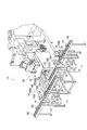
- FIG. 2 is a perspective view showing a surface treatment processing apparatus used in the surface treatment processing method according to the first embodiment.
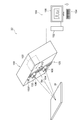
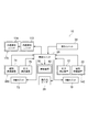
- FIG. 3A is a schematic diagram showing a part of the control system of the surface treatment apparatus of FIG.
- FIG. 3 (B) is a schematic view showing a simplified main part of the shot peening apparatus.
- FIG. 4A is a circuit configuration diagram of the magnetic evaluation apparatus.
- FIG. 4B is a perspective view showing the configuration of the inspection detector in a transparent state.
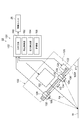
- FIG. 5 is a schematic configuration diagram showing a part of the stress measuring apparatus of FIG.
- FIG. 6 is a schematic configuration diagram showing a part of the stress measuring apparatus of FIG. 2 in a simplified side view.
- FIG. 7 is a schematic diagram for explaining a detection position of the stress measurement apparatus of FIG.
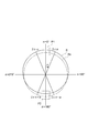
- FIG. 8 is a diagram for explaining a diffraction ring drawn by diffracted X-rays.
- FIG. 9A is a flowchart showing the adjustment process before the residual stress measurement.
- FIG. 9B is a flowchart showing a method of measuring the residual stress on the surface side of the inspection object.
- FIG. 10 is a schematic diagram showing a part of the control system of the surface treatment apparatus according to the modification as a block.
- FIG. 2 shows a perspective view of the surface treatment processing apparatus 10 used in the surface treatment method according to the present embodiment.
- the surface treatment apparatus 10 will be described.
- a metal product or the like can be applied as the processing object W processed by the surface treatment processing apparatus 10 of the present embodiment.
- a gear for an automobile transmission is applied as an example.
- a processing object W before being shot peened (surface processing) by the surface processing apparatus 10 a processing object (product) that has been formed into a product shape by plastic processing and machining is heat-treated as an example. Yes.
- a processing object having a compressive residual stress on the surface side when it is carried into the surface processing apparatus 10 is applied to the processing object W.
- the surface treatment processing device 10 includes a carry-in conveyor 12, a first inspection zone 14, two inspection tables 16 ⁇ / b> A and 16 ⁇ / b> B, a six-axis robot 18, a magnetic evaluation device 20, stress And a measuring device 22.
- the carry-in conveyor 12 conveys the processing object W placed on the carry-in conveyor 12 in a predetermined conveyance direction (see arrow X1).
- a first inspection zone 14 is provided in the transport direction center of the carry-in conveyor 12.
- two inspection tables 16 ⁇ / b> A and 16 ⁇ / b> B are provided so as to straddle the carry-in conveyor 12.
- a six-axis robot 18 is disposed on the side of the carry-in conveyor 12 in the first inspection zone 14.
- the 6-axis robot 18 is a robot that can lift and move the processing object W.
- the six-axis robot 18 can move the processing object W and place it on the inspection tables 16A and 16B (that is, inspection positions). That is, the 6-axis robot 18 moves the processing object W arranged on the carry-in conveyor 12 and arranges it on the inspection table 16A, and the processing object arranged on the inspection table 16A. It is possible to move the object W and arrange it on the inspection table 16B. Further, the 6-axis robot 18 moves the processing object W arranged on the inspection table 16B and arranges it on the carry-in conveyor 12 (downstream side), and is arranged on the inspection table 16B. It is possible to take out the processing target object W outside the surface treatment process line.
- a magnetic evaluation device 20 is provided as an inspection device on one inspection table 16A.
- a stress measuring device 22 is disposed adjacent to the other inspection table 16B as an inspection device.
- the magnetic evaluation device 20 and the stress measurement device 22 constitute a first inspection unit 14E.
- the magnetic evaluation device 20 is arranged on the upstream side in the conveyance direction (see arrow X1) with respect to the stress measurement device 22, but the stress measurement device 22 is in the conveyance direction (arrow with respect to the magnetic evaluation device 20). It may be arranged on the upstream side of X1).
- the magnetic evaluation apparatus 20 inspects the state of the entire surface layer of the processing target portion in the processing target W disposed on the inspection table 16A. For example, the magnetic evaluation device 20 evaluates the presence or absence of unevenness in the processing object W and the state of the metal structure by eddy current. The magnetic evaluation device 20 may output a signal indicating a voltage value as a result of the inspection performed by the magnetic evaluation device 20. The magnetic evaluation apparatus 20 of this embodiment evaluates (determines) whether or not the result of the inspection performed by the magnetic evaluation apparatus 20 is within a predetermined first normal range. The magnetic evaluation apparatus 20 outputs a signal indicating the evaluation result to a control unit 26 (see FIG. 3A) described later.
- the stress measuring device 22 measures the residual stress of the processing object W arranged on the inspection table 16B by using an X-ray diffraction method.
- the stress measuring device 22 of the present embodiment does not measure the overall stress state of the processing object W, and measures the residual stress only at the designated measurement point.
- the stress measuring device 22 outputs a signal indicating a stress value as a measurement result (inspection result) to a control unit 26 (see FIG. 3A) described later.
- the magnetic evaluation apparatus 20 evaluates the homogeneity of the entire processing target surface of the processing object W and also measures the stress. In step 22, a specific residual stress is measured for a part of the processing target range. Details of the magnetic evaluation device 20 and the stress measurement device 22 will be described later.
- FIG. 3A schematically shows a configuration in which a part of the control system of the surface treatment apparatus 10 of FIG.
- the surface treatment processing apparatus 10 further includes a control unit 26.
- the magnetic evaluation device 20, the stress measurement device 22, and the six-axis robot 18 are connected to a control unit 26 (control unit).
- the control unit 26 includes, for example, a storage device and an arithmetic processing device.
- the arithmetic processing unit includes, for example, a CPU, a memory, a storage unit, and a communication interface (I / F) unit, which are connected to each other via a bus.
- a program for arithmetic processing is stored in the storage unit.
- the storage device and the arithmetic processing unit can communicate with each other via a communication interface (I / F) unit.
- the control unit 26 inputs the evaluation result of the magnetic evaluation device 20 from the magnetic evaluation device 20 and inputs the inspection result of the stress measurement device 22 from the stress measurement device 22.
- the evaluation result of the magnetic evaluation device 20 is information indicating whether or not the inspection result of the magnetic evaluation device 20 is within a predetermined first normal magnetic range (first normal range for magnetism). Evaluation of whether or not the test result of the magnetic evaluation device 20 is within the first normal magnetic range is performed by the determination means 96 described later.
- the control unit 26 determines whether or not the inspection result by the stress measurement device 22 is within a predetermined first stress allowable range (first allowable range for stress), and whether the inspection result by the stress measurement device 22 is It is determined (evaluated) whether it is within a predetermined first normal stress range (a first normal range for stress).
- first stress allowable range first allowable range for stress
- second normal range for stress a predetermined first normal stress range
- the “allowable range” is predetermined to be wider than the “normal range” and include the “normal range”. If both the inspection results of the magnetic evaluation device 20 and the stress measurement device 22 are within the first normal range, the control unit 26 evaluates whether or not processing is possible under the standard shot processing conditions (shot peening processing conditions). Make a (judgment).
- control unit 26 has a normal evaluation by the magnetic evaluation device 20 (surface is in a homogeneous state), and the inspection result of the stress measurement device 22 is slightly below or slightly below the standard value (first stress normal range). Evaluation (determination) of “conditional pass” is performed on the processing target W that can be normalized by changing the standard shot processing conditions that exceed. “Conditionally acceptable” means that the processing is possible by changing the shot processing conditions.
- control unit 26 does not correspond to “pass” or “conditional pass” (when the inspection result of the first inspection unit 14E is out of the first allowable range set in advance, that is, this In the embodiment, when the inspection result of the stress measuring device 22 is out of the first stress allowable range), evaluation (determination) of “fail” (in this embodiment, the object to be discarded) is performed.
- control unit 26 determines that the inspection result of the magnetic evaluation device 20 is within a predetermined first normal magnetic range and the inspection result of the stress measurement device 22 is within a predetermined first normal stress range. If it is, it is evaluated as “pass”. The control unit 26 determines that the inspection result of the magnetic evaluation device 20 is within the predetermined first normal magnetic range, and the inspection result of the stress measurement device 22 is out of the predetermined first normal stress range. However, if it is within the predetermined first allowable stress range, it is evaluated as “conditional pass”. The control unit 26 determines that the test result of the magnetic evaluation device 20 is outside the predetermined first normal magnetic range, or the test result of the stress measurement device 22 is outside the predetermined first stress allowable range. If yes, evaluate as “fail”.
- the control unit 26 controls the 6-axis robot 18 so that the processing object W is taken out of the surface treatment process line in the case of “fail”.
- the control unit 26 is other than “fail”, that is, “pass” and “conditionally pass”, the control unit 26 returns the processing object W to the carry-in conveyor 12 (see FIG. 2).
- the robot 18 is controlled.
- the surface treatment apparatus 10 further includes a carry-in / out loader 28 and a shot peening apparatus 30 (shot treatment apparatus).
- a carry-in / out loader 28 On the downstream side of the carry-in side conveyor 12 (on the front side in the drawing), an upstream side of a carry-out side conveyor 66 described later is disposed.
- a cabinet 32 of a shot peening apparatus 30 (shot processing apparatus) serving as a projection unit is disposed on the other side side (the back side in the drawing) on the downstream side of the carry-in conveyor 12.
- the conveyance direction of the carry-out side conveyor 66 (see arrow X2) is set in the same direction as the conveyance direction of the carry-in side conveyor 12 (see arrow X1).
- the cabinet 32 is formed in a box shape.
- An opening 32A for loading / unloading is formed on the side wall of the cabinet 32 on the loading-side conveyor 12 side.
- a loading / unloading loader 28 (loading / unloading device) is provided on the upper side on the downstream side of the loading-side conveyor 12.
- the loading / unloading loader 28 loads the processing object W on the loading-side conveyor 12 from the opening 32A of the cabinet 32 into the cabinet 32, and also transfers the processing object W in the cabinet 32 to the opening 32A of the cabinet 32. Is carried out onto the carry-out conveyor 66.
- the loading / unloading loader 28 includes a pair of rails 28A and a carriage 28B.
- the pair of rails 28 ⁇ / b> A extend in directions orthogonal to the respective conveying directions of the carry-in conveyor 12 and the carry-out conveyor 66.
- the carriage 28B can travel along the pair of rails 28A.
- the carriage 28B is connected to the control unit 26 shown in FIG. Illustration of a mechanism for driving the carriage 28B is omitted.
- the driving of the carriage 28B is controlled by the control unit 26.
- a suspension mechanism (not shown) for suspending the processing object W is provided on the lower surface side of the carriage 28B shown in FIG.
- the lower part that receives and delivers the object to be processed W in the suspension mechanism can be moved up and down.
- FIG. 3B shows a simplified schematic view of the main part of the shot peening apparatus 30.
- the basic configuration of the shot peening apparatus 30 is substantially the same as the configuration disclosed in Japanese Patent Application Laid-Open No. 2012-101304.
- the shot peening apparatus 30 includes a shot processing chamber 34, a product placement unit 36, and an injection device 40.
- a shot processing chamber 34 is formed inside the cabinet 32.
- shot peening processing surface processing in a broad sense
- shot peening processing surface processing in a broad sense
- a projection material a shot of a steel ball or the like
- a nozzle 64 of an injection device (air nozzle type shot peening machine) 40 is provided on a side portion in the cabinet 32.
- the ejection device 40 ejects compressed air containing a projection material from the nozzle 64 to cause the projection material to collide with the processing object W in the shot processing chamber 34.
- the injection device 40 will be briefly described.
- the injection device 40 includes a projection material tank 42, a quantitative supply device 44, and a pressurization tank 46.
- the projecting material tank 42 is connected to the pressurizing tank 46 via a fixed amount supply device 44.
- the fixed amount supply device 44 has a poppet valve 44 ⁇ / b> I provided between the pressurized tank 46.
- the poppet valve 44I is connected to the control unit 26 (see FIG. 3A).
- the pressure tank 46 is provided with a level meter (not shown) that detects the amount of the projection material in the pressure tank 46.
- the level meter is connected to the control unit 26 (see FIG. 3A).
- the control unit 26 see FIG.
- the poppet valve 44I opens the poppet valve 44I of the quantitative supply device 44 when the level meter detects that the amount of the projection material in the pressurized tank 46 is less than a predetermined value.
- the poppet valve 44I is driven by a driving cylinder (not shown).
- the opening and closing of the poppet valve 44I is controlled by the control unit 26 (see FIG. 3A) according to the detection state of the level meter. In a state where the poppet valve 44I is opened, an appropriate amount of the projecting material is sent from the projecting material tank 42 to the pressurizing tank 46 through the quantitative supply device 44.
- An air inlet 46A is formed in the upper part of the pressurized tank 46.
- One end of a connection pipe 48 is connected to the air inlet 46A.
- the other end of the connection pipe 48 is connected to the flow path middle part of the connection pipe 50.
- One end of the connection pipe 50 on the upstream side (right side in the figure) is connected to a compressor 52 (compressed air supply device) for supplying compressed air. That is, the pressurized tank 46 is connected to the compressor 52 via the connection pipes 48 and 50.
- the compressor 52 is connected to the control unit 26 (see FIG. 3A).
- An air flow rate control valve 54 electro-pneumatic proportional valve
- By opening the air flow control valve 54 the compressed air from the compressor 52 is supplied into the pressurized tank 46. Thereby, the inside of the pressurization tank 46 can be pressurized.
- a shot outlet 46B provided with a cut gate 56 is formed in the lower part of the pressurized tank 46.
- One end of a connection pipe 58 is connected to the shot outlet 46B.
- the other end of the connection pipe 58 is connected to the middle part of the flow path of the connection pipe 50.
- a shot flow control valve 60 is provided in the middle of the flow path of the connection pipe 58.
- As the shot flow control valve 60 for example, a magna valve, a mixing valve, or the like is applied.
- a junction part of the connection pipe 50 with the connection pipe 58 is a mixing part 50A.
- an air flow control valve 62 (electro-pneumatic proportional) is provided on the upstream side of the flow path from the mixing section 50A (right side in the figure) and on the downstream side of the flow path from the connection part to the connection pipe 48 (left side in the figure). Valve).
- the cut gate 56 and the shot flow control valve 60 are opened and the air flow control valve 62 is opened while the inside of the pressurization tank 46 is pressurized, the projection material supplied from the pressurization tank 46 is opened.
- the compressed air supplied from the compressor 52 is mixed in the mixing unit 50A and flows to the downstream side (left side in the drawing) of the connection pipe 50.
- a nozzle 64 for injection (for shot peening) is connected to the end of the connection pipe 50 on the downstream side of the flow path. Thereby, the projection material that has flowed to the mixing unit 50A is jetted from the tip of the nozzle 64 while being mixed with the compressed air.
- the air flow control valves 54 and 62, the cut gate 56, and the shot flow control valve 60 are connected to the control unit 26 shown in FIG.
- the surface treatment apparatus 10 further includes an operation unit 24 connected to the control unit 26.
- the operation unit 24 can input a reference value (standard setting reference value) of shot processing conditions when the processing object W (see FIG. 2) is shot peened.
- the operation unit 24 outputs a signal corresponding to the input operation to the control unit 26.
- the control unit 26 Based on the signal output from the operation unit 24 and the inspection result signal output from the magnetic evaluation device 20 and the stress measurement device 22, the control unit 26, the compressor 52, the air shown in FIG.
- the flow control valves 54 and 62, the cut gate 56, the shot flow control valve 60, and the like are controlled.
- control unit 26 shown in FIG. 3A is configured to perform shot processing conditions by the injection device 40, more specifically, a discharge amount (flow rate) per unit time of the projection material, an injection pressure when injecting the projection material, Controls the timing of injection or processing time.
- the control unit 26 when the control unit 26 performs evaluation (determination) that is not “fail” described above, the control unit 26 sets the first shot processing condition when projecting the projection material to the processing target W to be inspected. It is set according to the inspection result of the inspection unit 14E. Specifically, the control unit 26 sets a standard shot processing condition (reference value) as a shot processing condition for the inspection target processing object W for which “pass” is determined. The control unit 26 sets a shot processing condition obtained by correcting the standard shot processing condition (reference value) for the processing target W to be inspected that has been determined to be “pass with condition”.
- control unit 26 controls the injection device 40 so as to inject (project) the projection material under the standard shot processing conditions to the inspection target processing object W that has been determined to be “pass”.
- the control unit 26 injects (projects) the projection material under the shot processing condition in which the standard shot processing condition is corrected with respect to the inspection target processing object W that has been determined as “conditionally passed”. 40 is controlled.
- the processing object W whose inspection result of the stress measuring device 22 is slightly less than the standard value (first stress normal range) among the processing objects W to be inspected that have been judged as “conditionally acceptable”.
- the projection material is injected under shot processing conditions in which the standard shot processing conditions are corrected so that the injection pressure (projection pressure) becomes high.
- the inspection result of the stress measuring device 22 is slightly higher than the standard value (first stress normal range).
- the projection material is injected under shot processing conditions in which standard shot processing conditions are modified so that the injection pressure (projection pressure) is low.
- the injection pressure in the case of injecting a projection material is the input value (the opening degree of the air flow control valves 54 and 62) of the air flow control valves 54 and 62 which are electropneumatic proportional valves shown in FIG. It can be increased or decreased by controlling.
- the product placement unit 36 has a so-called multi-table structure as an example in the present embodiment. That is, a revolution table 36A is arranged on the product placement section 36, and a plurality of revolution tables 36B are arranged on the revolution table 36A at positions on concentric circles of the revolution table 36A.
- the revolution table 36A includes a rotation shaft 35X in the vertical direction of the apparatus.
- the revolution table 36A can rotate (revolve) around the rotation axis 35X.
- the revolution table 36A is arranged at a position including an injection range in which the projection material is injected by the injection device 40 and a non-injection range other than the injection range.
- the diameter of the rotation table 36B is shorter than the diameter of the revolution table 36A.
- the rotation table 36B includes a rotation shaft 35Z parallel to the rotation shaft 35X of the revolution table 36A.
- the rotation table 36B can rotate (rotate) about the rotation axis 35Z.
- the processing object W is arranged on the rotation table 36B.
- a pressing mechanism (not shown) is provided above the injection range in the revolution table 36A.
- the pressing portion of the pressing mechanism can rotate together with the processing object W by pressing the processing object W on the rotation table 36B from above.
- a revolution driving mechanism (not shown) for rotating (revolving) the revolution table 36A and a rotation driving mechanism (not shown) for rotating (spinning) the rotation table 36B are respectively provided in the control unit 26 (see FIG. 3A). It is connected.
- the operations of the revolution drive mechanism and the rotation drive mechanism are controlled by the control unit 26 (see FIG. 3A). By controlling these, the projection position relative to the processing object W, which is one of the shot processing conditions, is controlled.
- the surface treatment processing apparatus 10 includes a carry-out conveyor 66, a second inspection zone 68, two inspection tables 70A and 70B, a six-axis robot 72, a magnetic evaluation apparatus 74, a stress And a measuring device 76.
- the carry-out side conveyor 66 conveys the processing object W placed on the carry-out side conveyor 66 in a predetermined conveyance direction (see arrow X2).
- the carrying direction of the carry-out conveyor 66 is set in the same direction as the carrying direction of the carry-in conveyor 12 (see arrow X1).
- a second inspection zone 68 is provided in the transport direction center of the carry-out conveyor 66. In the second inspection zone 68, two inspection tables 70A and 70B are provided so as to straddle the carry-out conveyor 66.
- a six-axis robot 72 is disposed on the side of the carry-out conveyor 66 in the second inspection zone 68.
- the 6-axis robot 72 is a robot that can lift and move the processing object W.
- the six-axis robot 72 can move the processing object W and place it on the inspection tables 70A and 70B (that is, inspection positions). That is, the 6-axis robot 72 moves the processing object W arranged on the carry-out side conveyor 66 and arranges it on the inspection table 70A, and the processing object arranged on the inspection table 70A.
- the object W can be moved and placed on the inspection table 70B. Further, the 6-axis robot 72 moves the processing object W arranged on the inspection table 70B and arranges it on the carry-out conveyor 66 (downstream side), and is arranged on the inspection table 70B.
- the object to be processed W can be taken out of the surface treatment process line.
- a magnetic evaluation device 74 is provided as an inspection device on one inspection table 70A.
- a stress measuring device 76 is disposed adjacent to the other inspection table 70B as an inspection device.
- the magnetic evaluation device 74 and the stress measurement device 76 constitute a second inspection unit 68E.
- the magnetic evaluation device 74 is arranged on the upstream side in the transport direction (see arrow X2) with respect to the stress measurement device 76, but the stress measurement device 76 is in the transport direction (arrow with respect to the magnetic evaluation device 74). It may be arranged on the upstream side of X2).
- the magnetic evaluation device 74 inspects the state of the entire surface layer of the processing target portion in the processing target W disposed on the inspection table 70A.
- the magnetic evaluation device 74 performs, for example, an evaluation by eddy current on the presence or absence of unevenness in the processing target W and the state of the metal structure.
- the magnetic evaluation device 74 may output a signal indicating a voltage value as a result of the inspection performed by the magnetic evaluation device 74.
- the magnetic evaluation device 74 of the present embodiment determines whether or not the result of the inspection performed by the magnetic evaluation device 74 is within a predetermined second normal magnetic range (second normal range for magnetism). Evaluate (determine).
- the magnetic evaluation device 74 outputs a signal indicating the evaluation result to the control unit 26 (see FIG. 3A).
- the second normal magnetic range may be the same as or different from the first normal magnetic range.
- the stress measuring device 76 measures the residual stress of the processing object W arranged on the inspection table 70B using the X-ray diffraction method.
- the stress measurement device 76 of this embodiment does not measure the overall stress state of the processing object W, but measures the residual stress only at the designated measurement point.
- the stress measuring device 76 outputs a signal indicating a stress value as a measurement result (inspection result) to the control unit 26 (see FIG. 3A).
- the magnetic evaluation device 74 in the second inspection zone 68 has the same configuration as the magnetic evaluation device 20 in the first inspection zone 14.
- the stress measurement device 76 in the second inspection zone 68 has the same configuration as the stress measurement device 22 in the first inspection zone 14.
- the magnetic evaluation device 74, the stress measurement device 76, and the six-axis robot 72 are connected to the control unit 26.
- the control unit 26 inputs the evaluation result of the magnetic evaluation device 74 from the magnetic evaluation device 74 and inputs the inspection result of the stress measurement device 76 from the stress measurement device 76.
- the evaluation result of the magnetic evaluation device 74 is information indicating whether or not the inspection result of the magnetic evaluation device 74 is within a predetermined second normal magnetic range (second normal range for magnetism). Evaluation of whether or not the inspection result of the magnetic evaluation device 74 is within the second normal magnetic range is performed by the determination means 96 described later.
- the control unit 26 determines (evaluates) whether or not the inspection result by the stress measuring device 76 is within a predetermined second normal stress range (second normal range for stress). Note that the second normal stress range may be the same as or different from the first normal stress range. If both the inspection results of the magnetic evaluation device 74 and the stress measurement device 76 are within the second normal range (the inspection result of the second inspection unit 68E is within a predetermined second normal range), the control unit 26 Evaluate (determine) it as “pass”. In other cases, the control unit 26 evaluates (determines) “fail” (in this embodiment, the object to be discarded).
- control unit 26 determines that the inspection result of the magnetic evaluation device 74 is within the predetermined second normal magnetic range and the inspection result of the stress measurement device 76 is the predetermined second normal stress range. If it is within, evaluate as “pass”. The control unit 26 determines that the test result of the magnetic evaluation device 74 is outside the predetermined second normal magnetic range, or the test result of the stress measurement device 76 is out of the predetermined second normal stress range. If it is, it is evaluated as “fail”.
- the control unit 26 controls the 6-axis robot 72 so that the processing object W is returned to the carry-out conveyor 66 (see FIG. 2) when “pass”. In the case of “fail”, the control unit 26 controls the 6-axis robot 72 so that the processing target W is taken out of the surface treatment process line. The processing object W returned to the carry-out side conveyor 66 (see FIG. 2) is flowed to the next process.
- control unit 26 stores the inspection results of the magnetic evaluation device 74 and the stress measurement device 76 in the storage device.
- the control unit 26 can store the second inspection unit 68E (for example, for several tens of days (or for several days) or several weeks (for example, 20 days in the present embodiment) stored in the storage device (see FIG. 2).
- an average value for every day is calculated by the arithmetic processing unit.
- the average value is also simply referred to as “stress average value”.
- the control unit 26 further calculates the difference between the stress average value and the stress standard median value (median value of the second normal stress range) as a deviation amount in the arithmetic processing unit.
- the control unit 26 calculates the slope and intercept of the linear expression indicating the increasing / decreasing tendency (trending change) of the divergence amount from the day (horizontal axis) and the daily divergence amount (vertical axis). Calculated by The control unit 26 determines whether or not the test result of the stress measuring device 76 tends to deviate from the second normal stress range (second normal range for stress) as a medium to long-term trend.
- the control unit 26 calculates a date (“time” in a broad sense) when the stress average value is predicted to be out of the preset second normal stress range (second normal range for stress).
- the control unit 26 then inspects the second inspection unit 68E (stress measurement device 76) at a predetermined timing, which will be described later, based on the tendency of the inspection results of the second inspection unit 68E (stress measurement device 76) to change over time.
- the reference value (standard setting reference value) of the shot processing condition is reset so as to suppress the rate at which the result is out of the second normal stress range.
- the second normal stress range may be the same as or different from the first normal stress range.
- FIG. 4A shows a circuit configuration of the magnetic evaluation apparatus 20 (surface characteristic inspection apparatus).
- FIG. 4B shows the configuration of the inspection detector 86 of the magnetic evaluation apparatus 20 in a perspective view in a transparent state.
- the magnetic evaluation device 20 and the magnetic evaluation device 74 shown in FIG. 2 have the same device configuration, and therefore, the magnetic evaluation device in FIG.
- the magnetic evaluation device 20 includes an AC power supply 78, an AC bridge circuit 80, and an evaluation device 90.
- the AC power supply 78 can supply AC power having a variable frequency to the AC bridge circuit 80.
- the AC bridge circuit 80 includes a variable resistor 82 and a test detection in which a coil is arranged so as to excite eddy currents in a processing target W (hereinafter referred to as “subject W” as appropriate) to be a test subject (test target). And a reference detector 84 for detecting a reference state that is a reference for comparison with the output from the inspection detector 86.
- the variable resistor 82 can distribute the resistor RA between the resistor R1 and the resistor R2 with a distribution ratio ⁇ . The distribution ratio ⁇ is variable.
- the resistors R1 and R2 form a bridge circuit together with the reference detector 84 and the inspection detector 86.
- points A and B are connected to the AC power supply 78 of the magnetic evaluation device 20, and points C and D are connected to the amplifier 91.
- Point A is a point that distributes resistance R1 and resistance R2.
- Point B is located between the reference detector 84 and the inspection detector 86.
- Point C is located between resistor R 1 and reference detector 84.
- Point D is located between resistor R2 and test detector 86.
- the reference detector 84 and the inspection detector 86 are grounded to reduce noise.
- the variable resistor 82 and the reference detector 84 are disposed on the circuit board 88 as an example.
- the evaluation device 90 includes an amplifier 91, an absolute value circuit 92, a low-pass filter (LPF) 93, a phase comparator 94, a frequency adjuster 95, a determination unit 96, a display unit 97, and a temperature measurement unit 98. It is equipped with.
- the amplifier 91 amplifies the voltage signal output from the AC bridge circuit 80.
- the absolute value circuit 92 performs full wave rectification.
- the LPF 93 performs direct current conversion.
- the phase comparator 94 compares the phase of the AC voltage supplied from the AC power supply 78 with the voltage output from the amplifier 91.
- the frequency adjuster 95 adjusts the frequency of the AC voltage supplied from the AC power supply 78.
- the determination means 96 performs non-equilibrium adjustment that optimizes the distribution between the resistors R1 and R2. Further, the judging means 96 inputs the output from the LPF 93 as the inspection result of the magnetic evaluation devices 20 and 74. The determination means 96 determines the quality of the surface state of the processing object W based on the inspection result. Specifically, the determination unit 96 evaluates (determines) whether or not the inspection result is within a predetermined first normal magnetic range or a second normal magnetic range. If the surface state of the processing object W is homogeneous, the inspection results of the magnetic evaluation devices 20 and 74 are within the first normal magnetic range or the second normal magnetic range. The display unit 97 displays and warns the evaluation result by the determination unit 96. The temperature measuring means 98 detects the temperature at the evaluation position.
- the amplifier 91 is connected to point C and point D. The potential difference between the point C and the point D is input to the amplifier 91.
- the output of the amplifier 91 is connected to the absolute value circuit 92.
- the output of the absolute value circuit 92 is connected to the LPF 93.
- the output of the LPF 93 is connected to the judging means 96.
- the phase comparator 94 is connected to the AC power supply 78, the amplifier 91, and the determination unit 96.
- the frequency adjuster 95 is connected to the AC power supply 78 and the amplifier 91. Further, the judgment means 96 can change the position of the point A of the AC bridge circuit 80, that is, the distribution ratio ⁇ of the resistors R1 and R2 by outputting a control signal.
- the temperature measuring means 98 is composed of a non-contact type infrared sensor, a thermocouple, or the like, and outputs a temperature signal of the surface of the subject W to the judging means 96.
- the determining unit 96 determines whether the surface treatment state of the subject W is good or not when the temperature of the subject W detected by the temperature measuring unit 98 is within a predetermined range. When the temperature detected by the temperature measuring unit 98 is outside the predetermined range, the determining unit 96 does not determine whether the surface treatment state of the subject (processing object) W is acceptable.
- the inspection detector 86 and the reference detector 84 have the same configuration.
- a detector formed by winding a coil around the outer periphery of a core that can be inserted through the evaluation unit of the subject W is used as the inspection detector 86 and the reference detector 84.
- This detector can excite an eddy current in the subject W by causing the coil to face and face the surface of the subject W. That is, this coil is wound so as to surround the surface property inspection region of the subject W and faces the surface property inspection region of the subject W.
- surrounding the surface property inspection region of the subject W includes energizing the surface property inspection region by enclosing at least a part of the surface property inspection region (enclosing the surface property inspection region). I mean.
- the inspection detector 86 includes a core 86A and a coil 86B.
- the core 86A has a cylindrical shape and is disposed so as to cover the subject W (schematically illustrated as a cylindrical body in the drawing).
- the coil 86B is made of enameled copper wire wound around the outer peripheral surface of the core 86A.
- a cylindrical magnetic shield 86C is provided so as to surround the core 86A around which the coil 86B is wound.
- the core 86A is formed of a nonmagnetic material, for example, a resin. Note that the shape of the core 86A may not be a cylindrical shape as long as the subject W can be disposed inside. Further, the inspection detector 86 may not include the core 86A as long as the coil 86B can maintain the shape.
- the inspection detector 86 is arranged so that the coil 86B surrounds the inspection target surface (surface characteristic inspection region) of the subject W and the coil 86B faces the inspection target surface of the subject W.
- AC power having a predetermined frequency is supplied to the coil 86B by the AC power supply 78 (see FIG. 4A)
- an AC magnetic field is generated.
- an eddy current flowing in the direction intersecting the AC magnetic field is excited on the surface of the subject W.
- the eddy current changes according to the electromagnetic characteristics of the residual stress layer.
- the phase and amplitude (impedance) of the output waveform (voltage waveform) output from the amplifier 91 change according to the characteristics (surface treatment state) of the residual stress layer.
- the change in the output waveform can detect and inspect the electromagnetic characteristics of the surface treatment layer.
- the evaluation apparatus 90 shown in FIG. 4A evaluates the surface characteristics of the subject W based on the output signal from the AC bridge circuit 80.
- the test detector 86 detects the electromagnetic characteristics of the subject W
- the reference detector 84 detects the reference state. Is in a state.
- the judging means 96 of the evaluation device 90 is connected to the control unit 26.
- the determination unit 96 outputs a signal corresponding to the evaluation result to the control unit 26.
- the determining unit 96 outputs a signal indicating that “inspection is impossible” to the control unit 26. Thereby, the determination means 96 notifies the control unit 26 that the determination result by the inspection could not be obtained.
- the judging means 96 outputs a signal indicating that “inspection is impossible” to the display means 97.
- the display means 97 inputs this signal, and displays and warns that the evaluation result by the judging means 96 is “inspection impossible”.
- an operator may check the magnetic evaluation devices 20 and 74 and improve the operating environment as necessary, and then operate the magnetic evaluation devices 20 and 74 again. Further, for example, the worker may invalidate the inspection result by the evaluation device 90 and operate the magnetic evaluation devices 20 and 74 again. Thereby, the surface characteristics of the subject W can be evaluated again.
- the test detector 86 is arranged on the subject W or the test detector so that an eddy current is excited in the subject W in a state where AC power is supplied from the AC power supply 78 to the AC bridge circuit 80.
- a subject W is placed on 86 (placement step).
- the test detector 86 is arranged so as to surround the subject W arranged first, or the subject W is inserted into the test detector 86 arranged first.
- the evaluation device 90 evaluates the surface characteristics of the subject W based on the output signal output from the AC bridge circuit 80 (evaluation process). Then, the evaluated result is output from the evaluation device 90 to the control unit 26.
- magnetic evaluation by eddy current for example, magnetic evaluation is performed by applying an apparatus disclosed in JP 2013-529286A, JP 2015-525336A, or International Publication No. 2015/107725. It is possible.
- FIG. 5 shows a schematic perspective view of a part of the stress measuring device 22.
- a part of the stress measuring device 22 is shown in a simplified manner in a side view.
- the stress measurement device 22 includes a device main body 100 and a control device 150.
- the apparatus main body 100 is a box-shaped housing.
- an X-ray generation source 102 is accommodated inside the apparatus main body 100.
- the X-ray generation source 102 is an apparatus that includes an X-ray tube and generates X-rays having a predetermined wavelength.
- the X-ray generation source 102 is fixed to the apparatus main body 100.
- X-rays having an appropriate wavelength are used in accordance with the processing object W to be inspected (hereinafter, appropriately abbreviated as “inspection object W”).
- An X-ray irradiation window (not shown) is formed on the front surface 100F of the apparatus main body 100.
- X-rays generated by the X-ray generation source 102 are irradiated onto the inspection object W through the window. 5 and 6, the X-ray path from the X-ray generation source 102 to the inspection object W and the irradiation direction (incident direction) are indicated by a line Xa with an arrow.
- the apparatus main body 100 includes a first detection element 106 and a second detection element 108.
- the first detection element 106 and the second detection element 108 are disposed on the front surface 100F side of the apparatus main body 100.
- the first detection element 106 and the second detection element 108 detect the intensity of the diffracted X-ray of the inspection object W, respectively.
- the first detection element 106 is a zero-dimensional X-ray intensity measurement element.
- the zero dimension means that the X-ray intensity is measured at the element arrangement position. That is, the first detection element 106 is different from a one-dimensional line sensor in which a plurality of elements are arranged along a straight line and a two-dimensional imaging plate in which a plurality of elements are arranged in a plane.
- the second detection element 108 is also a zero-dimensional X-ray intensity measurement element.
- a scintillation counter is used as the first detection element 106 and the second detection element 108.
- the apparatus main body 100 includes a moving mechanism 120 that moves the first detection element 106 and the second detection element 108 along a direction orthogonal to the X-ray incident direction (see the arrow X3 direction). As shown in FIG. 6, the moving mechanism 120 has an electric motor 122 for driving displacement and a ball screw mechanism 124.
- the electric motor 122 is fixed to the apparatus main body 100.
- the ball screw mechanism 124 includes a linear screw 126 extending along a direction orthogonal to the X-ray incident direction (see the arrow X3 direction), a first nut 128 and a second nut 130 screwed into the screw 126, have.
- the screw 126 is supported so as to be rotatable around its axis.
- the electric motor 122 is driven, the screw 126 is rotated about its own axis by transmitting a driving force via a driving force transmission mechanism (not shown).
- the screw 126 is disposed at a position offset laterally with respect to the incident X-ray from the X-ray generation source 102 (in a direction perpendicular to the paper surface of FIG. 6).
- a first slider 132 is fixed to the first nut 128.
- a second slider 134 is fixed to the second nut 130.
- the first slider 132 and the second slider 134 are supported by a pair of rails 136 (see FIG. 5) so as to be slidable in the extending direction.
- the pair of rails 136 is provided on the front surface 100F of the apparatus main body 100 and extends in a direction parallel to the screw 126 (a direction orthogonal to the X-ray incident direction). In FIG. 5, the pair of rails 136 are schematically shown, but a known pair of guide rails can be applied to the pair of rails 136.
- the first detection element 106 is fixed to the first slider 132.
- the second detection element 108 is fixed to the second slider 134.
- the first nut 128 and the first slider 132 and the second nut 130 and the second slider 134 move relative to the screw 126 in the axial direction thereof.
- the first detection element 106 and the second detection element 108 are respectively moved in a direction perpendicular to the incident direction of the X-ray (refer to the arrow X3 direction).
- the first detection element 106 and the second detection element 108 can change the detection position of the X-ray intensity on a straight line by the moving mechanism 120.
- the first detection element 106 detects the intensity of the diffracted X-ray of the inspection object W at the first detection position.
- the second detection element 108 detects the intensity of the diffracted X-ray of the inspection object W at a second detection position different from the first detection position.
- the first detection position and the second detection position can be changed according to the material and focal length of the inspection object W, for example.
- the first detection element 106 and the second detection element 108 move in synchronization with the same preset distance.
- the preset distance is a distance within a range where a necessary diffraction intensity distribution can be obtained.
- the moving mechanism 120 is connected to the control device 150 shown in FIG.
- the control device 150 is configured by a general-purpose computer including a CPU, a ROM, a RAM, an HDD, and the like, for example.
- the control device 150 includes a processing device 152, an input device 154 (for example, a keyboard and a mouse), and an output device 156 (for example, a display).
- the processing device 152 includes an input / output unit 160, a movement control unit 162, a stress calculation unit 164, and a storage unit 166.
- the input / output unit 160 is a communication device such as a network card and an input / output device such as a graphic card.
- the input / output unit 160 is communicably connected to the electric motor 122.
- the input / output unit 160 is connected to the input device 154 and the output device 156 shown in FIG. Further, the input / output unit 160 shown in FIG. 6 is connected to the X-ray generation source 102, the first detection element 106, and the second detection element 108.
- the movement control unit 162 and the stress calculation unit 164 described below exchange information with each component via the input / output unit 160.
- the movement control unit 162 controls the detection positions of the first detection element 106 and the second detection element 108 by driving the movement mechanism 120 (by controlling the driving of the movement mechanism 120).
- the movement control unit 162 acquires in advance the peak appearance angle determined based on the material constituting the inspection object W, and each detection position of the first detection element 106 and the second detection element 108 so as to include the peak appearance angle.
- the peak appearance position determined based on the material constituting the inspection object W is stored in the storage unit 166.
- the stress calculation unit 164 also determines the residual stress of the inspection target W based on the intensity peaks of the diffracted X-rays detected by the movement mechanism 120 moving the first detection element 106 and the second detection element 108, respectively. Is calculated.
- calculation of the residual stress will be described in detail.
- FIG. 7 is a schematic diagram for explaining the detection position of the stress measurement device 22 according to the present embodiment.
- the incident X-rays X IN the inspection object W is irradiated, shows a case where the diffracted X-rays are output at a diffraction angle 2 [Theta].
- the diffraction ring R is drawn by diffracted X-rays on the predetermined plane PL.
- an intensity peak appears at each of the detection position corresponding to 0 ° of the diffraction ring of diffraction X-rays and the detection position corresponding to 180 ° of the diffraction ring of diffraction X-rays.
- a case where the diffraction intensity at a symmetrical point) is acquired is taken as an example.
- FIG. 8 is a schematic diagram for explaining a diffraction ring.
- the movement control unit 162 sets the first detection element 106 (see FIG. 6) to move within a range including the first detection position P1 corresponding to 0 ° of the diffraction ring R.
- the movement control unit 162 sets the second detection element 108 (see FIG.
- the stress calculation unit 164 acquires a diffraction peak based on the X-ray diffraction intensity distribution (relationship between angle and intensity) detected at each of the first detection position P1 and the second detection position P2.
- two intensity peaks that is, an intensity peak corresponding to 0 ° of the diffraction ring R and an intensity peak corresponding to 180 ° of the diffraction ring R can be obtained.
- Diffraction ring R R of the two-dot chain line shown in FIG. 8 is a diffraction ring in the absence of the residual stress in the test object W. In the diffraction ring R in the case where residual stress exists, as compared to the diffraction rings R R when the residual stress is not present, it is shifted center position in accordance with the residual stresses.
- the stress calculator 164 calculates a residual stress value using this difference.
- the stress calculation unit 164 calculates the residual stress value using the cos ⁇ method.
- the residual stress is obtained from the slope of the ⁇ -cos ⁇ diagram.
- the ⁇ -cos ⁇ diagram shows the distortion ( ⁇ ⁇ , ⁇ ⁇ + ⁇ , ⁇ ⁇ , ⁇ ⁇ ) at cos ⁇ ( ⁇ : diffraction center angle) and four locations ( ⁇ , ⁇ + ⁇ , - ⁇ , ⁇ - ⁇ ) on the diffraction ring.
- the relationship with the strain ⁇ expressed using ⁇ ) is shown.
- the X-ray stress measurement multiplier is a constant determined by the Young's modulus, Poisson's ratio, the Bragg angle remainder angle, and the X-ray incident angle, and is stored in advance in the storage unit 166 shown in FIG.
- the stress calculation unit 164 outputs the calculated residual stress value to the control unit 26 via the input / output unit 160.
- the residual stress value calculated by the stress calculation unit 164 may be output to the control unit 26, stored in the storage unit 166, or output to the output device 156 (see FIG. 5).
- FIG. 9A and FIG. 9B are flowcharts showing a residual stress measurement method according to this embodiment.
- FIG. 9A is a flowchart showing the adjustment process before the residual stress measurement.
- an angle adjustment process step S240
- the angle of the incident X-ray with respect to the inspection object W is adjusted.
- the angle of incident X-rays is adjusted by tilting the apparatus main body 100 and adjusting the turning angle ⁇ 1.
- the process of tilting the apparatus main body 100 is performed by a separate apparatus (control unit and actuator) as an example.
- the angle adjustment process (step S240) shown in FIG. 9A the incident angle during measurement is fixed to a predetermined angle (single angle).
- focus adjustment processing (step S242) is executed.
- the focus of the incident X-ray with respect to the inspection object W is adjusted.
- the focus of incident X-rays is adjusted by changing the position of the apparatus main body 100 (see FIG. 6).
- the process for changing the height and position is performed by a separate device (control unit and actuator) as an example.
- FIG. 9A When the flowchart shown in FIG. 9A is completed, the stress measuring device 22 is in a state where the residual stress on the surface side of the inspection object W can be measured.
- FIG. 9B is a flowchart showing a method of measuring the residual stress on the surface side of the inspection object W.
- an X-ray irradiation process (step S250: X-ray irradiation process) is first executed.
- the X-ray generation source 102 irradiates the inspection object W with X-rays.
- measurement processing (step S252: movement control step) is performed during execution of the X-ray irradiation processing (step S250).
- the movement mechanism 120 is driven under the control of the movement control unit 162 to move the first detection element 106 and the second detection element 108 (movement control step), and the first detection element being moved is moved.
- Two X-ray diffraction intensity distributions are obtained based on the detection results of 106 and the second detection element 108.
- the movement of the first detection element 106 and the movement of the second detection element 108 are synchronized.
- the measurement process (step S252) ends, the X-ray irradiation may end.
- a residual stress calculation process (step S254: stress calculation step) is executed.
- the intensity of diffracted X-rays of the inspection object W detected by the first detection element 106 and the second detection element 108 during the execution of the measurement process (step S252: movement control process), respectively.
- the residual stress of the inspection object W is calculated. That is, in the residual stress calculation process (step S254), the stress calculation unit 164 acquires two intensity peaks based on the two X-ray diffraction intensity distributions obtained during the movement. Then, the stress calculation unit 164 calculates the slope of the ⁇ -cos ⁇ diagram and multiplies the X-ray stress measurement multiplier to calculate the residual stress. Finally, the residual stress calculated by the stress calculation unit 164 is output to the control unit 26 (see FIG. 3A) (step S256).
- the residual stress is calculated using the data obtained by moving the first detection element 106 and the second detection element 108, and the calculated residual stress is calculated by the control unit. 26 (see FIG. 3A).
- the first detection element 106 that detects the intensity of the diffracted X-ray at the first detection position P1 (see FIG. 7), and the intensity of the diffracted X-ray is the first. Since the second detection element 108 that detects at the second detection position P2 (see FIG. 7) different from the detection position P1 (see FIG. 7) is provided, two X-ray irradiation (single angle irradiation) Diffracted X-rays can be obtained. Furthermore, each of the first detection element 106 and the second detection element 108 can acquire an X-ray intensity distribution (diffraction peak) for each element by moving along the direction orthogonal to the X-ray incident direction. it can.
- the residual stress of the inspection target W can be calculated by acquiring at least two diffraction peaks. For this reason, it is not necessary to rotate the imaging plate to acquire all data of the diffraction ring. Therefore, the measurement time of the residual stress can be shortened as compared with the conventional residual stress measuring device.
- the stress measuring device 22 does not need to include a mechanism for rotating the imaging plate and a reading mechanism. For this reason, since the stress measuring device 22 is simplified and reduced in weight as compared with the residual stress measuring device having such a mechanism, the stress measuring device 22 can be easily installed and can be incorporated into other machines. Furthermore, in the stress measuring device 22, the manufacturing cost of the device can be reduced compared with the conventional residual stress measuring device by simplifying the device configuration.
- the movement control unit 162 synchronizes the movement of the first detection element 106 and the movement of the second detection element 108 so that the first detection element 106 and the second detection element 108 are individually controlled.
- the measurement time of the residual stress can be shortened.
- the surface treatment processing apparatus 10 includes a magnetic evaluation apparatus 20 shown in FIG. 4 (A) and the like, a stress measurement apparatus 22 shown in FIG. 5 and the like, and a shot peening processing apparatus 30 shown in FIG. 3 (B) and the like. It is out.
- a processing target object W before being carried into the surface processing apparatus 10 shown in FIG. 2 a processing target object (product) formed into a product shape by plastic processing and machining is heat-treated as an example.
- the processing object W carried into the surface treatment apparatus 10 shown in FIG. 2 is placed on the carrying-in conveyor 12 and conveyed.
- the processing object W reaches the first inspection zone 14, it is arranged on the inspection table 16 ⁇ / b> A by the 6-axis robot 18 and inspected by the magnetic evaluation device 20.
- the processing object W is placed on the inspection table 16B by the six-axis robot 18 and inspected by the stress measuring device 22.
- the inspection before the shot process shown in Step S200 of FIG. 1A that is, the first inspection process is executed.
- the state of the surface side of the processing object W before the shot process for projecting the projection material onto the processing object W is nondestructively inspected.
- the inspection result is out of the predetermined first allowable range, it is evaluated as “fail”.
- the magnetic evaluation apparatus 20 performs an inspection to evaluate the magnetic property of the surface of the processing object W by eddy current.
- the specific inspection method is as described above.
- the determination means 96 determines the quality of the surface state based on the inspection result.
- the magnetic evaluation apparatus 20 outputs the inspection result (that is, the evaluation result of the determination unit 96) to the control unit 26 (see FIG. 3A).
- the stress measuring device 22 measures the residual stress on the surface side of the processing object W using the X-ray diffraction method.
- the specific measurement method is as described above.
- the stress measurement device 22 outputs the measurement result to the control unit 26 (see FIG. 3A).
- the control unit 26 evaluates any one of “pass”, “conditional pass”, and “fail” as described above.
- step S202 shown in FIG. 1A the control unit 26 determines whether or not the processing object W is “not rejected”. The process of the control unit 26 proceeds to step S206 if the determination in step S202 is negative, and proceeds to step S204 if the determination in step S202 is affirmed.
- step S206 the control unit 26 controls the 6-axis robot 18 shown in FIG. 2 so that the processing object W is taken out of the surface treatment process line. The processing object W taken out of the line is discarded. That is, the processing object W evaluated as “failed” in the first inspection process is excluded from the shot processing target in advance. Thereby, useless shot peening processing (processing of defective products) can be suppressed in advance.
- step S204 shown in FIG. 1A the control unit 26 determines whether or not the processing object W is “pass”. The process of the control unit 26 proceeds to step S210 if the determination in step S204 is negative, and proceeds to step S208 if the determination in step S204 is affirmed. In step S208 and step S210, a condition setting process is executed. In the condition setting process executed after the first inspection process, the control unit 26 determines the processing object W evaluated as “not rejected” in the first inspection process according to the inspection result in the first inspection process. Set the shot processing conditions.
- step S210 the control unit 26 sets a condition (adjusted condition) obtained by correcting the standard shot processing condition as the shot processing condition of the processing object W determined to be “conditionally passed” (feed forward). ). That is, the shot processing conditions are adjusted individually (for each product) in accordance with the properties of the processing object W (product) before individual shot peening processing. As a result, it is possible to make the processing object W, which can be a defective product when processed under the standard shot processing conditions, as a non-defective product. Thereby, the processing target object W discarded can be reduced. By discarding, productivity can be improved.
- the correction (adjustment) of the shot processing condition of the processing target W determined as “conditionally acceptable” will be described more specifically.
- the correction condition (correction value) of this shot processing condition is calculated as follows. First, in the arithmetic processing unit of the control unit 26, a program including an arithmetic expression stored in advance in the storage unit is read and developed in a memory. Next, the program developed in the memory is executed by the CPU. Thereby, the correction condition is calculated.
- the arithmetic expression is an expression including the reference value of the shot processing condition.
- a program including condition determination may be stored in advance in the arithmetic processing unit of the control unit 26, and the correction condition for the shot processing condition may be determined by executing this program.
- step S208 the control unit 26 sets the standard shot processing condition as it is as the shot processing condition of the processing object W determined as “pass”. By step S210 and step S208, it is possible to perform shot processing according to the processing object W.
- the processing object W determined as “pass” or “conditional pass” is moved from the inspection table 16B onto the carry-in conveyor 12 by the 6-axis robot 18 shown in FIG. Thereafter, the processing object W is carried into the cabinet 32 of the shot peening apparatus 30 by the carry-in / out loader 28 on the downstream side of the carry-in conveyor 12.
- step S212 shown in FIG. 1A that is, a shot processing step is executed.
- a shot processing step that is executed after the condition setting step, a shot process is performed in which the injection device 40 of the shot peening apparatus 30 shown in FIG.
- the shot processing conditions in the shot processing step are set by the control unit 26 in the condition setting step for the processing object W evaluated as “not rejected” by the control unit 26 in the first inspection step.
- shot processing examples include shot peening (processing) and shot blasting (processing).
- shot processes for example, a roughly spherical projection material (shot (including abrasive grains)) of about several tens of ⁇ m to several mm is struck toward the processing object W at high speed. Thereby, the improvement effect of the component surface layer of the process target W is acquired.
- shot peening is used for the purpose of improving the fatigue strength (durability) of parts subjected to repeated loads. Examples of parts that receive repeated loads include automobiles, aircraft, ships, construction machines, processing machines, and steel structures.
- shot peening is not performed correctly, the target surface hardness, hardness distribution, compressive residual stress, and the like are not imparted to the part, and the part may be destroyed at an early stage. Therefore, in order to maintain appropriate processing, it is necessary to perform shot peening processing with sufficient management.
- shot blasting is performed on the same processed products, for example, removal of deposits on the surface such as rust and scale, adjustment of surface shape such as surface roughness, improvement of adhesion such as painting and coating film, or steel structure It is used to ensure an appropriate wear coefficient at the friction joint. Therefore, it is necessary to carry out shot blasting with sufficient management as in shot peening.
- the shot processing in the present embodiment is shot peening.
- the processing object W subjected to the shot processing is carried out from the cabinet 32 of the shot peening apparatus 30 to the upstream side of the carrying-out conveyor 66 by the loading / unloading loader 28 shown in FIG.
- the processing object W is conveyed by the carry-out conveyor 66.
- the processing object W reaches the second inspection zone 68, it is placed on the inspection table 70A by the 6-axis robot 72 and inspected by the magnetic evaluation device 74. Thereafter, the processing object W is placed on the inspection table 70B by the six-axis robot 72 and inspected by the stress measuring device 76.
- the inspection after the shot process shown in step S214 of FIG. 1A that is, the second inspection process is executed.
- the surface side state of the processing object W is inspected nondestructively. If the inspection result is within the predetermined second normal range, it is evaluated as “pass”, and if it is out of the second normal range, it is evaluated as “fail”.
- the magnetic evaluation device 74 performs an inspection to evaluate the magnetic property of the surface of the processing object W by eddy current.
- the specific inspection method is as described above.
- the determination means 96 determines the quality of the surface state based on the inspection result.
- the magnetic evaluation device 74 outputs the inspection result (that is, the evaluation result of the determination means 96) to the control unit 26 (see FIG. 3A).
- the stress measuring device 76 measures the residual stress on the surface side of the processing object W by using the X-ray diffraction method.
- the specific measurement method is as described above.
- the stress measurement device 76 outputs the measurement result to the control unit 26 (see FIG. 3A).
- the control unit 26 evaluates either “pass” or “fail” as described above based on the inspection results of the magnetic evaluation device 74 and the stress measurement device 76.
- step S216 subsequent to step S214 shown in FIG. 1A, the control unit 26 stores the inspection result (measured value) of the stress measuring device 76 in the storage device.
- step S218 following step S216, the control unit 26 determines whether or not the processing object W is “pass”. The process of the control unit 26 proceeds to step S222 if the determination in step S218 is negative, and proceeds to step S220 if the determination in step S218 is affirmed.
- step S222 the control unit 26 controls the 6-axis robot 72 shown in FIG. 2 so that the processing object W is taken out of the surface treatment process line.
- the processing object W taken out of the line is discarded.
- the processing object W determined to be “pass” is moved by the 6-axis robot 72 from the inspection table 70B onto the carry-out conveyor 66. Thereafter, the processing object W is conveyed to the subsequent process by being conveyed by the carry-out side conveyor 66. That is, step S220 shown in FIG.
- the actual processing object W is inspected instead of the test piece in the second inspection step executed after the shot processing step.
- the first inspection process is provided before the shot processing process.
- the processing object W that is not suitable for the shot peening process that is, the shot peening effect cannot be appropriately imparted even if the shot peening process is performed
- this process is executed when the control unit 26 is activated before the daily machining starts.
- step S230 shown in FIG. 1B the control unit 26 determines whether or not it is necessary to reset the reference value of the shot processing condition.
- the stress normal value is preset in a second normal stress range (about stress). Of the second normal range) (the “time” in a broad sense) is predicted by the control unit 26.
- the control unit 26 determines whether or not the execution time of step S230 is after a day that is a predetermined number of days before the predicted date (for example, three days before).
- step S230 Since the method for calculating the day when the stress average value is predicted to deviate from the preset second normal stress range (second normal range for stress) has already been described, description thereof will be omitted.
- the process of the control unit 26 ends when the determination at step S230 shown in FIG. 1B is denied, and when the determination at step S230 is affirmed, the process proceeds to step S232.
- the second inspection process does not evaluate as “pass” based on the tendency of the inspection result by the stress measurement device 76 in the second inspection process over time.
- the control unit 26 resets the reference value of the shot processing condition so as to suppress the ratio (the ratio at which the inspection result of the second inspection unit 68E is outside the second normal range). That is, in the reference value resetting process, the inspection result in the second inspection process is fed back to the reference value of the shot processing condition.
- This reference value resetting process is executed before the day when the stress average value is predicted to be out of the stress specification range (second stress normal range) based on the trend of daily change of the stress average value. It will be.
- control unit 26 resets the reference value of the injection pressure when the projection material is injected as an example of the shot processing conditions.
- the surface treatment processing method and the surface treatment processing apparatus 10 As described above, according to the surface treatment processing method and the surface treatment processing apparatus 10 (see FIG. 2) according to the present embodiment, all the processing objects W that have been shot processed while suppressing wasteful shot processing are processed. The degree can be managed.
- apparatus operation management and product management are known.
- the operation state of the processing apparatus is monitored.
- parameters related to the speed of the projection material specifically, the injection pressure in the air nozzle type shot peening process, the rotation speed of the impeller for projection in the centrifugal type projection apparatus), the flow rate of the projection material, the processing time,
- the rotational speed and rotational state of the processing object W (product) on the rotary table are monitored.
- the process of the shot peening process is guaranteed by the fact that the processing apparatus can be operated in a state where these are within a predetermined specified value.
- the processing object W applied to the present embodiment is a thin product such as a leaf spring and a disc spring.
- the configuration of the surface treatment apparatus applied to the present embodiment is substantially the same as the surface treatment apparatus 10 in the first embodiment shown in FIG. 2, but instead of the magnetic evaluation apparatuses 20 and 74, The configuration differs from that of the surface treatment apparatus 10 in the first embodiment in that a non-contact type laser displacement meter (not shown) is arranged and the stress measuring device 22 of the first inspection unit 14E is not arranged. Other points are substantially the same as those of the first embodiment.
- the laser displacement meter performs nondestructive inspection of the outer dimensions of the processing object W. Thin products are easily deformed by shot peening. For this reason, the laser displacement meter is arranged.
- the laser displacement meter in the first inspection zone 14 constitutes a first inspection unit.
- the laser displacement meter and stress measuring device 76 in the second inspection zone 68 constitutes a second inspection unit.
- the laser displacement meter performs nondestructive inspection (measures initial strain) of the outer dimensions of the processing object W before the shot processing is performed.
- a projection material is projected onto the processing object W.
- the control unit 26 inputs the inspection result of the laser displacement meter, and evaluates “fail” when the inspection result is out of a predetermined first allowable range (first displacement allowable range).
- the control unit 26 targets the processing object W that has been evaluated as not “failed” in the first inspection step, according to the inspection result in the first inspection step. Set the shot processing conditions.
- control unit 26 controls the deformation amount by increasing / decreasing the processing time among the shot processing conditions based on the difference between the target shape and the initial distortion amount.
- the control unit 26 sets the shot processing conditions so that the shape of the processing object W after the shot peening processing approaches the target shape.
- the shot processing step after the first inspection step as in the first embodiment, the shot set in the condition setting step for the processing object W that has been evaluated as not “failed” in the first inspection step.
- a shot process for projecting the projection material onto the processing object W under the processing conditions is performed.
- the laser displacement meter and the stress measuring device 76 perform a nondestructive inspection of the surface side state and the external dimensions of the processing object W.
- the control unit 26 inputs the inspection result, and if it is within a predetermined second normal range (second displacement normal range for displacement, second stress normal range for stress), “pass”. evaluate. That is, in the second inspection step, the strain after processing is measured by the laser displacement meter in order to determine whether or not the shape after shot peening is appropriate.
- the stress measuring device 76 measures the residual stress on the surface side of the processing object W using the X-ray diffraction method.
- the control unit 26 see FIG.
- the control unit 26 evaluates either “pass” or “fail” based on the inspection result of the laser displacement meter and the stress measurement device 76.
- the control unit 26 evaluates as “pass” if the inspection results of the laser displacement meter and the stress measurement device 76 are both within a predetermined second normal range. (Judgment), otherwise it is evaluated (judgment) as “fail” (discard).
- the ratio that is not evaluated as “pass” in the second inspection process based on the tendency of the inspection results in the second inspection process over time (second)
- the reference value of the shot processing condition is reset so as to suppress the ratio at which the inspection result in the inspection process is outside the second normal range. Therefore, the processing object W evaluated as "pass” in the second inspection step can be increased.
- the reference value (standard setting reference value) of the shot processing condition reset in the reference value resetting step is a reference value for the processing time.
- the measurement of the outer diameter dimension of the processing target W may be performed as long as the management dimension for each processing target W can be measured, and a contact-type distance meter such as a micrometer may be applied.
- the state and the outer dimensions of the surface of the processing object W are nondestructively inspected in the first inspection step, and the inspection result is out of a predetermined first allowable range.
- the control unit 26 may evaluate “fail”. That is, in the first inspection step, in addition to the laser displacement meter, for example, a nondestructive inspection by the magnetic evaluation device 20 or the stress measurement device 22 may be performed.
- only the outer dimensions of the processing object W are non-destructively inspected in the second inspection step, and if the inspection result is within a predetermined second normal range, “ It may be evaluated as “pass”.
- the stress measurement device 76 of the second inspection unit 68E is arranged without the stress measurement device 22 of the first inspection unit 14E shown in FIG.
- the stress measurement device 22 of the first inspection unit 14E may be arranged without the stress measurement device 76 of the second inspection unit 68E shown in FIG.
- the shot peening processing apparatus 30 including the injection device 40 is used as the projection unit.
- the projection unit for example, another projection unit such as a shot blast device including a centrifugal projection device that projects a projection material by accelerating it by centrifugal force by rotation of an impeller may be used. Since the centrifugal projection device is a well-known technique, detailed description thereof is omitted.
- a device including a control gauge, an impeller having a plurality of blades, and a drive motor for rotating the impeller corresponds to the centrifugal projection device.
- the control gauge is formed in a cylindrical shape and supplied with a projection material.
- An opening window is formed through the outer peripheral wall of the control gauge as a discharge part for the projection material.
- the plurality of blades are arranged on the outer peripheral side of the control gauge and rotate in the circumferential direction of the control gauge.
- the rotational speed per unit time of the impeller is controlled by controlling the rotational speed per unit time of the drive motor.
- an inspection for measuring the color tone of the surface side of the processing object W to be inspected, and a processing object to be inspected At least one of inspections for measuring the surface roughness of the object W may be included.
- a non-optical system is used.
- a contact laser displacement meter or the like may be applied.
- the color of the processing object W is determined. I can do it.
- a color measurement method using the method shown in JIS Z8722 may be applied.
- the processing target W (target product) is often made of metal, even if an image sensor or gloss meter using a measuring method using the method shown in JIS Z8741 is used for the degree of gloss, Good.
- the inspection apparatus used in the first inspection process and the second inspection process may output the measurement result to an external calculation apparatus and control device in order to record or calculate the measurement result.
- the same inspection item is inspected, but like the first inspection step and the second inspection step in the second embodiment, Different inspection items may be inspected.
- the inspection item corresponding to the processing object W (target product), the previous process, and the shot processing effect (shot peening effect) to be obtained may be inspected.
- a plurality of inspection items may be inspected, or one inspection item may be inspected.
- Various patterns can be applied to the combination of inspection items. In other words, each of the first inspection unit and the second inspection unit may be provided with a single inspection device or a plurality of inspection devices. Various patterns can be applied to the combination of inspection apparatuses.
- control unit 26 a control unit including a PC, a sequencer, a computer such as a microcomputer, or the like can be applied.
- the said computer etc. may be provided in the projection unit (shot peening apparatus 30) side, or may be provided in the 1st test
- the determination means 96 of the magnetic evaluation devices 20 and 74 is within the first normal magnetic range or the second normal magnetic range in which the test results of the magnetic evaluation devices 20 and 74 are predetermined. It is evaluated (determined) whether or not there is, and the evaluation result is output to the control unit 26. Without being limited thereto, the magnetic evaluation devices 20 and 74 output the inspection results (voltage values) of the magnetic evaluation devices 20 and 74 to the control unit 26, and the inspection results are set to the first normal normal range or the first predetermined range. The control unit 26 may evaluate (determine) whether or not it is within the second normal magnetic range.
- the stress measuring devices 22 and 76 may have a judging means.
- the determination means of the stress measuring devices 22 and 76 may evaluate (determine) the inspection results of the stress measuring devices 22 and 76 and output the evaluation results to the control unit 26.
- the control unit 26 evaluates (determines) that processing is possible by changing the “conditional pass”, that is, the shot processing conditions, based on the inspection result of the stress measuring device 22. Based on the inspection result of the evaluation device 20, “conditional pass” may be evaluated (determined). In this case, if the test result of the magnetic evaluation device 20 is within the first normal magnetic range and the test result of the stress measurement device 22 is within the first normal stress range, the control unit 26 is “pass”. And evaluate. Further, the control unit 26 is within the first allowable magnetic range although the test result of the magnetic evaluation device 20 is out of the first normal magnetic range, and the test result of the stress measuring device 22 is within the first normal stress range. If it is within, it is evaluated (determined) as “conditional pass”. The control unit 26 evaluates (determines) “fail” if the test result of the magnetic evaluation device 20 is out of the first allowable magnetic range or the test result of the stress measurement device 22 is out of the first normal magnetic range. .
- control unit 26 may evaluate (determine) “conditional pass” based on both of the inspection results of the magnetic evaluation device 20 and the stress measurement device 22. In this case, if the test result of the magnetic evaluation device 20 is within the first normal magnetic range and the test result of the stress measurement device 22 is within the first normal stress range, the control unit 26 is “pass”. And evaluate. Although the test result of the magnetic evaluation device 20 is within the first normal magnetic range and the test result of the stress measuring device 22 is out of the first normal stress range, the control unit 26 If it is within the allowable range, it is evaluated as “conditional pass”.
- control unit 26 is within the first allowable magnetic range although the test result of the magnetic evaluation device 20 is out of the first normal magnetic range, and the test result of the stress measuring device 22 is the first test result. Even in the normal stress range, it is evaluated as “conditional pass”. Further, the control unit 26 is within the first allowable magnetic range although the test result of the magnetic evaluation device 20 is out of the first normal magnetic range, and the test result of the stress measuring device 22 is the first test result. Even if the stress is out of the normal range but within the first allowable stress range, it is evaluated as “conditional pass”. When the inspection result of the magnetic evaluation device 20 is outside the first allowable magnetic range, or when the inspection result of the stress measuring device 22 is outside the first allowable stress range, the control unit 26 determines “fail”. evaluate.
- the control unit 26 sets a condition (adjusted condition) obtained by correcting the standard shot processing condition as the shot processing condition of the processing object W determined to be “conditionally passed” (feed forward). Thereby, the processing target object W discarded can be reduced.
- a condition adjusted condition obtained by correcting the standard shot processing condition as the shot processing condition of the processing object W determined to be “conditionally passed” (feed forward).
- the processing target object W discarded can be reduced.
- the projection material is injected under the shot processing conditions in which the standard shot processing conditions are corrected so that the injection pressure (projection pressure) becomes high.
- the projection material is injected under shot processing conditions in which standard shot processing conditions are modified so that the injection pressure (projection pressure) is low.
- the processing object W determined to be “conditionally acceptable” in the first inspection step for the processing object W determined to be “conditionally acceptable” in the first inspection step, among the shot processing conditions, for example, in addition to the injection pressure and the processing time when injecting the projection material, per unit time At least one of the ejection amount of the projection material, the projection speed of the projection material, and the projection position relative to the processing object W may be corrected and set.
- the rotational speed per unit time of the impeller may be corrected and set.
- the projection speed of a projection material cannot be changed directly, it can be substituted by the change of the parameter deeply related to a projection speed.
- the relative projection position with respect to the processing target W is the movement range of the air nozzle, the movement amount of the processing target W (processed product), or the rotation table (revolution table, rotation table) on which the processing target W is arranged. It can be changed depending on the amount of rotation.
- the processing object W (product) of “fail” is evaluated by evaluating in two stages of “pass” and “fail” based on the inspection result in the first inspection step. May be equal. That is, the control unit 26 does not distinguish between “conditional pass” and “pass”. The control unit 26 determines “pass” if the inspection result in the first inspection step is within the first allowable range, and “fail” if it is outside the first allowable range. In this case, in the condition setting step, the shot processing condition is set according to the inspection result in the first inspection step, instead of uniformly setting the reference value of the shot processing condition for the “pass” processing object W. Will do.
- the process target W evaluated as "fail” in a 1st inspection process is discarded, the process target W evaluated as "fail” in a 1st inspection process is If it does not flow to the shot processing step, it does not have to be disposed of and may be reused. Further, in the case of reuse, the processing object W evaluated as “failed” may be reused as a processing object for another use, or after being modified in another process, the same surface again. It may be carried into the processing apparatus 10 and processed.
- the process target W evaluated as "fail” in a 1st inspection process is discarded immediately after determination with "fail", and is evaluated as "pass” or "conditional pass". Only the processed object W is passed to the subsequent process.
- the processing object W evaluated as “pass” and the processing object W evaluated as “fail” may be conveyed in a mixed state for convenience of production line configuration. In this case, only the processing object W evaluated as “pass” may be extracted and subjected to shot processing by separating and removing the processing object W evaluated as “fail”.
- the discharge amount per unit time of the projection material, the projection speed of the projection material, the injection pressure when injecting the projection material, and the impeller Includes one or more of the reference values for the number of rotations per unit time of the impeller, the processing time, and the relative projection position relative to the processing object W when projecting with centrifugal force accelerated by the rotation of May be.
- the reference value may be reset to a lower value in addition to the reference value being reset to a higher value.
- the control unit 26 shown in FIG. 3A may calculate an average value every half day instead of an average value every day as the stress average value.
- the control unit determines that the stress average value is within the stress specification range (the second normal range for stress, that is, the second stress, based on the tendency of the stress average value, which is the average value every half day, to change over time. The time when it is predicted to be out of the normal range is calculated.
- the control unit 26 resets the reference value of the shot processing condition before the predicted time.
- the “average value for each predetermined period” may be “an average value for each day” as in the above-described embodiment, or “an average value for every half day” as in the modification of the above-described embodiment. Alternatively, it may be an average value every other predetermined period (for example, an average value every week, etc.).
- the control unit 26 does not tend to change the inspection result by the stress measurement device 76 in the second inspection process with time, but the inspection result by the magnetic evaluation apparatus 74 in the second inspection process.
- the reference value of the shot processing condition so as to suppress the ratio that is not evaluated as “pass” in the second inspection step (the ratio that the inspection result of the second inspection unit 68E is out of the second normal range). May be reset. That is, the inspection result of the magnetic evaluation device 74 may be fed back with respect to the reference value of the shot processing condition. Further, both the inspection results of the magnetic evaluation device 74 and the stress measurement device 76 may be fed back with respect to the reference value of the shot processing condition.
- the stress measurement apparatuses 22 and 76 are provided with the 1st detection element 106 and the 2nd detection element 108 which are shown by FIG. 6 etc., the stress measurement apparatuses 22 and 76 have three or more detection elements. May be provided.
- the moving mechanism 120 shown in FIG. 6 has a single unit for moving the first detection element 106 and the second detection element 108, respectively.
- Electric motor 122 and a single ball screw mechanism 124 that is operated by a single electric motor 122.
- the electric motor and ball screw mechanism corresponding to each of the first detection element 106 and the second detection element 108 are provided. You may have.
- the control device 150 can control the movement of the first detection element 106 and the second detection element 108 by controlling the electric motor corresponding to each of the first detection element 106 and the second detection element 108. it can.
- the control device 150 can control the two electric motors to synchronize the movements of the first detection element 106 and the second detection element 108 or not.
- the process target W inspected by a 1st test process is heat-processed
- inspected by a 1st test process is like the process target etc. which were nitrided, for example. It may be a processing object W that has been subjected to a process that is neither a shot process nor a heat treatment. Further, as a modification of the above-described embodiment, compressive residual stress may be applied to the surface side of the processing target W having tensile residual stress at the stage of the first inspection process by performing shot peening in the shot processing process. .
- the surface treatment apparatus 10 may further include a storage unit 170 as shown in FIG.
- the storage unit 170 stores at least one of the inspection result by the first inspection unit 14E, the inspection result by the second inspection unit 68E, and the shot processing conditions as data acquired by the surface treatment processing apparatus 10.
- the storage unit 170 may store at least one of the inspection result by the first inspection unit 14E and the inspection result by the second inspection unit 68E.
- the storage unit 170 stores, for example, all of the inspection result by the first inspection unit 14E, the inspection result by the second inspection unit 68E, and the shot processing conditions.
- the storage unit 170 has an internal storage unit 172 and an external storage unit 174.
- the internal storage unit 172 is a storage unit dedicated to the surface treatment apparatus 10 and is not shared with other surface treatment apparatuses 10.
- the internal storage unit 172 is a flash memory such as an SD card or an HDD directly connected to the control unit 26, for example.
- the external storage unit 174 is a storage unit shared with other surface treatment apparatuses 10. Note that the external storage unit 174 only needs to have a configuration that can be shared with other surface treatment apparatuses 10, and may not actually be shared with other surface treatment apparatuses 10.
- the external storage unit 174 is, for example, a local (inside a facility such as a factory) or an external (outside a facility such as a factory) connected to the control unit 26 via an intranet or Internet line.
- the external storage unit 174 may be a server in the surface treatment apparatus 10 as long as it has a configuration that can be shared with other surface treatment apparatuses 10.
- the server may be a cloud server.
- the external storage unit 174 can store data acquired by the plurality of surface treatment apparatuses 10, for example.
- the storage unit 170 uses the inspection result in the first inspection process and the second inspection process as the data acquired by the surface treatment processing apparatus 10. At least one of the inspection result and the shot processing condition is stored (storage process). In the storage process, the storage unit 170 may store at least one of the inspection result in the first inspection process and the inspection result in the second inspection process. Such storage unit 170 and the storage process increase the usability of these data. For example, the trend of the operating condition of the surface treatment apparatus 10 or the plurality of surface treatment apparatuses 10 can be analyzed after the fact.
- the data acquired by the surface treatment apparatus 10 is temporarily stored in the internal storage unit 172, for example. Thereafter, the data stored in the internal storage unit 172 is sent to the external storage unit 174 every predetermined period (every shot processing or every day) and stored in the external storage unit 174. Therefore, for example, these data can be temporarily stored in the internal storage unit 172 and then stored in the external storage unit 174 at an arbitrary timing.
- the storage process is performed as step S217 instead of the process of step S216 in FIG. It may be broken.
- the inspection result by the first inspection unit 14E may be stored in the internal storage unit 172 in the first inspection process in step S200, and the inspection result by the second inspection unit 68E is stored in the second inspection process in step S214.
- the shot processing conditions may be stored in the storage unit 172, and the shot processing conditions may be stored in the internal storage unit 172 in the condition setting process in step S208 or step S210.
- the data may be stored in the server through a transmission step of transmitting the data to the server. That is, the surface treatment processing method may include a first transmission step of transmitting the inspection result by the first inspection unit 14E to the server, or may include a second transmission step of transmitting the inspection result by the second inspection unit 68E to the server. Alternatively, a shot processing condition transmission step of transmitting the shot processing conditions to the server may be included.
- the control unit 26 may set shot processing conditions according to information input from the server. Further, in the reference value setting step, the control unit 26 may set the reference value according to information input from the server. Specifically, by executing a program read from the storage unit in the arithmetic processing unit of the control unit 26, the correction condition of the shot processing condition or the reference value of the shot processing condition is calculated.
- the control unit 26 can send and receive (input / output) information to and from the server through the communication interface unit.
- the information input from the server may be, for example, a trend of the operating status of the surface treatment apparatus 10 obtained by data analysis, or a plurality of surface treatment apparatuses 10. According to such information, the shot processing conditions can be optimized.
- marking for product identification with a laser marker is performed on the processing object W before the first inspection process or after the first inspection process and before the shot processing process (You may make a stamp.
- the control unit 26 stores the identification information corresponding to the marking, the inspection result information in the first inspection process, and the inspection result information in the second inspection process in an external storage device (storage unit). It may be memorized. Accordingly, it is possible to provide a traceability system that can confirm history information of a finished product using a reader for reading marks.
- the storage unit 170 may store these pieces of information (storage process).
- a method for giving identification information such as a serial number (back number) to the processing object W is not particularly limited as long as the processing object W can be specified by the identification information.
- identification information such as a serial number (back number)
- back number a serial number
- Examples of data stored in the external storage device or storage unit 170 include operation data of the surface treatment apparatus 10 in addition to the above-described identification information of the processing object W and work information data including the inspection result.
- the workpiece information data may further include, for example, an inspection time, a name (identification information) of the surface treatment processing apparatus 10, or a processing start time.
- the operation data of the surface treatment processing device 10 includes, for example, an injection pressure (air pressure), a processing start time, a discharge amount of a projection material per unit time (shot injection amount), an air flow rate, or a workpiece rotation speed. That is, the operation data of the surface treatment apparatus 10 includes shot processing conditions.
- the operation data of the surface treatment apparatus 10 includes operation data for each air nozzle.
- the storage unit 170 may store these data in separate databases according to the timing of measurement, for example.
- DESCRIPTION OF SYMBOLS 10 Surface treatment processing apparatus, 14E ... 1st test
Landscapes
- Physics & Mathematics (AREA)
- General Physics & Mathematics (AREA)
- Engineering & Computer Science (AREA)
- Health & Medical Sciences (AREA)
- Chemical & Material Sciences (AREA)
- Mechanical Engineering (AREA)
- Toxicology (AREA)
- Pathology (AREA)
- Life Sciences & Earth Sciences (AREA)
- General Health & Medical Sciences (AREA)
- Analytical Chemistry (AREA)
- Immunology (AREA)
- Crystallography & Structural Chemistry (AREA)
- Biochemistry (AREA)
- Manufacturing & Machinery (AREA)
- Quality & Reliability (AREA)
- Automation & Control Theory (AREA)
- General Engineering & Computer Science (AREA)
- Analysing Materials By The Use Of Radiation (AREA)
- Investigating Materials By The Use Of Optical Means Adapted For Particular Applications (AREA)
- Electrical Discharge Machining, Electrochemical Machining, And Combined Machining (AREA)
Abstract
Priority Applications (7)
| Application Number | Priority Date | Filing Date | Title |
|---|---|---|---|
| CN201780029831.3A CN109153109B (zh) | 2016-05-16 | 2017-05-16 | 表面处理加工方法以及表面处理加工装置 |
| BR112018014159A BR112018014159A2 (pt) | 2016-05-16 | 2017-05-16 | método de processamento de tratamento de superfície e dispositivo de processamento de tratamento de superfície |
| JP2018518310A JP6756366B2 (ja) | 2016-05-16 | 2017-05-16 | 表面処理加工方法及び表面処理加工装置 |
| US16/098,164 US11045922B2 (en) | 2016-05-16 | 2017-05-16 | Surface treatment processing method and surface treatment processing device |
| MX2018013681A MX2018013681A (es) | 2016-05-16 | 2017-05-16 | Metodo de proceso de tratamiento superficial y dispositivo de proceso de tratamiento superficial. |
| EP17799383.9A EP3388196B1 (fr) | 2016-05-16 | 2017-05-16 | Procédé et dispositif de traitement pour traiter une surface |
| KR1020187026326A KR102373431B1 (ko) | 2016-05-16 | 2017-05-16 | 표면 처리 가공 방법 및 표면 처리 가공 장치 |
Applications Claiming Priority (2)
| Application Number | Priority Date | Filing Date | Title |
|---|---|---|---|
| JP2016098179 | 2016-05-16 | ||
| JP2016-098179 | 2016-05-16 |
Publications (1)
| Publication Number | Publication Date |
|---|---|
| WO2017199959A1 true WO2017199959A1 (fr) | 2017-11-23 |
Family
ID=60325184
Family Applications (1)
| Application Number | Title | Priority Date | Filing Date |
|---|---|---|---|
| PCT/JP2017/018377 Ceased WO2017199959A1 (fr) | 2016-05-16 | 2017-05-16 | Procédé et dispositif de traitement pour traiter une surface |
Country Status (9)
| Country | Link |
|---|---|
| US (1) | US11045922B2 (fr) |
| EP (1) | EP3388196B1 (fr) |
| JP (1) | JP6756366B2 (fr) |
| KR (1) | KR102373431B1 (fr) |
| CN (1) | CN109153109B (fr) |
| BR (1) | BR112018014159A2 (fr) |
| MX (1) | MX2018013681A (fr) |
| TW (1) | TWI776811B (fr) |
| WO (1) | WO2017199959A1 (fr) |
Cited By (8)
| Publication number | Priority date | Publication date | Assignee | Title |
|---|---|---|---|---|
| JP2019098442A (ja) * | 2017-11-30 | 2019-06-24 | 新東工業株式会社 | ショット装置 |
| WO2019207890A1 (fr) * | 2018-04-27 | 2019-10-31 | 新東工業株式会社 | Dispositif d'inspection de noyau, système d'inspection de noyau et procédé d'inspection de noyau |
| WO2019216383A1 (fr) | 2018-05-09 | 2019-11-14 | 三菱製鋼株式会社 | Procédé de fabrication de ressort et ressort |
| JP2020094874A (ja) * | 2018-12-11 | 2020-06-18 | パルステック工業株式会社 | X線回折測定装置 |
| JP2020128946A (ja) * | 2019-02-12 | 2020-08-27 | パルステック工業株式会社 | X線回折測定装置 |
| EP3587033A4 (fr) * | 2017-05-16 | 2020-12-30 | Sintokogio, Ltd. | Procédé de transformation de traitement de surface et dispositif de transformation de traitement de surface |
| JP2021151669A (ja) * | 2020-03-24 | 2021-09-30 | 日立Astemo株式会社 | 投射材の投射条件決定方法及びコイルばねの製造方法 |
| US20220099586A1 (en) * | 2020-09-25 | 2022-03-31 | Hongfujin Precision Electronics (Zhengzhou) Co., Ltd. | Detection device |
Families Citing this family (8)
| Publication number | Priority date | Publication date | Assignee | Title |
|---|---|---|---|---|
| CN110891735A (zh) * | 2017-09-27 | 2020-03-17 | 新东工业株式会社 | 表面处理装置以及表面处理方法 |
| DE112018005472T5 (de) * | 2017-09-29 | 2020-06-25 | Sintokogio, Ltd. | Zahnradpositioniervorrichtung, Spannungsmesssystem, Zahnradpositionierverfahren und Beanspruchungs-Messverfahren |
| JP2019124481A (ja) * | 2018-01-12 | 2019-07-25 | 株式会社神戸製鋼所 | 残留応力測定方法 |
| JP6984623B2 (ja) * | 2019-02-01 | 2021-12-22 | 新東工業株式会社 | スラリー供給装置、湿式ブラスト加工装置及びスラリー供給方法 |
| US11625844B2 (en) * | 2020-05-11 | 2023-04-11 | The Boeing Company | Rapid effective case depth measurement of a metal component using physical surface conditioning |
| CN114473876B (zh) * | 2022-02-08 | 2023-03-24 | 成都中科翼能科技有限公司 | 一种清除叶片表面残余渗层的方法 |
| CN118635979B (zh) * | 2024-07-15 | 2025-05-06 | 苏州卡茗特自动化设备有限公司 | 一种吊具剥离震荡机及其智能检测系统 |
| CN119973885A (zh) * | 2025-04-09 | 2025-05-13 | 太原科技大学 | 热轧板带残余应力在线调控系统的喷砂装置、喷砂装置的使用方法及热轧板带残余应力在线调控系统 |
Citations (5)
| Publication number | Priority date | Publication date | Assignee | Title |
|---|---|---|---|---|
| JPH05322870A (ja) * | 1992-05-19 | 1993-12-07 | Hitachi Ltd | クロマトグラフ装置 |
| JP2003127065A (ja) * | 2001-10-19 | 2003-05-08 | Nkk Corp | 鋼板の表面形態制御方法及び鋼板 |
| JP2004344924A (ja) * | 2003-05-22 | 2004-12-09 | Fuji Heavy Ind Ltd | 鋳物の溶射前処理方法 |
| JP2011185638A (ja) * | 2010-03-05 | 2011-09-22 | Omron Corp | はんだ印刷状態の分析作業の支援方法およびはんだ印刷検査機 |
| WO2016203672A1 (fr) * | 2015-06-18 | 2016-12-22 | 新東工業株式会社 | Dispositif de mesure de tension résiduelle et procédé de mesure de tension résiduelle |
Family Cites Families (31)
| Publication number | Priority date | Publication date | Assignee | Title |
|---|---|---|---|---|
| US3639760A (en) * | 1969-11-13 | 1972-02-01 | Rigaku Denki Co Ltd | X-ray diffraction apparatus for measuring stress in a specimen |
| DE2308446C3 (de) * | 1973-02-21 | 1975-09-25 | Institut Dr. Friedrich Foerster, Pruefgeraetebau, 7410 Reutlingen | Richtmaschine für langgestrecktes, metallisches Richtgut |
| US4561062A (en) * | 1983-02-18 | 1985-12-24 | Her Majesty The Queen In Right Of Canada, As Represented By The Minister Of Energy, Mines And Resources | Stress measurement by X-ray diffractometry |
| US5125016B1 (en) * | 1983-09-22 | 1998-02-24 | Outokumpu Oy | Procedure and measuring apparatus based on x-ray diffraction for measuring stresses |
| JPH05279816A (ja) | 1992-03-31 | 1993-10-26 | Mazda Motor Corp | 金属製部材のショットピーニング条件設定法 |
| US5414353A (en) * | 1993-05-14 | 1995-05-09 | Ndt Technologies, Inc. | Method and device for nondestructively inspecting elongated objects for structural defects using longitudinally arranged magnet means and sensor means disposed immediately downstream therefrom |
| JP3702496B2 (ja) * | 1995-07-10 | 2005-10-05 | 三菱電機株式会社 | 数値制御装置を用いた加工方法 |
| US6776212B1 (en) * | 2002-06-21 | 2004-08-17 | L&P Property Management Company | Die casting process incorporating computerized pattern recognition techniques |
| JP3733094B2 (ja) * | 2002-08-22 | 2006-01-11 | トヨタ自動車株式会社 | 良否判定装置、良否判定プログラムおよび良否判定方法 |
| JP4574165B2 (ja) * | 2003-12-26 | 2010-11-04 | ルネサスエレクトロニクス株式会社 | ブラスト処理方法 |
| JP4676244B2 (ja) * | 2005-05-13 | 2011-04-27 | 株式会社日立製作所 | X線撮像装置 |
| US7672745B1 (en) * | 2006-03-20 | 2010-03-02 | Tuszynski Steve W | Manufacturing process analysis and optimization system |
| JP2007318036A (ja) * | 2006-05-29 | 2007-12-06 | Toshiba Corp | 半導体製造装置管理システム、半導体製造装置の異常要因抽出方法及びその管理方法 |
| US20080183404A1 (en) * | 2007-01-13 | 2008-07-31 | Arsalan Alan Emami | Monitoring heater condition to predict or detect failure of a heating element |
| US7491319B1 (en) * | 2008-03-17 | 2009-02-17 | Te Hung En Enterprise Co., Ltd. | Inspecting apparatus with eddy current inspection |
| DE102008020108B3 (de) * | 2008-04-22 | 2010-01-14 | Bruker Axs Gmbh | Röntgendiffraktometer zum mechanisch korrelierten Verfahren von Quelle, Detektor und Probenposition |
| JP5321978B2 (ja) | 2009-10-07 | 2013-10-23 | 新東工業株式会社 | 連続式のコンベア式ショットピーニング装置及びショットピーニング方法 |
| US8848871B2 (en) * | 2010-11-04 | 2014-09-30 | Ut-Battelle, Llc | X-ray backscatter imaging of nuclear materials |
| JP2012173128A (ja) * | 2011-02-21 | 2012-09-10 | Fujifilm Corp | 放射線画像検出装置及び放射線撮影装置 |
| TWI530679B (zh) * | 2011-05-10 | 2016-04-21 | 新東工業股份有限公司 | 表面特性檢查裝置及表面特性檢查方法 |
| JP5851813B2 (ja) | 2011-12-05 | 2016-02-03 | 三菱重工業株式会社 | 板状ワークの湾曲保持装置および湾曲保持方法ならびに湾曲成形方法 |
| DE112013003216B4 (de) | 2012-06-27 | 2024-10-31 | Sintokogio, Ltd. | Kugelstrahlverfahren, Kugelstrahlbeurteilungsverfahren, und Kugelstrahlbeurteilungsaufbaustruktur |
| WO2014054140A1 (fr) * | 2012-10-03 | 2014-04-10 | 新日鐵住金株式会社 | Procédé de calcul de déformation et système de laminage |
| US9613728B2 (en) * | 2013-03-15 | 2017-04-04 | Proto Manufacturing Ltd. | X-ray diffraction apparatus and method |
| JP5877505B2 (ja) * | 2013-05-30 | 2016-03-08 | 新東工業株式会社 | 表面特性検査装置、表面特性検査システム及び表面特性検査方法 |
| JP6052713B2 (ja) * | 2014-01-20 | 2016-12-27 | 新東工業株式会社 | 表面特性検査方法 |
| JP6176596B2 (ja) * | 2014-02-21 | 2017-08-09 | 新東工業株式会社 | 表面特性検査選別装置、表面特性検査選別システム及び表面特性検査選別方法 |
| DE102014205999A1 (de) * | 2014-03-31 | 2015-10-01 | Bayerische Motoren Werke Aktiengesellschaft | Bearbeitungsvorrichtung zum Bearbeiten eines gegossenen Gussrohteils und Verfahren zum Herstellen eines Gussbauteils |
| US10604350B1 (en) * | 2014-10-27 | 2020-03-31 | Surface Combustion, Inc. | System for controlling torque-limiting drive charge car |
| JP6310866B2 (ja) * | 2015-01-30 | 2018-04-11 | 株式会社日立ハイテクノロジーズ | プラズマ処理装置及びプラズマ処理方法並びに解析方法 |
| US10715393B1 (en) * | 2019-01-18 | 2020-07-14 | Goldman Sachs & Co. LLC | Capacity management of computing resources based on time series analysis |
-
2017
- 2017-05-16 BR BR112018014159A patent/BR112018014159A2/pt not_active Application Discontinuation
- 2017-05-16 CN CN201780029831.3A patent/CN109153109B/zh active Active
- 2017-05-16 WO PCT/JP2017/018377 patent/WO2017199959A1/fr not_active Ceased
- 2017-05-16 KR KR1020187026326A patent/KR102373431B1/ko active Active
- 2017-05-16 TW TW106116157A patent/TWI776811B/zh active
- 2017-05-16 MX MX2018013681A patent/MX2018013681A/es unknown
- 2017-05-16 US US16/098,164 patent/US11045922B2/en active Active
- 2017-05-16 EP EP17799383.9A patent/EP3388196B1/fr active Active
- 2017-05-16 JP JP2018518310A patent/JP6756366B2/ja active Active
Patent Citations (5)
| Publication number | Priority date | Publication date | Assignee | Title |
|---|---|---|---|---|
| JPH05322870A (ja) * | 1992-05-19 | 1993-12-07 | Hitachi Ltd | クロマトグラフ装置 |
| JP2003127065A (ja) * | 2001-10-19 | 2003-05-08 | Nkk Corp | 鋼板の表面形態制御方法及び鋼板 |
| JP2004344924A (ja) * | 2003-05-22 | 2004-12-09 | Fuji Heavy Ind Ltd | 鋳物の溶射前処理方法 |
| JP2011185638A (ja) * | 2010-03-05 | 2011-09-22 | Omron Corp | はんだ印刷状態の分析作業の支援方法およびはんだ印刷検査機 |
| WO2016203672A1 (fr) * | 2015-06-18 | 2016-12-22 | 新東工業株式会社 | Dispositif de mesure de tension résiduelle et procédé de mesure de tension résiduelle |
Cited By (20)
| Publication number | Priority date | Publication date | Assignee | Title |
|---|---|---|---|---|
| US11389930B2 (en) | 2017-05-16 | 2022-07-19 | Sintokogio, Ltd. | Surface treatment processing method and surface treatment processing device |
| EP3587033A4 (fr) * | 2017-05-16 | 2020-12-30 | Sintokogio, Ltd. | Procédé de transformation de traitement de surface et dispositif de transformation de traitement de surface |
| JP2019098442A (ja) * | 2017-11-30 | 2019-06-24 | 新東工業株式会社 | ショット装置 |
| WO2019207890A1 (fr) * | 2018-04-27 | 2019-10-31 | 新東工業株式会社 | Dispositif d'inspection de noyau, système d'inspection de noyau et procédé d'inspection de noyau |
| JP2019188462A (ja) * | 2018-04-27 | 2019-10-31 | 新東工業株式会社 | 中子検査装置、中子検査システム、及び中子検査方法 |
| US11953425B2 (en) | 2018-04-27 | 2024-04-09 | Sintokogio, Ltd. | Core inspection device, core inspection system, and core inspection method |
| WO2019216383A1 (fr) | 2018-05-09 | 2019-11-14 | 三菱製鋼株式会社 | Procédé de fabrication de ressort et ressort |
| KR20200141491A (ko) | 2018-05-09 | 2020-12-18 | 미쓰비시 세이코 가부시키가이샤 | 스프링의 제조 방법 및 스프링 |
| US11965571B2 (en) | 2018-05-09 | 2024-04-23 | Mitsubishi Steel Mfg. Co., Ltd. | Method for manufacturing spring and spring |
| RU2759059C1 (ru) * | 2018-05-09 | 2021-11-09 | Мицубиси Стил Мфг. Ко., Лтд. | Способ получения пружины и пружина |
| JP2020094874A (ja) * | 2018-12-11 | 2020-06-18 | パルステック工業株式会社 | X線回折測定装置 |
| JP2020128946A (ja) * | 2019-02-12 | 2020-08-27 | パルステック工業株式会社 | X線回折測定装置 |
| CN115135451A (zh) * | 2020-03-24 | 2022-09-30 | 日立安斯泰莫株式会社 | 弹丸的投射条件的确定方法和螺旋弹簧的制造方法 |
| JP7270572B2 (ja) | 2020-03-24 | 2023-05-10 | 日立Astemo株式会社 | 投射材の投射条件決定方法及びコイルばねの製造方法 |
| CN115135451B (zh) * | 2020-03-24 | 2024-01-30 | 日立安斯泰莫株式会社 | 弹丸的投射条件的确定方法和螺旋弹簧的制造方法 |
| WO2021192912A1 (fr) * | 2020-03-24 | 2021-09-30 | 日立Astemo株式会社 | Procédé de détermination de condition de propulsion pour milieu de grenaillage et procédé de fabrication de ressort hélicoïdal |
| JP2021151669A (ja) * | 2020-03-24 | 2021-09-30 | 日立Astemo株式会社 | 投射材の投射条件決定方法及びコイルばねの製造方法 |
| US12097591B2 (en) | 2020-03-24 | 2024-09-24 | Hitachi Astemo, Ltd. | Method for determining propelling condition for shot medium, and method for manufacturing coil spring |
| US20220099586A1 (en) * | 2020-09-25 | 2022-03-31 | Hongfujin Precision Electronics (Zhengzhou) Co., Ltd. | Detection device |
| US11965833B2 (en) * | 2020-09-25 | 2024-04-23 | Hongfujin Precision Electronics (Zhengzhou) Co., Ltd. | Detection device |
Also Published As
| Publication number | Publication date |
|---|---|
| KR102373431B1 (ko) | 2022-03-11 |
| BR112018014159A2 (pt) | 2018-12-11 |
| CN109153109B (zh) | 2020-11-20 |
| KR20190008182A (ko) | 2019-01-23 |
| TW201801856A (zh) | 2018-01-16 |
| EP3388196B1 (fr) | 2024-07-17 |
| US11045922B2 (en) | 2021-06-29 |
| CN109153109A (zh) | 2019-01-04 |
| TWI776811B (zh) | 2022-09-11 |
| EP3388196A4 (fr) | 2019-07-31 |
| MX2018013681A (es) | 2019-05-02 |
| JP6756366B2 (ja) | 2020-09-16 |
| EP3388196A1 (fr) | 2018-10-17 |
| JPWO2017199959A1 (ja) | 2019-03-28 |
| US20190143482A1 (en) | 2019-05-16 |
Similar Documents
| Publication | Publication Date | Title |
|---|---|---|
| JP6756366B2 (ja) | 表面処理加工方法及び表面処理加工装置 | |
| JP6984655B2 (ja) | 表面処理加工方法及び表面処理加工装置 | |
| CN103562712B (zh) | 用于检测在飞机部件或燃气涡轮部件中的裂纹的方法和设备 | |
| US12182479B2 (en) | System and method for in-situ inspection of additive manufacturing materials and builds | |
| TWI645188B (zh) | 表面特性檢查方法及表面特性檢查裝置 | |
| TW201530108A (zh) | 表面特性檢查裝置及表面特性檢查方法 | |
| CN105074450A (zh) | 表面特性检查装置、表面特性检查系统以及表面特性检查方法 | |
| Jermak et al. | Static characteristics of air gauges applied in the roundness assessment | |
| Rümmler et al. | Study of the influence of additive manufacturing applicable surface treatment methods on mechanical part properties for use in aerospace applications: C. Rümmler et al. | |
| Heide et al. | Automated geometry measurement and deep rolling of butt welds | |
| CN107923878B (zh) | 钢材产品的表面特性检查方法和表面特性检查装置 | |
| US11625844B2 (en) | Rapid effective case depth measurement of a metal component using physical surface conditioning | |
| BR112019015928B1 (pt) | Método de processamento de tratamento de superfície | |
| US20200393411A1 (en) | Electromagnetic probe testing of bond coat | |
| Lavoie | A Guide to Industrial Metrologists: How the manufacturing industry can increase productivity with automated quality control | |
| Buschur | Evaluate Materials with Eddy Current | |
| Vora | Variations in the manufacturing of Rockwell test blocks |
Legal Events
| Date | Code | Title | Description |
|---|---|---|---|
| WWE | Wipo information: entry into national phase |
Ref document number: 2017799383 Country of ref document: EP |
|
| ENP | Entry into the national phase |
Ref document number: 2017799383 Country of ref document: EP Effective date: 20180710 |
|
| REG | Reference to national code |
Ref country code: BR Ref legal event code: B01A Ref document number: 112018014159 Country of ref document: BR |
|
| ENP | Entry into the national phase |
Ref document number: 20187026326 Country of ref document: KR Kind code of ref document: A |
|
| ENP | Entry into the national phase |
Ref document number: 2018518310 Country of ref document: JP Kind code of ref document: A |
|
| NENP | Non-entry into the national phase |
Ref country code: DE |
|
| ENP | Entry into the national phase |
Ref document number: 112018014159 Country of ref document: BR Kind code of ref document: A2 Effective date: 20180711 |