WO2017203812A1 - Pompe d'alimentation en carburant - Google Patents
Pompe d'alimentation en carburant Download PDFInfo
- Publication number
- WO2017203812A1 WO2017203812A1 PCT/JP2017/011297 JP2017011297W WO2017203812A1 WO 2017203812 A1 WO2017203812 A1 WO 2017203812A1 JP 2017011297 W JP2017011297 W JP 2017011297W WO 2017203812 A1 WO2017203812 A1 WO 2017203812A1
- Authority
- WO
- WIPO (PCT)
- Prior art keywords
- suction valve
- fuel supply
- supply pump
- pressurizing chamber
- flow path
- Prior art date
- Legal status (The legal status is an assumption and is not a legal conclusion. Google has not performed a legal analysis and makes no representation as to the accuracy of the status listed.)
- Ceased
Links
Images




Classifications
-
- F—MECHANICAL ENGINEERING; LIGHTING; HEATING; WEAPONS; BLASTING
- F02—COMBUSTION ENGINES; HOT-GAS OR COMBUSTION-PRODUCT ENGINE PLANTS
- F02M—SUPPLYING COMBUSTION ENGINES IN GENERAL WITH COMBUSTIBLE MIXTURES OR CONSTITUENTS THEREOF
- F02M59/00—Pumps specially adapted for fuel-injection and not provided for in groups F02M39/00 -F02M57/00, e.g. rotary cylinder-block type of pumps
- F02M59/20—Varying fuel delivery in quantity or timing
-
- F—MECHANICAL ENGINEERING; LIGHTING; HEATING; WEAPONS; BLASTING
- F02—COMBUSTION ENGINES; HOT-GAS OR COMBUSTION-PRODUCT ENGINE PLANTS
- F02M—SUPPLYING COMBUSTION ENGINES IN GENERAL WITH COMBUSTIBLE MIXTURES OR CONSTITUENTS THEREOF
- F02M59/00—Pumps specially adapted for fuel-injection and not provided for in groups F02M39/00 -F02M57/00, e.g. rotary cylinder-block type of pumps
- F02M59/20—Varying fuel delivery in quantity or timing
- F02M59/34—Varying fuel delivery in quantity or timing by throttling of passages to pumping elements or of overflow passages, e.g. throttling by means of a pressure-controlled sliding valve having liquid stop or abutment
-
- F—MECHANICAL ENGINEERING; LIGHTING; HEATING; WEAPONS; BLASTING
- F02—COMBUSTION ENGINES; HOT-GAS OR COMBUSTION-PRODUCT ENGINE PLANTS
- F02M—SUPPLYING COMBUSTION ENGINES IN GENERAL WITH COMBUSTIBLE MIXTURES OR CONSTITUENTS THEREOF
- F02M59/00—Pumps specially adapted for fuel-injection and not provided for in groups F02M39/00 -F02M57/00, e.g. rotary cylinder-block type of pumps
- F02M59/20—Varying fuel delivery in quantity or timing
- F02M59/36—Varying fuel delivery in quantity or timing by variably-timed valves controlling fuel passages to pumping elements or overflow passages
Definitions
- the present invention relates to a fuel supply pump provided with a suction valve.
- Japanese Patent Application Laid-Open No. 2010-169080 discloses a structure in which a plurality of through holes are provided in the circumferential direction of the stopper member of the suction valve to form a flow path to the pressurizing chamber.
- Japanese Patent Application Publication No. 2013-512399 discloses a structure in which an annular clearance is provided on the outer periphery of the suction valve stopper to form a flow path to the pressurizing chamber.
- JP 2010-169080 A Special table 2013-512399 gazette
- an object of the present invention is to provide a suction valve that can secure a sufficient flow path cross-sectional area with a simple structure with few processing steps, and a low-cost fuel supply pump to which the suction valve is applied.
- the present invention includes a pump body 1 in which a pressurizing chamber 11 is formed, and a suction valve 30 disposed on the suction side of the pressurizing chamber 11.
- the overlapping portion 32d that is disposed between the pressurizing chamber 11 and the suction valve 30 and overlaps the suction valve 30 in the suction valve axial direction, and on the outer peripheral side of the outer peripheral side surface of the overlapping portion.
- a plurality of fixing portions 32c that are formed integrally with the overlapping portion and fix the overlapping portion 32d, and are arranged on the outer peripheral side of the outer peripheral side surface of the overlapping portion 32d and the outer peripheral side surface of the overlapping portion 32d.
- a first flow path 32e is formed between the housing portion 31c, the first flow path 32e is connected to the second flow path 32f on the pressurizing chamber side with respect to the pressurizing chamber side surface of the overlapping portion 32d, and the first flow path 32e is connected to the second flow path 32f.
- 1 channel 3 e and the second flow path 32f is formed so as to be connected in succession by the housing part 31c.
- FIG. 1 is an overall configuration of a system that implements Embodiments 1 and 2. It is sectional drawing at the time of fuel supply pump attachment which implements Example 1 and 2. FIG. It is sectional drawing in the suction
- FIG. 1 It is the longitudinal cross-sectional view and 45 degree
- FIG. It is a perspective view of the suction valve stopper which implements Example 2.
- FIG. It is the longitudinal cross-sectional view and 45 degree
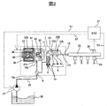
- FIG. 2 is a diagram showing an example of the overall configuration of a fuel supply system including a fuel supply pump to which the present invention can be applied.
- a portion 1 surrounded by a broken line indicates a fuel supply pump main body, and the mechanisms and components shown in the broken line indicate that the fuel supply pump main body 1 is integrally incorporated.
- Fuel is fed from the fuel tank 20 to the fuel supply pump main body 1 via the feed pump 21, and pressurized fuel is sent from the fuel supply pump main body 1 to the injector 24 side.
- the engine control unit (control unit) 27 takes in the fuel pressure from the pressure sensor 26 and controls the feed pump 21, the electromagnetic coil 43 in the fuel supply pump main body 1, and the injector 24 in order to optimize this.
- the fuel in the fuel tank 20 is first pumped up by a feed pump 21 based on a control signal S 1 from an engine control unit (control unit) 27, pressurized to an appropriate feed pressure, and fed through a suction pipe 28.
- 1 low-pressure fuel inlet (suction joint) 10a The fuel that has passed through the low-pressure fuel suction port 10a reaches the suction port 31b of the electromagnetic suction valve 300 that constitutes the variable capacity mechanism via the pressure pulsation reducing mechanism 9 and the suction passage 10d.
- the pressure pulsation reducing mechanism 9 communicates with the annular low-pressure fuel chamber 7a, which makes the pressure variable in conjunction with the plunger 2 that reciprocates by an engine cam mechanism (not shown). The pulsation of the fuel pressure sucked into the suction port 31b is reduced.
- the fuel that has flowed into the suction port 31 b of the electromagnetic suction valve 300 passes through the suction valve 30 and flows into the pressurizing chamber 11.
- the valve position of the intake valve 30 is determined by controlling the electromagnetic coil 43 in the fuel supply pump main body 1 based on the control signal S2 from the engine control unit (control unit) 27.
- the reciprocating power is given to the plunger 2 by an engine cam mechanism (not shown). Due to the reciprocating motion of the plunger 2, fuel is sucked from the suction valve 30 in the lowering process of the plunger 2, and the sucked fuel is pressurized in the lifting process of the plunger 2, and the pressure sensor 26 is mounted via the discharge valve mechanism 8.
- Fuel is pumped to the common rail 23. Thereafter, the injector 24 injects fuel into the engine based on a control signal S3 from the engine control unit (control unit) 27.
- the discharge valve mechanism 8 provided at the outlet of the pressurizing chamber 11 includes a discharge valve sheet 8a, a discharge valve 8b that contacts and separates from the discharge valve sheet 8a, and a discharge that urges the discharge valve 8b toward the discharge valve sheet 8a. It is comprised by the valve spring 8c etc. According to the discharge valve mechanism 8, the discharge valve 8b opens when the internal pressure of the pressurizing chamber 11 is higher than the pressure on the discharge passage 12 downstream of the discharge valve 8b and overcomes the drag determined by the discharge valve spring 8c. The pressurized fuel is pumped from the pressurizing chamber 11 to the discharge passage 12 side.
- 30 is a suction valve
- 35 is a rod for controlling the position of the suction valve
- 36 is an anchor portion
- 33 is a suction valve spring
- 40 is a rod biasing spring
- 41 is an anchor portion biasing spring.
- the intake valve 30 is urged in the valve closing direction by the intake valve spring 33, and is urged in the valve opening direction by the rod urging spring 40 via the rod 35.
- the anchor portion 36 is biased in the valve closing direction by an anchor portion biasing spring.
- the valve position of the suction valve 30 is controlled by driving the rod 35 by the electromagnetic coil 43.
- the fuel supply pump 1 is configured such that the electromagnetic coil 43 in the fuel supply pump main body 1 is controlled by the control signal S2 given to the electromagnetic intake valve 300 by the engine control unit (control unit) 27, and the common rail is connected via the discharge valve mechanism 8.
- the fuel flow rate is discharged so that the fuel pumped to 23 becomes a desired supply fuel.
- the pressurizing chamber 11 and the common rail 23 are communicated by a relief valve 100.
- the relief valve 100 is a valve mechanism arranged in parallel with the discharge valve mechanism 8. In the relief valve 100, when the pressure on the common rail 23 side exceeds the set pressure of the relief valve 100, the relief valve 100 is opened and the fuel is returned to the pressurizing chamber 11 of the fuel supply pump 1, whereby the pressure in the common rail 23 is increased. Prevent abnormal high pressure conditions.
- the relief valve 100 forms a high-pressure channel 110 that communicates the discharge passage 12 on the downstream side of the discharge valve 8b in the fuel supply pump body 1 and the pressurizing chamber 11, and is provided so as to bypass the discharge valve 8b. It is what was done.
- the high-pressure channel 110 is provided with a relief valve 102 that restricts the flow of fuel in only one direction from the discharge channel to the pressurizing chamber 11.
- the relief valve 102 is pressed against the relief valve seat 101 by a relief spring 105 that generates a pressing force, and the pressure difference between the pressure chamber 11 and the high-pressure channel 110 is determined by the relief spring 105. If it becomes above, it is set so that the relief valve 102 may leave
- the differential pressure between the discharge passage 110 and the pressurizing chamber 11 becomes equal to or higher than the valve opening pressure of the relief valve 102. Then, the relief valve 102 is opened, and the fuel having an abnormally high pressure is returned from the discharge passage 110 to the pressurizing chamber 11 to protect the high-pressure section piping such as the common rail 23.
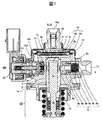
- FIG. 1 is a diagram showing a specific example of a fuel supply pump body 1 that is mechanically integrated. According to this figure, a plunger 2 that reciprocates (in this case, up and down) by an engine cam mechanism (not shown) in the central height direction shown in the figure is arranged in the cylinder 6, A pressurizing chamber 11 is formed.
- the mechanism on the electromagnetic suction valve 300 side is disposed on the left side of the center of the figure, and the discharge valve mechanism 8 is disposed on the right side of the center of the figure.
- a low-pressure fuel suction port 10a, a pressure pulsation reduction mechanism 9, a suction passage 10d, and the like are disposed as a fuel suction side mechanism.
- a plunger internal combustion engine side mechanism 150 is described in the lower center portion of FIG.
- the plunger internal combustion engine side mechanism 150 is a portion that is embedded and fixed in the internal combustion engine body as shown in FIG.
- the relief valve 100 mechanism is not shown in the display cross section of FIG.
- the relief valve 100 mechanism can be displayed in a display section at a different angle, but since it is not directly related to the present invention, explanation and display are omitted.
- FIG. 3 shows a state in which the mounting root (plunger internal combustion engine side mechanism) 150 is embedded and fixed in the internal combustion engine body.
- the attachment root 150 since the attachment root 150 is described as a center, description of other parts is omitted.
- reference numeral 90 denotes a thick portion of the cylinder head of the internal combustion engine.
- An attachment root attaching hole 95 is formed in advance in the cylinder head 90 of the internal combustion engine.
- the attachment root portion mounting hole 95 is configured with a two-stage diameter according to the shape of the attachment root portion 150, and the attachment root portion 150 is fitted and disposed in the root portion attachment hole 95.
- the mounting root 150 is airtightly fixed to the cylinder head 90 of the internal combustion engine.
- the fuel supply pump is in close contact with the plane of the cylinder head 90 of the internal combustion engine using a flange 1 e provided in the pump body 1 and fixed with a plurality of bolts 91.
- the mounting flange 1e is welded to the pump body 1 at the welded portion 1f to form an annular fixed portion.
- laser welding is used for welding the welded portion 1f.
- an O-ring 61 is fitted into the pump body 1 for sealing between the cylinder head 90 and the pump body 1 to prevent engine oil from leaking to the outside.
- the plunger root 150 arranged in an airtight manner in this manner is provided with a tappet 92 that converts the rotational movement of the cam 93 attached to the camshaft of the internal combustion engine into a vertical movement and transmits it to the plunger 2 at the lower end 2b of the plunger 2. It has been.
- the plunger 2 is pressure-bonded to the tappet 92 by the spring 4 through the retainer 15. Thereby, the plunger 2 is reciprocated up and down with the rotational movement of the cam 93.
- a plunger seal 13 held at the lower end of the inner periphery of the seal holder 7 is installed in a state in which the plunger seal 13 slidably contacts the outer periphery of the plunger 2 in the lower part of the cylinder 6 in the figure.
- the fuel can be sealed even when the plunger 2 slides to prevent the fuel from leaking to the outside.
- lubricating oil including engine oil
- for lubricating the sliding portion in the internal combustion engine is prevented from flowing into the pump body 1.
- the plunger root 150 arranged in an airtight manner reciprocates within the cylinder 6 as the plunger 2 inside the plunger 2 rotates.
- a cylinder in which a fuel supply pump main body 1 guides the reciprocating motion of a plunger 2 and has an end (upper side in FIG. 1) formed in a bottomed cylindrical shape so as to form a pressurizing chamber 11 therein. 6 is attached.
- the pressurizing chamber 11 is connected to an electromagnetic suction valve 300 for supplying fuel and a discharge valve mechanism 8 for discharging fuel from the pressurizing chamber 11 to the discharge passage.
- a plurality of communication holes 6b are provided to communicate the groove 6a with the pressurizing chamber.
- the cylinder 6 is press-fitted and fixed to the fuel supply pump main body 1 at the outer diameter, and is sealed with a press-fitted portion cylindrical surface so that fuel pressurized from the gap with the fuel supply pump main body 1 does not leak to the low pressure side.
- the cylinder 6 has a small-diameter portion 6 c at the outer diameter on the pressurizing chamber side.
- the cylinder 6 exerts a force on the low pressure fuel chamber 10c side.
- the pump body 1 with the small diameter portion 1a the cylinder 6 is pulled out on the low pressure fuel chamber 10c side. To prevent that.
- By bringing the surfaces into contact with a plane in the axial direction in addition to the sealing of the contact cylindrical surface of the fuel supply pump main body 1 and the cylinder 6, it also functions as a double seal.
- a damper cover 14 is fixed to the head of the fuel supply pump main body 1.
- the damper cover 14 is provided with a suction joint 51 and forms a low-pressure fuel suction port 10a.
- the fuel that has passed through the low-pressure fuel suction port 10a passes through the filter 52 fixed inside the suction joint 51, and reaches the suction port 31b of the electromagnetic suction valve 300 via the pressure pulsation reducing mechanism 9 and the low-pressure fuel flow path 10d. .
- the suction filter 52 in the suction joint 51 serves to prevent foreign matter existing between the fuel tank 20 and the low-pressure fuel inlet 10a from being absorbed into the fuel supply pump by the flow of fuel.
- the plunger 2 has a large-diameter portion 2a and a small-diameter portion 2b, so that the volume of the annular low-pressure fuel chamber 7a increases and decreases by the reciprocating motion of the plunger.
- the volume increase / decrease is communicated with the low-pressure fuel chamber 10 by the fuel passage 1d (FIG. 3), so that when the plunger 2 is lowered, the pressure is reduced from the annular low-pressure fuel chamber 7a to the low-pressure fuel chamber 10; A fuel flow is generated from the fuel chamber 10 to the annular low-pressure fuel chamber 7a.
- the low pressure fuel chamber 10 is provided with a pressure pulsation reducing mechanism 9 for reducing the pressure pulsation generated in the fuel supply pump from spreading to the fuel pipe 28 (FIG. 2).
- a pressure pulsation reducing mechanism 9 for reducing the pressure pulsation generated in the fuel supply pump from spreading to the fuel pipe 28 (FIG. 2).
- the pressure pulsation reducing mechanism 9 provided in the low-pressure fuel chamber 10 is formed of a metal damper in which two corrugated disk-shaped metal plates are bonded together on the outer periphery and an inert gas such as argon is injected inside. The pressure pulsation is absorbed and reduced as the metal damper expands and contracts.
- Reference numeral 9b denotes a mounting bracket for fixing the metal damper to the inner peripheral portion of the fuel supply pump main body 1, and since it is installed on the fuel passage, a plurality of holes are provided to allow fluid to freely flow between the front and back of the mounting bracket 9b. I can do it.
- the discharge valve mechanism 8 provided at the outlet of the pressurizing chamber 11 includes a discharge valve sheet 8a, a discharge valve 8b that contacts and separates from the discharge valve sheet 8a, and a discharge valve spring that urges the discharge valve 8b toward the discharge valve sheet 8a. 8c, a discharge valve holder 8d that accommodates the discharge valve 8b and the discharge valve seat 8a.
- the discharge valve sheet 8a and the discharge valve holder 8d are joined by welding at a contact portion 8e to form an integral discharge valve mechanism 8. Forming.
- a stepped portion 8f that forms a stopper that restricts the stroke of the discharge valve 8b is provided inside the discharge valve holder 8d.
- the stroke is too large, and the fuel discharged at high pressure to the fuel discharge port 12 due to the delay in closing the discharge valve 8b can be prevented from flowing back into the pressurizing chamber 11 again, and the efficiency of the fuel supply pump is reduced. Can be suppressed.
- the discharge valve 8b repeats opening and closing movements, the discharge valve 8b is guided on the inner peripheral surface of the discharge valve holder 8d so as to move only in the stroke direction. By doing so, the discharge valve mechanism 8 becomes a check valve that restricts the flow direction of fuel.
- FIGS. 4 shows the state in the suction process among the steps of suction, return, and discharge in the pump operation
- FIGS. 5 and 6 show the state in the discharge process.
- the structure on the electromagnetic suction valve 300 side is mainly composed of a suction valve part A mainly composed of the suction valve 30, a solenoid mechanism part B mainly composed of the rod 35 and the anchor part 36, and an electromagnetic coil 43.
- the intake valve portion A includes an intake valve 30, an intake valve seat 31, an intake valve stopper 32, an intake valve biasing spring 33, and an intake valve holder 34.
- the suction valve seat 31 is cylindrical, and has a seat portion 31a in the axial direction on the inner peripheral side and a plurality of suction passage portions 31b radially about the cylindrical axis.
- the intake valve holder 34 has claws in two or more directions radially, and the outer peripheral side of the claws is fitted and held coaxially on the inner peripheral side of the intake valve seat 31. Further, a suction valve stopper 32 having a cylindrical shape and a collar shape at one end is fitted and held on the inner peripheral cylindrical surface of the suction valve holder 34.
- the suction valve urging spring 33 is disposed on the inner peripheral side of the suction valve stopper 32 in a small diameter part for stabilizing one end of the spring coaxially, and the suction valve 30 is inhaled with the suction valve seat part 31a. Between the valve stoppers 32, a suction valve biasing spring 33 is fitted into the valve guide portion 30b.
- the suction valve urging spring 33 is a compression coil spring and is installed so that the urging force acts in a direction in which the suction valve 30 is pressed against the suction valve seat portion 31a. It is not limited to the compression coil spring, and any form may be used as long as it can obtain an urging force, and a leaf spring having an urging force integrated with the suction valve may be used.
- the suction valve portion A By configuring the suction valve portion A in this way, in the pump suction process, the fuel that has passed through the suction passage 31b and entered the interior passes between the suction valve 30 and the seat portion 31a, and the suction valve 30 The fuel passes through between the outer peripheral side and the claw of the suction valve holder 34, passes through the passage of the fuel supply pump main body 1 and the cylinder, and flows the fuel into the pressurizing chamber. Further, in the pump discharge process, the intake valve 30 performs contact sealing with the intake valve seat portion 31a, thereby fulfilling the function of a check valve that prevents backflow of fuel to the inlet side.
- a passage 32 a is provided in order to release the hydraulic pressure on the inner peripheral side of the suction valve stopper according to the movement of the suction valve 30.
- the axial movement amount 30e of the suction valve 30 is limited by the suction valve stopper 32. This is because if the amount of movement is too large, the reverse flow rate increases due to a response delay when the intake valve 30 is closed, and the performance as a pump decreases.
- the restriction of the movement amount can be defined by the axial shape and size of the suction valve seat 31a, the suction valve 30, and the suction valve stopper 32, and the fixed position.
- the suction valve stopper 32 is provided with a protrusion 32b so that the contact area with the suction valve stopper 32 is reduced when the suction valve 32 is open. This is because the intake valve 32 is likely to be separated from the intake valve stopper 32 during the transition from the open state to the closed state, that is, the valve closing response is improved.
- a large squeeze force acts between the intake valve 30 and the intake valve stopper 32, and the intake valve 30 is difficult to be separated from the intake valve 32.
- the suction valve 30, the suction valve seat 31a, and the suction valve stopper 32 are made of a heat-treated martensitic stainless steel that has high strength, high hardness, and excellent corrosion resistance in order to repeatedly collide with each other.
- the suction valve spring 33 and the suction valve holder 34 are made of austenitic stainless steel in consideration of corrosion resistance.
- the solenoid mechanism part B includes a rod 35 that is a movable part, an anchor part 36, a rod guide 37 that is a fixed part, an outer core 38, a fixed core 39, a rod biasing spring 40, and an anchor part biasing spring 41.
- the rod 35 and the anchor part 36 which are movable parts are configured as separate members.
- the rod 35 is slidably held in the axial direction on the inner peripheral side of the rod guide 37, and the inner peripheral side of the anchor portion 36 is slidably held on the outer peripheral side of the rod 35. That is, both the rod 35 and the anchor portion 36 are configured to be slidable in the axial direction as long as they are geometrically restricted.
- the anchor portion 36 has one or more through holes 36a penetrating in the axial direction of the component in order to move freely and smoothly in the axial direction in the fuel, and eliminates the restriction of movement due to the pressure difference before and after the anchor portion as much as possible. .
- the rod guide 37 is inserted in the radial direction on the inner peripheral side of the hole into which the intake valve of the fuel supply pump main body 1 is inserted, and in the axial direction, is abutted against one end portion of the intake valve seat.
- the outer core 38 that is fixed to the main body 1 by welding and the fuel supply pump main body 1 are arranged in a sandwiched manner.
- the rod guide 37 is also provided with a through hole 37a penetrating in the axial direction in the same manner as the anchor portion 36, and the pressure of the fuel chamber on the anchor portion side controls the movement of the anchor portion so that the anchor portion can move freely and smoothly. It is configured not to interfere.
- the outer core 38 has a thin cylindrical shape on the side opposite to the portion to be welded with the fuel supply pump main body, and is fixed by welding in such a manner that the fixed core 39 is inserted on the inner peripheral side thereof.
- a rod urging spring 40 is arranged on the inner peripheral side of the fixed core 39 with the narrow diameter portion as a guide, the rod 35 comes into contact with the suction valve 30, and the suction valve is pulled away from the suction valve seat portion 31a, that is, suction. Energizing force is applied in the valve opening direction.
- the anchor portion biasing spring 41 is disposed so as to apply a biasing force to the anchor portion 36 in the direction of the rod collar portion 35a while inserting one end into a cylindrical central bearing portion 37b provided on the center side of the rod guide 37 and maintaining the same axis. It is said.
- the movement amount 36e of the anchor portion 36 is set to be larger than the movement amount 30e of the intake valve 30. This is because the intake valve 30 is surely closed.
- the intake valve portion A and the solenoid mechanism portion B are configured by organically arranging three springs.
- the suction valve biasing spring 33 configured in the suction valve unit A, the rod biasing spring 40 and the anchor unit biasing spring 41 configured in the solenoid mechanism unit B correspond to this.
- any spring uses a coil spring, but any spring can be used as long as it can obtain an urging force.
- the coil portion C includes a first yoke 42, an electromagnetic coil 43, a second yoke 44, a bobbin 45, a terminal 46, and a connector 47.
- a coil 43 in which a copper wire is wound around the bobbin 45 is disposed so as to be surrounded by the first yoke 42 and the second yoke 44, and is molded and fixed integrally with a connector which is a resin member.
- the respective ends of the two terminals 46 are respectively connected to both ends of the copper wire of the coil so as to be energized.
- the terminal 46 is molded integrally with the connector, and the remaining end can be connected to the engine control unit side.
- the coil part C is fixed by press-fitting the hole at the center of the first yoke 42 into the outer core 38. At that time, the inner diameter side of the second yoke 44 is in contact with the fixed core 39 or close to a slight clearance.
- Both the first yoke 42 and the second yoke 44 are made of magnetic stainless steel in order to constitute a magnetic circuit and in consideration of corrosion resistance, and the bobbin 45 and the connector 47 are made of high strength heat resistant resin in consideration of strength characteristics and heat resistance characteristics.
- the coil 43 is made of copper, and the terminal 46 is made of brass plated with metal.
- the outer core 38, the first yoke 42, the second yoke 44, the fixed core 39, the anchor part 36 As shown by the arrow part in FIG.
- a magnetic circuit is formed and a current is applied to the coil, a magnetic attractive force is generated between the fixed core 39 and the anchor portion 36, and a force attracted to each other is generated.
- the axial portion where the fixed core 39 and the anchor portion 36 generate the magnetic attractive force is made as thin as possible, so that almost all of the magnetic flux passes between the fixed core 39 and the anchor portion 36. The magnetic attractive force can be obtained efficiently.
- the operation is performed as follows in each step of suction, return, and discharge in the pump operation.
- the inhalation process will be described.
- the plunger 2 moves in the direction of the cam 93 (the plunger 2 is lowered) by the rotation of the cam 93 in FIG. That is, the position of the plunger 2 is moved from the top dead center to the bottom dead center.
- the suction process state for example, referring to FIG. 1, the volume of the pressurizing chamber 11 increases and the fuel pressure in the pressurizing chamber 11 decreases.
- FIG. 4 The positional relationship of each part on the electromagnetic suction valve 300 side in the suction process is shown in FIG. 4 and will be described with reference to FIG. In this state, the electromagnetic coil 43 remains in a non-energized state and no magnetic biasing force is acting. Therefore, the suction valve 30 is pressed against the rod 35 by the urging force of the rod urging spring 40 and remains open.
- the plunger 2 moves in the upward direction by the rotation of the cam 93 in FIG. That is, the plunger 2 position starts to move from the bottom dead center to the top dead center.
- the volume of the pressurizing chamber 11 decreases with the compression motion after the suction in the plunger 2, but in this state, the fuel once sucked into the pressurizing chamber 11 is again sucked through the suction valve 30 in the valve open state. Since the pressure is returned to the passage 10d, the pressure in the pressurizing chamber does not increase. This process is called a return process.
- FIG. 5 shows the positional relationship of the respective parts on the electromagnetic suction valve 300 side when the magnetic attractive force is applied, and this will be described with reference to FIG.
- a magnetic circuit is formed by the outer core 38, the first yoke 42, the second yoke 44, the fixed core 39, and the anchor portion 36.
- a force is generated and a force that is attracted to each other is generated.
- the anchor portion 36 is sucked by the fixed core 39 which is a fixed portion, the rod 35 moves in a direction away from the intake valve 30 by the locking mechanism of the anchor portion 36 and the rod collar portion 35a.
- the suction valve 30 is closed by the biasing force of the suction valve biasing spring 33 and the fluid force caused by the fuel flowing into the suction passage 10d.
- the fuel pressure in the pressurizing chamber 11 rises with the upward movement of the plunger 2, and when the pressure exceeds the pressure at the fuel discharge port 12, high-pressure discharge of fuel is performed via the discharge valve mechanism 8, and to the common rail 23. Supplied. This process is called a discharge process.
- the compression process of the plunger 2 includes a return process and a discharge process.
- the quantity of the high-pressure fuel discharged can be controlled by controlling the energization timing to the coil 43 of the electromagnetic suction valve 300. If the timing of energizing the electromagnetic coil 43 is advanced, the ratio of the return process in the compression process is small and the ratio of the discharge process is large. That is, the amount of fuel returned to the suction passage 10d is small and the amount of fuel discharged at high pressure is large. On the other hand, if the timing of energization is delayed, the ratio of the return process in the compression process is large and the ratio of the discharge process is small. That is, the amount of fuel returned to the suction passage 10d is large, and the amount of fuel discharged at high pressure is small.
- the energization timing to the electromagnetic coil 43 is controlled by a command from the engine control unit (control unit) 27.
- the amount of fuel discharged at high pressure can be controlled to the amount required by the internal combustion engine by controlling the timing of energizing the electromagnetic coil 43.
- FIG. 6 shows the positional relationship of each part on the electromagnetic suction valve 300 side in the discharge process.
- a diagram of a non-energized state in which the energization of the electromagnetic coil 43 is released in a state where the suction valve is closed after the pressure in the pressurizing chamber has sufficiently increased is shown.
- a system is in place to effectively generate and act the next magnetic attractive force. This structure is characterized by the establishment of this system.
- suction valve holder 34 is integrated with the suction valve stopper 32 and the flow path structure of the present invention is formed by the shape thereof will be described as an example.
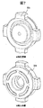
- the shape of the suction valve stopper 32 in this embodiment is shown in FIG.
- the purpose of this embodiment is to secure a sufficient flow path cross-sectional area with a simple structure with a small number of processing steps, and to prevent an increase in pressure loss even when the flow rate of discharged fuel is increased.
- the detailed structure for this will be described below.
- the suction valve stopper 32 is provided with a fixed portion 32c on the outermost periphery thereof, and this portion is fitted and held in the inner peripheral cylindrical surface of the housing portion 31c. Further, a disc-like overlapping portion 32d is provided near the center portion, and the suction valve 30 is arranged on the side surface.
- FIG. 8 shows a cross-sectional view of the suction valve portion A when the suction valve stopper 32 shown in FIG. 7 is assembled.
- a vertical sectional view is shown in the upper stage, and a 45 degree sectional view is shown in the lower stage.
- the overlapping portion 32d is disposed between the pressurizing chamber 11 and the suction valve 30 and overlaps the suction valve 30 in the suction valve axial direction, and is formed integrally with the overlapping portion 32d on the outer peripheral side of the outer peripheral side surface of the overlapping portion 32d.
- a plurality of fixing portions 32c for fixing the overlapping portion 32d for fixing the overlapping portion 32d.
- the 1st flow path 32e is formed between the outer peripheral side surface of the overlap part 32d, and the housing part 31c arrange
- the first flow path 32e and the second flow path 32f are formed so as to be continuously connected by the housing portion 31c while being connected to the second flow path 32f closer to the pressurization chamber than the side surface of the pressurization chamber.
- the plurality of fixing portions 32c are configured to be positioned on the pressure chamber side with respect to the suction valve side surface of the overlapping portion 32d, and the outer peripheral side surface of the overlapping portion 32d and the suction valve side of the plurality of fixing portions 32c are arranged.
- a first flow path 32e is formed by the surface, and a second flow path 32f that connects the first flow path 32e and the pressurizing chamber 11 is formed between adjacent fixing portions 32d.
- the thickness of the plurality of fixed portions 32c in the suction valve axial direction is configured to be thinner than the thickness of the overlapping portion 32d in the suction valve axial direction, and the surface on the pressure chamber side of the plurality of fixed portions 32c is You may comprise so that it may be located in the suction valve side rather than the surface by the side of the pressurization chamber of the overlap part 32d.
- the flow path cross-sectional area of the second flow path 32f is smaller than the first flow path 32e by the fixed portion 32c, and the contribution to the pressure loss is large.
- the axial distance of the second flow path 32f that greatly contributes to pressure loss can be shortened, which is advantageous from the viewpoint of reducing pressure loss. .
- the overlapping portion 32d comes into contact with the suction valve 30 so that the suction valve stopper 32 restricts the movement in the valve opening direction, or the overlapping portion 32d.
- biases the suction valve 30 in the valve closing direction may be formed.
- the plurality of fixing portions 32d have a press-fit portion 32i that is press-fitted into the inner peripheral surface of the hole 1c formed in the pump body 1 or the inner peripheral surface of the housing portion 31c on the outer peripheral side.
- the overlapping portion 32d and the plurality of fixing portions 32c are preferably formed of a pressed part or a forged part.
- the plurality of fixing portions 32c are arranged at a predetermined interval in the circumferential direction on the outer peripheral side of the outermost peripheral end portion of the outer peripheral side surface of the overlapping portion 32d, and the second flow path 32f is overlapped. It forms in the outer peripheral side rather than the outermost peripheral edge part of the outer peripheral side surface of the part 32d. Further, the outermost peripheral end portion of the outer peripheral side surface of the overlapping portion 32 c is configured to be positioned on the outer peripheral side with respect to the outermost peripheral end portion of the outer peripheral surface of the suction valve 30.
- FIG. 9 shows the shape of the suction valve stopper 32 according to the present embodiment.
- a feature is that a portion (shown by a dotted line) between a plurality of adjacent fixing portions 32c is excluded.
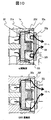
- FIG. 10 shows a cross-sectional view of the suction valve portion A when the suction valve stopper 32 shown in FIG. 9 is assembled. A vertical sectional view is shown in the upper stage, and a 45 degree sectional view is shown in the lower stage.
- the plurality of fixing portions 32c are configured to be positioned on the pressure chamber side with respect to the suction valve side surface of the overlapping portion 32d, and the outer peripheral side surface of the overlapping portion 32d and the suction valve side surface of the plurality of fixing portions 32c
- the first flow path 32e is formed
- the second flow path 32f that connects the first flow path 32e and the pressurizing chamber 11 is formed between the adjacent fixing portions 32c.
- the plurality of fixing portions 32c overlap with the inner peripheral surface of the plurality of fixing portions 32c in the suction valve axial direction, and the space 32g is closer to the pressurizing chamber than the pressurizing chamber side surface of the overlapping portion 32d.
- the space 32g is formed so as to form a part of the second flow path 32f. By doing so, the second flow path 32f is enlarged in the radial direction more than the projected area seen from the axial direction, and a larger cross-sectional area can be secured with a simple structure, which is advantageous for reducing pressure loss. It
- the plurality of fixing portions 32c are formed by pressing the plurality of fixing portions 32c toward the axial pressure chamber side with respect to the overlapping portion 32d by a press manufacturing method or a forging manufacturing method. Is configured to be arranged closer to the pressurizing chamber than the surface of the overlapping portion 32d on the pressurizing chamber side.
- the plurality of fixing portions 32c are configured so that substantially all of the fixing portions 32c are arranged closer to the pressurizing chamber side than the end portion on the pressurizing chamber side of the surface of the overlapping portion 32d on the pressurizing chamber side.
- the suction valve stopper 32 may be provided with a spring holding portion 32h as in the case of the first embodiment.
- the overlapping portion 32d has a recess 32j that is recessed toward the pressurizing chamber on the inner peripheral side, and holds the spring 33 that biases the suction valve 30 in the valve closing direction in the recess 32j.
- fixed part 32c are substantially the same in the suction valve axial direction.
- the flow passage cross-sectional area is secured larger than that of the first embodiment with a simple structure with fewer processing steps, and even when the flow rate of discharged fuel is increased, the pressure loss is reduced. It is possible to provide an intake valve that prevents the increase and realizes highly accurate flow rate control, and a low-cost fuel supply pump to which the intake valve is applied.
- the present invention is not limited to the above-described embodiment, and includes various modifications.
- the embodiments have been described in detail for easy understanding of the present invention, and are not necessarily limited to those having all the configurations described.
- a part of the configuration of a certain embodiment can be replaced with the configuration of another embodiment, and the configuration of another embodiment can be added to the configuration of a certain embodiment.
Landscapes
- Engineering & Computer Science (AREA)
- Chemical & Material Sciences (AREA)
- Combustion & Propulsion (AREA)
- Mechanical Engineering (AREA)
- General Engineering & Computer Science (AREA)
- Fuel-Injection Apparatus (AREA)
Abstract
L'objectif de la présente invention est de fournir : une soupape d'aspiration qui a une structure simple nécessitant un petit nombre d'heures de main-d'oeuvre pour le traitement et qui fournit une surface en section transversale de trajet d'écoulement suffisante pour permettre une régulation de débit de haute précision tout en empêchant une augmentation de la perte de pression même lorsque le débit du carburant déchargé est élevé; et une pompe d'alimentation en carburant de faible coût utilisant la soupape d'aspiration. L'objectif susmentionné peut être atteint par une pompe d'alimentation en carburant pourvue d'un corps de pompe dans lequel est formée une chambre de pressurisation, et d'une soupape d'aspiration disposée sur le côté aspiration de la chambre de pressurisation, la pompe d'alimentation en carburant comprenant en outre : une partie de chevauchement qui est disposée entre la chambre de pressurisation et la soupape d'aspiration et qui chevauche la soupape d'aspiration dans la direction axiale de la soupape d'aspiration; et une pluralité de parties de fixation qui, sur un côté plus proche d'une périphérie externe qu'une surface côté périphérie externe de la partie de chevauchement, sont formées d'un seul tenant avec la partie de chevauchement, et fixent la partie de chevauchement, un premier trajet d'écoulement étant formé entre la surface côté périphérie externe de la partie de chevauchement et une partie de boîtier disposée sur un côté plus proche de la périphérie externe que la surface côté périphérie externe de la partie de chevauchement, le premier trajet d'écoulement étant relié à un second trajet d'écoulement sur un côté plus proche de la chambre de pressurisation qu'une surface côté chambre de pressurisation de la partie de chevauchement, et le premier trajet d'écoulement et le second trajet d'écoulement étant formés de manière à être reliés de manière contiguë par la partie de boîtier.
Applications Claiming Priority (2)
| Application Number | Priority Date | Filing Date | Title |
|---|---|---|---|
| JP2016105757A JP6685176B2 (ja) | 2016-05-27 | 2016-05-27 | 燃料供給ポンプ |
| JP2016-105757 | 2016-05-27 |
Publications (1)
| Publication Number | Publication Date |
|---|---|
| WO2017203812A1 true WO2017203812A1 (fr) | 2017-11-30 |
Family
ID=60412280
Family Applications (1)
| Application Number | Title | Priority Date | Filing Date |
|---|---|---|---|
| PCT/JP2017/011297 Ceased WO2017203812A1 (fr) | 2016-05-27 | 2017-03-22 | Pompe d'alimentation en carburant |
Country Status (2)
| Country | Link |
|---|---|
| JP (1) | JP6685176B2 (fr) |
| WO (1) | WO2017203812A1 (fr) |
Families Citing this family (1)
| Publication number | Priority date | Publication date | Assignee | Title |
|---|---|---|---|---|
| WO2019230064A1 (fr) * | 2018-05-30 | 2019-12-05 | 日立オートモティブシステムズ株式会社 | Pompe d'alimentation en combustible |
Citations (4)
| Publication number | Priority date | Publication date | Assignee | Title |
|---|---|---|---|---|
| JP2005514571A (ja) * | 2002-01-07 | 2005-05-19 | シーメンス アクチエンゲゼルシヤフト | ポンプのための入口弁もしくは出口弁 |
| JP2012154295A (ja) * | 2011-01-28 | 2012-08-16 | Denso Corp | 高圧ポンプ |
| JP2014141896A (ja) * | 2013-01-22 | 2014-08-07 | Denso Corp | 高圧ポンプ |
| JP2015057554A (ja) * | 2014-12-26 | 2015-03-26 | 日立オートモティブシステムズ株式会社 | 電磁駆動型の吸入弁を備えた高圧燃料供給ポンプ |
-
2016
- 2016-05-27 JP JP2016105757A patent/JP6685176B2/ja active Active
-
2017
- 2017-03-22 WO PCT/JP2017/011297 patent/WO2017203812A1/fr not_active Ceased
Patent Citations (4)
| Publication number | Priority date | Publication date | Assignee | Title |
|---|---|---|---|---|
| JP2005514571A (ja) * | 2002-01-07 | 2005-05-19 | シーメンス アクチエンゲゼルシヤフト | ポンプのための入口弁もしくは出口弁 |
| JP2012154295A (ja) * | 2011-01-28 | 2012-08-16 | Denso Corp | 高圧ポンプ |
| JP2014141896A (ja) * | 2013-01-22 | 2014-08-07 | Denso Corp | 高圧ポンプ |
| JP2015057554A (ja) * | 2014-12-26 | 2015-03-26 | 日立オートモティブシステムズ株式会社 | 電磁駆動型の吸入弁を備えた高圧燃料供給ポンプ |
Also Published As
| Publication number | Publication date |
|---|---|
| JP6685176B2 (ja) | 2020-04-22 |
| JP2017210935A (ja) | 2017-11-30 |
Similar Documents
| Publication | Publication Date | Title |
|---|---|---|
| JP6293290B2 (ja) | 高圧燃料供給ポンプ | |
| JP6869005B2 (ja) | 燃料供給ポンプ | |
| CN108026879B (zh) | 高压燃料泵 | |
| CN102197212A (zh) | 高压燃料供给泵 | |
| EP3467297B1 (fr) | Pompe d'alimentation en carburant haute pression | |
| JP6779370B2 (ja) | 高圧燃料ポンプ | |
| JP6235518B2 (ja) | 高圧燃料供給ポンプ及び高圧燃料供給ポンプの組立て方法 | |
| JP2016142143A (ja) | 高圧燃料供給ポンプ | |
| JP2021014791A (ja) | 高圧燃料ポンプ | |
| JP2018087548A (ja) | 高圧燃料供給ポンプ | |
| CN110651117B (zh) | 阀机构、电磁吸入阀机构以及高压燃料泵 | |
| WO2017208565A1 (fr) | Dispositif de commande d'une pompe d'alimentation en carburant à haute pression, et pompe d'alimentation en carburant à haute pression | |
| US12140113B2 (en) | Electromagnetic valve mechanism and fuel pump | |
| JP6685176B2 (ja) | 燃料供給ポンプ | |
| JP2017145731A (ja) | 高圧燃料供給ポンプ | |
| JP7178504B2 (ja) | 燃料ポンプ | |
| JP6770193B2 (ja) | 高圧燃料供給ポンプ | |
| JP6754902B2 (ja) | 電磁吸入弁、及びこれを備えた高圧燃料ポンプ | |
| JP7024071B2 (ja) | 燃料供給ポンプ | |
| JP6602692B2 (ja) | 高圧燃料供給ポンプの制御方法及びそれを用いた高圧燃料供給ポンプ。 | |
| JP7077212B2 (ja) | 高圧燃料ポンプ | |
| JP6932629B2 (ja) | 高圧燃料ポンプ | |
| WO2020085041A1 (fr) | Mécanisme de soupape électromagnétique et pompe à carburant haute pression |
Legal Events
| Date | Code | Title | Description |
|---|---|---|---|
| 121 | Ep: the epo has been informed by wipo that ep was designated in this application |
Ref document number: 17802414 Country of ref document: EP Kind code of ref document: A1 |
|
| NENP | Non-entry into the national phase |
Ref country code: DE |
|
| 122 | Ep: pct application non-entry in european phase |
Ref document number: 17802414 Country of ref document: EP Kind code of ref document: A1 |