WO2017204205A1 - 微細気泡混合液の製造装置および製造方法 - Google Patents
微細気泡混合液の製造装置および製造方法 Download PDFInfo
- Publication number
- WO2017204205A1 WO2017204205A1 PCT/JP2017/019156 JP2017019156W WO2017204205A1 WO 2017204205 A1 WO2017204205 A1 WO 2017204205A1 JP 2017019156 W JP2017019156 W JP 2017019156W WO 2017204205 A1 WO2017204205 A1 WO 2017204205A1
- Authority
- WO
- WIPO (PCT)
- Prior art keywords
- liquid
- storage tank
- bubbles
- liquid storage
- cylinder
- Prior art date
- Legal status (The legal status is an assumption and is not a legal conclusion. Google has not performed a legal analysis and makes no representation as to the accuracy of the status listed.)
- Ceased
Links
Images



Classifications
-
- B—PERFORMING OPERATIONS; TRANSPORTING
- B01—PHYSICAL OR CHEMICAL PROCESSES OR APPARATUS IN GENERAL
- B01F—MIXING, e.g. DISSOLVING, EMULSIFYING OR DISPERSING
- B01F23/00—Mixing according to the phases to be mixed, e.g. dispersing or emulsifying
- B01F23/20—Mixing gases with liquids
- B01F23/23—Mixing gases with liquids by introducing gases into liquid media, e.g. for producing aerated liquids
- B01F23/233—Mixing gases with liquids by introducing gases into liquid media, e.g. for producing aerated liquids using driven stirrers with completely immersed stirring elements
- B01F23/2334—Mixing gases with liquids by introducing gases into liquid media, e.g. for producing aerated liquids using driven stirrers with completely immersed stirring elements provided with stationary guiding means surrounding at least partially the stirrer
- B01F23/23341—Mixing gases with liquids by introducing gases into liquid media, e.g. for producing aerated liquids using driven stirrers with completely immersed stirring elements provided with stationary guiding means surrounding at least partially the stirrer with tubes surrounding the stirrer
-
- B—PERFORMING OPERATIONS; TRANSPORTING
- B01—PHYSICAL OR CHEMICAL PROCESSES OR APPARATUS IN GENERAL
- B01F—MIXING, e.g. DISSOLVING, EMULSIFYING OR DISPERSING
- B01F23/00—Mixing according to the phases to be mixed, e.g. dispersing or emulsifying
- B01F23/20—Mixing gases with liquids
-
- B—PERFORMING OPERATIONS; TRANSPORTING
- B01—PHYSICAL OR CHEMICAL PROCESSES OR APPARATUS IN GENERAL
- B01F—MIXING, e.g. DISSOLVING, EMULSIFYING OR DISPERSING
- B01F23/00—Mixing according to the phases to be mixed, e.g. dispersing or emulsifying
- B01F23/20—Mixing gases with liquids
- B01F23/23—Mixing gases with liquids by introducing gases into liquid media, e.g. for producing aerated liquids
- B01F23/232—Mixing gases with liquids by introducing gases into liquid media, e.g. for producing aerated liquids using flow-mixing means for introducing the gases, e.g. baffles
- B01F23/2323—Mixing gases with liquids by introducing gases into liquid media, e.g. for producing aerated liquids using flow-mixing means for introducing the gases, e.g. baffles by circulating the flow in guiding constructions or conduits
- B01F23/23231—Mixing gases with liquids by introducing gases into liquid media, e.g. for producing aerated liquids using flow-mixing means for introducing the gases, e.g. baffles by circulating the flow in guiding constructions or conduits being at least partially immersed in the liquid, e.g. in a closed circuit
-
- B—PERFORMING OPERATIONS; TRANSPORTING
- B01—PHYSICAL OR CHEMICAL PROCESSES OR APPARATUS IN GENERAL
- B01F—MIXING, e.g. DISSOLVING, EMULSIFYING OR DISPERSING
- B01F23/00—Mixing according to the phases to be mixed, e.g. dispersing or emulsifying
- B01F23/40—Mixing liquids with liquids; Emulsifying
- B01F23/45—Mixing liquids with liquids; Emulsifying using flow mixing
- B01F23/454—Mixing liquids with liquids; Emulsifying using flow mixing by injecting a mixture of liquid and gas
-
- B—PERFORMING OPERATIONS; TRANSPORTING
- B01—PHYSICAL OR CHEMICAL PROCESSES OR APPARATUS IN GENERAL
- B01F—MIXING, e.g. DISSOLVING, EMULSIFYING OR DISPERSING
- B01F25/00—Flow mixers; Mixers for falling materials, e.g. solid particles
- B01F25/20—Jet mixers, i.e. mixers using high-speed fluid streams
-
- B—PERFORMING OPERATIONS; TRANSPORTING
- B01—PHYSICAL OR CHEMICAL PROCESSES OR APPARATUS IN GENERAL
- B01F—MIXING, e.g. DISSOLVING, EMULSIFYING OR DISPERSING
- B01F25/00—Flow mixers; Mixers for falling materials, e.g. solid particles
- B01F25/20—Jet mixers, i.e. mixers using high-speed fluid streams
- B01F25/21—Jet mixers, i.e. mixers using high-speed fluid streams with submerged injectors, e.g. nozzles, for injecting high-pressure jets into a large volume or into mixing chambers
- B01F25/211—Jet mixers, i.e. mixers using high-speed fluid streams with submerged injectors, e.g. nozzles, for injecting high-pressure jets into a large volume or into mixing chambers the injectors being surrounded by guiding tubes
-
- B—PERFORMING OPERATIONS; TRANSPORTING
- B01—PHYSICAL OR CHEMICAL PROCESSES OR APPARATUS IN GENERAL
- B01F—MIXING, e.g. DISSOLVING, EMULSIFYING OR DISPERSING
- B01F25/00—Flow mixers; Mixers for falling materials, e.g. solid particles
- B01F25/20—Jet mixers, i.e. mixers using high-speed fluid streams
- B01F25/21—Jet mixers, i.e. mixers using high-speed fluid streams with submerged injectors, e.g. nozzles, for injecting high-pressure jets into a large volume or into mixing chambers
- B01F25/212—Jet mixers, i.e. mixers using high-speed fluid streams with submerged injectors, e.g. nozzles, for injecting high-pressure jets into a large volume or into mixing chambers the injectors being movable, e.g. rotating
- B01F25/2122—Rotating during jetting
-
- B—PERFORMING OPERATIONS; TRANSPORTING
- B01—PHYSICAL OR CHEMICAL PROCESSES OR APPARATUS IN GENERAL
- B01F—MIXING, e.g. DISSOLVING, EMULSIFYING OR DISPERSING
- B01F25/00—Flow mixers; Mixers for falling materials, e.g. solid particles
- B01F25/50—Circulation mixers, e.g. wherein at least part of the mixture is discharged from and reintroduced into a receptacle
-
- B—PERFORMING OPERATIONS; TRANSPORTING
- B01—PHYSICAL OR CHEMICAL PROCESSES OR APPARATUS IN GENERAL
- B01F—MIXING, e.g. DISSOLVING, EMULSIFYING OR DISPERSING
- B01F25/00—Flow mixers; Mixers for falling materials, e.g. solid particles
- B01F25/50—Circulation mixers, e.g. wherein at least part of the mixture is discharged from and reintroduced into a receptacle
- B01F25/52—Circulation mixers, e.g. wherein at least part of the mixture is discharged from and reintroduced into a receptacle with a rotary stirrer in the recirculation tube
-
- B—PERFORMING OPERATIONS; TRANSPORTING
- B01—PHYSICAL OR CHEMICAL PROCESSES OR APPARATUS IN GENERAL
- B01F—MIXING, e.g. DISSOLVING, EMULSIFYING OR DISPERSING
- B01F25/00—Flow mixers; Mixers for falling materials, e.g. solid particles
- B01F25/50—Circulation mixers, e.g. wherein at least part of the mixture is discharged from and reintroduced into a receptacle
- B01F25/53—Circulation mixers, e.g. wherein at least part of the mixture is discharged from and reintroduced into a receptacle in which the mixture is discharged from and reintroduced into a receptacle through a recirculation tube, into which an additional component is introduced
-
- B—PERFORMING OPERATIONS; TRANSPORTING
- B01—PHYSICAL OR CHEMICAL PROCESSES OR APPARATUS IN GENERAL
- B01F—MIXING, e.g. DISSOLVING, EMULSIFYING OR DISPERSING
- B01F27/00—Mixers with rotary stirring devices in fixed receptacles; Kneaders
- B01F27/80—Mixers with rotary stirring devices in fixed receptacles; Kneaders with stirrers rotating about a substantially vertical axis
- B01F27/90—Mixers with rotary stirring devices in fixed receptacles; Kneaders with stirrers rotating about a substantially vertical axis with paddles or arms
-
- B—PERFORMING OPERATIONS; TRANSPORTING
- B01—PHYSICAL OR CHEMICAL PROCESSES OR APPARATUS IN GENERAL
- B01F—MIXING, e.g. DISSOLVING, EMULSIFYING OR DISPERSING
- B01F27/00—Mixers with rotary stirring devices in fixed receptacles; Kneaders
- B01F27/80—Mixers with rotary stirring devices in fixed receptacles; Kneaders with stirrers rotating about a substantially vertical axis
- B01F27/94—Mixers with rotary stirring devices in fixed receptacles; Kneaders with stirrers rotating about a substantially vertical axis with rotary cylinders or cones
- B01F27/941—Mixers with rotary stirring devices in fixed receptacles; Kneaders with stirrers rotating about a substantially vertical axis with rotary cylinders or cones being hollow, perforated or having special stirring elements thereon
Definitions
- the present invention relates to an apparatus and a method for producing a fine bubble mixture.
- Patent Document 1 since the gas-liquid mixing device disclosed in Patent Document 1 needs to rotate the rotating blades at high speed in order to mix and compress the gas and liquid, the rotational resistance increases and the load on the power source becomes excessive. There was a risk of becoming.
- an object of the present invention is to provide a production apparatus and a production method for a fine bubble mixture capable of efficiently producing a mixture of fine bubbles.
- the object of the present invention includes a liquid storage tank and a bubble supply means for supplying bubbles to the liquid stored in the liquid storage tank.
- the bubble supply means has an ejection portion on an outer peripheral surface thereof and is driven by a drive means.
- a rotating cylinder that is driven to rotate, a circulation means that takes out the liquid stored in the liquid storage tank and supplies the liquid to the liquid storage tank from the ejection part, and a gas-liquid that mixes bubbles with the liquid circulated by the circulation means
- a mixing portion and by immersing the ejection portion in the liquid stored in the liquid storage tank and rotating the rotating cylinder, the liquid in which bubbles are mixed is ejected from the ejection portion, and is finely This is achieved by an apparatus for producing a fine bubble mixture that generates a bubble mixture.
- the rotary cylinder preferably includes a rotary blade inside. More preferably, the rotor blade is disposed at the lower part of the rotating cylinder.
- an outer cylinder disposed coaxially with a gap between the outer peripheral surface of the rotating cylinder.
- the object of the present invention is a method for producing a fine bubble mixed liquid by mixing bubbles in a liquid stored in a liquid storage tank, wherein a rotary cylinder having an ejection portion on an outer peripheral surface is suspended, By rotating the rotating cylinder in a state where the ejection part is immersed in the liquid in the liquid storage tank, the liquid in the liquid storage tank is taken out, mixed with bubbles, and then ejected from the ejection part, thereby causing a fine bubble mixed liquid.
- a method for producing a fine-bubble mixture that produces
- FIG. 1 It is a longitudinal cross-sectional view of the manufacturing apparatus of the fine bubble liquid mixture which concerns on one Embodiment of this invention. It is a principal part disassembled perspective view of the manufacturing apparatus of the fine bubble liquid mixture shown in FIG. It is a principal part enlarged view which shows the operating state of the manufacturing apparatus of the fine bubble liquid mixture shown in FIG. It is a longitudinal cross-sectional view of the manufacturing apparatus of the fine bubble liquid mixture which concerns on other embodiment of this invention. It is a principal part side view of the manufacturing apparatus of the fine bubble liquid mixture which concerns on other embodiment of this invention.
- FIG. 1 is a longitudinal sectional view of an apparatus for producing a fine bubble mixture according to an embodiment of the present invention.
- the production apparatus 1 for a fine bubble mixture includes a storage tank 4 that stores a liquid L, and a bubble supply device 6 that supplies bubbles to the liquid L in the storage tank 4.
- the bubble supply device 6 includes a drive motor 10 fixed to the upper surface of the support plate 2 placed in the upper opening of the storage tank 4, a cylindrical rotary cylinder 20 that is rotationally driven by the drive motor 10, and the rotary cylinder 20.
- An outer cylinder 30 that hangs down from the support plate 2 so as to accommodate the liquid, a circulation device 40 that circulates the liquid stored in the storage tank 4, and a gas-liquid mixing unit that mixes bubbles with the liquid L circulated by the circulation device 50.
- the support plate 2 is disposed so as to seal the storage tank 4, but the support plate 2 may be configured to allow communication between the inside and the outside of the storage tank 4.
- a weak current may be applied to the liquid L stored in the storage tank 4 by an ore or a battery provided inside or outside the storage tank 4.
- the drive motor 10 is configured such that the upper and lower ends of the output shaft 11 protrude from the casing 12.
- the output shaft 11 is formed with an introduction path 11a penetrating the center portion in the axial direction.
- An upper end portion of the output shaft 11 is connected to an introduction portion 14 through a rotary joint 13 so as to be airtight and relatively rotatable.
- the lower end portion of the output shaft 11 passes through a through hole 2a formed in the support plate 2 and is connected and fixed to the upper end portion of the rotating cylinder 20, and is supported and rotated so as to hang down the rotating cylinder 20.
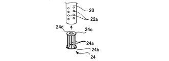
- the rotating cylinder 20 is made of, for example, a metal material such as stainless steel, and the ejection portion 22 including a plurality of ejection holes 22a is formed on the lower outer peripheral surface.
- the ejection holes 22a are formed at equal intervals along the circumferential direction so that the gas-liquid mixed liquid introduced into the rotary cylinder 20 from the introduction path 11a of the output shaft 11 is uniformly ejected toward the periphery.
- the ejection portions 22 are also formed at equal intervals in the axial direction so as to have a predetermined height (for example, about 150 mm).
- the diameter of the ejection hole 22a is not particularly limited, but is, for example, 0.1 to 1.5 mm. It is preferable that the outer peripheral surface of the rotating cylinder 20 is formed smoothly without providing a stirring blade or the like.
- a stirring member 24 is provided in the lower part inside the rotary cylinder 20.
- the stirring member 24 has a plurality of flat plate-like rotary blades 24 a arranged on a lower disk 24 b having a diameter substantially the same as the outer diameter of the rotary cylinder 20.
- a large number of rotor blades 24a are provided, it is preferable to arrange them radially at equal intervals.
- An upper disk 24c having a diameter substantially the same as the inner diameter of the rotary cylinder 20 is attached to the upper part of the rotary blade 24a. As shown by arrows in FIG.
- the stirring member 24 is inserted from below the rotary cylinder 20 so that the rotary blades 24a are positioned between the circumferentially adjacent ejection holes 22a, and the lower disk 24b rotates. It is fixed to the rotating cylinder 20 so as to close the lower opening of the cylinder 20.
- the upper disk 24c has a communication hole 24d formed at the center, and the gas-liquid mixed liquid introduced into the rotary cylinder 20 passes through the communication hole 24d and is stirred by the rotary blade 24a. Erupted.
- the shape and arrangement of the rotary blade 24a are not particularly limited as long as a swirl flow can be generated inside the rotary cylinder 20. For example, instead of the flat plate-like rotary blade 24a, a curved or spiral shape is used. Rotating blades such as airfoils may be used.
- the outer cylinder 30 is formed in a straight cylinder shape made of, for example, a resin such as acrylic or a metal such as stainless steel. 2 is fixed. The lower end of the outer cylinder 30 substantially coincides with the lower end of the inner cylinder 20, and the ejection portion 22 of the rotating cylinder 20 is covered with the outer cylinder 30.
- a spiral guide plate (not shown) may be provided on the inner peripheral surface of the outer cylinder 30 so that a swirling flow of the liquid L is likely to occur inside the outer cylinder 30.
- the circulation device 40 is connected to the discharge port 4 a formed at the bottom of the liquid storage tank 4 and the introduction part 14, and the liquid L in the liquid storage tank 4 is interposed between the pipe 42 and the liquid storage tank 4. And a circulation pump 44 to be taken out from the outside.
- the gas-liquid mixing unit 50 is disposed downstream of the circulation pump 44 in the middle of the pipe 42, and is pressurized and supplied from an air supply device 52 such as a compressor or a gas cylinder to the liquid L passing through the inside. Mix the gas.
- the configuration of the gas-liquid mixing unit 50 is not particularly limited, and for example, a pore blowing method in which bubbles are mixed into the liquid through the pores of the porous film, and gas and liquid are swirled at high speed to be mixed.
- a swirl flow system, a venturi system that introduces gas using a negative pressure generated by the passage of the liquid L, or the like may be used.
- the gas-liquid mixing unit 50 can suck the outside air and mix it with the liquid L without providing the air supply device 52.
- the gas-liquid mixture discharged from the gas-liquid mixing unit 50 is supplied into the liquid storage tank 4 from the ejection unit 22 of the rotary cylinder 20.
- the gas-liquid mixing unit 50 may be configured to include a liquid electrolysis device that generates bubbles by electrolyzing the liquid. In this configuration, the generated bubbles are separated from the liquid that has not been electrolyzed. You may supply in the piping 42 in the mixed state.
- the air supply device 52 may be used in combination, but energy saving can be achieved by a configuration in which the air supply device 52 is not provided.
- a branch pipe 53 is connected to the pipe 42 constituting the circulation path, and a part of the gas-liquid mixed liquid flowing through the pipe 42 is adjusted by adjusting the opening degree of the on-off valve 54 provided in the middle of the branch pipe 53. Can be continuously taken out from the branch pipe 53.
- the pipe 42 is configured to be able to supply the liquid L from the liquid supply device 55, and the liquid L corresponding to the amount discharged from the branch pipe 53 is continuously adjusted by adjusting the opening degree of the on-off valve 56. Can be replenished.
- the pipe 42 may be configured to include a magnetic processing unit that applies a magnetic field to the inside using a permanent magnet or the like, and the retention of fine bubbles can be improved by liquid magnetic processing.
- a liquid L such as water is stored in the storage tank 4, and substantially the entire rotating cylinder 20 is immersed in the liquid.
- the rotary cylinder 20 rotates around the axis together with the rotary blade 24a as shown by an arrow in FIG. 3, and is introduced into the rotary cylinder 20 from the circulation device 40.
- the gas-liquid mixture is swirled by the rotor blades 24a and ejected from the ejection section 22.
- the liquid level S of the liquid L becomes a mortar-shaped recess centered on the rotating cylinder 20, and the liquid level S reaches the vicinity of the ejection part 22 around the rotating cylinder 20. Decrease and move up and down around here. For this reason, the jet stream F of the gas-liquid mixture discharged from each ejection hole 22a is stirred while colliding with the liquid surface S and taken into the liquid, so that the bubbles become fine and diffuse into the liquid L.
- the rotational speed of the rotary cylinder 20 is adjusted so that the liquid level S is maintained in the vicinity of the ejection portion 22. It is preferable (for example, 3600 to 15000 revolutions per minute, or 15000 revolutions per minute or more).
- the gap generated between the rotary cylinder 20 and the outer cylinder 30 is preferably set as appropriate so that the desired liquid level S can be easily lowered, for example, 10 to 20 mm or 20 mm or more. It is.
- the gas-liquid mixed liquid ejected from the ejection part 22 by the rotation of the rotary cylinder 20 is mixed with the liquid L while performing liquid draining. Therefore, it is possible to efficiently generate a fine bubble mixed liquid in which fine bubbles such as microbubbles and nanobubbles are mixed.
- the rotary cylinder 20 is radially arranged so that the rotary blades 24 extend from the inner peripheral surface toward the center, the rotational resistance is increased as compared with the case where the rotary blades are provided on the outer peripheral surface of the rotary cylinder 20. Can be suppressed, and power saving can be achieved.
- the gas supplied to the gas-liquid mixing unit 50 may be oxygen, ozone, carbon dioxide, nitrogen, hydrogen, or the like, in addition to air. It can be retained in the liquid for a long time as bubbles.
- a fine bubble mixture containing oxygen as fine bubbles in water can be suitably used for sterilization and sterilization.
- the liquid L can be appropriately selected other than water depending on the application, and is preferably low temperature (for example, 10 ° C. or lower) in order to maintain fine bubbles for a long time.
- a heat exchanger for cooling is arranged along the outer periphery of the liquid storage tank 4 or so as to be immersed in the liquid L in the liquid storage tank 4. Also good.
- the outer cylinder 30 is arrange
- the outer cylinder 30 is not essential, for example, When the storage tank 4 has a small cylindrical shape, a configuration in which the outer cylinder 30 is not provided may be used.
- the gas / liquid mixed liquid is stably supplied from the ejection part 22 by forming the introduction path 11a for introducing the gas / liquid mixed liquid into the rotary cylinder 20 in the output shaft 11 of the drive motor 10.
- the introduction path 11a may be other than the output shaft 11, and is configured to introduce the gas-liquid mixture from the upper part or the side part of the rotary cylinder 20 via a mechanical seal or the like. Also good.
- the apparatus 1 for producing a fine bubble mixed solution may be configured to further include a support member 60 that rotatably supports the lower end portion of the rotary cylinder 20.
- the support member 60 includes a holding plate 62 at the lower end portion of the support cylinder 61, and a sliding bearing 63 is provided on the holding plate 62, and the distal end portion 20 a of the rotating cylinder 20 is supported by the sliding bearing 63.
- the support cylinder 61 is appropriately formed with a flow hole 61a through which the liquid L flows inside and outside. According to this configuration, the rotary cylinder 20 can be rotated more stably, and a desired fine bubble mixture can be easily generated.
- the rotary shaft 20 may be connected via a shaft coupling 71.
- a base plate 73 is provided on the upper surface of the support plate 2 via a plurality of support columns 72, and a through hole 73 a through which the output shaft 11 is inserted is formed in the base plate 73, thereby driving on the base plate 73.
- a casing 12 of the motor 10 can be mounted.
- a through-hole seal 74 through which the rotary shaft 20 is inserted in an airtight manner is provided in the through hole 2 a of the support plate 2.
Landscapes
- Chemical & Material Sciences (AREA)
- Chemical Kinetics & Catalysis (AREA)
- Mixers Of The Rotary Stirring Type (AREA)
Abstract
Description
4 貯液槽
6 気泡供給装置
10 駆動モータ
20 回転筒
22 噴出部
24a 回転翼
30 外筒
40 循環装置
50 気液混合部
60 支持部材
L 液体
Claims (4)
- 貯液槽と、前記貯液槽に貯留された液体に気泡を供給する気泡供給手段とを備え、
前記気泡供給手段は、外周面に噴出部を有し駆動手段により回転駆動される回転筒と、前記貯液槽に貯留された液体を取り出して前記噴出部から前記貯液槽に供給する循環手段と、前記循環手段により循環される液体に気泡を混合する気液混合部とを備えており、
前記貯液槽に貯留された液体に前記噴出部を浸漬させて前記回転筒を回転させることにより、気泡が混合された液体を前記噴出部から噴出させて、微細気泡混合液を生成する微細気泡混合液の製造装置。 - 前記回転筒は、内部に回転翼を備える請求項1に記載の気液混合装置。
- 前記回転筒の外周面との間に隙間をあけて同軸状に配置された外筒を更に備える請求項1または2に記載の気液混合装置。
- 貯液槽に貯留された液体に気泡を混合して微細気泡混合液を製造する方法であって、
外周面に噴出部を有する回転筒を垂下させて、前記噴出部を前記貯液槽の液中に浸漬させた状態で前記回転筒を回転させ、前記貯液槽の液体を取り出して気泡を混合した後に前記噴出部から噴出させることにより、微細気泡混合液を生成する微細気泡混合液の製造方法。
Priority Applications (3)
| Application Number | Priority Date | Filing Date | Title |
|---|---|---|---|
| US16/302,513 US10960365B2 (en) | 2016-05-24 | 2017-05-23 | Apparatus and method for producing fine air bubble mixed liquid |
| EP17802791.8A EP3444024B1 (en) | 2016-05-24 | 2017-05-23 | Apparatus and method for producing fine air bubble mixed liquid |
| JP2018519555A JP6797424B2 (ja) | 2016-05-24 | 2017-05-23 | 微細気泡混合液の製造装置および製造方法 |
Applications Claiming Priority (2)
| Application Number | Priority Date | Filing Date | Title |
|---|---|---|---|
| JP2016103475 | 2016-05-24 | ||
| JP2016-103475 | 2016-05-24 |
Publications (1)
| Publication Number | Publication Date |
|---|---|
| WO2017204205A1 true WO2017204205A1 (ja) | 2017-11-30 |
Family
ID=60411308
Family Applications (1)
| Application Number | Title | Priority Date | Filing Date |
|---|---|---|---|
| PCT/JP2017/019156 Ceased WO2017204205A1 (ja) | 2016-05-24 | 2017-05-23 | 微細気泡混合液の製造装置および製造方法 |
Country Status (4)
| Country | Link |
|---|---|
| US (1) | US10960365B2 (ja) |
| EP (1) | EP3444024B1 (ja) |
| JP (1) | JP6797424B2 (ja) |
| WO (1) | WO2017204205A1 (ja) |
Cited By (2)
| Publication number | Priority date | Publication date | Assignee | Title |
|---|---|---|---|---|
| JP2021079314A (ja) * | 2019-11-15 | 2021-05-27 | アクアインテック株式会社 | 気泡供給施設 |
| JP7511232B2 (ja) | 2020-10-13 | 2024-07-05 | 株式会社富喜製作所 | 気液撹拌装置 |
Families Citing this family (1)
| Publication number | Priority date | Publication date | Assignee | Title |
|---|---|---|---|---|
| WO2017204205A1 (ja) * | 2016-05-24 | 2017-11-30 | 日新技研株式会社 | 微細気泡混合液の製造装置および製造方法 |
Citations (2)
| Publication number | Priority date | Publication date | Assignee | Title |
|---|---|---|---|---|
| JP2001058195A (ja) * | 1995-12-28 | 2001-03-06 | Saburo Murakami | エアーチャージャー |
| JP2010162457A (ja) * | 2009-01-14 | 2010-07-29 | Lwj Kk | 微細気泡発生ノズル及び微細気泡発生装置 |
Family Cites Families (27)
| Publication number | Priority date | Publication date | Assignee | Title |
|---|---|---|---|---|
| US1031666A (en) * | 1912-04-01 | 1912-07-02 | Walter Richmond | Centrifugal emulsifier or mixer. |
| US3024011A (en) * | 1958-08-14 | 1962-03-06 | William D Wurdack | Centripetal disperser |
| US3415650A (en) * | 1964-11-25 | 1968-12-10 | Eastman Kodak Co | Method of making fine, uniform silver halide grains |
| US3785777A (en) * | 1971-11-01 | 1974-01-15 | Eastman Kodak Co | Apparatus for the uniform preparation of silver halide grains |
| US4889701A (en) * | 1982-01-04 | 1989-12-26 | Mobil Oil Corporation | Process for oxidizing multivalent metals |
| JPS59105825A (ja) * | 1982-12-10 | 1984-06-19 | Furukawa Mining Co Ltd | 液体混合装置 |
| US4515482A (en) * | 1983-08-11 | 1985-05-07 | The Upjohn Company | Sterile suspension and solution holding and mixing tank |
| JPS60102927A (ja) * | 1983-11-11 | 1985-06-07 | Atsushi Sakai | 流体撹拌混合装置 |
| GB2168904B (en) * | 1984-11-30 | 1988-01-27 | Ceskoslovenska Akademie Ved | Method of circulation of liquid phase through a solid phase particularly for biocatalytical reactions and a device for realization thereof |
| US4743428A (en) * | 1986-08-06 | 1988-05-10 | Cominco Ltd. | Method for agitating metals and producing alloys |
| JPS63224721A (ja) * | 1987-03-12 | 1988-09-19 | Mitsubishi Heavy Ind Ltd | 自吸式微細気泡発生装置 |
| US5087377A (en) * | 1987-08-03 | 1992-02-11 | Microlift Systems Limited Partnership | High pressure oxygen-saturated water-treatment |
| US4948262A (en) * | 1989-06-22 | 1990-08-14 | Tome Jr Floyd | Rotary mixing and straining apparatus |
| US5520818A (en) * | 1989-12-06 | 1996-05-28 | The University Of Toronto Innovations Foundation | Method for effecting gas-liquid contact |
| US5403088A (en) * | 1993-06-18 | 1995-04-04 | The Dow Chemical Company | Apparatus and method for the dispersion of minute bubbles in liquid materials for the production of polymer foams |
| US5660766A (en) * | 1995-09-22 | 1997-08-26 | Van Dyek; Bernhard | Aerator |
| EP0827940A4 (en) * | 1995-12-28 | 1999-09-22 | Sanki Co Ltd | AIR RENEWAL DEVICE |
| US5951921A (en) * | 1997-01-31 | 1999-09-14 | Core Corporation | Apparatus for producing ozone water |
| US6357725B2 (en) * | 1999-07-30 | 2002-03-19 | Shinnosuke Nomura | Gas/liquid mixing device |
| JP3318304B2 (ja) | 1999-07-30 | 2002-08-26 | 野村電子工業株式会社 | 気液混合装置 |
| US6857774B2 (en) * | 2002-08-02 | 2005-02-22 | Five Star Technologies, Inc. | Devices for cavitational mixing and pumping and methods of using same |
| WO2006041541A1 (en) * | 2004-10-07 | 2006-04-20 | Christopher White | A mixing system |
| DE102006045088A1 (de) * | 2006-09-21 | 2008-03-27 | Basf Ag | Verfahren zum Durchmischen einer in einem im wesentlichen abgeschlossenen Behälter befindlichen Flüssigkeit oder Mischung aus einer Flüssigkeit und einem feinteiligen Feststoff |
| WO2012159035A1 (en) * | 2011-05-19 | 2012-11-22 | Praxair Technology, Inc. | Systems and methods for dynamic gas control in a disposable vessel |
| FI124934B (fi) * | 2013-01-30 | 2015-03-31 | Outotec Oyj | Sekoitussäiliöreaktori |
| JP6027153B2 (ja) * | 2015-01-28 | 2016-11-16 | 日新技研株式会社 | 気液混合装置および微細気泡混合液の製造方法 |
| WO2017204205A1 (ja) * | 2016-05-24 | 2017-11-30 | 日新技研株式会社 | 微細気泡混合液の製造装置および製造方法 |
-
2017
- 2017-05-23 WO PCT/JP2017/019156 patent/WO2017204205A1/ja not_active Ceased
- 2017-05-23 JP JP2018519555A patent/JP6797424B2/ja active Active
- 2017-05-23 EP EP17802791.8A patent/EP3444024B1/en active Active
- 2017-05-23 US US16/302,513 patent/US10960365B2/en active Active
Patent Citations (2)
| Publication number | Priority date | Publication date | Assignee | Title |
|---|---|---|---|---|
| JP2001058195A (ja) * | 1995-12-28 | 2001-03-06 | Saburo Murakami | エアーチャージャー |
| JP2010162457A (ja) * | 2009-01-14 | 2010-07-29 | Lwj Kk | 微細気泡発生ノズル及び微細気泡発生装置 |
Cited By (3)
| Publication number | Priority date | Publication date | Assignee | Title |
|---|---|---|---|---|
| JP2021079314A (ja) * | 2019-11-15 | 2021-05-27 | アクアインテック株式会社 | 気泡供給施設 |
| JP7371902B2 (ja) | 2019-11-15 | 2023-10-31 | アクアインテック株式会社 | 気泡供給施設 |
| JP7511232B2 (ja) | 2020-10-13 | 2024-07-05 | 株式会社富喜製作所 | 気液撹拌装置 |
Also Published As
| Publication number | Publication date |
|---|---|
| JPWO2017204205A1 (ja) | 2019-03-28 |
| US10960365B2 (en) | 2021-03-30 |
| EP3444024A1 (en) | 2019-02-20 |
| US20190275477A1 (en) | 2019-09-12 |
| EP3444024B1 (en) | 2021-07-21 |
| JP6797424B2 (ja) | 2020-12-09 |
| EP3444024A4 (en) | 2019-12-11 |
Similar Documents
| Publication | Publication Date | Title |
|---|---|---|
| US7661658B2 (en) | Submersible hollow shaft motor and submersible floating aerator comprising the same | |
| JP6103517B2 (ja) | 貫流ポンプ極微細気泡流供給装置 | |
| CN106673223B (zh) | 基于湍动微气泡的曝气装置 | |
| JP4392540B1 (ja) | 微細気泡分散水の製造装置 | |
| US7661659B2 (en) | Swing-type submersible floating aerator | |
| JP6027153B2 (ja) | 気液混合装置および微細気泡混合液の製造方法 | |
| JP2024514214A (ja) | 微細気泡の発生方法および発生装置 | |
| WO2017204205A1 (ja) | 微細気泡混合液の製造装置および製造方法 | |
| JP2007136255A (ja) | ナノバブル発生装置 | |
| JP2000317488A (ja) | 水中曝気撹拌装置 | |
| JP6345545B2 (ja) | 曝気撹拌装置 | |
| JP2001276878A (ja) | 水中曝気撹拌装置 | |
| JP2010264337A (ja) | 曝気攪拌機 | |
| WO2012081632A1 (ja) | 曝気撹拌装置 | |
| JP2009247927A (ja) | 曝気攪拌機 | |
| KR101596639B1 (ko) | 미세 기포 발생장치 | |
| JP6345546B2 (ja) | 省動力型曝気撹拌装置 | |
| JP2005144320A (ja) | 流体混合装置 | |
| JPH05253592A (ja) | 攪拌曝気装置 | |
| JP2001104764A (ja) | 気液混合装置 | |
| JP2013063362A (ja) | 攪拌槽 | |
| JP2018020305A (ja) | 気体分離装置及びこれを利用した気体溶解装置 | |
| KR20090087371A (ko) | 산소 용해 장치 | |
| JP2000189774A (ja) | 気体溶解装置 | |
| JP2003211180A (ja) | 水中微小空気発生機 |
Legal Events
| Date | Code | Title | Description |
|---|---|---|---|
| ENP | Entry into the national phase |
Ref document number: 2018519555 Country of ref document: JP Kind code of ref document: A |
|
| WWE | Wipo information: entry into national phase |
Ref document number: 2017802791 Country of ref document: EP |
|
| ENP | Entry into the national phase |
Ref document number: 2017802791 Country of ref document: EP Effective date: 20181116 |
|
| NENP | Non-entry into the national phase |
Ref country code: DE |
|
| 121 | Ep: the epo has been informed by wipo that ep was designated in this application |
Ref document number: 17802791 Country of ref document: EP Kind code of ref document: A1 |