WO2017204234A1 - Frein à tambour de véhicule - Google Patents
Frein à tambour de véhicule Download PDFInfo
- Publication number
- WO2017204234A1 WO2017204234A1 PCT/JP2017/019289 JP2017019289W WO2017204234A1 WO 2017204234 A1 WO2017204234 A1 WO 2017204234A1 JP 2017019289 W JP2017019289 W JP 2017019289W WO 2017204234 A1 WO2017204234 A1 WO 2017204234A1
- Authority
- WO
- WIPO (PCT)
- Prior art keywords
- parking lever
- brake
- parking
- hole
- lever
- Prior art date
- Legal status (The legal status is an assumption and is not a legal conclusion. Google has not performed a legal analysis and makes no representation as to the accuracy of the status listed.)
- Ceased
Links
Images



Classifications
-
- F—MECHANICAL ENGINEERING; LIGHTING; HEATING; WEAPONS; BLASTING
- F16—ENGINEERING ELEMENTS AND UNITS; GENERAL MEASURES FOR PRODUCING AND MAINTAINING EFFECTIVE FUNCTIONING OF MACHINES OR INSTALLATIONS; THERMAL INSULATION IN GENERAL
- F16D—COUPLINGS FOR TRANSMITTING ROTATION; CLUTCHES; BRAKES
- F16D65/00—Parts or details
- F16D65/14—Actuating mechanisms for brakes; Means for initiating operation at a predetermined position
- F16D65/16—Actuating mechanisms for brakes; Means for initiating operation at a predetermined position arranged in or on the brake
- F16D65/22—Actuating mechanisms for brakes; Means for initiating operation at a predetermined position arranged in or on the brake adapted for pressing members apart, e.g. for drum brakes
-
- F—MECHANICAL ENGINEERING; LIGHTING; HEATING; WEAPONS; BLASTING
- F16—ENGINEERING ELEMENTS AND UNITS; GENERAL MEASURES FOR PRODUCING AND MAINTAINING EFFECTIVE FUNCTIONING OF MACHINES OR INSTALLATIONS; THERMAL INSULATION IN GENERAL
- F16D—COUPLINGS FOR TRANSMITTING ROTATION; CLUTCHES; BRAKES
- F16D51/00—Brakes with outwardly-movable braking members co-operating with the inner surface of a drum or the like
- F16D51/16—Brakes with outwardly-movable braking members co-operating with the inner surface of a drum or the like shaped as brake-shoes pivoted on a fixed or nearly-fixed axis
- F16D51/18—Brakes with outwardly-movable braking members co-operating with the inner surface of a drum or the like shaped as brake-shoes pivoted on a fixed or nearly-fixed axis with two brake-shoes
- F16D51/20—Brakes with outwardly-movable braking members co-operating with the inner surface of a drum or the like shaped as brake-shoes pivoted on a fixed or nearly-fixed axis with two brake-shoes extending in opposite directions from their pivots
-
- F—MECHANICAL ENGINEERING; LIGHTING; HEATING; WEAPONS; BLASTING
- F16—ENGINEERING ELEMENTS AND UNITS; GENERAL MEASURES FOR PRODUCING AND MAINTAINING EFFECTIVE FUNCTIONING OF MACHINES OR INSTALLATIONS; THERMAL INSULATION IN GENERAL
- F16D—COUPLINGS FOR TRANSMITTING ROTATION; CLUTCHES; BRAKES
- F16D51/00—Brakes with outwardly-movable braking members co-operating with the inner surface of a drum or the like
- F16D51/16—Brakes with outwardly-movable braking members co-operating with the inner surface of a drum or the like shaped as brake-shoes pivoted on a fixed or nearly-fixed axis
- F16D51/18—Brakes with outwardly-movable braking members co-operating with the inner surface of a drum or the like shaped as brake-shoes pivoted on a fixed or nearly-fixed axis with two brake-shoes
- F16D51/20—Brakes with outwardly-movable braking members co-operating with the inner surface of a drum or the like shaped as brake-shoes pivoted on a fixed or nearly-fixed axis with two brake-shoes extending in opposite directions from their pivots
- F16D51/22—Brakes with outwardly-movable braking members co-operating with the inner surface of a drum or the like shaped as brake-shoes pivoted on a fixed or nearly-fixed axis with two brake-shoes extending in opposite directions from their pivots mechanically actuated
-
- F—MECHANICAL ENGINEERING; LIGHTING; HEATING; WEAPONS; BLASTING
- F16—ENGINEERING ELEMENTS AND UNITS; GENERAL MEASURES FOR PRODUCING AND MAINTAINING EFFECTIVE FUNCTIONING OF MACHINES OR INSTALLATIONS; THERMAL INSULATION IN GENERAL
- F16D—COUPLINGS FOR TRANSMITTING ROTATION; CLUTCHES; BRAKES
- F16D65/00—Parts or details
- F16D65/02—Braking members; Mounting thereof
- F16D65/04—Bands, shoes or pads; Pivots or supporting members therefor
- F16D65/08—Bands, shoes or pads; Pivots or supporting members therefor for internally-engaging brakes
-
- F—MECHANICAL ENGINEERING; LIGHTING; HEATING; WEAPONS; BLASTING
- F16—ENGINEERING ELEMENTS AND UNITS; GENERAL MEASURES FOR PRODUCING AND MAINTAINING EFFECTIVE FUNCTIONING OF MACHINES OR INSTALLATIONS; THERMAL INSULATION IN GENERAL
- F16D—COUPLINGS FOR TRANSMITTING ROTATION; CLUTCHES; BRAKES
- F16D65/00—Parts or details
- F16D65/02—Braking members; Mounting thereof
- F16D65/04—Bands, shoes or pads; Pivots or supporting members therefor
- F16D65/08—Bands, shoes or pads; Pivots or supporting members therefor for internally-engaging brakes
- F16D65/09—Pivots or supporting members therefor
-
- F—MECHANICAL ENGINEERING; LIGHTING; HEATING; WEAPONS; BLASTING
- F16—ENGINEERING ELEMENTS AND UNITS; GENERAL MEASURES FOR PRODUCING AND MAINTAINING EFFECTIVE FUNCTIONING OF MACHINES OR INSTALLATIONS; THERMAL INSULATION IN GENERAL
- F16D—COUPLINGS FOR TRANSMITTING ROTATION; CLUTCHES; BRAKES
- F16D2121/00—Type of actuator operation force
- F16D2121/02—Fluid pressure
- F16D2121/04—Fluid pressure acting on a piston-type actuator, e.g. for liquid pressure
-
- F—MECHANICAL ENGINEERING; LIGHTING; HEATING; WEAPONS; BLASTING
- F16—ENGINEERING ELEMENTS AND UNITS; GENERAL MEASURES FOR PRODUCING AND MAINTAINING EFFECTIVE FUNCTIONING OF MACHINES OR INSTALLATIONS; THERMAL INSULATION IN GENERAL
- F16D—COUPLINGS FOR TRANSMITTING ROTATION; CLUTCHES; BRAKES
- F16D2121/00—Type of actuator operation force
- F16D2121/14—Mechanical
-
- F—MECHANICAL ENGINEERING; LIGHTING; HEATING; WEAPONS; BLASTING
- F16—ENGINEERING ELEMENTS AND UNITS; GENERAL MEASURES FOR PRODUCING AND MAINTAINING EFFECTIVE FUNCTIONING OF MACHINES OR INSTALLATIONS; THERMAL INSULATION IN GENERAL
- F16D—COUPLINGS FOR TRANSMITTING ROTATION; CLUTCHES; BRAKES
- F16D2125/00—Components of actuators
- F16D2125/18—Mechanical mechanisms
- F16D2125/58—Mechanical mechanisms transmitting linear movement
- F16D2125/64—Levers
-
- F—MECHANICAL ENGINEERING; LIGHTING; HEATING; WEAPONS; BLASTING
- F16—ENGINEERING ELEMENTS AND UNITS; GENERAL MEASURES FOR PRODUCING AND MAINTAINING EFFECTIVE FUNCTIONING OF MACHINES OR INSTALLATIONS; THERMAL INSULATION IN GENERAL
- F16D—COUPLINGS FOR TRANSMITTING ROTATION; CLUTCHES; BRAKES
- F16D65/00—Parts or details
- F16D65/38—Slack adjusters
- F16D65/40—Slack adjusters mechanical
- F16D65/52—Slack adjusters mechanical self-acting in one direction for adjusting excessive play
- F16D65/56—Slack adjusters mechanical self-acting in one direction for adjusting excessive play with screw-thread and nut
- F16D65/561—Slack adjusters mechanical self-acting in one direction for adjusting excessive play with screw-thread and nut for mounting within the confines of a drum brake
- F16D65/563—Slack adjusters mechanical self-acting in one direction for adjusting excessive play with screw-thread and nut for mounting within the confines of a drum brake arranged adjacent to service brake actuator, e.g. on parking brake lever, and not subjected to service brake force
Definitions
- the present invention relates to a vehicular drum brake, and more particularly to a vehicular drum brake having a parking lever that extends a brake shoe via a strut when the parking brake is operated.
- A a pair of brake shoes disposed on the backing plate so as to be expandable; and (b) a predetermined position located at one end of the one brake shoe in a state of being overlapped with one backing plate side of the pair of brake shoes.
- a first parking lever that is pivotable about the mounting shaft of the motor, and (c) a member different from the first parking lever, on the opposite side of the backing plate side with respect to one of the pair of brake shoes (D) a second parking lever provided to be rotatable about an attachment shaft in a state of being overlapped with one of the pair of brake shoes and the first parking lever, coupled to the first parking lever and rotated together; And a strut having a first strut member engaged with the first parking lever and the second parking lever.
- the vehicular drum brake described in Patent Document 1 is this.
- the parking lever is bent into a U-shaped cross section, and engages with the strut on both sides of one shoe web of the pair of brake shoes. Be made. This suppresses a biased load from acting on the other brake shoe during braking by the parking lever, thereby preventing the posture change or lifting of the brake shoe.
- the parking lever is bent into a U-shaped cross section so as to be located on both sides of the brake shoe, and the bent portion is linearly formed by bending,
- the shape of the parking lever increases by the amount of the bent part.
- it may be difficult to secure a gap in the vehicle drum brake for mounting a bearing of a vehicle axle tube.
- the parking lever since it is necessary for the parking lever to have a thin plate thickness so as to be suitable for bending, it may be difficult to ensure the strength of the parking lever.
- the present invention has been made against the background of the above circumstances, and the object of the present invention is for a vehicle using a parking lever that is downsized and has sufficient strength even when the plate thickness is reduced. To provide a drum brake.
- the gist of the first invention is that (a) a pair of brake shoes disposed on the backing plate so as to be spreadable, and (b) one of the pair of brake shoes overlapping the backing plate side, A first parking lever provided at one end of one of the brake shoes so as to be rotatable around a predetermined mounting shaft; and (c) the first parking lever is formed of a separate member, and the pair of brakes The first parking lever is provided so as to be rotatable about the mounting shaft in a state where it overlaps with one of the pair of brake shoes and the first parking lever on the side opposite to the backing plate side with respect to one of the shoes. A second parking lever that rotates together with the second parking lever; and (d) engages with the first parking lever and the second parking lever.
- a drum brake for a vehicle comprising: a strut having a first strut member; and (e) the first parking lever and the second parking lever are connected by a connecting pin so as to be simultaneously engaged with the first strut member. It is connected to each other.
- an axle through hole through which an axle is inserted is formed at a center portion of the backing plate, and the second parking lever is located on an end portion side away from the mounting shaft.
- a connecting hole, and is connected to the first parking lever via the connecting pin fitted into the connecting hole, and the connecting pin is The distance from the center line of the backing plate in the direction orthogonal to the center line of the axle through hole and the center axis of the strut is further away from the mounting shaft.
- an axle through hole through which an axle is inserted is formed at a center portion of the backing plate, and a latching hole formed in the first parking lever and the pair of brake shoes
- a lever return spring that is latched at both ends and biases the first parking lever toward the side away from the axle through hole. It exists in arrange
- the first parking lever and the second parking lever are arranged in a direction parallel to the central axis of the strut and symmetrical with respect to the central axis. Is to engage.
- the vehicular drum brake includes the first parking lever and the second parking lever, which is a member different from the first parking lever and is connected to the first parking lever and rotates together. And a parking lever.
- the first parking lever and the second parking lever are connected to each other by the connecting pin so as to simultaneously engage the first strut member on both sides of one shoe web of the pair of brake shoes.
- the first parking lever and the second parking lever can be integrated without forming a bent portion, for example, so that the shapes of the first parking lever and the second parking lever are reduced in size.
- the plate thickness is not limited by bending, so that the strength is ensured.
- the axle through hole through which the axle is inserted is formed at the center of the backing plate, and the second parking lever is connected to the connecting hole on the end side away from the mounting shaft. And is connected to the first parking lever via the connecting pin fitted in the connecting hole, and the connecting pin is connected to the axle through hole when a parking brake is not operated. And a distance from the center line of the backing plate in a direction orthogonal to the center axis of the strut is formed so as to be farther from the mounting shaft. Accordingly, the shapes of the first parking lever and the second parking lever are further reduced, and a sufficient clearance for mounting, for example, an axle bearing in the vehicle drum brake can be ensured more reliably. .
- an axle through hole through which an axle is inserted is formed at the center of the backing plate, and one of the latching hole formed in the first parking lever and the pair of brake shoes.
- a lever return spring is provided between the formed notch and both ends are latched to urge the first parking lever toward the side away from the axle through hole, and the connecting pin is connected to the mounting shaft. Is formed so as to be disposed on a side farther from the axle through hole than a straight line connecting the center of the latch hole and the center of the retaining hole. Accordingly, the shapes of the first parking lever and the second parking lever are further reduced, and a sufficient clearance for mounting, for example, an axle bearing in the vehicle drum brake can be ensured more reliably. .
- the first parking lever and the second parking lever are engaged with the first strut member in a direction parallel to the central axis of the strut and symmetrical with respect to the central axis. Is done.
- the first parking lever and the second parking lever are simultaneously moved on both sides of one shoe web of the pair of brake shoes. It becomes easy to apply a load evenly to one strut member. Therefore, the first parking lever and the second parking lever can more suitably suppress the application of an offset load to the other of the pair of brake shoes.
- FIG. 4 is an enlarged view showing a main part of an automatic shoe clearance adjusting device provided in the vehicle drum brake of FIG. 1, corresponding to a sectional view taken along line IV-IV of FIG.
- FIG. 4 is a diagram illustrating movement of a parking lever when a parking brake is operated in a vehicle drum brake to which the present invention is applied.
- It is a front view which shows the conventional drum brake for vehicles. In the conventional drum brake for vehicles, it is a figure showing movement of a parking lever when a parking brake is operated.
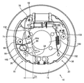
- FIG. 1 is a front view showing an example of a vehicle drum brake 10 to which the present invention is applied, and shows a leading trailing type vehicle drum brake 10.
- the vehicle drum brake 10 includes a disk-shaped backing plate 16 that is integrally fixed to a non-rotating member such as a vehicle axle tube, axle housing, suspension device, or the like (not shown).
- a range surrounded by a one-dot chain line shown in FIG. 1 indicates a space in which a bearing of a vehicle axle tube can be mounted, for example.
- An axle through hole 100 through which the axle is inserted is formed at the center of the backing plate 16.
- the center line of the axle through hole 100 is indicated by a center line C3.
- the vehicular drum brake 10 is disposed substantially symmetrically with respect to the center line C2 of the backing plate 16 so as to be able to approach and separate from each other with the arcuate convex side facing outward on the left and right outer peripheral portions of the backing plate 16. And a pair of brake shoes 18 and 20 provided on the backing plate 16 so as to be expandable. Further, the vehicle drum brake 10 includes a wheel cylinder 26 disposed between one end portions of the pair of brake shoes 18 and 20, that is, between the upper end portions in FIG. 1, and the other end portion of the pair of brake shoes 18 and 20. That is, the anchor 22 provided between the lower end portions in FIG.
- the center line C2 is a line passing through the center of the wheel cylinder 26 in the longitudinal direction, the center of the anchor 22 in the longitudinal direction, and the center of the backing plate 16 in the front view of FIG.
- Each of the brake shoes 18 and 20 has a flat plate shape substantially parallel to the plate surface of the backing plate 16, and the shoe webs 28 and 30 that are entirely curved in an arc shape in the front view shown in FIG.
- Arc-shaped shoe rims 32, 34 integrally fixed so that the cross-sections of the brake shoes 18, 20 form a substantially T-shape along the outer peripheral side edges of the shoe webs 28, 30 having the arc shape
- the shoe rims 32 and 34 are respectively provided with linings 36 and 38 made of a friction material fixed integrally to the outer peripheral surface of the shoe rims 32 and 34 with an adhesive or the like.
- the brake shoes 18 and 20 are pressed toward the backing plate 16 by shoe hold-down devices 42 and 44 disposed near the center in the longitudinal direction of the shoe webs 28 and 30, and the backing plate 16 can be expanded. It is arranged.
- the base end portion of the flat plate-like first parking lever 60 can be rotated around the mounting shaft 62 by the mounting shaft 62 in a state where a part of the one end portion of the brake shoe 18 overlaps the backing plate 16 side in a front view. It is connected to. Further, the one end portion of the brake shoe 18 is made of a member different from the first parking lever 60, and is opposite to the first parking lever 60 side with respect to the brake shoe 18 in the front view, that is, the backing plate 16.
- the base end portion of the flat plate-like second parking lever 70 is connected to the mounting shaft 62 so as to be rotatable around the mounting shaft 62 in a state where a part of the second parking lever 70 is overlapped with the side opposite to the front side.
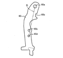
- FIG. 2 is an enlarged view of the first parking lever 60
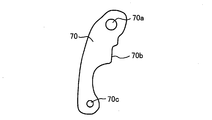
- FIG. 3 is an enlarged view of the second parking lever 70
- the first parking lever 60 is formed of a long flat plate having a gentle arc shape, and a mounting shaft hole 60a for fitting the mounting shaft 62 is formed at the base end portion.
- a first parking lever engaging portion 60b is formed linearly in the longitudinal direction on the base end side from the vicinity of the center in the longitudinal direction, and the first parking lever engaging portion 60b is formed. Is engaged with a first engaging portion 54a formed on a first strut member 54 described later.
- a connection hole (first connection hole) 60c is formed near the center in the longitudinal direction of the first parking lever 60.
- the first connecting hole 60 c is fitted with the connecting pin 71 by press-fitting a connecting member for connecting the first parking lever 60 with the second parking lever 70, for example, a connecting pin 71. Accordingly, the first parking lever 60 is formed integrally with the second parking lever 70.
- the first parking lever 60 has one lever return spring 64 stretched between the brake shoe 18 and the first parking lever 60 at a position farther from the base end than the first connecting hole 60c.
- a retaining hole 60d for retaining the end portion is formed.
- tip part of the 1st parking lever 60 which is an edge part on the opposite side spaced apart from the base end part is connected with the parking brake cable which is not shown in figure.
- the first connecting hole 60c is separated from the axle through hole 100 rather than the straight line D connecting the center of the mounting shaft hole 60a and the center of the latching hole 60d. It is formed so as to be disposed on the side, that is, on the brake shoe 18 side. Further, the first connecting hole 60c has a distance from the center line C3 of the axle through hole 100 and the center line C2 of the backing plate in the direction perpendicular to the center axis C1 of the strut 52 described later, which is larger than the mounting shaft hole 60a. Is formed to be.
- the vehicle drum brake 10 shown in FIG. 1 is in a state in which no operating force is applied to the tip of the first parking lever 60 via the parking brake cable by operating a parking brake lever (not shown), that is, the parking brake is activated. Indicates no state.
- the second parking lever 70 is formed of a long flat plate having a gentle arc shape, and is formed to be about half the length of the first parking lever 60.
- a mounting shaft hole 70 a into which the mounting shaft 62 is fitted is formed at the base end portion of the second parking lever 70. Therefore, the second parking lever 70 is connected to the brake shoe 18 and the first parking lever 60 via the mounting shaft 62, and the second parking lever 70 is connected to the first parking lever 60 when the first parking lever 60 is rotated. It is integrally rotated around the mounting shaft 62.
- a second parking lever engaging portion 70b is formed linearly in the longitudinal direction, and the second parking lever engaging portion 70b is a first strut described later.
- the first engaging portion 54a formed on the member 54 is engaged.
- the second parking lever engaging portion 70b and the first parking lever engaging portion 60b are positioned so as to overlap in front view and engage with the first engaging portion 54a. In some cases, they are formed to engage simultaneously.
- a connecting hole (second connecting hole) 70c is formed at the distal end portion of the second parking lever 70, which is the opposite end portion away from the base end portion.
- the second connecting hole 70 c is fitted with the connecting pin 71 by press-fitting a connecting pin 71 for connecting the second parking lever 70 to the first parking lever 60. Therefore, the second parking lever 70 is connected to the first parking lever 60 via the connecting pin 71.
- the first parking lever 60 and the second parking lever 70 are connected via an attachment shaft 62 and a connection pin 71, and the first parking lever 60 is adjusted by adjusting the lengths of the attachment shaft 62 and the connection pin 71.
- the second parking lever 70 can secure a predetermined gap.
- the gap between the first parking lever 60 and the second parking lever 70 is adjusted by adjusting the mounting shaft 62 and the connecting pin 71 so that the brake shoe is interposed between the first parking lever 60 and the second parking lever 70.
- the first parking lever 60 and the second parking lever 70 are formed in parallel with each other.
- the vehicular drum brake 10 has a pair of brake shoes 18, 20 between the one end portions thereof, that is, between the end portions on the wheel cylinder 26 side, between the brake shoes 18, 20 and the rotating drum.
- An automatic shoe gap adjusting device 76 that automatically adjusts the size of the shoe gap is bridged.
- FIG. 4 is an enlarged view of a main part of the shoe gap automatic adjusting device 76, and is a sectional view taken along line IV-IV in FIG.
- the shoe gap automatic adjusting device 76 is provided with a strut 52 so as to pass through the inside of a return spring 48 wound in a coil shape. When not operating, the standby position of the pair of brake shoes 18 and 20 is determined by the biasing force of the return spring 48.
- the strut 52 is engaged with a longitudinal first strut member 54 having a first engaging portion 54 a that engages with the first parking lever 60 and the second parking lever 70, and one end portion of the shoe web 30 of the brake shoe 20.
- a longitudinal second strut member 56 having a mating second engaging portion 56a is provided.
- the strut 52 is disposed between the first strut member 54 and the second strut member 56 by being disposed between the first strut member 54 and the second strut member 56 and being rotated about the central axis C1.
- An adjusting shaft 58 for extending the distance is provided.
- the central axis C1 is the central axis of the strut 52, and the first strut member 54 and the second strut member 56 are disposed concentrically with the central axis C1.
- the first parking lever 60 and the second parking lever 70 are engaged with the first engagement portion 54a in a direction parallel to the central axis C1 of the strut 52 and at a symmetrical position with respect to the central axis C1.
- the first engaging portion 54a is formed so as to be orthogonal to the central axis C1
- the first engaging portion 54a is formed linearly on the base end side of the first parking lever 60.
- the first parking lever engaging portion 60 b and the second parking lever engaging portion 70 b formed linearly on the base end side of the second parking lever 70 are adjusted by the mounting shaft 62 and the connecting pin 71. They are simultaneously engaged in a direction parallel to the central axis C1 and at a symmetrical position with respect to the central axis C1.
- the adjustment shaft 58 has a substantially disc-shaped adjustment wheel 58 a and a substantially cylindrical shape protruding from the rotation center of the adjustment wheel 58 a toward the second strut member 56 side.
- the adjustment wheel 58a is formed to have a diameter larger than the diameter of the screw shaft portion 58b, the diameter of the fitting shaft portion 58c, the outer diameter of the first strut member 54, and the outer diameter of the second strut member 56.
- the outer peripheral teeth (not shown) are formed on the adjustment wheel 58a, and the adjustment lever 90 is engaged with the outer peripheral teeth.
- the adjustment lever 90 is disposed on the backing plate 16 side of the brake shoe 20 and on the one end side of the brake shoe 20, and is connected to the brake shoe 20 by an adjustment lever mounting shaft 92.
- the adjusting lever 90 is rotated around the adjusting lever mounting shaft 92 by the adjusting lever mounting shaft 92.
- the strut 52 is a screw between a male screw formed on the screw shaft portion 58b and a female screw formed on the second strut member 56.
- the second strut member 56 is moved away from the first strut member 54, for example.
- the distance between the first engaging portion 54a and the second engaging portion 56a, that is, the longitudinal distance of the strut 52 is extended. To do.
- FIG. 5 is a diagram showing the movement of the parking lever when the parking brake is operated in the vehicle drum brake 10 to which the present invention is applied.
- an operating force is applied to the tip of the first parking lever 60 in the direction of the arrow shown in FIG. 5 and the parking brake is activated, the tip of the first parking lever 60 is rotated around the mounting shaft 62. .
- an operation force in the direction of the arrow is applied to the tip of the first parking lever 60 via the parking brake cable by operating a parking brake lever (not shown), and the parking brake is activated.
- an operating force in the direction of the arrow is applied to the distal end portion of the first parking lever 60, the distal end portion of the first parking lever 60 is rotated around the attachment shaft 62 toward the center side of the backing plate 16.
- the brake shoe 20 When the front end portion of the first parking lever 60 is rotated, the brake shoe 20 is pushed by the strut 52 spanned between the one end portion of the brake shoe 18 and the one end portion of the brake shoe 20 so that the brake shoe 20 is on the outer peripheral side. At the same time, the brake shoe 18 is pushed by the mounting shaft 62 and moved to the outer peripheral side, so that the pair of brake shoes 18 and 20 are expanded, and the linings 36 and 38 become the inner periphery of the rotating drum (not shown). A braking force can be generated by surface contact with the surface.
- the lever return spring 64 having one end hooked to the first parking lever 60 is hooked to a notch 68 provided near the center in the longitudinal direction of the brake shoe 18 at the other end. That is, the lever return spring 64 is stretched between the brake shoe 18 and the first parking lever 60.
- the first parking lever 60 is separated from the axle through hole 100 by the biasing force of the lever return spring 64. It is made to contact.
- the movable distance D1 of the first parking lever 60 is within a range where the first parking lever 60 and an axle tube (not shown) do not interfere, that is, as shown in FIG. The range does not interfere with 100.
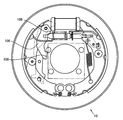
- FIG. 6 is a front view showing a conventional vehicle drum brake 10
- FIG. 7 is a diagram showing the movement of the parking lever 106 when the parking brake is operated in the conventional vehicle drum brake 10.
- FIG. A range surrounded by a one-dot chain line shown in FIG. 6 indicates a space in which, for example, a bearing of a vehicle axle tube can be mounted in the conventional vehicle drum brake 10.
- the parking lever 106 applied to the conventional vehicle drum brake 10 is bent so that one plate is bent into a U-shaped cross section, and the bent portion 108 is linearly formed by bending. . Since the parking lever 106 is formed with the bent portion 108 in a straight line, the shape of the parking lever 106 is increased. Therefore, the conventional vehicle drum brake 10 has a space in which the bearing of the axle tube can be mounted in FIG. It is smaller than the space in which the bearing of the axle tube of the drum brake 10 for a vehicle of this embodiment shown can be mounted.
- the distance D2 at which the parking lever 106 can move is within a range in which the parking lever 106 does not interfere with the axle through hole 100 when viewed from the front. Since the parking lever 106 is formed with a bent portion 108, the movable range of the parking lever 106 is smaller than the movable distance D1 of the first parking lever 60 of this embodiment shown in FIG. Yes.
- the vehicle drum brake 10 is composed of a member different from the first parking lever 60 and the first parking lever, and is connected to the first parking lever 60 to rotate together.
- a second parking lever 70 is provided.
- the first parking lever 60 and the second parking lever 70 are mutually connected by a connecting pin 71 so as to be simultaneously engaged with the first strut member 54 on both sides of the shoe web 28 of the brake shoe 18 of the pair of brake shoes 18, 20. It is connected to.
- the 1st parking lever 60 and the 2nd parking lever 70 can be integrated, for example, without forming a bending part, the shape of the 1st parking lever 60 and the 2nd parking lever 70 is reduced in size.
- the first parking lever 60 and the second parking lever 70 are formed by separate members, the plate thickness is not limited by bending, so that the strength is ensured.
- the shapes of the first parking lever 60 and the second parking lever 70 are reduced in size, a sufficient gap for mounting, for example, an axle bearing can be secured in the vehicle drum brake 10, and the first The distance that one parking lever 60 can be moved can be increased.
- the braking response of the vehicle drum brake 10 due to wear of parts related to braking of the parking brake such as the linings 36 and 38, the parking brake lever, and the parking brake cable can be coped with.
- the plate thickness is not limited by bending, for example, the vehicle drum brake 10 in which the first parking lever 60 and the second parking lever 70 having different plate thicknesses are selected can be dealt with.
- parts of the vehicle drum brake 10 of different vehicle types can be used, so that the parts can be easily shared.
- the parking brake is operated and braking is performed by the parking lever, the first parking lever 60 and the second parking lever 70 are simultaneously transferred to the first strut member 54 on both sides of the shoe web 28 of the brake shoe 18.
- the load can be applied evenly. For this reason, it is possible to suppress the uneven load from acting on the brake shoe 20.
- the axle through hole 100 through which the axle is inserted is formed at the center of the backing plate 16, and the second parking lever 70 is located on the end side away from the mounting shaft 62. It has the 2nd connecting hole 70c, and is connected with the 1st parking lever 60 via the connecting pin 71 fitted in the 2nd connecting hole 70c, and the parking brake is not operated.
- the distance from the center line C2 of the backing plate 16 in the direction orthogonal to the center line C3 of the axle through hole 100 and the center axis C1 of the strut 52 is formed to be farther from the mounting shaft 62.
- the shapes of the first parking lever 60 and the second parking lever 70 are further miniaturized, and a sufficient clearance for mounting, for example, axle bearings in the vehicle drum brake 10 can be more reliably secured. it can.
- the axle through hole 100 through which the axle is inserted is formed at the center of the backing plate 16, and the retaining hole 60 d formed in the first parking lever 60 and the pair of brake shoes. 18 and 20, a notch 68 formed in the brake shoe 18 is hooked at both ends to abut the first parking lever 60 away from the axle through hole 100, that is, the brake shoe 18.
- a lever return spring 64 is provided to be biased to the side to be moved, and the connecting pin 71 is located on the side farther from the axle through hole 100 than the straight line D connecting the center of the mounting shaft 62 and the center of the retaining hole 60d, that is, the brake shoe It is formed so as to be arranged on the 18th side.
- the shapes of the first parking lever 60 and the second parking lever 70 are further miniaturized, and a sufficient clearance for mounting, for example, axle bearings in the vehicle drum brake 10 can be more reliably secured. it can.
- the first parking lever 60 and the second parking lever 70 are arranged in a direction parallel to the central axis C1 of the strut 52 and symmetrical with respect to the central axis C1. Is engaged.
- the first parking lever 60 and the second parking lever 70 are simultaneously applied to the first strut member 54 on both sides of the shoe web 28 of the brake shoe 18.
- the load can be applied more evenly. Therefore, the first parking lever 60 and the second parking lever 70 can more suitably suppress the application of an offset load to the brake shoe 20.
- the connecting pin 71 is press-fitted into the first connecting hole 60c and the second connecting hole 70c and integrated.
- the present invention is not limited to this, and the connecting pin 71 is connected by caulking.
- the first connecting hole 60c and the second connecting hole 70c may be integrated.
Landscapes
- Engineering & Computer Science (AREA)
- General Engineering & Computer Science (AREA)
- Mechanical Engineering (AREA)
- Braking Arrangements (AREA)
Abstract
La présente invention propose un frein à tambour de véhicule utilisant des leviers de stationnement dont la taille est réduite et qui assurent une résistance suffisante même si leurs épaisseurs sont réduites. Il est prévu un premier levier de stationnement (60) et un second levier de stationnement (70) qui est raccordé au premier levier de stationnement (60) et qui tournent conjointement avec ce dernier. Le premier levier de stationnement (60) et le second levier de stationnement (70) sont engagés simultanément avec un premier élément de renfort (54) des deux côtés d'une nervure (28) d'un sabot de frein (18). Cela rend les formes du premier levier de stationnement (60) et du second levier de stationnement (70) compactes. En outre, étant donné que le premier levier de stationnement (60) et le second levier de stationnement (70) sont formés d'éléments séparés, la limitation d'épaisseur imposée par la flexion est supprimée et, par conséquent, la résistance est assurée.
Priority Applications (3)
| Application Number | Priority Date | Filing Date | Title |
|---|---|---|---|
| US16/304,428 US10830300B2 (en) | 2016-05-24 | 2017-05-23 | Vehicle drum brake |
| CN201780032033.6A CN109154345B (zh) | 2016-05-24 | 2017-05-23 | 车辆用鼓式制动器 |
| EP17802820.5A EP3467332B1 (fr) | 2016-05-24 | 2017-05-23 | Frein à tambour de véhicule |
Applications Claiming Priority (2)
| Application Number | Priority Date | Filing Date | Title |
|---|---|---|---|
| JP2016103781A JP6198889B1 (ja) | 2016-05-24 | 2016-05-24 | 車両用ドラムブレーキ |
| JP2016-103781 | 2016-05-24 |
Publications (1)
| Publication Number | Publication Date |
|---|---|
| WO2017204234A1 true WO2017204234A1 (fr) | 2017-11-30 |
Family
ID=59895732
Family Applications (1)
| Application Number | Title | Priority Date | Filing Date |
|---|---|---|---|
| PCT/JP2017/019289 Ceased WO2017204234A1 (fr) | 2016-05-24 | 2017-05-23 | Frein à tambour de véhicule |
Country Status (5)
| Country | Link |
|---|---|
| US (1) | US10830300B2 (fr) |
| EP (1) | EP3467332B1 (fr) |
| JP (1) | JP6198889B1 (fr) |
| CN (1) | CN109154345B (fr) |
| WO (1) | WO2017204234A1 (fr) |
Families Citing this family (2)
| Publication number | Priority date | Publication date | Assignee | Title |
|---|---|---|---|---|
| JP7229635B2 (ja) * | 2018-09-27 | 2023-02-28 | ダイハツ工業株式会社 | ドラムブレーキ構造 |
| DE102021212677B4 (de) | 2021-11-10 | 2023-09-07 | Hl Mando Corporation | Trommelbremssystem mit zwei Zugfedern |
Citations (3)
| Publication number | Priority date | Publication date | Assignee | Title |
|---|---|---|---|---|
| JPS62172830U (fr) * | 1986-04-23 | 1987-11-02 | ||
| JP2000055091A (ja) * | 1998-08-07 | 2000-02-22 | Nisshinbo Ind Inc | 機械式ドラムブレーキ装置 |
| JP2002168274A (ja) * | 2000-11-30 | 2002-06-14 | Hosei Brake Ind Ltd | ドラムブレーキ |
Family Cites Families (10)
| Publication number | Priority date | Publication date | Assignee | Title |
|---|---|---|---|---|
| US5322145A (en) * | 1989-08-29 | 1994-06-21 | Kelsey-Hayes Company | Drum brake operating mechanism |
| FR2697600B1 (fr) * | 1992-10-30 | 1994-12-02 | Bendix Europ Services Tech | Frein à tambour à actionnement mécanique. |
| US5538112A (en) * | 1994-10-11 | 1996-07-23 | Kelsey-Hayes Company | Parking and emergancy brake actuating lever for drum brake assembly |
| US5529149A (en) * | 1994-11-21 | 1996-06-25 | Alliedsignal Inc. | Drum-in-hat brake with reverse scissors actuator |
| US5720367A (en) * | 1995-08-23 | 1998-02-24 | Kelsey-Hayes Company | Parking and emergency brake operating mechanism for dual mode drum brake assemlby |
| JP4794723B2 (ja) * | 2000-07-17 | 2011-10-19 | 日清紡ホールディングス株式会社 | ブレーキケーブル接続装置 |
| GB0324571D0 (en) * | 2003-10-22 | 2003-11-26 | Automotive Prod Italia Sv Srl | Parking brakes |
| US10138966B2 (en) * | 2014-03-11 | 2018-11-27 | Nissin Kogyo Co., Ltd. | Vehicle brake apparatus |
| CN204284268U (zh) * | 2014-11-12 | 2015-04-22 | 北汽福田汽车股份有限公司 | 一种制动系统和车辆 |
| CN104533989B (zh) * | 2014-12-01 | 2017-01-04 | 奇瑞汽车股份有限公司 | 行车领从蹄驻车双向双领蹄式制动器 |
-
2016
- 2016-05-24 JP JP2016103781A patent/JP6198889B1/ja active Active
-
2017
- 2017-05-23 CN CN201780032033.6A patent/CN109154345B/zh active Active
- 2017-05-23 EP EP17802820.5A patent/EP3467332B1/fr active Active
- 2017-05-23 WO PCT/JP2017/019289 patent/WO2017204234A1/fr not_active Ceased
- 2017-05-23 US US16/304,428 patent/US10830300B2/en active Active
Patent Citations (3)
| Publication number | Priority date | Publication date | Assignee | Title |
|---|---|---|---|---|
| JPS62172830U (fr) * | 1986-04-23 | 1987-11-02 | ||
| JP2000055091A (ja) * | 1998-08-07 | 2000-02-22 | Nisshinbo Ind Inc | 機械式ドラムブレーキ装置 |
| JP2002168274A (ja) * | 2000-11-30 | 2002-06-14 | Hosei Brake Ind Ltd | ドラムブレーキ |
Also Published As
| Publication number | Publication date |
|---|---|
| EP3467332B1 (fr) | 2020-09-30 |
| EP3467332A9 (fr) | 2019-07-10 |
| CN109154345A (zh) | 2019-01-04 |
| JP2017211003A (ja) | 2017-11-30 |
| CN109154345B (zh) | 2020-03-27 |
| EP3467332A1 (fr) | 2019-04-10 |
| JP6198889B1 (ja) | 2017-09-20 |
| US10830300B2 (en) | 2020-11-10 |
| EP3467332A4 (fr) | 2019-11-13 |
| US20190293136A1 (en) | 2019-09-26 |
Similar Documents
| Publication | Publication Date | Title |
|---|---|---|
| US20240229878A1 (en) | Wheel brake arrangement | |
| JP6198889B1 (ja) | 車両用ドラムブレーキ | |
| KR20200024532A (ko) | 드럼 브레이크 | |
| JP2014109312A (ja) | ドラムブレーキ | |
| JP2000329167A (ja) | 車両用ドラムブレーキ | |
| JP6491543B2 (ja) | デュオサーボ型ドラムブレーキ | |
| JP2002147506A (ja) | シュー間隙自動調節機構付きドラムブレーキ | |
| JP2003065370A (ja) | 二重巻バンドブレーキ装置 | |
| JP2008281179A (ja) | シュー間隙自動調節機構を備えたドラムブレーキ | |
| JP5816470B2 (ja) | ドラムブレーキ | |
| JP4825117B2 (ja) | ドラムブレーキ | |
| KR102548143B1 (ko) | 드럼 브레이크 | |
| JP2012036959A (ja) | 車両用ドラムブレーキ | |
| JP6878184B2 (ja) | 車両用ドラムブレーキのシュー間隙自動調節装置 | |
| JP4918419B2 (ja) | シュー間隙自動調節機構を備えたドラムブレーキ | |
| JP2010223337A (ja) | 車両用リーディングトレーリング型ドラムブレーキ | |
| JP2019163827A (ja) | 車両用ドラムブレーキ | |
| JPH068831U (ja) | 車両用ドラムブレーキのパーキングレバー | |
| JP2018017384A (ja) | デュオサーボ式ドラムブレーキ | |
| JP2013155860A (ja) | ドラムブレーキ | |
| JP2005098322A (ja) | ドラムブレーキ装置 | |
| JP2007016920A (ja) | ドラムブレーキ | |
| JPH0527719Y2 (fr) | ||
| JP2011185441A (ja) | シュー間隙自動調節機構を備えたドラムブレーキ | |
| JP2017129176A (ja) | 車両用ドラムブレーキ |
Legal Events
| Date | Code | Title | Description |
|---|---|---|---|
| NENP | Non-entry into the national phase |
Ref country code: DE |
|
| 121 | Ep: the epo has been informed by wipo that ep was designated in this application |
Ref document number: 17802820 Country of ref document: EP Kind code of ref document: A1 |
|
| ENP | Entry into the national phase |
Ref document number: 2017802820 Country of ref document: EP Effective date: 20190102 |