WO2017204273A1 - Dispositif de mandrin - Google Patents
Dispositif de mandrin Download PDFInfo
- Publication number
- WO2017204273A1 WO2017204273A1 PCT/JP2017/019452 JP2017019452W WO2017204273A1 WO 2017204273 A1 WO2017204273 A1 WO 2017204273A1 JP 2017019452 W JP2017019452 W JP 2017019452W WO 2017204273 A1 WO2017204273 A1 WO 2017204273A1
- Authority
- WO
- WIPO (PCT)
- Prior art keywords
- plunger
- rotation axis
- workpiece
- chuck
- chuck body
- Prior art date
- Legal status (The legal status is an assumption and is not a legal conclusion. Google has not performed a legal analysis and makes no representation as to the accuracy of the status listed.)
- Ceased
Links
Images






Classifications
-
- B—PERFORMING OPERATIONS; TRANSPORTING
- B23—MACHINE TOOLS; METAL-WORKING NOT OTHERWISE PROVIDED FOR
- B23B—TURNING; BORING
- B23B31/00—Chucks; Expansion mandrels; Adaptations thereof for remote control
- B23B31/02—Chucks
- B23B31/10—Chucks characterised by the retaining or gripping devices or their immediate operating means
- B23B31/12—Chucks with simultaneously-acting jaws, whether or not also individually adjustable
- B23B31/16—Chucks with simultaneously-acting jaws, whether or not also individually adjustable moving radially
- B23B31/16233—Jaws movement actuated by oblique surfaces of a coaxial control rod
-
- Y—GENERAL TAGGING OF NEW TECHNOLOGICAL DEVELOPMENTS; GENERAL TAGGING OF CROSS-SECTIONAL TECHNOLOGIES SPANNING OVER SEVERAL SECTIONS OF THE IPC; TECHNICAL SUBJECTS COVERED BY FORMER USPC CROSS-REFERENCE ART COLLECTIONS [XRACs] AND DIGESTS
- Y10—TECHNICAL SUBJECTS COVERED BY FORMER USPC
- Y10T—TECHNICAL SUBJECTS COVERED BY FORMER US CLASSIFICATION
- Y10T279/00—Chucks or sockets
- Y10T279/19—Radially reciprocating jaws
Definitions
- the present invention relates to a chuck device used by being attached to a machine tool such as a lathe.
- a chuck device disclosed in Patent Document 1 includes a chuck body having an accommodation space therein, and the chuck body communicates with the accommodation space and is connected to the rotation axis of the chuck body.
- Three guide grooves extending linearly in a direction orthogonal to each other are formed at equal intervals around the rotation axis.
- a plunger is slidably accommodated along the rotation axis in the accommodation space, and gradually moves away from the rotation axis as it moves away from the guide groove at a position corresponding to the guide groove of the plunger.
- a slide hole that is inclined linearly is formed.
- a master jaw that is substantially T-shaped in a side view is inserted into a portion communicating with the accommodation space of each guide groove, and a cylindrical portion that is slidably fitted into the slide hole at one end of the master jaw.
- a block-shaped top jaw is attached to the other end of the master jaw. Then, when the plunger is slid to one side, the surface forming the slide holes of the plunger is in sliding contact with the outer peripheral surface of each columnar part and presses each columnar part to the rotation axis side, so that each master jaw When the top jaws grip the workpiece by moving along the rotation axis, and the plunger is slid to the other side, the surfaces forming the slide holes of the plunger are the outer peripheral surfaces of the cylindrical portions.
- the master jaws move along the guide grooves while being in sliding contact with each other, and the master jaws move along the guide grooves so that the top jaws grip the workpiece. The state is to be canceled.
- the present invention has been made in view of such a point, and an object of the present invention is to provide a chuck device having a high gripping accuracy in which the gripping position of the workpiece does not deviate from the reference position.
- the present invention performs positioning of the plunger with respect to the chuck body by utilizing an action in which the elastically deformed portion of the plunger generated when gripping the workpiece slides on the inner peripheral surface of the chuck body. It is characterized by doing so.
- a spindle that is driven to rotate, and is provided so as to be rotatable around the rotation axis, and has an accommodation space inside, communicates with the accommodation space, and is connected to the rotation axis.
- a plurality of guide portions extending in a direction orthogonal to each other are guided by the guide body and the guide portions at equal intervals around the rotation axis, and one end side is accommodated in the accommodation space and the other end is top.
- a plurality of master jaws to which jaws are attached, and a plurality of linkage means that are accommodated in the accommodation space and are slidable along the rotation axis, and are linked to one end side of each master jaw.
- Each of the linking means moves the master jaws along the guide portions by sliding movement of the plunger to one side.
- the top jaws grip the workpiece by approaching the rolling axis, while the linkage means causes the master jaws to move along the guide portions by the sliding movement of the plunger to the other side.
- the chuck device configured to release the gripping state of the workpiece by separating the top jaws from each other, the following solution is taken.
- the outer peripheral surface of the chuck body that is generated on the inner peripheral surface around the rotational axis of the chuck body at the portion corresponding to each linking means of the plunger by the gripping operation of the workpiece by the top jaws.
- An alignment portion that moves the plunger by sliding the deformed portion due to the elastic deformation operation along with the elastic deformation operation to match the linking means with a predetermined set position with respect to the guide portions. It is provided.
- a cross section that is away from the rotation axis and orthogonal to the rotation axis is curved.
- An overhanging portion is provided so as to extend, and the alignment portion has a concave cross section perpendicular to the rotational axis, and the overhanging portions are fitted with a small gap therebetween. It is characterized by being a some fitting recessed part.
- the inner peripheral surface of each of the fitting recesses has a curved shape having a first radius of curvature when viewed in the extending direction of the rotation axis.
- the projecting surface of the part has a curved shape having a second radius of curvature when viewed in the extending direction of the rotation axis, the first radius of curvature is ⁇ 1, and the second radius of curvature is ⁇ 2. , ⁇ 1 ⁇ ⁇ 2.
- the position of the plunger corresponding to each linkage means is a plurality of perpendicular to the straight line passing through the center of the linkage means and perpendicular to the rotation axis.
- a flat surface portion is provided, and the positioning portion has a flat shape perpendicular to the guide portion, and the flat surface portion is a plurality of sliding surface portions facing each other with a minute gap.
- each linking means when the workpiece is gripped by each top jaw, each linking means is moved to a predetermined set position with respect to each guide portion by the elastic deformation operation of the plunger. Therefore, the position of the plunger with respect to the chuck body does not vary when the workpiece gripping operation by each top jaw is completed, and the workpiece gripping position does not deviate from the reference position, so that the workpiece can be gripped with high accuracy.
- the thickness of the corresponding portion between the protruding portions of the plunger in the chuck body is increased, so that the rigidity of the chuck body is increased. Therefore, the chuck body is deformed during the gripping operation of the workpiece, and this causes each master jaw to tilt, or the position of each master jaw shifts and the gripping accuracy by each top jaw decreases. Can be prevented. In addition, since the rigidity of the chuck body is increased, vibrations are less likely to occur in the apparatus when the workpiece is processed, so that the chatter phenomenon in the workpiece can be prevented.
- the protruding surface of each of the protruding portions that curves is in sliding contact with the inner peripheral surface of each of the curved fitting recesses, so that the plunger moves relative to the chuck body.
- the operation becomes smooth and the positioning of the plunger with respect to the chuck body can be performed efficiently.
- the position where the plunger is aligned with respect to the chuck body is a flat shape, so that the machining of the chuck body and the plunger is easier than in the second invention, and the machining cost can be reduced. it can.
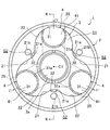
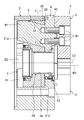
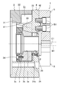
- FIG. 3 is a cross-sectional view taken along line III-III in FIG. 2.
- FIG. 4 is a view corresponding to FIG. 3 showing a state where a workpiece is gripped.
- FIG. 5 is a sectional view taken along line VV in FIG. 3.
- FIG. 6 is a cross-sectional view taken along line VI-VI in FIG. 4.
- FIG. 4 is a view corresponding to FIG. 3 according to Embodiment 2 of the present invention. It is the IX section enlarged view in FIG. FIG.
- FIG. 10 is a diagram illustrating a state where a workpiece is gripped after FIG. 9. It is a rear view of the chuck device concerning Embodiment 3 of the present invention. It is FIG. 3 equivalent view which concerns on Embodiment 3 of this invention. It is the XIII section enlarged view in FIG. It is a figure which shows the state which hold
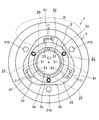
- FIG. 1 shows a chuck device 1 according to Embodiment 1 of the present invention.
- the chuck device 1 is for attaching a workpiece W1 (see FIGS. 3 and 4) to a machine tool such as a lathe, and has a disk shape that can rotate around the rotation axis C1 with a central axis as a rotation axis C1.
- the chuck body 2 is provided.
- a housing space S1 having a substantially three-leaf shape as viewed in the extending direction of the rotation axis C1 is formed inside the chuck body 2, and the extending direction of the rotation axis C1 in the housing space S1 is formed.
- One side is open.
- bulging portions 21 that bulge in a substantially mountain shape when viewed in the extending direction of the rotation axis C1 are arranged at regular intervals around the rotation axis C1.
- a concave groove 21a whose section perpendicular to the rotational axis C1 is gently curved extends straight along the rotational axis C1.
- a fixing hole 21b extending in the extending direction of the rotation axis C1 is formed in the center of the bulging portion 21, and the chuck device 1 is bolted to a spindle of a machine tool (not shown) using the fixing hole 21b. It can be fixed with.
- fitting recess 22 Positioning portion having a concave cross section perpendicular to the rotation axis C1. Three are formed.
- Each fitting recess 22 has a shape in which a cross section perpendicular to the rotational axis C1 is gently curved and extends straight along the rotational axis C1.
- each fitting recess 22 has a curved shape with a radius of curvature of ⁇ 1 (first radius of curvature) when viewed in the extending direction of the rotation axis C1. There is no.
- a through hole 23 having a circular cross section is formed in the center of the wall surface on the other side in the extension direction of the rotation axis C1 in the chuck body 2. As shown in FIG.
- the cylindrical member 24 is fitted into the through hole 23, and approximately half of the cylindrical member 24 in the cylinder center line direction faces the accommodation space S1.
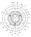
- guide grooves 25 (guide portions) having a substantially T-shaped cross section and extending in a direction orthogonal to the rotation axis C1 are arranged at equal intervals around the rotation axis C1. Each guide groove 25 communicates with the accommodation space S1.
- a substantially three-leaf shaped plunger 3 corresponding to the shape of the accommodation space S1 is accommodated.
- a fitting hole 3a extending in the extending direction of the rotation axis C1 and through which the cylindrical member 24 is slidably inserted is formed, and the plunger 3 has the rotation axis C1. It is possible to slide along.
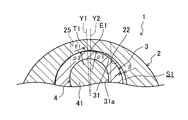
- the plunger 3 has protruding portions 31 protruding so as to be separated from the rotation axis C1 and so that a cross section perpendicular to the rotation axis C1 is curved. As shown in FIG. 5, each of the overhanging portions 31 is fitted into the fitting recesses 22 with a minute gap ⁇ therebetween.
- the overhang surfaces of the overhang portions 31 are curved when viewed in the extending direction of the rotation axis C1, and when the radius of curvature is ⁇ 2 (second radius of curvature), ⁇ 1 ⁇ ⁇ 2.
- a curved concave portion 32 corresponding to each of the bulging portions 21 is formed between the respective protruding portions 31, and between each curved concave portion 32 and the concave groove 21a, A space S2 is formed.
- each projecting portion 31 has a circular cross-sectional slide hole 31a that is gradually inclined away from the rotation axis C1 as it goes to one side in the extending direction of the rotation axis C1. (Linking means) is formed, and the upper surface on one side in the extending direction of the rotation axis C1 in each slide hole 31a is notched and opened.
- each master jaw 4 is formed in a portion communicating with the accommodation space S1 of each guide groove 25. It is inserted.
- a first slide portion 41 having a columnar shape is provided on one end side of the master jaw 4, and the first slide portion 41 is accommodated in the accommodation space S1.
- Each of the first slide portions 41 is inclined so as to gradually move away from the rotation axis C1 as it goes to one side in the extending direction of the rotation axis C1, and is slidably fitted in each slide hole 31a of the plunger 3. It is inserted.
- each slide hole 31 a of the plunger 3 is linked to one end side of each master jaw 4.
- a second slide portion 42 whose cross-sectional shape corresponds to the cross-sectional shape of the guide groove 25 is provided on the other end side of each master jaw 4, and each second slide portion 42 is provided. Are guided in the respective guide grooves 25.
- a slender block-shaped top jaw 5 extending along each second slide portion 42 is fixed to each second slide portion 42 using two bolts B1.
- the slide holes 31a of the plunger 3 are opened as shown in FIG.
- the surface to be formed is configured to press the first slide portion 41 toward the rotation axis C1 while being in sliding contact with the outer peripheral surface of the first slide portion 41 of each master jaw 4.
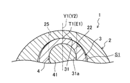
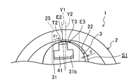
- the fitting recess 22 moves the plunger 3 in the F1 direction so that the top portion T1 of each overhanging portion 31 reaches the inner end E1 of each fitting recess 22 determined in advance by sliding contact with the plunger 3.
- the symmetry axis Y1 passing through the central axis of the plunger 3 in each slide hole 31a is made to coincide with the symmetry axis Y2 passing through the rotation axis C1 in each guide groove 25 of the chuck body 2. That is, each fitting recess 22 is configured to match each slide hole 31 a with a predetermined set position with respect to each guide groove 25.
- each slide hole 31a is moved to a predetermined setting position with respect to each guide groove 25 by the elastic deformation operation of the plunger 3.
- the position of the plunger 3 with respect to the chuck body 2 does not vary, and the gripping position of the workpiece W1 does not deviate from the reference position, so that the workpiece W1 can be gripped with high accuracy.
- the plunger 3 moves relative to the chuck body 2, the protruding surfaces of the protruding portions 31 that are curved come into sliding contact with the inner peripheral surfaces of the curved fitting recesses 22. Therefore, the plunger 3 can be positioned efficiently with respect to the chuck body 2.
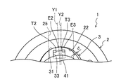
- Embodiment 2 of the Invention 7 and 8 show a chuck device 1 according to Embodiment 2 of the present invention.
- the shape of the accommodation space S1 of the chuck main body 2, the partial structure of the plunger 3, and the structure of the first slide portion 41 in the master jaw 4 are different from those of the first embodiment. Therefore, only the parts different from the first embodiment will be described in detail below.
- the accommodation space S1 of the second embodiment has a substantially triangular shape when viewed in the extending direction of the rotation axis C1, and the bulging portion 21 as in the first embodiment is formed on the inner peripheral surface of the chuck body 2.
- the plunger 3 of the second embodiment includes a plunger body 3b having a substantially triangular shape corresponding to the shape of the housing space S1, and the plunger body 3b has a circular cross section that opens to one side in the extending direction of the rotation axis C1. Mounting recess 3d.
- Each overhanging portion 31 of the second embodiment is provided in the plunger main body 3b, and each overhanging portion 31 has a notch groove in which a cross section in a direction orthogonal to the rotation axis C1 is substantially T-shaped. 33 (linking means) is formed.
- the notch groove 33 has a shape extending in an inclined manner so as to gradually move away from the rotation axis C1 toward the one side in the extension direction of the rotation axis C1, and both ends in the extension direction are open.
- a ring-shaped attachment member 3c is attached to the attachment recess 3d, and the attachment member 3c closes a part of one end side of each notch groove 33.
- the first slide portion 41 of the second embodiment has a substantially T-shaped cross section corresponding to the notch groove 33, and is slidably inserted into the notch groove 33.
- the fitting recesses so that the opening peripheral edges T2 and T3 of the notch grooves 33 in the overhang portions 31 respectively reach the rear end setting portions E2 and E3 of the fitting recesses 22 determined in advance by sliding contact with each other. 22 moves the plunger 3 in the F1 direction so that the symmetry axis Y1 passing through the central axis of the plunger 3 in each notch groove 33 coincides with the symmetry axis Y2 passing through the rotation axis C1 in each guide groove 25 of the chuck body 2. It has become.
- the position of the plunger 3 with respect to the chuck body 2 does not vary when the gripping operation of the workpiece W1 by each top jaw 5 is completed, and the gripping position of the workpiece W1 is changed.
- the workpiece W1 can be gripped with high accuracy without being displaced from the reference position.
- Embodiment 3 of the Invention >> 11 and 12 show a chuck device 1 according to Embodiment 3 of the present invention.
- the structure of the overhanging portion 31 of the plunger 3 and the structure of the first slide portion 41 in the master jaw 4 are different from those of the first embodiment. Only parts different from the first embodiment will be described in detail.
- a slide groove 31b (linking means) having a substantially T-shaped cross section that is gradually inclined away from the rotation axis C1 as it goes to one side in the extension direction of the rotation axis C1. And both ends of the slide groove 31b in the extending direction are open.
- the first slide portion 41 of Embodiment 3 has a substantially T-shaped cross section corresponding to the slide groove 31b, and is slidably inserted into the slide groove 31b.
- the reaction force of the gripping force generated by the gripping operation of the workpiece W1 by the top jaws 5 causes each slide of the plunger 3 to slide. It adds to the part corresponding to the groove
- the fitting is performed so that the opening peripheral edges T2 and T3 of the slide groove 31b in each of the overhanging portions 31 respectively reach the rear end setting portions E2 and E3 of the respective fitting recesses 22 determined in advance by sliding contact with each other.
- the recess 22 moves the plunger 3 in the F1 direction so that the symmetry axis Y1 passing through the central axis of the plunger 3 in each slide groove 31b coincides with the symmetry axis Y2 passing through the rotation axis C1 in each guide groove 25 of the chuck body 2. It is like that.
- the position of the plunger 3 with respect to the chuck body 2 does not vary when the gripping operation of the workpiece W1 by each top jaw 5 is completed, and the workpiece W1 is gripped. Since the position does not deviate from the reference position, the workpiece W1 can be gripped with high accuracy.
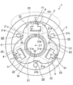
- FIG. 15 shows a chuck device 1 according to Embodiment 4 of the present invention.
- the fourth embodiment since the shape of the accommodation space S1 of the chuck body 2 and the structure of each overhanging portion 31 of the plunger 3 are different from those of the second embodiment, the other parts are the same as those of the second embodiment. Only parts different from the second embodiment will be described in detail.
- a straight line (rotation axis center) perpendicular to the rotation axis C1 and passing through the center of the notch groove 33 is provided on one side in the extending direction of the rotation axis C1 in each protruding portion 31 of the plunger 3 of the fourth embodiment.
- a flat surface portion 31c orthogonal to the symmetry axis Y1) passing through C1 is provided.
- the accommodation space S1 of the fourth embodiment has a regular hexagonal shape in which each corner is gently curved when viewed in the extending direction of the rotation axis C1. That is, six flat surfaces are provided on the inner peripheral surface around the rotation axis C1 of the chuck body 2, and the three flat surfaces orthogonal to the guide grooves 25 correspond to the flat surfaces of the plunger 3.
- the surface portion 31c is a sliding surface portion 26 (positioning portion) that faces with a small gap ⁇ .
- the fitting recess 22 moves the plunger 3 in the F1 direction so that the flat surface portion 31c comes into close contact with the sliding surface portion 26 by sliding on the sliding surface portion 26, and passes through the central axis of the plunger 3 in each notch groove 33.
- the symmetry axis Y1 is made to coincide with the symmetry axis Y2 passing through the rotation axis C1 in each guide groove 25 of the chuck body 2.
- the position of the plunger 3 with respect to the chuck body 2 does not vary when the gripping operation of the workpiece W1 by each top jaw 5 is completed, and the workpiece W1 is gripped. Since the position does not deviate from the reference position, the workpiece W1 can be gripped with high accuracy.
- the chuck body 2 and the plunger 3 can be easily processed as compared with the invention of the second embodiment, and the processing cost is reduced. Can do.
- three of the six surfaces formed around the rotation axis C1 of the chuck body 2 except for the sliding surface portions 26 have a flat shape. 3 may be curved so as to correspond to the outer peripheral surface 3.
- the present invention is suitable for a chuck device used by being attached to a machine tool such as a lathe.
Landscapes
- Engineering & Computer Science (AREA)
- Mechanical Engineering (AREA)
- Gripping On Spindles (AREA)
- Jigs For Machine Tools (AREA)
Abstract
L'invention concerne trois parties concaves d'ajustage (22), ayant chacune une forme incurvée lorsqu'elles sont vues dans la direction d'un axe de rotation (C1), qui sont formées sur une surface circonférentielle interne d'un corps de mandrin (2). Lorsqu'un piston (3) est déformé élastiquement vers l'extérieur au niveau de parties correspondant à chaque trou de coulissement (31a) lorsqu'une pièce à usiner (W1) est saisie par chaque mâchoire supérieure (5), le piston (3) est déplacé en amenant les parties déformées, en raison de la déformation élastique, en contact coulissant avec les parties concaves d'ajustage respectives (22), provoquant ainsi l'alignement des axes symétriques (Y1) des trous de coulissement (31a) sur les axes symétriques (Y2) de rainures de guidage (25) du corps de mandrin (2), respectivement.
Priority Applications (3)
| Application Number | Priority Date | Filing Date | Title |
|---|---|---|---|
| EP17802859.3A EP3450067B1 (fr) | 2016-05-25 | 2017-05-25 | Dispositif de mandrin |
| US16/304,214 US11000904B2 (en) | 2016-05-25 | 2017-05-25 | Chuck device |
| JP2018519591A JP6968788B2 (ja) | 2016-05-25 | 2017-05-25 | チャック装置 |
Applications Claiming Priority (2)
| Application Number | Priority Date | Filing Date | Title |
|---|---|---|---|
| JP2016104282 | 2016-05-25 | ||
| JP2016-104282 | 2016-05-25 |
Publications (1)
| Publication Number | Publication Date |
|---|---|
| WO2017204273A1 true WO2017204273A1 (fr) | 2017-11-30 |
Family
ID=60411793
Family Applications (1)
| Application Number | Title | Priority Date | Filing Date |
|---|---|---|---|
| PCT/JP2017/019452 Ceased WO2017204273A1 (fr) | 2016-05-25 | 2017-05-25 | Dispositif de mandrin |
Country Status (5)
| Country | Link |
|---|---|
| US (1) | US11000904B2 (fr) |
| EP (1) | EP3450067B1 (fr) |
| JP (1) | JP6968788B2 (fr) |
| TW (1) | TWI714770B (fr) |
| WO (1) | WO2017204273A1 (fr) |
Cited By (1)
| Publication number | Priority date | Publication date | Assignee | Title |
|---|---|---|---|---|
| JP2020196104A (ja) * | 2019-06-04 | 2020-12-10 | 株式会社北川鉄工所 | チャック |
Families Citing this family (4)
| Publication number | Priority date | Publication date | Assignee | Title |
|---|---|---|---|---|
| CN112296752A (zh) * | 2019-07-30 | 2021-02-02 | 陈昱廷 | 车床夹持机构夹持力实时线上量测装置 |
| CN110935898A (zh) * | 2019-12-23 | 2020-03-31 | 有研亿金新材料有限公司 | 一种数控机床夹具 |
| CN111438383B (zh) * | 2020-03-05 | 2022-03-29 | 湖北隐冠轴业有限公司 | 一种空心轴加工自动纠偏方法及装置 |
| CN114472941A (zh) * | 2022-02-08 | 2022-05-13 | 浙江瑞力特种紧固件有限公司 | 一种转轴加工用辅助装置 |
Citations (4)
| Publication number | Priority date | Publication date | Assignee | Title |
|---|---|---|---|---|
| JPS62213906A (ja) * | 1986-03-14 | 1987-09-19 | Kitagawa Tekkosho:Kk | くさび式チヤツクにおけるジヨウ作動体構造 |
| JPH08168906A (ja) * | 1995-06-21 | 1996-07-02 | Kitagawa Iron Works Co Ltd | 精密チャック |
| JP2011177871A (ja) * | 2010-03-03 | 2011-09-15 | Kitagawa Iron Works Co Ltd | チャックの作動体構造 |
| JP2015058529A (ja) * | 2013-09-20 | 2015-03-30 | 株式会社北川鉄工所 | 引き込み機構を持つチャック装置 |
Family Cites Families (13)
| Publication number | Priority date | Publication date | Assignee | Title |
|---|---|---|---|---|
| US1305138A (en) * | 1919-05-27 | mcclellan | ||
| US2697612A (en) * | 1950-04-01 | 1954-12-21 | Cushman Chuck Co | Lightweight chuck |
| DE2903904C3 (de) * | 1979-02-02 | 1986-07-10 | Paul Forkardt GmbH & Co KG, 4000 Düsseldorf | Kraftbetätigtes Backenfutter |
| DE3212759A1 (de) * | 1982-04-06 | 1983-10-06 | Forkardt Paul Gmbh | Umlaufende spannvorrichtung |
| JPH05212608A (ja) | 1991-02-12 | 1993-08-24 | Kitagawa Iron Works Co Ltd | 爪を内方側から組込むチャック |
| DE4143428A1 (de) | 1991-11-14 | 1993-09-09 | Siegfried Gulde | Backenfutter fuer werkzeugmaschinen |
| TW557238B (en) | 2001-07-18 | 2003-10-11 | Kitagawa Iron Works Co | Chuck with pull-in function |
| HU226381B1 (hu) * | 2004-08-25 | 2008-10-28 | Jozsef Dr Tajnafoei | Befogótokmány a rugalmas gyártáshoz |
| JP4895688B2 (ja) | 2006-05-30 | 2012-03-14 | 株式会社北川鉄工所 | チャック装置 |
| JP5009838B2 (ja) * | 2008-03-05 | 2012-08-22 | オークマ株式会社 | ワークの支持装置および回転割出機 |
| CA2767551A1 (fr) * | 2009-07-06 | 2011-01-13 | Aker Mh As | Moyen de centrage dans une cle a couple |
| TWM376375U (en) * | 2009-11-06 | 2010-03-21 | Okina Automation Co Ltd | High-power ultra-thin type clamping head |
| JP6345321B1 (ja) * | 2017-07-28 | 2018-06-20 | 株式会社北川鉄工所 | チャック機構 |
-
2017
- 2017-05-25 WO PCT/JP2017/019452 patent/WO2017204273A1/fr not_active Ceased
- 2017-05-25 US US16/304,214 patent/US11000904B2/en active Active
- 2017-05-25 TW TW106117353A patent/TWI714770B/zh active
- 2017-05-25 JP JP2018519591A patent/JP6968788B2/ja active Active
- 2017-05-25 EP EP17802859.3A patent/EP3450067B1/fr active Active
Patent Citations (4)
| Publication number | Priority date | Publication date | Assignee | Title |
|---|---|---|---|---|
| JPS62213906A (ja) * | 1986-03-14 | 1987-09-19 | Kitagawa Tekkosho:Kk | くさび式チヤツクにおけるジヨウ作動体構造 |
| JPH08168906A (ja) * | 1995-06-21 | 1996-07-02 | Kitagawa Iron Works Co Ltd | 精密チャック |
| JP2011177871A (ja) * | 2010-03-03 | 2011-09-15 | Kitagawa Iron Works Co Ltd | チャックの作動体構造 |
| JP2015058529A (ja) * | 2013-09-20 | 2015-03-30 | 株式会社北川鉄工所 | 引き込み機構を持つチャック装置 |
Non-Patent Citations (1)
| Title |
|---|
| See also references of EP3450067A4 * |
Cited By (2)
| Publication number | Priority date | Publication date | Assignee | Title |
|---|---|---|---|---|
| JP2020196104A (ja) * | 2019-06-04 | 2020-12-10 | 株式会社北川鉄工所 | チャック |
| JP7393878B2 (ja) | 2019-06-04 | 2023-12-07 | 株式会社北川鉄工所 | チャック |
Also Published As
| Publication number | Publication date |
|---|---|
| JP6968788B2 (ja) | 2021-11-17 |
| US11000904B2 (en) | 2021-05-11 |
| US20200316692A1 (en) | 2020-10-08 |
| EP3450067A1 (fr) | 2019-03-06 |
| TWI714770B (zh) | 2021-01-01 |
| TW201803665A (zh) | 2018-02-01 |
| JPWO2017204273A1 (ja) | 2019-03-22 |
| EP3450067A4 (fr) | 2019-05-22 |
| EP3450067B1 (fr) | 2023-08-09 |
Similar Documents
| Publication | Publication Date | Title |
|---|---|---|
| JPWO2017204273A1 (ja) | チャック装置 | |
| KR20180096749A (ko) | 인입형 척 | |
| EP3546096A1 (fr) | Dispositif de mandrin | |
| CN107848042A (zh) | 卡盘装置 | |
| JP2019509179A (ja) | 工作機械上で被加工物をロックする装置 | |
| KR200472903Y1 (ko) | 링 가공용 소프트조 | |
| KR101948787B1 (ko) | 풀다운 척의 공작물 클램핑장치 | |
| JP6654405B2 (ja) | チャック装置 | |
| JP3597220B2 (ja) | 工作物取付治具 | |
| JP2011177871A (ja) | チャックの作動体構造 | |
| JP2015150649A (ja) | チャック装置 | |
| JP7023941B2 (ja) | チャック機構 | |
| JP2014034105A (ja) | フィンガーチャック | |
| JP4205970B2 (ja) | コレットチャック装置 | |
| JP4290422B2 (ja) | 素材把持装置及び自動旋盤 | |
| JP6979762B2 (ja) | グリッパ | |
| JP2017100244A (ja) | 中空ワークの位置決め方法 | |
| JP5694267B2 (ja) | チャック | |
| JP4897557B2 (ja) | チャック装置 | |
| JP2008532785A (ja) | 回転マシンを装填するための工具保持用のチャック | |
| JP4895688B2 (ja) | チャック装置 | |
| KR20260064732A (ko) | 공작 기계 | |
| JPS5944162B2 (ja) | 工作機械のワ−ク把持装置 | |
| JP6685693B2 (ja) | 回転動力伝達装置 | |
| JP2014061573A (ja) | コレットチャック装置およびこのコレットチャック装置を備えた工作機械 |
Legal Events
| Date | Code | Title | Description |
|---|---|---|---|
| WWE | Wipo information: entry into national phase |
Ref document number: 2018519591 Country of ref document: JP |
|
| NENP | Non-entry into the national phase |
Ref country code: DE |
|
| 121 | Ep: the epo has been informed by wipo that ep was designated in this application |
Ref document number: 17802859 Country of ref document: EP Kind code of ref document: A1 |
|
| ENP | Entry into the national phase |
Ref document number: 2017802859 Country of ref document: EP Effective date: 20181130 |