WO2017208455A1 - スクロール圧縮機 - Google Patents
スクロール圧縮機 Download PDFInfo
- Publication number
- WO2017208455A1 WO2017208455A1 PCT/JP2016/066656 JP2016066656W WO2017208455A1 WO 2017208455 A1 WO2017208455 A1 WO 2017208455A1 JP 2016066656 W JP2016066656 W JP 2016066656W WO 2017208455 A1 WO2017208455 A1 WO 2017208455A1
- Authority
- WO
- WIPO (PCT)
- Prior art keywords
- scroll
- sliding surface
- metal member
- thrust sliding
- scroll compressor
- Prior art date
- Legal status (The legal status is an assumption and is not a legal conclusion. Google has not performed a legal analysis and makes no representation as to the accuracy of the status listed.)
- Ceased
Links
Images


Classifications
-
- F—MECHANICAL ENGINEERING; LIGHTING; HEATING; WEAPONS; BLASTING
- F04—POSITIVE - DISPLACEMENT MACHINES FOR LIQUIDS; PUMPS FOR LIQUIDS OR ELASTIC FLUIDS
- F04C—ROTARY-PISTON, OR OSCILLATING-PISTON, POSITIVE-DISPLACEMENT MACHINES FOR LIQUIDS; ROTARY-PISTON, OR OSCILLATING-PISTON, POSITIVE-DISPLACEMENT PUMPS
- F04C18/00—Rotary-piston pumps specially adapted for elastic fluids
- F04C18/02—Rotary-piston pumps specially adapted for elastic fluids of arcuate-engagement type, i.e. with circular translatory movement of co-operating members, each member having the same number of teeth or tooth-equivalents
Definitions
- the present invention relates to a scroll compressor used for air conditioning or freezing.
- scroll compressors are known as compressors used for air conditioning or refrigeration.
- the scroll compressor disclosed in Patent Document 1 includes a fixed scroll having plate-like spiral teeth, and an orbiting scroll having plate-like spiral teeth that mesh with the plate-like spiral teeth of the fixed scroll.
- the scroll compressor includes a slider that makes the swing radius of the swing scroll variable, a balance weight that cancels the centrifugal force of the swing scroll generated by the swing motion, a fixed scroll, a swing scroll, and a balance.
- a frame that accommodates the weight and supports the thrust bearing surface of the orbiting scroll in a freely swingable manner on the thrust sliding surface.
- the main shaft having an eccentric shaft rotates, and thereby the orbiting scroll is swung to perform compression while reducing the volume toward the center of the compression chamber.
- a scroll compressor having a balance weight on the slider requires a space for rotating the balance weight, so the inner diameter of the thrust sliding surface of the frame is large. Become. Therefore, in this scroll compressor, the area of the thrust sliding surface of the frame is reduced and the thrust load per unit area of the orbiting scroll is increased, so that the orbiting scroll thrust bearing surface may be abnormally worn or seized. There is.
- the present invention has been made to solve the above-described problems, and is a scroll compressor that can secure the area of the thrust sliding surface of the frame and reduce abnormal wear and seizure of the orbiting scroll thrust bearing surface.
- the purpose is to provide.
- the scroll compressor according to the present invention includes a sealed container, a fixed scroll provided in the sealed container and having a first spiral protrusion, a second scroll protrusion provided in the sealed container, An orbiting scroll that forms a compression chamber for compressing a refrigerant between the fixed scroll, a main shaft having an eccentric shaft portion that causes the orbiting scroll to swing, and between the orbiting scroll and the eccentric shaft portion.
- an annular metal member having an outer diameter corresponding to the outer diameter of the thrust sliding surface and having an inner diameter smaller than the inner diameter of the thrust sliding surface.
- a scroll compressor according to the present invention is installed on a thrust sliding surface, has an outer diameter corresponding to the outer diameter of the thrust sliding surface, and has an annular shape having an inner diameter smaller than the inner diameter of the thrust sliding surface. Since the metal member is provided, even if the balance weight is provided, the area of the thrust sliding surface can be ensured by the annular metal member. In other words, the scroll compressor according to the present invention can reduce the thrust load per unit area of the orbiting scroll by supporting the thrust load with the annular metal member, so that the abnormal wear of the orbiting scroll thrust sliding surface can be reduced. In addition, seizure can be reduced.
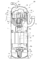
- FIG. 1 is a longitudinal sectional view of a scroll compressor according to Embodiment 1 of the present invention.
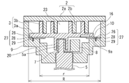
- FIG. 2 is an enlarged cross-sectional view of the main part of the scroll compressor according to Embodiment 1 of the present invention.
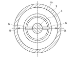
- FIG. 3 is an enlarged cross-sectional view showing a relationship between the frame of the scroll compressor according to Embodiment 1 of the present invention and an annular metal member.
- the scroll compressor 100 demonstrated here shows the example of a vertical installation type, this invention is applicable also to a horizontal installation type.
- the relationship of the size of each component may be different from the actual one.
- the scroll compressor 100 is one of components of a refrigeration cycle used in various industrial machines such as a refrigerator, a freezer, a vending machine, an air conditioner, a refrigeration apparatus, or a water heater. .
- the scroll compressor 100 sucks the refrigerant circulating in the refrigeration cycle, compresses it, and discharges it as a high-temperature and high-pressure state.
- the scroll compressor 100 has a compression mechanism in which a fixed scroll 2 and a swing scroll 3 that swings with respect to the fixed scroll 2 are combined inside a main body shell 1 that is a sealed dome-type sealed container. Has been implemented.
- the scroll compressor 100 includes an electric motor 22 including an electric rotary machine or the like inside the main body shell 1. Inside the main body shell 1, the compression mechanism is disposed on the upper side, and the electric motor 22 is disposed on the lower side.
- the main body shell 1 is formed in a cylindrical shape having a sealed space and has pressure resistance.
- a suction pipe 14 for taking in the refrigerant into the main body shell 1 is connected to the side surface of the main body shell 1, and a discharge pipe 15 for discharging the compressed refrigerant from the main body shell 1 is connected to the upper surface.
- a frame 9 that houses the compression mechanism and supports the swing scroll 3 so as to be swingable is fixed to the upper portion of the main body shell 1.
- the frame 9 includes a thrust sliding surface 9a and supports the orbiting scroll 3 on the thrust sliding surface 9a.
- a subframe 24 that holds the main shaft 5 that is rotated by the rotation of the electric motor 22 is fixed to the lower side of the main body shell 1. Further, an oil sump 12 for storing the lubricating oil 11 is formed at the bottom of the main body shell 1.
- the fixed scroll 2 includes a fixed scroll base plate 2a and a first spiral protrusion 2b that is a spiral protrusion standing on the lower surface of the fixed scroll base plate 2a.
- the orbiting scroll 3 includes an orbiting scroll base plate 3a and a second spiral protrusion 3b that is a spiral protrusion standing on the upper surface of the orbiting scroll base plate 3a.
- the orbiting scroll 3 is installed eccentrically with respect to the fixed scroll 2, and the first spiral protrusion 2b of the fixed scroll 2 and the second spiral protrusion 3b of the orbiting scroll 3 are combined to compress the refrigerant.
- a compression chamber 23 is formed. Note that the surface (the lower surface in the illustrated example) of the swing scroll base plate 3a on which the second spiral protrusion 3b is not formed functions as the swing scroll thrust bearing surface 16.
- the fixed scroll 2 is fixed to the upper surface of the frame 9 with bolts 30.
- the fixed scroll 2 is formed with a discharge port 17 that discharges a compressed refrigerant at a high temperature and a high pressure at the center of the fixed scroll base plate 2a.
- the compressed high-temperature and high-pressure refrigerant is discharged from the discharge port 17 to the high-pressure chamber 18 above the fixed scroll 2, passes through the discharge pipe 15, and is discharged outside the main body shell 1.
- the discharge port 17 is provided with a discharge valve 19 that prevents the refrigerant from flowing backward.
- the orbiting scroll 3 performs an oscillating motion without rotating with respect to the fixed scroll 2 by an Oldham ring 6 for preventing the rotating motion.
- a hollow cylindrical boss portion 20 is formed at the center of the surface of the orbiting scroll 3 where the second spiral protrusion 3b is not formed (the lower surface in the illustrated example).
- the swing scroll 3 swings on the thrust sliding surface 9a of the frame 9 as the eccentric shaft portion 5a provided at the upper end of the main shaft 5 inserted into the boss portion 20 rotates.
- the Oldham ring 6 is slidably housed in an Oldham groove (not shown) formed on an orbiting scroll thrust bearing surface 16 of the orbiting scroll 3 with an Oldham claw projecting upward and protrudes downward.
- the Oldham claw is stored and installed in the Oldham keyway 6a formed in the frame 9 so as to be slidable.
- the Oldham ring 6 may be installed on the formation surface side of the second spiral protrusion 3b of the swing scroll 3 of the swing scroll base plate 3a.
- the frame 9 is formed in a cylindrical shape that tapers downward in a stepwise manner, and accommodates the swing scroll 3 in a slidable manner.
- a sliding surface is formed by the thrust sliding surface 9a inside the frame 9 and the lower surface of the swing scroll base plate 3a.
- the frame 9 is provided with an annular metal member 10 on the thrust sliding surface 9 a and between the swing scroll thrust bearing surface 16 of the swing scroll 3. ing.
- the annular metal member 10 can be made of, for example, a casting, iron-based, or aluminum-based material as a metal having excellent wear resistance that can withstand a thrust load.
- the annular metal member 10 has an outer diameter corresponding to the outer diameter R of the thrust sliding surface 9a and an inner diameter smaller than the inner diameter r of the thrust sliding surface 9a.
- the outer diameter corresponding to the outer diameter R of the thrust sliding surface 9a is substantially the same as the outer diameter R of the thrust sliding surface 9a.
- a first screw hole 28 penetrating toward the thrust sliding surface 9a is formed in the annular metal member 10.
- a second screw hole 29 is formed in the thrust sliding surface 9 a of the frame 9 at a position common to the first screw hole 28.
- the annular metal member 10 has a fixing portion 27 that is screwed to the frame 9 by screwing the screw member 26 passed through the first screw hole 28 into the second screw hole 29.
- the first screw hole 28 has such a size and shape that the head of the screw member 26 is completely accommodated in the first screw hole 28 and does not hinder the swinging motion of the swing scroll 3.
- the means for fixing the annular metal member 10 to the frame 9 is not limited to the fixing portion 27 fixed with screws.
- the annular metal member 10 may have a configuration in which the outer peripheral surface is fixed by being shrink-fitted on the inner peripheral surface of the frame 9. In short, if the annular metal member 10 can be fixed to the frame 9, it can be implemented in various modes.
- the electric motor 22 includes an annular stator 21 that is fixedly supported on the inner wall surface of the main body shell 1 by shrink fitting or the like, and a rotor 4 that is rotatably attached to the inner surface of the stator 21. It drives the compression mechanism connected via the main shaft 5.
- the main shaft 5 is inserted into the boss portion 20 of the orbiting scroll 3 at the upper end and is rotatably supported, and an eccentric shaft portion 5a that engages with the orbiting scroll 3 on an eccentric shaft that is eccentric from the center of rotation of the main shaft 5 is provided. Is formed.
- the main shaft 5 is configured to rotate with the rotation of the rotor 4 and rotate the orbiting scroll 3 with the eccentric shaft portion 5a.
- the upper portion of the main shaft 5 (in the vicinity of the eccentric shaft portion 5a) is rotatably supported by a main bearing 25a provided at the center portion of the frame 9.
- the lower portion of the main shaft 5 is rotatably supported by the auxiliary bearing 25b.
- the sub bearing 25 b is press-fitted and fixed to a bearing housing portion 24 a formed at the center portion of the sub frame 24 provided at the lower portion of the main body shell 1.
- the sub frame 24 is provided with an oil pump 13. The lubricating oil 11 sucked by the oil pump 13 is sent to each sliding portion through the main shaft oil supply hole 5b formed in the main shaft 5.
- the main shaft 5 is provided with a balance weight 8 that cancels out the centrifugal force of the orbiting scroll 3 generated by the orbiting motion.
- the balance weight 8 is disposed on the opposite side of the direction of the centrifugal force acting on the orbiting scroll 3 and is formed integrally with the slider 7. The balance weight 8 can reduce the pressing of the second spiral protrusion 3b against the first spiral protrusion 2b.
- the slider 7 is rotatably inserted into the boss portion 20, and an eccentric shaft portion 5 a of the main shaft 5 provided at the upper end of the main shaft 5 is inserted into the slide surface. That is, the slider 7 is interposed between the orbiting scroll 3 and the eccentric shaft portion 5a of the main shaft 5, makes the orbiting scroll 3 have a variable orbiting radius, and swings in order to make the orbiting scroll 3 revolve.
- the moving scroll 3 is supported.
- the refrigerant to be compressed flows in from the suction pipe 14, is taken into the compression chamber 23 through a suction port (not shown) provided in the frame 9, is compressed, and is compressed from the discharge port 17 at the center of the fixed scroll base plate 2a. It is discharged outside the main body shell 1 through the discharge pipe 15 through the chamber 18.
- the lubricating oil 11 flows from the oil reservoir 12 at the bottom of the main body shell 1 through the oil pump 13 through the oil pump 13 and is supplied to the bearings, the space on the sliding portion side, etc., and is formed in the frame 9.
- An oil drain hole (not shown) is returned to the oil sump 12.
- the inner diameter r of the thrust sliding surface 9a is increased. That is, in the scroll compressor 100, since the area of the thrust sliding surface 9a of the orbiting scroll 3 is reduced, the thrust load per unit area of the orbiting scroll 3 is increased and the orbiting scroll thrust bearing surface 16 is abnormally worn. Or it may cause seizure.
- the thrust sliding surface 9a has an outer diameter corresponding to the outer diameter R of the thrust sliding surface 9a, and the thrust sliding surface 9a An annular metal member 10 having an inner diameter smaller than the inner diameter r is installed. That is, since the annular metal member 10 having an area larger than the area of the thrust sliding surface 9a is installed on the thrust sliding surface 9a, the annular metal member 10 is provided even if the balance weight 8 is provided. Thus, the area of the thrust sliding surface 9a can be secured. Therefore, the scroll compressor 100 according to the first embodiment can reduce the thrust load per unit area of the orbiting scroll 3, and can reduce abnormal wear and seizure of the orbiting scroll thrust bearing surface 16. .
- the annular metal member 10 is fixed to the frame 9 with the screw member 26 inserted in the first screw hole 28 and the second screw hole 29 in common, the rocking scroll 3 is swung. It never rotates with respect to the movement, and the effect of preventing the abnormal wear and seizure of the swing scroll thrust bearing surface 16 can be enhanced.
- the annular metal member 10 has its outer peripheral surface fixed by being shrink-fitted to the inner peripheral surface of the frame 9, thereby enhancing the effect of preventing abnormal wear and seizure of the orbiting scroll thrust bearing surface 16. Can do.
- FIG. 4 is an enlarged cross-sectional view showing a different form of the main part of the scroll compressor according to Embodiment 1 of the present invention.
- the annular metal member 10 may have a configuration in which the center of the inner diameter is eccentric from the center of the outer diameter. That is, it is possible to effectively reduce the thrust load by increasing the sliding area of the portion (the left side in the case of FIG. 4) where the thrust load of the orbiting scroll 3 acts particularly.
- the annular metal member 10 has a surface facing the orbiting scroll thrust bearing surface 16 as an inclined surface that descends from the outer periphery toward the inner periphery, and It is good also as a structure corresponding to the bending of the rocking scroll thrust bearing surface 16 by rocking motion.
- FIG. 5 is an enlarged cross-sectional view showing the configuration of the annular metal member of the scroll compressor according to Embodiment 2 of the present invention.
- the description is abbreviate
- annular first oil supply groove 10a is formed on a surface of the annular metal member 10 facing the swing scroll thrust bearing surface 16.
- circular shaped metal member 10 is formed, It is characterized by the above-mentioned.
- the first oil supply groove 10a is composed of a small-diameter oil supply groove and a large-diameter oil supply groove formed at intervals.
- two second oil supply grooves 10b are formed with an interval of approximately 180 degrees, and intersect with the first oil supply groove 10a.
- the scroll compressor 100 of the second embodiment the lubricating oil 11 sucked up by the oil pump 13 from the oil reservoir 12 and accumulated in the frame 9 passes through the first oil supply groove 10a and the second oil supply groove 10b.
- the rocking scroll thrust bearing surface 16 is spread. Therefore, the scroll compressor 100 according to the second embodiment can increase the amount of oil supplied to the thrust surface, so that the thrust slide can be performed smoothly, and abnormal wear and seizure of the orbiting scroll thrust bearing surface 16 occur. The prevention effect can be enhanced.
- Embodiment 2 shown in FIG. 5 although the structure which formed both the 1st oil supply groove
- the present invention has been described above based on the embodiment, the present invention is not limited to the configuration of the embodiment described above.
- the illustrated internal configuration of the scroll compressor 100 is an example, and is not limited to the above-described content, and the scroll compressor 100 including other components can be similarly implemented.
- the scope of the present invention also includes the scope of various changes, applications, and uses made by those skilled in the art as needed.
Landscapes
- Engineering & Computer Science (AREA)
- Mechanical Engineering (AREA)
- General Engineering & Computer Science (AREA)
- Rotary Pumps (AREA)
Abstract
スクロール圧縮機は、密閉容器と、密閉容器内に設けられ、第1渦巻突起部を有する固定スクロールと、密閉容器内に設けられ、第2渦巻突起部を有し、固定スクロールとの間に冷媒を圧縮する圧縮室を形成する揺動スクロールと、揺動スクロールを揺動運動させる偏心軸部を有する主軸と、揺動スクロールと偏心軸部との間に介在するスライダと、スライダに設けられたバランスウェイトと、揺動スクロールに作用する荷重を支持する円環状のスラスト摺動面を有する筒状のフレームと、スラスト摺動面上に設置され、スラスト摺動面の外径に相当する外径を有し、かつスラスト摺動面の内径よりも小さい内径を有する円環状の金属部材と、を備えている。
Description
本発明は、空調又は冷凍等に用いられるスクロール圧縮機に関するものである。
従来、空調又は冷凍等に用いられる圧縮機としてスクロール圧縮機が知られている。例えば、特許文献1に開示されたスクロール圧縮機では、板状渦巻き歯を有する固定スクロールと、固定スクロールの板状渦巻き歯に対向して噛み合う板状渦巻き歯を有する揺動スクロールとを備えている。また、このスクロール圧縮機には、揺動スクロールの揺動半径を可変とするスライダと、揺動運動により発生する揺動スクロールの遠心力を相殺するバランスウェイトと、固定スクロール、揺動スクロール及びバランスウェイトを収納すると共に揺動スクロールのスラスト軸受面をスラスト摺動面で揺動自在に支持するフレームと、を備えている。このスクロール圧縮機は、偏心軸を有する主軸が回転することにより、揺動スクロールを旋回運動させ、圧縮室の中心に向かって容積を減少させながら圧縮が行われるものである。
特許文献1に開示されたスクロール圧縮機のように、スライダにバランスウェイトを備えたスクロール圧縮機では、バランスウェイトを回転させるためのスペースが必要となるため、フレームのスラスト摺動面の内径が大きくなる。そのため、このスクロール圧縮機は、フレームのスラスト摺動面の面積が減少し、揺動スクロールの単位面積当たりのスラスト荷重が大きくなるので、揺動スクロールスラスト軸受面が異常摩耗し、又は焼付くおそれがある。
本発明は、上記のような課題を解決するためになされたもので、フレームのスラスト摺動面の面積を確保して、揺動スクロールスラスト軸受面の異常摩耗及び焼付きを低減できるスクロール圧縮機を提供することを目的とする。
本発明に係るスクロール圧縮機は、密閉容器と、前記密閉容器内に設けられ、第1渦巻突起部を有する固定スクロールと、前記密閉容器内に設けられ、第2渦巻突起部を有し、前記固定スクロールとの間に冷媒を圧縮する圧縮室を形成する揺動スクロールと、前記揺動スクロールを揺動運動させる偏心軸部を有する主軸と、前記揺動スクロールと前記偏心軸部との間に介在するスライダと、前記スライダに設けられたバランスウェイトと、前記揺動スクロールに作用する荷重を支持する円環状のスラスト摺動面を有する筒状のフレームと、前記スラスト摺動面上に設置され、前記スラスト摺動面の外径に相当する外径を有し、かつ前記スラスト摺動面の内径よりも小さい内径を有する円環状の金属部材と、を備えたものである。
本発明に係るスクロール圧縮機は、スラスト摺動面上に設置され、スラスト摺動面の外径に相当する外径を有し、かつスラスト摺動面の内径よりも小さい内径を有する円環状の金属部材を備えているので、バランスウェイトを有していたとしても、円環状の金属部材でスラスト摺動面の面積を確保することができる。つまり、本発明に係るスクロール圧縮機は、スラスト荷重を円環状の金属部材で支持することにより、揺動スクロールの単位面積当たりのスラスト荷重を小さくできるので、揺動スクロールスラスト摺動面の異常摩耗及び焼付きを低減することができる。
実施の形態1.
以下、本発明の実施の形態1に係るスクロール圧縮機を図1~図4に基づいて説明する。図1は、本発明の実施の形態1に係るスクロール圧縮機の縦断面図である。図2は、本発明の実施の形態1に係るスクロール圧縮機の主要部を拡大して示した断面図である。図3は、本発明の実施の形態1に係るスクロール圧縮機のフレームと円環状の金属部材との関係を拡大して示した横断面図である。なお、ここで説明するスクロール圧縮機100は、縦置き型の例を示すが、横置き型のものにも本発明を適用できるものである。また、図1を含め、以下の図面では各構成部材の大きさの関係が実際のものとは異なる場合がある。
以下、本発明の実施の形態1に係るスクロール圧縮機を図1~図4に基づいて説明する。図1は、本発明の実施の形態1に係るスクロール圧縮機の縦断面図である。図2は、本発明の実施の形態1に係るスクロール圧縮機の主要部を拡大して示した断面図である。図3は、本発明の実施の形態1に係るスクロール圧縮機のフレームと円環状の金属部材との関係を拡大して示した横断面図である。なお、ここで説明するスクロール圧縮機100は、縦置き型の例を示すが、横置き型のものにも本発明を適用できるものである。また、図1を含め、以下の図面では各構成部材の大きさの関係が実際のものとは異なる場合がある。
実施の形態1に係るスクロール圧縮機100は、たとえば冷蔵庫、冷凍庫、自動販売機、空気調和装置、冷凍装置又は給湯器等の各種産業機械に用いられる冷凍サイクルの構成要素の一つとなるものである。スクロール圧縮機100は、冷凍サイクルを循環する冷媒を吸入し、圧縮して高温高圧の状態として吐出させる。スクロール圧縮機100は、図1に示すように、密閉ドーム型の密閉容器である本体シェル1の内部に固定スクロール2と固定スクロール2に対して揺動する揺動スクロール3を組み合わせた圧縮機構が実装されている。また、スクロール圧縮機100は、本体シェル1の内部に電動回転機械等からなる電動機22を備えている。本体シェル1の内部において、圧縮機構が上側に、電動機22が下側に、それぞれ配置されている。
本体シェル1は、図1に示すように、密閉空間を有する円筒形状に形成されたものであって耐圧性を有している。本体シェル1の側面には冷媒を本体シェル1内に取り込むための吸入管14が接続されており、上面には圧縮した冷媒を本体シェル1から吐き出す吐出管15が接続されている。本体シェル1の上部側には、圧縮機構を収納するとともに揺動スクロール3を揺動自在に支持するフレーム9が固定されている。フレーム9は、スラスト摺動面9aを備え、そのスラスト摺動面9a上で揺動スクロール3を支持している。また、本体シェル1の下部側には、電動機22の回転駆動により回転する主軸5を保持するサブフレーム24が固定されている。更に、本体シェル1の底部には潤滑油11を貯留する油溜め12が形成されている。
固定スクロール2は、図1及び図2に示すように、固定スクロール台板2aと、固定スクロール台板2aの下面に立設された渦巻突起である第1渦巻突起部2bと、で構成されている。揺動スクロール3は、揺動スクロール台板3aと、揺動スクロール台板3aの上面に立設された渦巻突起である第2渦巻突起部3bと、で構成されている。揺動スクロール3は、固定スクロール2に対して偏心させて設置されており、固定スクロール2の第1渦巻突起部2bと揺動スクロール3の第2渦巻突起部3bとが組み合わされて冷媒を圧縮する圧縮室23が形成されている。なお、揺動スクロール台板3aの第2渦巻突起部3bが形成されていない側の面(図示例の場合は下面)は、揺動スクロールスラスト軸受面16として作用する。
固定スクロール2は、フレーム9の上面にボルト30で固定されている。固定スクロール2は、固定スクロール台板2aの中央部に、圧縮され、高温、高圧となった冷媒を吐出する吐出ポート17が形成されている。圧縮された高温、高圧冷媒は、吐出ポート17から固定スクロール2上部の高圧室18に排出され、吐出管15を通り、本体シェル1外へ吐出される。吐出ポート17には、冷媒の逆流を防ぐ吐出弁19が設けられている。
揺動スクロール3は、自転運動を阻止するためのオルダムリング6により、固定スクロール2に対して自転運動することなく揺動運動を行うようになっている。また、揺動スクロール3の第2渦巻突起部3bが形成されていない側の面(図示例の場合は下面)の中心部には、中空円筒形状のボス部20が形成されている。揺動スクロール3は、ボス部20に挿入された主軸5の上端に設けた偏心軸部5aが回転することで、フレーム9のスラスト摺動面9a上で揺動運動する。
オルダムリング6は、上方に向かって突出したオルダム爪が揺動スクロール3の揺動スクロールスラスト軸受面16に形成されたオルダム溝(図示は省略)に摺動可能に収納され、下方に向かって突出したオルダム爪がフレーム9に形成されたオルダムキー溝6aに、摺動できるように収納され設置されている。なお、オルダムリング6は、揺動スクロール台板3aの揺動スクロール3の第2渦巻突起部3bの形成面側に設置するようにしてもよい。
フレーム9は、図1及び図2に示すように、下方に向かって段階的に先細る円筒状で構成されており、揺動スクロール3を摺動自在に収納するものである。フレーム9内側のスラスト摺動面9aと、揺動スクロール台板3aの下面とで摺動面が形成されている。フレーム9には、図2及び図3に示すように、スラスト摺動面9a上であって、揺動スクロール3の揺動スクロールスラスト軸受面16との間に円環状の金属部材10が設置されている。円環状の金属部材10は、スラスト荷重に耐えうる耐摩耗性に優れた金属として、例えば、鋳物、鉄系、アルミ系の材料を使用することができる。円環状の金属部材10は、スラスト摺動面9aの外径Rに相当する外径を有し、かつスラスト摺動面9aの内径rよりも小さい内径を有している。なお、スラスト摺動面9aの外径Rに相当する外径とは、スラスト摺動面9aの外径Rとほぼ同じ寸法である。
円環状の金属部材10には、スラスト摺動面9aに向かって貫通する第1ネジ孔28が形成されている。一方、フレーム9のスラスト摺動面9aには、第1ネジ孔28と共通する位置に第2ネジ孔29が形成されている。円環状の金属部材10は、第1ネジ孔28に通したネジ部材26を第2ネジ孔29にねじ込んでフレーム9にネジ固定された固定部27を有している。なお、第1ネジ孔28は、ネジ部材26の頭部が第1ネジ孔28の内部に完全に収まる大きさ及び形状であり、揺動スクロール3の揺動運動を阻害しない構成としている。
円環状の金属部材10をフレーム9へ固定する手段としては、上記したネジ固定した固定部27に限定されない。例えば、円環状の金属部材10は、その外周面をフレーム9の内周面に焼きばめられて固定された構成でもよい。要するに、円環状の金属部材10をフレーム9に固定することができれば、種々の態様で実施することができる。
電動機22は、本体シェル1の内壁面に焼き嵌め等により固着支持された円環状の固定子21と、固定子21の内側面に対向して回転可能に取り付けられた回転子4とで構成されており、主軸5を介して連結された圧縮機構を駆動させるものである。
主軸5は、上端部に揺動スクロール3のボス部20に挿入されて回転自在に支持され、主軸5の回転中心から偏心した偏心軸上で揺動スクロール3に係合する偏心軸部5aが形成されている。主軸5は、回転子4の回転に伴って回転し、偏心軸部5aで揺動スクロール3を旋回させる構成である。主軸5の上部(偏心軸部5a近傍)は、フレーム9の中央部に設けられた主軸受25aに回転自在に支持されている。一方、主軸5の下部は、副軸受25bによって回転自在に支持されている。副軸受25bは、本体シェル1の下部に設けられたサブフレーム24の中央部に形成された軸受収納部24aに圧入固定されている。また、サブフレーム24には、オイルポンプ13が設けられている。このオイルポンプ13で吸引された潤滑油11は、主軸5の内部に形成された主軸内給油穴5bを介して各摺動部に送られる。
また、主軸5には、揺動運動により発生する揺動スクロール3の遠心力を相殺するバランスウェイト8が設けられている。バランスウェイト8は、揺動スクロール3に働く遠心力の方向と反対側に配置され、スライダ7と一体で形成されている。バランスウェイト8は、第2渦巻突起部3bが、第1渦巻突起部2bに押し付けられることを軽減することができる。
スライダ7は、ボス部20に回転自在に挿入され、スライド面には主軸5の上端に設けられた主軸5の偏心軸部5aが挿入されている。つまり、スライダ7は、揺動スクロール3と主軸5の偏心軸部5aとの間に介在され、揺動スクロール3の揺動半径を可変とすると共に、揺動スクロール3を公転運動させるために揺動スクロール3を支承するものである。
次に、実施の形態1のスクロール圧縮機100の動作について説明する。上記のように構成されたスクロール圧縮機100において、電動機22に通電すると、回転子4にトルクが発生して主軸5が回転する。これにより、主軸5の偏心軸部5aに支持された揺動スクロール3が回転運動を始め、オルダムリング6により回転運動が抑制され、揺動運動を行う。この時、円環状の金属部材10は、上面全体が揺動スクロール3の下面と接してスラスト荷重を支える。そして、揺動スクロール3と固定スクロール2とからなる圧縮室23が外周側から中央部に移動しながら圧縮室容積が次第に小さくなり、冷媒を圧縮する。圧縮される冷媒は吸入管14から流入し、フレーム9に設けられた吸入口(図示省略)から圧縮室23に取り込まれ、圧縮されて、固定スクロール台板2aの中央部の吐出ポート17から高圧室18を介し吐出管15を経て本体シェル1の外部へ排出される。
潤滑油11は、本体シェル1の底部の油溜め12からオイルポンプ13を介して主軸内給油穴5bを流れて各軸受、摺動部側の空間などへ供給され、フレーム9内に形成されている排油穴(図示省略)から油溜め12に戻るようになっている。
スクロール圧縮機100は、スライダ7にバランスウェイト8を設けたことにより、スラスト摺動面9aの内径rが大きくなる。即ち、スクロール圧縮機100は、揺動スクロール3のスラスト摺動面9aの面積が小さくなるので、揺動スクロール3の単位面積当りのスラスト荷重が増加し、揺動スクロールスラスト軸受面16が異常摩耗又は焼付きを起こすおそれがある。
そこで、実施の形態1のスクロール圧縮機100では、上記したようにスラスト摺動面9a上に、スラスト摺動面9aの外径Rに相当する外径を有し、かつスラスト摺動面9aの内径rよりも小さい内径である円環状の金属部材10が設置されている。つまり、スラスト摺動面9a上にスラスト摺動面9aの面積より大きい面積を有する円環状の金属部材10が設置されているので、バランスウェイト8を有していても、円環状の金属部材10でスラスト摺動面9aの面積を確保することができる。よって、実施の形態1のスクロール圧縮機100は、揺動スクロール3の単位面積当たりのスラスト荷重を小さくすることができ、揺動スクロールスラスト軸受面16の異常摩耗及び焼付きを低減することができる。
また、円環状の金属部材10は、第1ネジ孔28及び第2ネジ孔29にネジ部材26が共通に挿入された状態で、フレーム9に固定されているので、揺動スクロール3の揺動運動に対して決して回転することがなく、揺動スクロールスラスト軸受面16の異常摩耗及び焼付きの防止効果を高めることができる。或いは、円環状の金属部材10は、外周面がフレーム9の内周面に焼きばめられて固定されることで、揺動スクロールスラスト軸受面16の異常摩耗及び焼付きの防止効果を高めることができる。
なお、図4は、本発明の実施の形態1に係るスクロール圧縮機の主要部の異なる形態を拡大して示した断面図である。円環状の金属部材10は、図4に示すように、内径の中心が外径の中心から偏心した位置にある構成でもよい。つまり、揺動スクロール3のスラスト荷重が特に作用する箇所(図4の場合は左側)の摺動面積を増加させて、効果的にスラスト荷重を小さくすることができる。
更に、詳細に図示することは省略したが、円環状の金属部材10は、揺動スクロールスラスト軸受面16と対向する面を、外周から内周に向かって下る傾斜面とし、揺動スクロール3の揺動運動による揺動スクロールスラスト軸受面16の撓みに対応させた構成としてもよい。
実施の形態2.
次に、実施の形態2に係るスクロール圧縮機100を図5に基づいて説明する。図5は、本発明の実施の形態2に係るスクロール圧縮機の円環状の金属部材の構成を拡大して示した横断面図である。なお、実施の形態1で説明したスクロール圧縮機と同一の構成については、その説明を適宜省略する。
次に、実施の形態2に係るスクロール圧縮機100を図5に基づいて説明する。図5は、本発明の実施の形態2に係るスクロール圧縮機の円環状の金属部材の構成を拡大して示した横断面図である。なお、実施の形態1で説明したスクロール圧縮機と同一の構成については、その説明を適宜省略する。
実施の形態2のスクロール圧縮機100では、上記実施の形態1の構成に加えて、円環状の金属部材10の揺動スクロールスラスト軸受面16と対向する面に、円環状の第1給油溝10aと、円環状の金属部材10の内周面から外周面に向かって径方向に延びる第2給油溝10bとが形成されていることを特徴とする。第1給油溝10aは、間隔をあけて形成した小径の給油溝と大径の給油溝の2つで構成されている。一方、第2給油溝10bは、略180度の間隔をあけて2つ形成されており、第1給油溝10aとは交差している。
実施の形態2のスクロール圧縮機100では、油溜め12からオイルポンプ13で吸い上げられ、フレーム9の内部に溜まっている潤滑油11が、第1給油溝10a及び第2給油溝10bを経由して、揺動スクロールスラスト軸受面16に行き渡る。したがって、実施の形態2のスクロール圧縮機100は、スラスト面への給油量を増やすことができるので、スラスト摺動を円滑に行うことができ、揺動スクロールスラスト軸受面16の異常摩耗及び焼付きの防止効果を高めることができる。
なお、図5に示した実施の形態2では、第1給油溝10aと第2給油溝10bを両方形成した構成を示したが、例えば第1給油溝10a又は第2給油溝10bのどちらか一方のみ設けた構成でもよい。また、第1給油溝10aは、図示した2つに限定されず、1つ又は3つ以上形成してもよい。更に、第2給油溝10bは、例えば略90度の間隔をあけて4つ設ける等、個数、間隔及び径方向の長さは、実施の態様に応じて適宜変更して設けるものとする。
以上に本発明を実施の形態に基づいて説明したが、本発明は上述した実施の形態の構成に限定されるものではない。例えば、図示したスクロール圧縮機100の内部構成は、一例であって、上述した内容に限定されるものではなく、他の構成要素を含んだスクロール圧縮機であっても同様に実施することができる。要するに、いわゆる当業者が必要に応じてなす種々なる変更、応用、利用の範囲をも本発明の要旨(技術的範囲)に含むことを念のため申し添える。
1 本体シェル、2 固定スクロール、2a 固定スクロール台板、2b 第1渦巻突起部、3 揺動スクロール、3a 揺動スクロール台板、3b 第2渦巻突起部、4 回転子、5 主軸、5a 偏心軸部、5b 主軸内給油穴、6 オルダムリング、6a オルダムキー溝、7 スライダ、8 バランスウェイト、9 フレーム、9a スラスト摺動面、10 円環状の金属部材、10a 第1給油溝、10b 第2給油溝、11 潤滑油、12 油溜め、13 オイルポンプ、14 吸入管、15 吐出管、16 揺動スクロールスラスト軸受面、17 吐出ポート、18 高圧室、19 吐出弁、20 ボス部、21 固定子、22 電動機、23 圧縮室、24 サブフレーム 、24a 軸受収納部、25a 主軸受、25b 副軸受、26 ネジ部材、27 固定部、28 第1ネジ孔、29 第2ネジ孔、30 ボルト、100 スクロール圧縮機。
Claims (6)
- 密閉容器と、
前記密閉容器内に設けられ、第1渦巻突起部を有する固定スクロールと、
前記密閉容器内に設けられ、第2渦巻突起部を有し、前記固定スクロールとの間に冷媒を圧縮する圧縮室を形成する揺動スクロールと、
前記揺動スクロールを揺動運動させる偏心軸部を有する主軸と、
前記揺動スクロールと前記偏心軸部との間に介在するスライダと、
前記スライダに設けられたバランスウェイトと、
前記揺動スクロールに作用する荷重を支持する円環状のスラスト摺動面を有する筒状のフレームと、
前記スラスト摺動面上に設置され、前記スラスト摺動面の外径に相当する外径を有し、かつ前記スラスト摺動面の内径よりも小さい内径を有する円環状の金属部材と、を備えた、スクロール圧縮機。 - 前記円環状の金属部材は、内径の中心が外径の中心から偏心した位置にある請求項1に記載のスクロール圧縮機。
- 前記円環状の金属部材には、前記スラスト摺動面に向かって貫通する第1ネジ孔が形成され、
前記スラスト摺動面には、第2ネジ孔が形成されており、
前記円環状の金属部材は、前記第1ネジ孔及び第2ネジ孔にネジ部材が挿入された状態で、前記フレームに固定されている請求項1又は2に記載のスクロール圧縮機。 - 前記円環状の金属部材は、外周面が前記フレームの内周面に焼きばめられた状態で固定されている請求項1又は2に記載のスクロール圧縮機。
- 前記円環状の金属部材には、前記揺動スクロールと対向する面に、円環状の第1給油溝が形成されている請求項1~4のいずれか一項に記載のスクロール圧縮機。
- 前記円環状の金属部材には、前記揺動スクロールと対向する面に、径方向に延びる第2給油溝が形成されている請求項1~5のいずれか一項に記載のスクロール圧縮機。
Priority Applications (1)
| Application Number | Priority Date | Filing Date | Title |
|---|---|---|---|
| PCT/JP2016/066656 WO2017208455A1 (ja) | 2016-06-03 | 2016-06-03 | スクロール圧縮機 |
Applications Claiming Priority (1)
| Application Number | Priority Date | Filing Date | Title |
|---|---|---|---|
| PCT/JP2016/066656 WO2017208455A1 (ja) | 2016-06-03 | 2016-06-03 | スクロール圧縮機 |
Publications (1)
| Publication Number | Publication Date |
|---|---|
| WO2017208455A1 true WO2017208455A1 (ja) | 2017-12-07 |
Family
ID=60479230
Family Applications (1)
| Application Number | Title | Priority Date | Filing Date |
|---|---|---|---|
| PCT/JP2016/066656 Ceased WO2017208455A1 (ja) | 2016-06-03 | 2016-06-03 | スクロール圧縮機 |
Country Status (1)
| Country | Link |
|---|---|
| WO (1) | WO2017208455A1 (ja) |
Cited By (4)
| Publication number | Priority date | Publication date | Assignee | Title |
|---|---|---|---|---|
| WO2021203638A1 (zh) * | 2020-04-07 | 2021-10-14 | 艾默生环境优化技术(苏州)有限公司 | 涡旋压缩机的配重组件及涡旋压缩机 |
| WO2022007256A1 (zh) * | 2020-07-10 | 2022-01-13 | 艾默生环境优化技术(苏州)有限公司 | 涡旋压缩机 |
| DE102022134443A1 (de) * | 2022-12-21 | 2024-06-27 | OET GmbH | Verdrängermaschine |
| DE102024201453A1 (de) * | 2024-02-16 | 2025-08-21 | Brose Fahrzeugteile SE & Co. Kommanditgesellschaft, Würzburg | Scrollmaschine |
Citations (9)
| Publication number | Priority date | Publication date | Assignee | Title |
|---|---|---|---|---|
| JPH02277988A (ja) * | 1989-04-20 | 1990-11-14 | Hitachi Ltd | オイルフリー式スクロール形流体機械 |
| US5591022A (en) * | 1995-10-18 | 1997-01-07 | General Motors Corporation | Scroll compressor with integral anti rotation means |
| JPH10141257A (ja) * | 1996-11-08 | 1998-05-26 | Mitsubishi Heavy Ind Ltd | 密閉型スクロール圧縮機 |
| JP2003169439A (ja) * | 2001-12-03 | 2003-06-13 | Hitachi Ltd | スピンドルモータとその製造方法 |
| JP2011157895A (ja) * | 2010-02-02 | 2011-08-18 | Denso Corp | 圧縮機 |
| JP2013032818A (ja) * | 2011-08-02 | 2013-02-14 | Daido Metal Co Ltd | 内燃機関のクランク軸のスラスト軸受装置 |
| JP2013148041A (ja) * | 2012-01-20 | 2013-08-01 | Mitsubishi Heavy Ind Ltd | チップシールおよびそれを用いたスクロール圧縮機 |
| JP2014132158A (ja) * | 2013-01-04 | 2014-07-17 | Mitsubishi Heavy Industries Automotive Thermal Systems Co Ltd | スクロール型圧縮機 |
| JP2015229974A (ja) * | 2014-06-05 | 2015-12-21 | 三菱重工オートモーティブサーマルシステムズ株式会社 | スクロール圧縮機 |
-
2016
- 2016-06-03 WO PCT/JP2016/066656 patent/WO2017208455A1/ja not_active Ceased
Patent Citations (9)
| Publication number | Priority date | Publication date | Assignee | Title |
|---|---|---|---|---|
| JPH02277988A (ja) * | 1989-04-20 | 1990-11-14 | Hitachi Ltd | オイルフリー式スクロール形流体機械 |
| US5591022A (en) * | 1995-10-18 | 1997-01-07 | General Motors Corporation | Scroll compressor with integral anti rotation means |
| JPH10141257A (ja) * | 1996-11-08 | 1998-05-26 | Mitsubishi Heavy Ind Ltd | 密閉型スクロール圧縮機 |
| JP2003169439A (ja) * | 2001-12-03 | 2003-06-13 | Hitachi Ltd | スピンドルモータとその製造方法 |
| JP2011157895A (ja) * | 2010-02-02 | 2011-08-18 | Denso Corp | 圧縮機 |
| JP2013032818A (ja) * | 2011-08-02 | 2013-02-14 | Daido Metal Co Ltd | 内燃機関のクランク軸のスラスト軸受装置 |
| JP2013148041A (ja) * | 2012-01-20 | 2013-08-01 | Mitsubishi Heavy Ind Ltd | チップシールおよびそれを用いたスクロール圧縮機 |
| JP2014132158A (ja) * | 2013-01-04 | 2014-07-17 | Mitsubishi Heavy Industries Automotive Thermal Systems Co Ltd | スクロール型圧縮機 |
| JP2015229974A (ja) * | 2014-06-05 | 2015-12-21 | 三菱重工オートモーティブサーマルシステムズ株式会社 | スクロール圧縮機 |
Cited By (4)
| Publication number | Priority date | Publication date | Assignee | Title |
|---|---|---|---|---|
| WO2021203638A1 (zh) * | 2020-04-07 | 2021-10-14 | 艾默生环境优化技术(苏州)有限公司 | 涡旋压缩机的配重组件及涡旋压缩机 |
| WO2022007256A1 (zh) * | 2020-07-10 | 2022-01-13 | 艾默生环境优化技术(苏州)有限公司 | 涡旋压缩机 |
| DE102022134443A1 (de) * | 2022-12-21 | 2024-06-27 | OET GmbH | Verdrängermaschine |
| DE102024201453A1 (de) * | 2024-02-16 | 2025-08-21 | Brose Fahrzeugteile SE & Co. Kommanditgesellschaft, Würzburg | Scrollmaschine |
Similar Documents
| Publication | Publication Date | Title |
|---|---|---|
| JP4859730B2 (ja) | スクロール圧縮機 | |
| EP2390507B1 (en) | Shaft bearing clearances for an hermetic compressor | |
| RU2567346C1 (ru) | Спиральный компрессор | |
| JP6554926B2 (ja) | スクロール圧縮機 | |
| WO2017208455A1 (ja) | スクロール圧縮機 | |
| KR100657038B1 (ko) | 유체압축기 | |
| JP2008180094A (ja) | スクロール型流体機械 | |
| JP6305552B2 (ja) | スクロール圧縮機 | |
| JP6351749B2 (ja) | スクロール圧縮機 | |
| JP2018119503A (ja) | 密閉型圧縮機 | |
| JP6425744B2 (ja) | 圧縮機 | |
| JP6366833B2 (ja) | スクロール圧縮機 | |
| JP6104396B2 (ja) | スクロール圧縮機 | |
| WO2016143186A1 (ja) | すべり軸受を有する圧縮機 | |
| JPWO2015155802A1 (ja) | スクロール圧縮機 | |
| JP6869378B2 (ja) | ロータリ圧縮機 | |
| JP6192801B2 (ja) | 圧縮機 | |
| JP2014136985A (ja) | スクロール型圧縮機 | |
| US20260002533A1 (en) | Rotary compressor and refrigeration apparatus | |
| JP5836845B2 (ja) | スクロール圧縮機 | |
| JP2009074477A (ja) | スクロール式流体機械 | |
| JP4593448B2 (ja) | 冷媒圧縮機 | |
| JP2016205153A (ja) | スクロール圧縮機及びスクロール圧縮機用オルダム継手 | |
| JP2014134103A (ja) | スクロール型圧縮機 | |
| JP2014202076A (ja) | スクロール圧縮機 |
Legal Events
| Date | Code | Title | Description |
|---|---|---|---|
| 121 | Ep: the epo has been informed by wipo that ep was designated in this application |
Ref document number: 16904080 Country of ref document: EP Kind code of ref document: A1 |
|
| NENP | Non-entry into the national phase |
Ref country code: DE |
|
| 122 | Ep: pct application non-entry in european phase |
Ref document number: 16904080 Country of ref document: EP Kind code of ref document: A1 |
|
| NENP | Non-entry into the national phase |
Ref country code: JP |