WO2017208558A1 - Échangeur de chaleur - Google Patents
Échangeur de chaleur Download PDFInfo
- Publication number
- WO2017208558A1 WO2017208558A1 PCT/JP2017/009897 JP2017009897W WO2017208558A1 WO 2017208558 A1 WO2017208558 A1 WO 2017208558A1 JP 2017009897 W JP2017009897 W JP 2017009897W WO 2017208558 A1 WO2017208558 A1 WO 2017208558A1
- Authority
- WO
- WIPO (PCT)
- Prior art keywords
- heat transfer
- refrigerant
- transfer tube
- gas
- liquid
- Prior art date
- Legal status (The legal status is an assumption and is not a legal conclusion. Google has not performed a legal analysis and makes no representation as to the accuracy of the status listed.)
- Ceased
Links
Images


Classifications
-
- F—MECHANICAL ENGINEERING; LIGHTING; HEATING; WEAPONS; BLASTING
- F25—REFRIGERATION OR COOLING; COMBINED HEATING AND REFRIGERATION SYSTEMS; HEAT PUMP SYSTEMS; MANUFACTURE OR STORAGE OF ICE; LIQUEFACTION SOLIDIFICATION OF GASES
- F25B—REFRIGERATION MACHINES, PLANTS OR SYSTEMS; COMBINED HEATING AND REFRIGERATION SYSTEMS; HEAT PUMP SYSTEMS
- F25B39/00—Evaporators; Condensers
- F25B39/02—Evaporators
-
- F—MECHANICAL ENGINEERING; LIGHTING; HEATING; WEAPONS; BLASTING
- F25—REFRIGERATION OR COOLING; COMBINED HEATING AND REFRIGERATION SYSTEMS; HEAT PUMP SYSTEMS; MANUFACTURE OR STORAGE OF ICE; LIQUEFACTION SOLIDIFICATION OF GASES
- F25B—REFRIGERATION MACHINES, PLANTS OR SYSTEMS; COMBINED HEATING AND REFRIGERATION SYSTEMS; HEAT PUMP SYSTEMS
- F25B39/00—Evaporators; Condensers
- F25B39/04—Condensers
-
- F—MECHANICAL ENGINEERING; LIGHTING; HEATING; WEAPONS; BLASTING
- F25—REFRIGERATION OR COOLING; COMBINED HEATING AND REFRIGERATION SYSTEMS; HEAT PUMP SYSTEMS; MANUFACTURE OR STORAGE OF ICE; LIQUEFACTION SOLIDIFICATION OF GASES
- F25B—REFRIGERATION MACHINES, PLANTS OR SYSTEMS; COMBINED HEATING AND REFRIGERATION SYSTEMS; HEAT PUMP SYSTEMS
- F25B43/00—Arrangements for separating or purifying gases or liquids; Arrangements for vaporising the residuum of liquid refrigerant, e.g. by heat
-
- F—MECHANICAL ENGINEERING; LIGHTING; HEATING; WEAPONS; BLASTING
- F28—HEAT EXCHANGE IN GENERAL
- F28D—HEAT-EXCHANGE APPARATUS, NOT PROVIDED FOR IN ANOTHER SUBCLASS, IN WHICH THE HEAT-EXCHANGE MEDIA DO NOT COME INTO DIRECT CONTACT
- F28D1/00—Heat-exchange apparatus having stationary conduit assemblies for one heat-exchange medium only, the media being in contact with different sides of the conduit wall, in which the other heat-exchange medium is a large body of fluid, e.g. domestic or motor car radiators
- F28D1/02—Heat-exchange apparatus having stationary conduit assemblies for one heat-exchange medium only, the media being in contact with different sides of the conduit wall, in which the other heat-exchange medium is a large body of fluid, e.g. domestic or motor car radiators with heat-exchange conduits immersed in the body of fluid
- F28D1/04—Heat-exchange apparatus having stationary conduit assemblies for one heat-exchange medium only, the media being in contact with different sides of the conduit wall, in which the other heat-exchange medium is a large body of fluid, e.g. domestic or motor car radiators with heat-exchange conduits immersed in the body of fluid with tubular conduits
- F28D1/053—Heat-exchange apparatus having stationary conduit assemblies for one heat-exchange medium only, the media being in contact with different sides of the conduit wall, in which the other heat-exchange medium is a large body of fluid, e.g. domestic or motor car radiators with heat-exchange conduits immersed in the body of fluid with tubular conduits the conduits being straight
- F28D1/0535—Heat-exchange apparatus having stationary conduit assemblies for one heat-exchange medium only, the media being in contact with different sides of the conduit wall, in which the other heat-exchange medium is a large body of fluid, e.g. domestic or motor car radiators with heat-exchange conduits immersed in the body of fluid with tubular conduits the conduits being straight the conduits having a non-circular cross-section
- F28D1/05366—Assemblies of conduits connected to common headers, e.g. core type radiators
- F28D1/05391—Assemblies of conduits connected to common headers, e.g. core type radiators with multiple rows of conduits or with multi-channel conduits combined with a particular flow pattern, e.g. multi-row multi-stage radiators
-
- F—MECHANICAL ENGINEERING; LIGHTING; HEATING; WEAPONS; BLASTING
- F28—HEAT EXCHANGE IN GENERAL
- F28F—DETAILS OF HEAT-EXCHANGE AND HEAT-TRANSFER APPARATUS, OF GENERAL APPLICATION
- F28F9/00—Casings; Header boxes; Auxiliary supports for elements; Auxiliary members within casings
- F28F9/02—Header boxes; End plates
- F28F9/026—Header boxes; End plates with static flow control means, e.g. with means for uniformly distributing heat exchange media into conduits
- F28F9/027—Header boxes; End plates with static flow control means, e.g. with means for uniformly distributing heat exchange media into conduits in the form of distribution pipes
- F28F9/0273—Header boxes; End plates with static flow control means, e.g. with means for uniformly distributing heat exchange media into conduits in the form of distribution pipes with multiple holes
-
- F—MECHANICAL ENGINEERING; LIGHTING; HEATING; WEAPONS; BLASTING
- F28—HEAT EXCHANGE IN GENERAL
- F28F—DETAILS OF HEAT-EXCHANGE AND HEAT-TRANSFER APPARATUS, OF GENERAL APPLICATION
- F28F9/00—Casings; Header boxes; Auxiliary supports for elements; Auxiliary members within casings
- F28F9/22—Arrangements for directing heat-exchange media into successive compartments, e.g. arrangements of guide plates
Definitions
- the present invention relates to a heat exchanger using a refrigerant that becomes a gas-liquid two-phase flow.
- heat exchangers used in heat pump systems have been reduced in diameter for heat transfer tubes for the purpose of reducing ventilation resistance outside the tubes and improving heat transfer performance in the tubes.
- the diameter is reduced, the pressure loss in the heat transfer tube increases, so the pressure loss is reduced by combining a plurality of heat transfer tubes and configuring the flow paths in parallel.
- Patent Document 1 As a conventional heat exchanger, for example, there is one described in Patent Document 1.
- Patent Document 1 a flat multi-hole tube having a plurality of micro-diameter elongated holes, a header that arranges a plurality of flat multi-hole tubes in parallel and fixes both ends thereof, and a contact with the flat multi-hole tube
- Patent Document 1 An air-cooled microtube type heat exchanger having corrugated fins arranged in the same manner is shown.
- the refrigerant flows in parallel in each elongated hole.
- Patent Document 2 in a multi-pass heat exchanger in which an inlet header and an outlet header separated in the vertical direction are connected by a plurality of heat transfer thin tubes and mesh fins are provided in the heat transfer thin tube portion, A gas-liquid separation type heat exchanger in which an opening and an outlet header opening are connected by a gas-liquid separation cylinder having a predetermined length and a gas-liquid two-phase refrigerant supply pipe is connected to the upper part of the gas-liquid separation cylinder is shown. ing.
- An object of the present invention is to make the gas-liquid ratio of the refrigerant distributed and supplied to each heat transfer tube uniform in a heat exchanger having a plurality of heat transfer tubes, and to improve the heat transfer performance in the heat transfer tubes. is there.
- a heat exchanger includes an inlet header, an outlet header, and a plurality of heat transfer tubes arranged therebetween, and the inside of the heat transfer tube is a flow path of a refrigerant.
- the lower end portion of the heat transfer tube is disposed inside the inlet header, and the heat transfer tube inside the inlet header has a through hole provided so that the gas refrigerant flows into the heat transfer tube.
- the gas-liquid ratio of the refrigerant distributed and supplied to each heat transfer tube is made uniform, and a two-phase flow is formed at the heat transfer tube inlet. Heat transfer performance can be improved.
- FIG. It is sectional drawing which shows the internal structure of the inlet header 11 of FIG. 1 is a schematic configuration diagram illustrating a heat pump system of Example 1.
- the present invention relates to a heat exchanger used for flowing a low-temperature gas-liquid two-phase refrigerant inside and performing heat exchange with an external high-temperature heat source in a heat pump using refrigerant phase change.
- the heat pump is applied to a refrigerator, a water heater, an air conditioner, and the like.
- FIG. 1 is a perspective view showing a heat exchanger of the present embodiment.
- the heat exchanger 1 includes an inlet header 11, an outlet header 12, a plurality of heat transfer tubes 13, fins 14, a liquid pipe 15, a gas pipe 16, an outlet pipe 17, and the like.
- g indicates the direction of gravity.
- a plurality of heat transfer tubes 13 and fins 14 are disposed between the inlet header 11 and the outlet header 12. The fins 14 are for improving heat transfer characteristics with the outside of the heat transfer tube 13.
- the inlet header 11 is connected to a plurality of heat transfer tubes 13, a liquid pipe 15 and a gas pipe 16.
- the inlet header 11 is configured so that the refrigerant flowing from the liquid pipe 15 and the gas pipe 16 can flow to the plurality of heat transfer pipes 13. Then, the refrigerant that has passed through the heat transfer tube 13 passes through the outlet header 12 and flows out to the outlet pipe 17.
- FIG. 2 is a cross-sectional view showing the internal structure of the inlet header 11 of FIG.
- FIG. 2 shows a cross section including the line segment AA ′ in FIG. 1 as viewed in the direction of the arrow.
- G in FIG. 2 indicates the direction of gravity as in FIG.
- the inlet header 11 is divided into a liquid reservoir 115 and a gas reservoir 116.
- the heat transfer tube 13 penetrates the gas reservoir 116 from the upper part of the inlet header 11 and reaches the liquid reservoir 115.
- a hole 131 (through hole) is provided in the region of the gas reservoir 116 of the heat transfer tube 13 so that the gas refrigerant flows into the heat transfer tube 13. In other words, the hole 131 (through hole) penetrates from the outer wall surface of the heat transfer tube 13 to the inner wall surface.
- liquid pipe 15 and the gas pipe 16 do not penetrate into the inlet header 11, but are shown by broken lines in order to clarify the positional relationship with the liquid reservoir 115 and the gas reservoir 116.
- the refrigerant is separated into liquid refrigerant and gas refrigerant by a gas-liquid separator disposed upstream of the heat exchanger 1 before flowing into the heat exchanger 1.
- the separated liquid refrigerant flows from the liquid pipe 15 to the liquid reservoir 115, and the gas refrigerant flows from the gas pipe 16 to the gas reservoir 116 and flows to the heat transfer tube 13. Therefore, the liquid refrigerant and the gas refrigerant that have entered the inlet header 11 are still separated from each other in the inlet header 11.
- the liquid refrigerant that has flowed into the inlet header 11 flows into the heat transfer tube 13 from the lower end of the heat transfer tube 13.
- the gas refrigerant flowing into the inlet header 11 flows into the heat transfer tube 13 from the hole 131.
- the material of the inlet header 11 is preferably a material having a lower thermal conductivity than the heat transfer tube 13 that mainly exchanges heat with the outside air.
- a resin material or stainless steel is preferable.
- the inlet header 11 is formed of a material having high thermal conductivity such as copper, like the heat transfer tube 13, the liquid in the inlet header 11 is covered by covering the periphery of the inlet header 11 with a heat insulating material or the like. The vaporization of the refrigerant can be prevented.
- the inlet of the heat transfer tube 13 is connected to the liquid reservoir 115, first, the liquid refrigerant flows into the tube inlet (lower end) of the heat transfer tube 13. Thereafter, the gas refrigerant flows into the heat transfer tube 13 from the hole 131 provided in the heat transfer tube 13 in the gas reservoir 116. Therefore, in the heat transfer tube 13, the refrigerant again flows as a two-phase flow.
- the heat transfer tube 13 is disposed between the inlet header 11 and the outlet header 12. Further, the outside of the heat transfer tube 13 is connected to the fins 14, and heat can be exchanged between the air around the fins 14 and the refrigerant inside the heat transfer tubes 13 to vaporize the refrigerant. For this reason, the heat transfer tube 13 is preferably made of a material having high thermal conductivity, such as copper or aluminum.
- the heat transfer tube 13 is a circular tube, but may have other tube shapes such as an elliptical tube or a rectangular tube. Alternatively, a plurality of long holes may be provided in the longitudinal direction of the bar, and the heat transfer tube 13 may be configured using each of the long holes as a tube.
- the heat transfer tube 13 has a hole 131 so that a gas refrigerant can be introduced in the middle of the inlet.
- the shape, size, number, and position of the holes 131 are not limited to the present embodiment, and the liquid refrigerant does not flow back to the gas reservoir 116 and the refrigerant forms a slag flow in the heat transfer tube 13. Therefore, the flow rate can be appropriately designed according to the inner diameter of the heat transfer tube 13, the flow rate of the refrigerant, the power of the compressor, and the like.
- the gas refrigerant gasified by the plurality of heat transfer tubes 13 rejoins and flows to the outlet pipe 17. Since the refrigerant flowing into the outlet header 12 is a single-phase gas, it is not necessary to separate the liquid reservoir and the gas reservoir as in the inlet header 11. Since the material of the outlet header 12 does not need to suppress the vaporization of the liquid refrigerant, it may not be a resin material or stainless steel, and a heat insulating material is not necessary.
- the fin 14 needs to efficiently transfer heat from the high-temperature air to the refrigerant in the heat transfer tube 13. For this reason, it is desirable that the fin 14 is also made of a material having high thermal conductivity such as aluminum or copper, like the heat transfer tube 13. Further, in order to improve the heat transfer coefficient between the external air and the fins 14, grooves or slits may be provided in the fins 14.
- the heat transfer tube 13 is inserted into a hole of the fin 14 that has been opened in advance, and then the heat transfer tube 13 is expanded to increase the surface pressure of the contact portion between the fin 14 and the heat transfer tube 13 or heat conduction. It is preferable to fill the gaps of the connecting portions with a highly adhesive or grease, or to integrate them by welding, brazing, soldering or the like.
- the refrigerant is provided with fins 14 for exchanging heat with air.
- another fluid / solid such as high-temperature water or a heat sink connected to a heat source.
- the fin 14 be a flow path through which a fluid flows like a shell tube heat exchanger, or be integrated with a heat sink, depending on the high temperature medium to be heat exchanged.
- the liquid pipe 15, the gas pipe 16, and the outlet pipe 17 are provided to connect the heat exchanger 1 to other devices such as a compressor and an expansion valve.
- These materials are preferably those that can maintain a heat insulating state without heat exchange with the outside so that there is no wasteful heat intrusion or heat release.
- the position of the device and the length of the piping differ depending on the installation location. Therefore, a material that is easy to process in addition to maintaining heat insulation is good, and a material that can be easily processed, such as copper, is surrounded by a heat insulating material (not shown), so that a heat pump system with higher efficiency can be obtained.
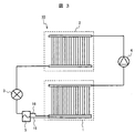
- FIG. 3 shows a schematic configuration of the heat pump system of the present embodiment.
- the heat pump system 10 includes a heat exchanger 1, a condenser 2, an expansion valve 3, a compressor 4, a gas-liquid separator 5, and the like.
- the condenser 2 recondenses the refrigerant by exchanging heat between an external working fluid such as air or water and the refrigerant compressed by the compressor 4.
- the recondensed refrigerant is sent to the expansion valve 3.
- the expansion valve 3 adiabatically expands the refrigerant recondensed by the condenser 2.
- the refrigerant adiabatically expanded becomes a gas-liquid two-phase flow and flows into the gas-liquid separator 5.
- the gas-liquid separator 5 the refrigerant is separated into liquid and gas and flows into the heat exchanger 1 through the liquid pipe 15 and the gas pipe 16.
- the gas-liquid separator 5 is disposed outside the heat exchanger 1.
- the present invention is not limited to this, and the gas-liquid separator 5 is disposed on the heat exchanger 1. It may be arranged inside. Moreover, you may attach the gas-liquid separator 5 to the inlet header 11 of FIG. Further, the gas-liquid separator 5 may be integrated with the inlet header 11 of FIG.
- the liquid refrigerant that has flowed into the heat exchanger 1 is evenly distributed to the plurality of heat transfer tubes 13, and then forms a slag flow with the gas refrigerant that has flowed from the holes 131 to exchange heat with high-temperature air. Then vaporize. Thereafter, the vaporized refrigerant joins again at the outlet header 12 and the outlet pipe 17, is compressed by the compressor 4, and then flows into the condenser 2 again.
- the refrigerant separated into the liquid and the gas by the gas-liquid separator 5 is separately put into the liquid reservoir 115 and the gas reservoir 116 of the heat exchanger 1, and is stored in each heat transfer tube 13. Refrigerant is sent evenly. For this reason, the heat exchanger tube 13 can be functioned without waste, and the efficiency of the heat exchanger 1 can be improved.
- a gas-liquid two-phase slag flow can be formed in the heat transfer tube 13 by reintroducing the gas refrigerant from the hole 131 of the heat transfer tube 13.
- the slag flow as compared with the liquid single-phase flow, evaporation occurs in a thin liquid film layer between the slag bubbles and the wall surface of the heat transfer tube 13, so that the heat transfer coefficient is increased. Therefore, heat from high-temperature air is efficiently transferred to the liquid refrigerant, and a heat exchanger with high heat transfer performance can be obtained.
- the tube diameter of the heat transfer tube 13 is small.
- the inner diameter is 1.0 mm or less. It is preferable to make it 0.5 mm or less.
- the hydraulic equivalent diameter may be 1.0 mm or less. Also in this case, it is more preferable that the thickness is 0.5 mm or less.
- the inner diameter of the circular tube and the hydraulic equivalent diameter other than the circular tube are both referred to as “inner diameter”.
- the lower limit of the tube diameter needs to be determined in consideration of these influences from the physical properties of the refrigerant used.
- the heat pump system 10 needs to determine the circulation amount of the refrigerant according to its capacity.
- the length of each heat transfer tube 13 shown in FIG. 1 is desirably 200 mm or less, and more desirably 100 mm or less, from the viewpoint of the pressure loss of the liquid refrigerant.
- FIG. 4 is a perspective view showing a heat exchanger according to the second embodiment.
- the present embodiment is different from the first embodiment in that gas / liquid separation is not performed before the refrigerant flows in, and the refrigerant flows into the heat exchanger 1 from the inlet pipe 18.
- the gas-liquid separator 5 of FIG. 3 is not used in this embodiment as shown in FIG.
- the internal structure of the inlet header 11 is as shown in FIG. Other configurations are the same as those of the first embodiment.
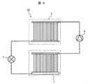
- FIG. 5 shows a configuration of the heat pump system 10 of the present embodiment.
- Example 1 As shown in this figure, the gas-liquid separator used in Example 1 is not used. For this reason, a refrigerant
- the operation of the heat pump system 10 in the present embodiment is as follows.
- the refrigerant whose pressure has been increased by the compressor 4 flows into the condenser 2, where it is condensed and liquefied.
- the liquid refrigerant is adiabatically expanded by the expansion valve 3 and becomes a gas-liquid two-phase flow. Thereafter, it flows into the heat exchanger 1.
- the refrigerant evaporated in the heat exchanger 1 is again pressurized by the compressor 4 and sent to the condenser 2.
- FIG. 6 shows the internal structure of the inlet header 11 of FIG.
- FIG. 6 is a cross-sectional view including the line segment AA ′ in FIG. 4 as viewed in the direction of the arrow. 6 indicates the direction of gravity, as in FIG.
- each heat transfer tube 13 is provided with a hole 131 in a portion where the gas refrigerant accumulates, so that the gas refrigerant flows into the heat transfer tube 13.
- the liquid refrigerant flowing into the inlet header 11 does not evaporate in the inlet header 11 and is accumulated in the inlet header 11.
- the surface is higher than the lower end of the heat transfer tube 13.
- the liquid refrigerant flows from the lower end portion of the heat transfer tube 13.
- the heat transfer tube 13 inside the inlet header 11 has a hole 131 (through hole) provided so that the gas refrigerant flows into the heat transfer tube 13, the gas refrigerant flows from the hole 131.
- the liquid refrigerant and gas refrigerant merge again. Thereby, a two-phase slag flow can be formed, and the heat transfer coefficient can be increased as compared with a liquid single-phase flow.
- the lower end of the heat transfer tube 13 is preferably closer to the bottom surface of the inlet header 11.
- the liquid refrigerant accumulated in the refrigerant reservoir 181 reaches the lower end of the heat transfer tube 13 at an early stage. Assuming that the inlet header 11 is installed horizontally, it is desirable that the lower end portions of all the heat transfer tubes 13 have the same height. Thereby, the liquid level of the liquid refrigerant accumulated in the refrigerant reservoir 181 reaches the lower ends of all the heat transfer tubes 13 almost simultaneously.
- the inlet pipe 18 does not penetrate into the inlet header 11, it is indicated by a broken line in order to clarify the connection position in the inlet header 11.
- the liquid level of the refrigerant is also indicated by a broken line.
- the volume of the refrigerant reservoir 181 is such that the refrigerant level is higher than the lower end of the heat transfer tube 13 and lower than the hole 131.
- the position of the lower end portion of the heat transfer tube 13 and the hole 131 is set sufficiently large.
- the inlet pipe 18 is connected to the upper part of the side part of the refrigerant reservoir 181. It is considered that the liquid refrigerant flowing from the inlet pipe 18 into the refrigerant storage unit 181 hardly disturbs the liquid level of the liquid refrigerant stored in the lower part of the refrigerant storage unit 181 when arranged in this way.
- a partition that serves as a baffle plate (not shown) is provided once for the liquid refrigerant flowing into the refrigerant reservoir 181 from the inlet pipe 18.
- the flow direction of the liquid refrigerant flowing from the inlet pipe 18 into the refrigerant reservoir 181 may be bent so that the liquid refrigerant meanders. In this case, even if the connection position of the inlet pipe 18 is not the upper part of the side surface part of the refrigerant storage part 181, the liquid level of the liquid refrigerant can be stabilized.
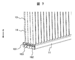
- Example 3 will be described with reference to FIGS.
- FIG. 7 is a partial perspective view showing the vicinity of the inlet header of the heat exchanger of the present embodiment.
- the cross section of the inlet header 11 inside the connection part of the inlet piping 18 of the inlet header 11 is shown so that the inside of the inlet header 11 can be understood.
- a convex portion 182 is provided below the refrigerant storage portion 181.
- the lower end portion of the heat transfer tube 13 is disposed below the upper surface portion of the convex portion 182. In other words, the lower end portion of the heat transfer tube 13 is inserted into the groove 183 between the convex portions 182.
- FIG. 8 is a partial cross-sectional view showing the bottom of the inlet header 11 in FIG. 7 (inside the inlet header 11).
- each of the convex portions 182 has a rectangular parallelepiped shape, and a lattice-like groove 183 is formed therebetween.
- the heat transfer tube 13 is disposed in the groove 183 between the convex portions 182 (in the drawing, the portion where the two grooves 183 intersect).
- the convex part 182 may be produced by casting together with the bottom part of the inlet header 11, or may be produced by press-molding a plate-like member. Press molding is desirable in that the inlet header 11 can be reduced in weight.
- the liquid level of the refrigerant can be maintained above the inlet of the heat transfer tube 13 even when the refrigerant is less than that in the second embodiment. Therefore, the amount of refrigerant sealed in the heat pump system 10 (FIG. 5) can be reduced.
- the present invention is not limited to the above-described embodiments, and includes various modifications. Further, a part of the configuration of one embodiment can be replaced with the configuration of another embodiment, and the configuration of another embodiment can be added to the configuration of one embodiment. Further, the above-described embodiments have been described in detail for easy understanding of the present invention, and are not necessarily limited to those having all the configurations described.
Landscapes
- Engineering & Computer Science (AREA)
- Physics & Mathematics (AREA)
- Thermal Sciences (AREA)
- Mechanical Engineering (AREA)
- General Engineering & Computer Science (AREA)
- Chemical & Material Sciences (AREA)
- Analytical Chemistry (AREA)
- Power Engineering (AREA)
- Details Of Heat-Exchange And Heat-Transfer (AREA)
- Heat-Exchange Devices With Radiators And Conduit Assemblies (AREA)
Abstract
La présente invention concerne un échangeur de chaleur comprenant un collecteur d'entrée, un collecteur de sortie et une pluralité de tubes de transfert thermique disposés entre ces collecteurs, l'intérieur d'un tube de transfert thermique étant un canal de réfrigérant, le fond du tube de transfert thermique est disposé à l'intérieur du collecteur d'entrée, et le tube de transfert thermique qui est à l'intérieur du collecteur d'entrée est pourvu d'un trou traversant de sorte que le réfrigérant gazeux puisse s'écouler à l'intérieur du tube de transfert thermique. De cette manière, un échangeur de chaleur comportant une pluralité de tubes de transfert thermique peut rendre le rapport gaz-liquide uniforme pour le réfrigérant devant être fourni et distribué vers chaque tube de transfert thermique et peut améliorer les propriétés de transfert thermique par formation d'un écoulement à deux phases au niveau de l'entrée du tube de transfert thermique.
Priority Applications (2)
| Application Number | Priority Date | Filing Date | Title |
|---|---|---|---|
| JP2018520670A JP6678235B2 (ja) | 2016-06-02 | 2017-03-13 | 熱交換器 |
| DE112017002266.5T DE112017002266T5 (de) | 2016-06-02 | 2017-03-13 | Wärmetauscher |
Applications Claiming Priority (2)
| Application Number | Priority Date | Filing Date | Title |
|---|---|---|---|
| JP2016110991 | 2016-06-02 | ||
| JP2016-110991 | 2016-06-02 |
Publications (1)
| Publication Number | Publication Date |
|---|---|
| WO2017208558A1 true WO2017208558A1 (fr) | 2017-12-07 |
Family
ID=60479277
Family Applications (1)
| Application Number | Title | Priority Date | Filing Date |
|---|---|---|---|
| PCT/JP2017/009897 Ceased WO2017208558A1 (fr) | 2016-06-02 | 2017-03-13 | Échangeur de chaleur |
Country Status (3)
| Country | Link |
|---|---|
| JP (1) | JP6678235B2 (fr) |
| DE (1) | DE112017002266T5 (fr) |
| WO (1) | WO2017208558A1 (fr) |
Cited By (4)
| Publication number | Priority date | Publication date | Assignee | Title |
|---|---|---|---|---|
| CN110285603A (zh) * | 2018-03-19 | 2019-09-27 | 松下知识产权经营株式会社 | 热交换器和使用其的制冷系统 |
| WO2020237960A1 (fr) * | 2019-05-31 | 2020-12-03 | 浙江三花智能控制股份有限公司 | Tuyau de distribution et échangeur de chaleur |
| JPWO2020230268A1 (ja) * | 2019-05-14 | 2021-11-11 | 三菱電機株式会社 | 熱交換器及び冷凍サイクル装置 |
| US12607411B2 (en) | 2020-09-23 | 2026-04-21 | Mitsubishi Electric Corporation | Heat exchanger and air-conditioning apparatus including heat exchanger |
Families Citing this family (1)
| Publication number | Priority date | Publication date | Assignee | Title |
|---|---|---|---|---|
| CN115371463B (zh) * | 2022-08-03 | 2024-11-15 | 西安交通大学 | 一种双排微通道换热器及其控制方法 |
Citations (6)
| Publication number | Priority date | Publication date | Assignee | Title |
|---|---|---|---|---|
| JPH10267468A (ja) * | 1997-03-25 | 1998-10-09 | Mitsubishi Electric Corp | 分配ヘッダー |
| JP2005172373A (ja) * | 2003-12-12 | 2005-06-30 | Calsonic Kansei Corp | 蒸発器 |
| JP2005299989A (ja) * | 2004-04-09 | 2005-10-27 | T Rad Co Ltd | 熱交換器用タンク |
| JP2009133567A (ja) * | 2007-11-30 | 2009-06-18 | Calsonic Kansei Corp | 気液分離器及び空気調和装置 |
| JP2014070860A (ja) * | 2012-10-01 | 2014-04-21 | Keihin Thermal Technology Corp | 熱交換器 |
| JP2016038115A (ja) * | 2014-08-05 | 2016-03-22 | サンデンホールディングス株式会社 | 熱交換器 |
Family Cites Families (2)
| Publication number | Priority date | Publication date | Assignee | Title |
|---|---|---|---|---|
| JPH0660661B2 (ja) | 1984-07-03 | 1994-08-10 | トヨタ自動車株式会社 | トルク変動吸収クラツチ |
| JP2001263861A (ja) | 2000-03-17 | 2001-09-26 | Sanyo Electric Co Ltd | 熱交換器 |
-
2017
- 2017-03-13 DE DE112017002266.5T patent/DE112017002266T5/de not_active Ceased
- 2017-03-13 JP JP2018520670A patent/JP6678235B2/ja not_active Expired - Fee Related
- 2017-03-13 WO PCT/JP2017/009897 patent/WO2017208558A1/fr not_active Ceased
Patent Citations (6)
| Publication number | Priority date | Publication date | Assignee | Title |
|---|---|---|---|---|
| JPH10267468A (ja) * | 1997-03-25 | 1998-10-09 | Mitsubishi Electric Corp | 分配ヘッダー |
| JP2005172373A (ja) * | 2003-12-12 | 2005-06-30 | Calsonic Kansei Corp | 蒸発器 |
| JP2005299989A (ja) * | 2004-04-09 | 2005-10-27 | T Rad Co Ltd | 熱交換器用タンク |
| JP2009133567A (ja) * | 2007-11-30 | 2009-06-18 | Calsonic Kansei Corp | 気液分離器及び空気調和装置 |
| JP2014070860A (ja) * | 2012-10-01 | 2014-04-21 | Keihin Thermal Technology Corp | 熱交換器 |
| JP2016038115A (ja) * | 2014-08-05 | 2016-03-22 | サンデンホールディングス株式会社 | 熱交換器 |
Cited By (6)
| Publication number | Priority date | Publication date | Assignee | Title |
|---|---|---|---|---|
| CN110285603A (zh) * | 2018-03-19 | 2019-09-27 | 松下知识产权经营株式会社 | 热交换器和使用其的制冷系统 |
| CN110285603B (zh) * | 2018-03-19 | 2021-12-24 | 松下知识产权经营株式会社 | 热交换器和使用其的制冷系统 |
| JPWO2020230268A1 (ja) * | 2019-05-14 | 2021-11-11 | 三菱電機株式会社 | 熱交換器及び冷凍サイクル装置 |
| JP7209821B2 (ja) | 2019-05-14 | 2023-01-20 | 三菱電機株式会社 | 熱交換器及び冷凍サイクル装置 |
| WO2020237960A1 (fr) * | 2019-05-31 | 2020-12-03 | 浙江三花智能控制股份有限公司 | Tuyau de distribution et échangeur de chaleur |
| US12607411B2 (en) | 2020-09-23 | 2026-04-21 | Mitsubishi Electric Corporation | Heat exchanger and air-conditioning apparatus including heat exchanger |
Also Published As
| Publication number | Publication date |
|---|---|
| JPWO2017208558A1 (ja) | 2019-02-21 |
| JP6678235B2 (ja) | 2020-04-08 |
| DE112017002266T5 (de) | 2019-01-24 |
Similar Documents
| Publication | Publication Date | Title |
|---|---|---|
| JP6678235B2 (ja) | 熱交換器 | |
| US10612856B2 (en) | Heat exchanger and air conditioning system | |
| US20150021003A1 (en) | Heat exchanger | |
| CN105247311B (zh) | 溢流式蒸发器内的侧装式制冷剂分配器和分配器的侧装式输入管道 | |
| CN105829822A (zh) | 制冷剂分配装置和冷却设备 | |
| CN106461339A (zh) | 蒸发器以及制冷机 | |
| CN105904960A (zh) | 冷却模块 | |
| CN109595960B (zh) | 热虹吸散热装置 | |
| JP2011142298A (ja) | 沸騰冷却装置 | |
| JP6747937B2 (ja) | 熱電発電システム | |
| WO2015045105A1 (fr) | Échangeur de chaleur et climatiseur l'utilisant | |
| CN103808180B (zh) | 热管冷却装置 | |
| JP2015092120A (ja) | 凝縮器 | |
| CN112584671A (zh) | 用于冷却电子构件的均温板 | |
| JPWO2017110740A1 (ja) | 放熱装置、それを用いた相変化冷却装置、および放熱方法 | |
| JP2018179325A (ja) | 熱交換器、および、それを用いたヒートポンプシステム | |
| WO2018051611A1 (fr) | Échangeur thermique et système de pompe à chaleur l'utilisant | |
| CN113758324A (zh) | 用于低压驱动器的回路式热管 | |
| JP2019024028A (ja) | 電子機器の冷却装置 | |
| CN107208980A (zh) | 具有卫星式蒸发器的环路热管 | |
| CN113716011B (zh) | 一种船舶用泵辅助冷却系统 | |
| CN223283271U (zh) | 一种高效能蒸发器 | |
| JP4930472B2 (ja) | 冷却装置 | |
| US11976854B2 (en) | Enhanced tube for direct expansion evaporators | |
| WO2012026221A1 (fr) | Dispositif de transport de chaleur de type en boucle |
Legal Events
| Date | Code | Title | Description |
|---|---|---|---|
| ENP | Entry into the national phase |
Ref document number: 2018520670 Country of ref document: JP Kind code of ref document: A |
|
| 121 | Ep: the epo has been informed by wipo that ep was designated in this application |
Ref document number: 17806120 Country of ref document: EP Kind code of ref document: A1 |
|
| 122 | Ep: pct application non-entry in european phase |
Ref document number: 17806120 Country of ref document: EP Kind code of ref document: A1 |