WO2017208652A1 - Dispositif de commande de moteur - Google Patents
Dispositif de commande de moteur Download PDFInfo
- Publication number
- WO2017208652A1 WO2017208652A1 PCT/JP2017/015607 JP2017015607W WO2017208652A1 WO 2017208652 A1 WO2017208652 A1 WO 2017208652A1 JP 2017015607 W JP2017015607 W JP 2017015607W WO 2017208652 A1 WO2017208652 A1 WO 2017208652A1
- Authority
- WO
- WIPO (PCT)
- Prior art keywords
- phase
- control device
- motor control
- command value
- motor
- Prior art date
- Legal status (The legal status is an assumption and is not a legal conclusion. Google has not performed a legal analysis and makes no representation as to the accuracy of the status listed.)
- Ceased
Links
Images


Classifications
-
- B—PERFORMING OPERATIONS; TRANSPORTING
- B60—VEHICLES IN GENERAL
- B60T—VEHICLE BRAKE CONTROL SYSTEMS OR PARTS THEREOF; BRAKE CONTROL SYSTEMS OR PARTS THEREOF, IN GENERAL; ARRANGEMENT OF BRAKING ELEMENTS ON VEHICLES IN GENERAL; PORTABLE DEVICES FOR PREVENTING UNWANTED MOVEMENT OF VEHICLES; VEHICLE MODIFICATIONS TO FACILITATE COOLING OF BRAKES
- B60T13/00—Transmitting braking action from initiating means to ultimate brake actuator with power assistance or drive; Brake systems incorporating such transmitting means, e.g. air-pressure brake systems
- B60T13/74—Transmitting braking action from initiating means to ultimate brake actuator with power assistance or drive; Brake systems incorporating such transmitting means, e.g. air-pressure brake systems with electrical assistance or drive
-
- B—PERFORMING OPERATIONS; TRANSPORTING
- B62—LAND VEHICLES FOR TRAVELLING OTHERWISE THAN ON RAILS
- B62D—MOTOR VEHICLES; TRAILERS
- B62D5/00—Power-assisted or power-driven steering
- B62D5/04—Power-assisted or power-driven steering electrical, e.g. using an electric servo-motor connected to, or forming part of, the steering gear
-
- B—PERFORMING OPERATIONS; TRANSPORTING
- B62—LAND VEHICLES FOR TRAVELLING OTHERWISE THAN ON RAILS
- B62D—MOTOR VEHICLES; TRAILERS
- B62D6/00—Arrangements for automatically controlling steering depending on driving conditions sensed and responded to, e.g. control circuits
-
- H—ELECTRICITY
- H02—GENERATION; CONVERSION OR DISTRIBUTION OF ELECTRIC POWER
- H02M—APPARATUS FOR CONVERSION BETWEEN AC AND AC, BETWEEN AC AND DC, OR BETWEEN DC AND DC, AND FOR USE WITH MAINS OR SIMILAR POWER SUPPLY SYSTEMS; CONVERSION OF DC OR AC INPUT POWER INTO SURGE OUTPUT POWER; CONTROL OR REGULATION THEREOF
- H02M7/00—Conversion of AC power input into DC power output; Conversion of DC power input into AC power output
- H02M7/42—Conversion of DC power input into AC power output without possibility of reversal
- H02M7/44—Conversion of DC power input into AC power output without possibility of reversal by static converters
- H02M7/48—Conversion of DC power input into AC power output without possibility of reversal by static converters using discharge tubes with control electrode or semiconductor devices with control electrode
-
- H—ELECTRICITY
- H02—GENERATION; CONVERSION OR DISTRIBUTION OF ELECTRIC POWER
- H02P—CONTROL OR REGULATION OF ELECTRIC MOTORS, ELECTRIC GENERATORS OR DYNAMO-ELECTRIC CONVERTERS; CONTROLLING TRANSFORMERS, REACTORS OR CHOKE COILS
- H02P21/00—Arrangements or methods for the control of electric machines by vector control, e.g. by control of field orientation
- H02P21/22—Current control, e.g. using a current control loop
Definitions
- the present invention relates to a motor control device that detects DC bus current and obtains current information on the AC side.
- This three-phase motor requires a current detector that detects a three-phase current that is passed through the stator.
- a phase current detector that detects a three-phase current of a three-phase motor is generally used.
- an automotive auxiliary system such as an electric control type brake system, electric power steering, electric oil pump, etc.
- a current detection means from a DC bus current flowing through a DC resistance provided for short circuit protection, a phase difference between power converters
- a DC bus current detection method is used in which a DC bus current value is sampled and a three-phase current is reproduced when a difference in switching timing occurs.
- Patent Document 1 the technique described in Patent Document 1 is known.
- one cycle of the triangular wave carrier signal for generating the PWM signal is divided into the first half period and the second half period, and the correction voltage value is added to the AC output voltage command value in the first half period to obtain the output voltage command value.
- the DC bus current is detected by increasing itself.
- the correction voltage value added in the first half period is subtracted so that the average output voltage does not fluctuate.
- the difference in switching timing is increased by increasing the difference in voltage command value between phases by adding and subtracting the correction voltage value. That is, in the present technology, the voltage command value is corrected so as to shift the phase of the phase voltage pulse.
- Patent Document 2 The technology described in Patent Document 2 is known for such noise problems.
- the switching frequency of the power converter in the region where the AC output voltage of the power converter is low, the switching frequency of the power converter is increased to remove it from the audible range, and in the region where the output voltage of the power converter is high, the switching frequency of the power converter. Is reduced to suppress the heat generation of the power converter.
- the present invention provides a motor control device that can reduce high-frequency noise associated with DC bus current detection without changing the switching frequency.
- a motor control device detects a three-phase current flowing in a three-phase motor based on a power converter, a three-phase motor driven by the power converter, and a DC bus current. And a control means for creating a phase voltage command value using the detected three-phase current and controlling the power converter using the phase voltage command value, the control means comprising a DC bus current At the time of detection, the phase voltage command value is corrected based on the d-axis voltage, and the phase of the phase voltage pulse is shifted.
- the current detection width when detecting the DC bus current is secured the current detection accuracy is improved, and the motor noise generated due to the phase shift of the phase voltage pulse for securing the current detection width is reduced. can do.
- the structure of the electrically controlled brake which is the 4th Embodiment of this invention is shown.
- the structure of the electric power steering which is the 5th Embodiment of this invention is shown.
- the structure of the pump drive system which is the 6th Embodiment of this invention is shown.
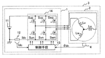
- FIG. 1 is a block diagram showing a configuration of a motor control apparatus according to a first embodiment of the present invention.
- the motor control device 3 includes a three-phase motor 2 and a controller 1 that drives the three-phase motor 2 by applying three-phase AC power to the three-phase motor 2.
- the controller 1 has a DC power source 11 and a power converter 14 that converts the DC power of the DC power source 11 into three-phase AC power and outputs it to the three-phase motor 2.
- a permanent magnet synchronous motor is applied as the three-phase motor 2.
- the power converter 14 constitutes a three-phase inverter circuit composed of six semiconductor switching elements (MOSFETs in FIG. 1). These six semiconductor switching elements are turned on / off by pulse width modulation signals Sup, Svp, Swp, Sun, Svn, and Swn output from the control means 13, thereby converting DC power into three-phase AC power.
- the control means 13 detects a three-phase AC current output from the power converter 14 based on a DC bus current detector 12, for example, a DC bus current Idc detected by a shunt resistor. Based on the detected three-phase alternating current, the control means 13 creates a pulse width modulation signal Sup, Svp, Swp, Sun, Svn, Swn.
- FIG. 2 is a functional block diagram showing the configuration of the control means 13 in FIG.
- the control unit 13 includes a three-phase current reproduction unit 131, a dq axis current conversion unit 132, a voltage command calculation unit 133, a coordinate conversion unit 134, a pulse width adjustment unit 135, and a drive signal generation unit 136. Is done. In the present embodiment, a so-called vector control technique is applied.
- the three-phase current reproduction unit 131 converts the DC bus current Idc detected by the current detector 12 (FIG. 1) into a three-phase current detection value Iuc using the pulse width modulation signals Sup, Svp, Swp, Sun, Svn, Swn. , Ivc, Iwc.
- the phase of the pulse width modulation signal is shifted in order to reliably detect a three-phase current.
- a known technique for example, see the above-mentioned Patent Document 1 is applied except for the phase shift means of the pulse width modulation signal.
- the dq-axis current conversion unit 132 uses the three-phase currents Iuc, Ivc, and Iwc, which are the outputs of the three-phase current reproduction unit 131, as the dq-axis in rotation coordinates using the rotor phase ⁇ dc of the three-phase motor 2 (FIG. 1). It converts into current detection values Idc and Iqc (DC amount) and outputs these detection values.
- the rotor phase ⁇ dc is detected by a position detector such as a resolver, or is estimated from the three-phase current and the three-phase voltage of the three-phase motor 2 without using a position detector, that is, using a known sensorless technique. To do. Further, the rotor phase ⁇ dc of the three-phase motor 2 may be estimated by applying a known technique for estimating the rotor phase based on the neutral point potential of the three-phase motor.
- the voltage command calculation unit 133 includes a difference between the d-axis current command value Id * and the d-axis current detection value Idc output from the dq-axis current conversion unit 132, the q-axis current command value Iq *, and the dq-axis current conversion unit.
- the d-axis voltage command value Vd * and the q-axis voltage command value Vq * that make these differences close to zero are created according to the difference from the q-axis current detection value Iqc output by 132.
- a d-axis voltage command value that brings the d-axis current difference closer to zero by proportional-integral (PI) control and a q-axis voltage command value that brings the q-axis current difference closer to zero. Is created.
- the d-axis current command value Id * and the q-axis current command value Iq * are not shown in a current command calculation unit, for example, a speed control unit or torque control for creating a current command for obtaining a desired motor speed or motor torque. Created by department.
- the coordinate conversion unit 134 uses the rotor phase ⁇ dc of the three-phase motor 2 to convert the d-axis voltage command value Vd and the q-axis voltage command value Vq output from the voltage command calculation unit 133 into a U-phase voltage command value Vu ′, It converts into V phase voltage command value Vv 'and W phase voltage command value Vw', and outputs these Vu ', Vv', and Vw '.
- the pulse width adjustment unit 135 inputs the phase voltage command values Vu ′, Vv ′, and Vw ′, and corrects Vu ′, Vv ′, and Vw ′ by a pulse width adjustment unit that will be described later so that a current detection width can be secured.
- the corrected U-phase voltage command value Vu, the corrected V-phase voltage command value Vv, and the corrected W-phase voltage command value Vw are output.
- the pulse width adjusting unit 135 generates a DC bus current that makes it difficult to detect the DC bus current because the current detection width is shortened when the pulse width modulation signal is generated based on the phase voltage command values Vu ′, Vv ′, and Vw ′.
- the phase voltage command values Vu ′, Vv ′, and Vw ′ are corrected in order to perform phase shift based on the d-axis voltage as will be described later.
- the pulse width adjustment unit 135 determines the magnitude relationship between the DC bus current detection time and the d-axis voltage of the phase voltage command values Vu ′, Vv ′, and Vw ′ at that time.
- the phase voltage command value having the maximum d-axis voltage and the phase voltage command value having the minimum d-axis voltage are corrected.
- the phase voltage command value in which the d-axis voltage has an intermediate magnitude is not substantially corrected.
- the drive signal generation unit 136 generates six pulse width modulation signals Sup, Svp, Swp, Sun, Svn, and Swn based on the corrected phase voltage command values Vu, Vv, and Vw output from the pulse width adjustment unit 135.
- a so-called PWM (Pulse Width Modulation) control technique is applied in which a pulse width modulation signal is created by comparing phase voltage command values Vu, Vv and Vw (modulation wave signals) with a carrier wave signal (for example, a triangular wave signal). Is done.
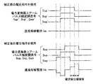
- FIG. 3 is a waveform example of a pulse width modulation signal showing the pulse width adjustment operation in the pulse width adjustment unit 135.
- the pulse width modulation signal Sup obtained by PWM control using the corrected U-phase voltage command value Vu is the pulse modulation of the U-phase upper arm obtained using the U-phase voltage command value Vu ′ before correction.
- the phase is shifted to the right side in the drawing, that is, in the delay direction.
- the pulse width modulation signal Swp obtained by PWM control using the corrected W-phase voltage command value Vw is the W-phase upper arm pulse modulation signal Swp obtained using the uncorrected W-phase voltage command value Vw ′.
- the phase is shifted to the left in the figure, that is, in the advance direction with respect to '.
- phase of the pulse width modulation signal Svp obtained by PWM control using the corrected V-phase voltage command value Vv is the pulse modulation of the V-phase upper arm obtained using the V-phase voltage command value Vv ′ before correction.
- the phase of the signal Svp ′ is the same and is not shifted. Due to such a phase shift, a DC bus current Idc flows as shown in FIG. 3, so that a three-phase current can be detected from the DC bus current.
- the pulse width adjustment unit 135 in the present embodiment applies a predetermined amount of correction voltage pulse to the phase voltage command value to shift the phase, and the voltage in the d-axis direction has little or no influence on the torque of the three-phase motor. (D-axis voltage).
- D-axis voltage the voltage in the d-axis direction has little or no influence on the torque of the three-phase motor.
- the three-phase current can be reliably detected based on the DC bus current, and the high-frequency noise accompanying the phase shift can be reduced.
- Such a pulse width adjustment unit 135 will be described below with reference to FIGS. First, the pulse width adjustment of the comparative example will be described, and then the pulse width adjustment of the present embodiment will be described.
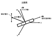
- FIG. 4 is a vector diagram showing the pulse width adjusting means in the comparative example.
- the direction of each phase voltage vector U, V, W of three phases (U phase, V phase, W phase), output voltage vector, correction voltage vector (dashed arrow), and d-axis (
- a magnet axis magnettic flux axis of the motor rotor (S, N)
- a q axis tilt axis
- the correction voltage vector (broken arrow) in the comparative example has a d-axis component and a q-axis component. For this reason, the correction of the phase voltage command value affects the torque of the three-phase motor 2, and noise is generated.
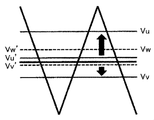
- FIG. 5 is a waveform diagram showing phase voltage command values before and after correction and a PWM carrier wave (triangular wave) in a comparative example.
- W-phase voltage command value Vw W-phase voltage command value
- the W-phase voltage command value Vw ′ (maximum phase) having the maximum size and the U-phase voltage command value Vu ′ (minimum size) having the minimum size among the three phases.
- a predetermined amount of correction phase voltage is added to or subtracted from each phase to obtain a U-phase voltage command value Vu and a W-phase voltage command value Vw after pulse width correction.
- the V-phase voltage command value Vv ′ (intermediate phase) having an intermediate magnitude is directly used as the V-phase voltage command value Vv after pulse width correction without correction.
- the magnitude of the voltage difference between the maximum phase (W phase) and the intermediate phase (V phase) and the magnitude of the voltage difference between the intermediate phase (V phase) and the minimum phase (U phase) are expanded.
- the maximum phase, the intermediate phase, and the minimum phase are the W phase, the V phase, and the U phase, respectively.
- a W phase (maximum phase) voltage pulse obtained by comparing a PWM carrier wave (triangular wave) with the W phase voltage command value Vw and the V phase voltage command value Vv
- a difference in switching timing of the V phase (intermediate phase) voltage pulse is obtained by comparing the PWM carrier wave (triangular wave) with the W phase (maximum phase) voltage command Vw ′ and the V phase (intermediate phase) voltage command Vv ′.
- the phase of the W-phase voltage pulse after voltage correction is shifted so as to be larger than the difference in switching timing between the W-phase voltage pulse and the V-phase (intermediate phase) voltage pulse.
- the phase of the U-phase (minimum phase) voltage pulse is also shifted.
- the current detection width is secured and the sampling accuracy of the DC bus current is improved, so that the three-phase current can be reliably detected based on the DC bus current.
- the correction voltage command has a q-axis component, motor noise is generated.
- FIG. 6 is a vector diagram showing the pulse width adjusting means in this embodiment. As in FIG. 4, the directions of the three-phase voltage vectors U, V, and W, the output voltage vector, the correction voltage vector (solid arrow), and the d-axis and q-axis in the rotating coordinate system are shown.
- the correction voltage vector (solid arrow) in this embodiment has only the d-axis component among the d-axis component and the q-axis component.
- the motor output is small and the rotation speed of the three-phase motor is low, that is, when the output voltage or motor speed of the power converter 14 (FIG. 1) is lower than the rated value and near zero, the torque of the d-axis voltage There is little impact on. For this reason, by correcting the d-axis voltage, it is possible to reduce motor noise that becomes more noticeable as the motor rotates at a lower speed.
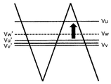
- FIG. 7 is a waveform diagram showing phase voltage command values and PWM carrier waves (triangular waves) before and after adjusting the pulse width in the present embodiment.
- the U-phase voltage command value Vu ′ before correction, the V-phase voltage command value Vv ′ and the W-phase voltage command value Vw ′, and the corrected U-phase voltage command value Vu, V phase voltage command value Vv and W phase voltage command value Vw are shown.
- the U-phase voltage command value Vu ′ having the largest d-axis direction component and the V-phase voltage command value Vv ′ having the smallest d-axis direction component are obtained. Then, a predetermined amount of corrected d-axis voltage is added or subtracted to obtain corrected U-phase voltage command value Vu and V-phase voltage command value Vv, respectively.
- the W-phase voltage command value Vw ′ having an intermediate d-axis direction component is directly used as the corrected W-phase voltage command value Vw without correction.
- the maximum phase, intermediate phase, and minimum phase before correction are the W phase, U phase, and V phase, respectively.
- the maximum phase, intermediate phase, and minimum phase after correction are respectively the U phase, W phase, and V phase.
- the maximum phase, the intermediate phase, and the minimum phase do not necessarily match before and after correction.
- the magnitude of the voltage difference between the maximum phase (before correction: W phase, after correction: U phase) and the intermediate phase (before correction: U phase, after correction: W phase), and the intermediate phase (before correction: U phase) , After correction: W phase) and the magnitude of the voltage difference between the minimum phase (before correction: V phase, after correction: V phase) is enlarged as in the comparative example.
- the PWM carrier wave (triangular wave), the corrected U-phase voltage command value Vu and the intermediate-phase W-phase voltage command value Vw as in the comparative example, The difference in switching timing between the U-phase voltage pulse and the W-phase voltage pulse obtained by comparing the PWM carrier wave (triangular wave), the maximum-phase phase voltage command value Vw ′, and the intermediate-phase U-phase voltage command value Vu ′.
- the phase of the U-phase voltage pulse after voltage correction is shifted so as to be larger than the difference in switching timing between the W-phase voltage pulse and the U-phase voltage pulse obtained by comparing the two.
- the phase of the V-phase voltage pulse is also shifted.
- the current detection width of the DC bus current is secured and the sampling accuracy of the DC bus current is improved, so that the three-phase current can be reliably detected based on the DC bus current. Further, as described above, in the present embodiment, since the correction voltage is only the d-axis component, motor noise can be reduced.
- FIG. 8 shows a configuration of the pulse width adjusting unit 135 in FIG. 1 in which the above-described pulse width adjusting means is used.
- the d-axis direction correction phase voltage determination unit 1352 Based on the rotor phase ⁇ dc, the d-axis direction correction phase voltage determination unit 1352 has a maximum d-axis voltage and a minimum d-axis voltage among the U phase, V phase, and W phase at the time of detecting the DC bus current. Select the phase.
- the pulse shift phase adjustment unit 1351 receives the voltage command values Vu ′, Vv ′, and Vw ′ created by the coordinate conversion unit 134 (FIG. 2), and among these phase voltage command values, the d-axis direction corrected phase voltage.
- the phase voltage command values of the phase with the maximum d axis voltage and the phase with the minimum d axis voltage selected by the determination unit 1352 are corrected and output as corrected voltage command values Vu, Vv, and Vw, including uncorrected voltage command values.
- the correction voltage is set in the pulse shift adjustment unit 1351 by the correction d-axis voltage setting unit 1353.
- the correction d-axis voltage setting unit 1353 stores in advance a correction voltage of the d-axis voltage for each phase voltage command value of the phase having the maximum d-axis voltage and the phase having the minimum d-axis voltage. Set the correction amount.
- the corrected d-axis voltage setting unit 1353 may create a corrected d-axis voltage according to the magnitude of the phase voltage command values Vu ′, Vv ′ and Vw ′ before correction and the voltage difference between the phases. Accordingly, when the current detection width can be secured without correcting Vu ′, Vv ′, and Vw ′, the correction amount can be set to zero.
- the current detection width is ensured in the DC bus current detection method, the current detection accuracy is improved, and the phase voltage pulse is generated in accordance with the phase shift for securing the current detection width. Motor noise can be reduced.
- the timing for correcting the phase voltage command value that is, the sampling timing for detecting the DC bus current, and the magnitude of the correction voltage are such that the average value of the phase voltage command value is substantially the same before and after the correction. Set as appropriate.
- FIG. 9 is a vector diagram showing the pulse width adjusting means in the second embodiment. As in FIG. 6, the directions of the three-phase voltage vectors U, V, and W, the output voltage vector, the correction voltage vector (solid arrow), and the d-axis and q-axis in the rotating coordinate system are shown.
- FIG. 10 is a waveform diagram showing voltage command values and PWM carrier waves (triangular waves) before and after correction in the present embodiment. 10, similarly to FIG. 7, the U-phase voltage command value Vu ′ before correction, the V-phase voltage command value Vv ′ and the W-phase voltage command value Vw ′, and the U-phase voltage command value Vu after correction, V phase voltage command value Vv and W phase voltage command value Vw are shown.
- the phase voltage command value is corrected, and the direction of the corrected voltage is set as the d-axis direction.
- the phase voltage command values for the U phase and the V phase are corrected.
- the second embodiment as shown in FIGS. 9 and 10, only the U phase is used. The phase voltage command value is corrected for.
- the d-axis direction correction phase voltage determination unit selects only one of the phase having the maximum or minimum d-axis voltage. Configured. For example, the d-axis direction correction phase voltage determination unit 1352 selects the phase having the largest voltage difference from the phase having the largest d-axis voltage and the phase having the middle d-axis voltage.
- FIG. 11 is a block diagram showing the configuration of the motor control apparatus according to the second embodiment. This configuration is the same as that of the first embodiment (FIG. 1) except for the position detector 4 that detects the rotor phase ⁇ dc.
- the U-phase current having the minimum d-axis voltage is harder to detect from the DC bus current than the other phase currents, but the rotor phase ⁇ dc detected by the position detector 4.
- the d-axis current command value (Id * , Iq * in FIG. 1) is coordinate-converted into a three-phase current command value, whereby the U-phase current with the minimum d-axis voltage can be obtained.
- the current detection width is ensured in the DC bus current detection method, the current detection accuracy is improved, and the phase shift of the phase voltage pulse for securing the current detection width is achieved. As a result, motor noise generated can be reduced.
- FIG. 12 is a vector diagram showing pulse width adjusting means in the motor control apparatus according to the third embodiment of the present invention. As in FIG. 6, the directions of the three-phase voltage vectors U, V, and W, the output voltage vector, the correction voltage vector (solid arrow), and the d-axis and q-axis in the rotating coordinate system are shown.
- the apparatus configuration of this embodiment is the same as that of the first embodiment (FIGS. 1 and 2) described above.
- the direction of the correction voltage in this embodiment is slightly inclined from the direction parallel to the d-axis unlike the first embodiment (FIG. 6). That is, the correction voltage set by the correction voltage setting unit 1353 (FIG. 8) described above has not only the d-axis component but also the q-axis component, although it is smaller than the d-axis component.
- the correction voltage has a q-axis component
- the magnitude thereof is smaller than the d-axis component. Therefore, as in the first embodiment, a current detection width is ensured in the DC bus current detection method. The current detection accuracy is improved, and the motor noise generated with the phase shift of the phase voltage pulse for securing the current detection width can be reduced.
- FIG. 13 shows the configuration of an electric brake device according to the fourth embodiment of the present invention.
- the three-phase motor 2 is driven based on the detection value of the operation amount detector 42A that detects the operation amount of the brake pedal 42.
- the three-phase motor 2 is controlled by any one of the motor control devices 3 in the first to third embodiments described above.
- the motor torque of the three-phase motor 2 is output to the transmission mechanism 46, whereby the piston 45 is propelled.
- a hydraulic pressure is generated in the master cylinder 43, and the hydraulic pressure is supplied to the wheel cylinders 44a to 44d.
- the braking members provided in the wheel cylinders 44a to 44d are pressed by the non-braking members that rotate with the wheels, so that a braking force corresponding to the operation of the brake pedal 42 is applied to the vehicle.
- FIG. 14 shows the configuration of an electric power steering system according to the fifth embodiment of the present invention.
- the rotational torque of the steering wheel 52 is detected by the torque sensor 53, and the controller 1 in the motor control device 3 drives the three-phase motor 2 in accordance with the detected rotational torque. Control.
- the motor torque generated by the three-phase motor 2 is output to the steering mechanism 55 via the steering assist mechanism 54.
- the tire 56 is steered by the steering mechanism 55 while the electric power steering 51 assists the steering force in accordance with the input of the steering wheel 52.
- noise and vibration generated by the three-phase motor 2 are transmitted to the driver via the steering wheel 52.
- the driver feels the vibration and noise of the three-phase motor 2 more strongly when the steering wheel 52 is slowly turning or when the steering wheel is fixed.
- vibration or noise generated by the electric power steering can be reduced.
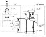
- FIG. 15 shows a configuration of an electric oil pump system according to the sixth embodiment of the present invention.
- the electric oil pump system of the present embodiment is used for transmission hydraulic pressure, brake hydraulic pressure, and the like inside an automobile.
- an oil pump 61 is attached to the three-phase motor 2 of the motor control device 3.
- the oil pump 61 controls the hydraulic pressure of the hydraulic circuit 62.
- the hydraulic circuit 62 includes a tank 63 that stores oil, a relief valve 64 that keeps the hydraulic pressure below a set value, a solenoid valve 65 that switches a hydraulic pressure transmission path in the hydraulic circuit 62, and a cylinder 66 that operates as a hydraulic actuator.
- the oil pump 61 is driven by the motor control device 3 to generate hydraulic pressure and drive a cylinder 66 that is a hydraulic actuator.
- the hydraulic pressure transmission path is switched by the solenoid valve 65, whereby the load of the oil pump 61 changes and a load disturbance occurs in the motor control device 3. For this reason, the three-phase motor 2 vibrates and generates noise.
- various motors capable of vector control can be applied as a three-phase motor.
- An IGBT (Insulated Gate Bipolar Transistor) or the like may be applied as a semiconductor switching element constituting the power converter.
Landscapes
- Engineering & Computer Science (AREA)
- Transportation (AREA)
- Mechanical Engineering (AREA)
- Power Engineering (AREA)
- Chemical & Material Sciences (AREA)
- Combustion & Propulsion (AREA)
- Control Of Ac Motors In General (AREA)
Abstract
L'invention concerne un dispositif de commande de moteur dont le bruit haute fréquence associé à la détection d'un courant de bus en courant continu peut être réduit sans modifier la fréquence de commutation. Le dispositif de commande de moteur (3) comprend : un convertisseur de puissance (14) ; un moteur triphasé (2) entraîné par le convertisseur de puissance ; et un moyen de commande (13) qui détecte un courant triphasé circulant à travers le moteur triphasé sur la base d'un courant de bus en courant continu, crée une valeur de commande de tension de phase à l'aide du courant triphasé détecté, et commande le convertisseur de puissance à l'aide de la valeur de commande de tension de phase. Au moment de la détection du courant de bus en courant continu, le moyen de commande corrige la valeur de commande de tension de phase sur la base d'une tension d'axe d, et décale la phase d'une impulsion de tension de phase.
Priority Applications (1)
| Application Number | Priority Date | Filing Date | Title |
|---|---|---|---|
| JP2018520705A JP6678739B2 (ja) | 2016-06-03 | 2017-04-18 | モータ制御装置 |
Applications Claiming Priority (2)
| Application Number | Priority Date | Filing Date | Title |
|---|---|---|---|
| JP2016111733 | 2016-06-03 | ||
| JP2016-111733 | 2016-06-03 |
Publications (1)
| Publication Number | Publication Date |
|---|---|
| WO2017208652A1 true WO2017208652A1 (fr) | 2017-12-07 |
Family
ID=60478282
Family Applications (1)
| Application Number | Title | Priority Date | Filing Date |
|---|---|---|---|
| PCT/JP2017/015607 Ceased WO2017208652A1 (fr) | 2016-06-03 | 2017-04-18 | Dispositif de commande de moteur |
Country Status (2)
| Country | Link |
|---|---|
| JP (1) | JP6678739B2 (fr) |
| WO (1) | WO2017208652A1 (fr) |
Cited By (3)
| Publication number | Priority date | Publication date | Assignee | Title |
|---|---|---|---|---|
| JP2020015468A (ja) * | 2018-07-27 | 2020-01-30 | 日立オートモティブシステムズ株式会社 | 電動ブレーキ装置 |
| JP2020182303A (ja) * | 2019-04-24 | 2020-11-05 | 株式会社デンソー | 回転電機の制御装置 |
| JP2023176997A (ja) * | 2022-06-01 | 2023-12-13 | 日産自動車株式会社 | モータ制御方法及びモータ制御装置 |
Families Citing this family (1)
| Publication number | Priority date | Publication date | Assignee | Title |
|---|---|---|---|---|
| US11465672B2 (en) * | 2020-04-21 | 2022-10-11 | Nsk Ltd. | Steering device |
Citations (3)
| Publication number | Priority date | Publication date | Assignee | Title |
|---|---|---|---|---|
| JP2010068653A (ja) * | 2008-09-11 | 2010-03-25 | Sanyo Electric Co Ltd | インバータ制御装置及びモータ駆動システム |
| JP2012178927A (ja) * | 2011-02-25 | 2012-09-13 | Sanyo Electric Co Ltd | インバータ制御装置 |
| WO2015025622A1 (fr) * | 2013-08-22 | 2015-02-26 | 日立オートモティブシステムズ株式会社 | Dispositif de commande de moteur électrique à courant alternatif, système d'entraînement de moteur électrique à courant alternatif, système de régulation de pression de fluide et système de positionnement |
Family Cites Families (3)
| Publication number | Priority date | Publication date | Assignee | Title |
|---|---|---|---|---|
| JP4643404B2 (ja) * | 2005-09-15 | 2011-03-02 | 三菱電機株式会社 | インバータ制御装置 |
| JP5968805B2 (ja) * | 2013-02-28 | 2016-08-10 | 日立オートモティブシステムズ株式会社 | モータ装置およびモータ駆動装置 |
| JP6298390B2 (ja) * | 2014-09-29 | 2018-03-20 | 日立オートモティブシステムズ株式会社 | 電動機駆動制御装置、電動パワーステアリング装置、電動ブレーキ装置、電動ポンプ装置 |
-
2017
- 2017-04-18 WO PCT/JP2017/015607 patent/WO2017208652A1/fr not_active Ceased
- 2017-04-18 JP JP2018520705A patent/JP6678739B2/ja active Active
Patent Citations (3)
| Publication number | Priority date | Publication date | Assignee | Title |
|---|---|---|---|---|
| JP2010068653A (ja) * | 2008-09-11 | 2010-03-25 | Sanyo Electric Co Ltd | インバータ制御装置及びモータ駆動システム |
| JP2012178927A (ja) * | 2011-02-25 | 2012-09-13 | Sanyo Electric Co Ltd | インバータ制御装置 |
| WO2015025622A1 (fr) * | 2013-08-22 | 2015-02-26 | 日立オートモティブシステムズ株式会社 | Dispositif de commande de moteur électrique à courant alternatif, système d'entraînement de moteur électrique à courant alternatif, système de régulation de pression de fluide et système de positionnement |
Cited By (6)
| Publication number | Priority date | Publication date | Assignee | Title |
|---|---|---|---|---|
| JP2020015468A (ja) * | 2018-07-27 | 2020-01-30 | 日立オートモティブシステムズ株式会社 | 電動ブレーキ装置 |
| JP7046751B2 (ja) | 2018-07-27 | 2022-04-04 | 日立Astemo株式会社 | 電動ブレーキ装置 |
| JP2020182303A (ja) * | 2019-04-24 | 2020-11-05 | 株式会社デンソー | 回転電機の制御装置 |
| JP7188265B2 (ja) | 2019-04-24 | 2022-12-13 | 株式会社デンソー | 回転電機の制御装置 |
| JP2023176997A (ja) * | 2022-06-01 | 2023-12-13 | 日産自動車株式会社 | モータ制御方法及びモータ制御装置 |
| JP7826843B2 (ja) | 2022-06-01 | 2026-03-10 | 日産自動車株式会社 | モータ制御方法及びモータ制御装置 |
Also Published As
| Publication number | Publication date |
|---|---|
| JPWO2017208652A1 (ja) | 2019-03-28 |
| JP6678739B2 (ja) | 2020-04-08 |
Similar Documents
| Publication | Publication Date | Title |
|---|---|---|
| EP2194643B1 (fr) | Contrôleur pour moteur électrique | |
| CN111418147B (zh) | 马达驱动系统 | |
| CN109463039B (zh) | 电动助力转向装置 | |
| JP7102407B2 (ja) | インバータ装置、及び、電動パワーステアリング装置 | |
| US9979340B2 (en) | Apparatus for controlling three phase rotary electric machine reducing peak value of phase current | |
| US20140253006A1 (en) | Power converter | |
| EP3641126A1 (fr) | Dispositif de commande de moteur et dispositif de direction assistée électrique le comportant | |
| JP4604820B2 (ja) | モータ駆動システムの制御装置 | |
| JP2001245498A (ja) | 同期モータ制御装置及びそれを用いた車両 | |
| WO2010116787A1 (fr) | Dispositif de commande de moteur électrique | |
| JP6512372B2 (ja) | 電動パワーステアリング装置 | |
| WO2012137300A1 (fr) | Appareil de commande pour moteur électrique, véhicule électrique équipé de ce moteur et procédé de commande du moteur électrique | |
| CN111213315B (zh) | 电动机控制装置以及制动控制装置 | |
| US10910974B2 (en) | Control device for AC motor | |
| JP6678739B2 (ja) | モータ制御装置 | |
| JP2017017962A (ja) | インバータの制御装置 | |
| JP5556219B2 (ja) | 電動パワーステアリング装置 | |
| JP7517205B2 (ja) | モータ制御装置、および、それを備えた電動パワーステアリング装置 | |
| JP2009136034A (ja) | モータ制御装置 | |
| JP2001197778A (ja) | 交流モータの制御装置 | |
| JP5412772B2 (ja) | 回転機の制御装置 | |
| JP7634807B2 (ja) | 回転機の制御装置及び電動パワーステアリング装置 | |
| JP2021022965A (ja) | 誘導電動機の駆動装置、駆動方法、および電気車 | |
| JP7046751B2 (ja) | 電動ブレーキ装置 | |
| WO2024069745A1 (fr) | Dispositif de commande d'onduleur |
Legal Events
| Date | Code | Title | Description |
|---|---|---|---|
| ENP | Entry into the national phase |
Ref document number: 2018520705 Country of ref document: JP Kind code of ref document: A |
|
| NENP | Non-entry into the national phase |
Ref country code: DE |
|
| 121 | Ep: the epo has been informed by wipo that ep was designated in this application |
Ref document number: 17806212 Country of ref document: EP Kind code of ref document: A1 |
|
| 122 | Ep: pct application non-entry in european phase |
Ref document number: 17806212 Country of ref document: EP Kind code of ref document: A1 |