WO2017208721A1 - Dispositif de traitement d'informations, dispositif de stockage optique, procédé de traitement d'informations, et programme - Google Patents
Dispositif de traitement d'informations, dispositif de stockage optique, procédé de traitement d'informations, et programme Download PDFInfo
- Publication number
- WO2017208721A1 WO2017208721A1 PCT/JP2017/017116 JP2017017116W WO2017208721A1 WO 2017208721 A1 WO2017208721 A1 WO 2017208721A1 JP 2017017116 W JP2017017116 W JP 2017017116W WO 2017208721 A1 WO2017208721 A1 WO 2017208721A1
- Authority
- WO
- WIPO (PCT)
- Prior art keywords
- signal
- adaptive
- equalization
- input
- output
- Prior art date
- Legal status (The legal status is an assumption and is not a legal conclusion. Google has not performed a legal analysis and makes no representation as to the accuracy of the status listed.)
- Ceased
Links
Images


Classifications
-
- G—PHYSICS
- G11—INFORMATION STORAGE
- G11B—INFORMATION STORAGE BASED ON RELATIVE MOVEMENT BETWEEN RECORD CARRIER AND TRANSDUCER
- G11B20/00—Signal processing not specific to the method of recording or reproducing; Circuits therefor
- G11B20/10—Digital recording or reproducing
- G11B20/10009—Improvement or modification of read or write signals
- G11B20/10046—Improvement or modification of read or write signals filtering or equalising, e.g. setting the tap weights of an FIR filter
-
- G—PHYSICS
- G11—INFORMATION STORAGE
- G11B—INFORMATION STORAGE BASED ON RELATIVE MOVEMENT BETWEEN RECORD CARRIER AND TRANSDUCER
- G11B20/00—Signal processing not specific to the method of recording or reproducing; Circuits therefor
- G11B20/10—Digital recording or reproducing
- G11B20/10009—Improvement or modification of read or write signals
- G11B20/10305—Improvement or modification of read or write signals signal quality assessment
- G11B20/10314—Improvement or modification of read or write signals signal quality assessment amplitude of the recorded or reproduced signal
-
- G—PHYSICS
- G11—INFORMATION STORAGE
- G11B—INFORMATION STORAGE BASED ON RELATIVE MOVEMENT BETWEEN RECORD CARRIER AND TRANSDUCER
- G11B7/00—Recording or reproducing by optical means, e.g. recording using a thermal beam of optical radiation by modifying optical properties or the physical structure, reproducing using an optical beam at lower power by sensing optical properties; Record carriers therefor
- G11B7/004—Recording, reproducing or erasing methods; Read, write or erase circuits therefor
- G11B7/005—Reproducing
-
- G—PHYSICS
- G11—INFORMATION STORAGE
- G11B—INFORMATION STORAGE BASED ON RELATIVE MOVEMENT BETWEEN RECORD CARRIER AND TRANSDUCER
- G11B7/00—Recording or reproducing by optical means, e.g. recording using a thermal beam of optical radiation by modifying optical properties or the physical structure, reproducing using an optical beam at lower power by sensing optical properties; Record carriers therefor
- G11B7/12—Heads, e.g. forming of the optical beam spot or modulation of the optical beam
- G11B7/13—Optical detectors therefor
- G11B7/133—Shape of individual detector elements
Definitions
- the present disclosure relates to an information processing device, an optical storage device, an information processing method, and a program. More specifically, the present invention relates to an information processing apparatus, an optical storage apparatus, an information processing method, and a program that realize high-quality data reproduction from a disk on which high-density data recording has been performed.
- optical disks such as DVD (Digital Versatile Disc) and BD (Blu-ray (registered trademark) Disc) are widely used.
- optical discs such as BDs are required to perform high-density information recording.
- a method of increasing the density of an optical disc there are a method of shortening a channel bit length, that is, a mark length and increasing the density in the linear density direction, and a method of narrowing a track pitch.
- Patent Document 1 Japanese Patent Application Laid-Open No. 2005-322367
- Patent Document 2 Japanese Patent Application Laid-Open No. 2002-183970
- Patent Document 3 Japanese Patent Application Laid-Open No. 2002-183970
- Patent Document 1 discloses a noise reduction processing configuration to which an analog division method is applied.
- Patent Document 2 discloses a noise reduction processing configuration based on an analog multiplication method.
- Patent Document 3 discloses a noise reduction processing configuration to which a transversal filter adaptive feedback method is applied.
- these conventional techniques have a problem in terms of the feasibility of a wideband analog multiplier circuit, a divider circuit, and a delay adjustment circuit for exhibiting a sufficient noise reduction effect.
- the present disclosure has been made in view of, for example, the above-described problems.
- an information processing apparatus and an optical storage that reduce laser noise included in a reproduction signal of an optical disc and realize acquisition of a high-quality reproduction signal.
- An object is to provide an apparatus, an information processing method, and a program.
- the first aspect of the present disclosure is: A photodetector that outputs a signal based on the reflected light from the disk with respect to the light emitted from the laser diode; A front monitor that outputs a reference signal based on light emitted from the laser diode; A data detection processing unit that inputs an output signal of the photodetector and generates a reproduction signal; The data detection processing unit A reproduction signal-adaptive adaptive equalizer that inputs an output signal of the photodetector and outputs an equalized signal by adaptive equalization processing based on the input signal; A laser noise adaptive equalizer that inputs a laser noise signal included in a reference signal output from the front monitor and outputs an equalized signal by an adaptive equalization process based on the input signal; An arithmetic unit for performing arithmetic processing between the output of the adaptive equalizer for reproduction signal and the output of the adaptive equalizer for laser noise; The information processing apparatus includes a signal identification unit that generates an identification signal based on the output of the arithmetic unit
- the second aspect of the present disclosure is: An information processing method executed in an information processing apparatus, A process in which the photodetector outputs a signal based on the reflected light from the disk with respect to the light emitted from the laser diode; A process in which a front monitor outputs a reference signal based on light emitted from the laser diode; A data detection processing unit inputs an output signal of the photodetector and executes data detection processing for generating a reproduction signal, In the data detection processing, the data detection processing unit, A process of generating a reproduction signal-corresponding equalization signal by an adaptive equalization process based on the output signal of the photodetector; A process of generating an equalization signal corresponding to a laser noise by an adaptive equalization process based on a laser noise signal included in a reference signal output from the front monitor; Arithmetic processing of the reproduction signal-corresponding equalization signal and the laser noise-corresponding equalization signal; In the information processing method for executing the identification signal generation processing based on the calculation processing result.
- the third aspect of the present disclosure is: A program for executing information processing in an information processing apparatus;
- the information processing apparatus includes: A photodetector that outputs a signal based on the reflected light from the disk with respect to the light emitted from the laser diode; A front monitor that outputs a reference signal based on light emitted from the laser diode; A data detection processing unit for executing a data detection process for generating a reproduction signal by inputting an output signal of the photodetector;
- the program is stored in the data detection processing unit.
- the program of the present disclosure is a program that can be provided by, for example, a storage medium or a communication medium provided in a computer-readable format to an information processing apparatus or a computer system that can execute various program codes.
- a program in a computer-readable format, processing corresponding to the program is realized on the information processing apparatus or the computer system.
- system is a logical set configuration of a plurality of devices, and is not limited to one in which the devices of each configuration are in the same casing.
- an apparatus and a method for generating a reproduction signal with reduced laser noise are realized. Specifically, a photodetector (PD) that irradiates a disk with laser light and outputs a signal based on light reflected from the disk, a front monitor that outputs a reference signal based on light emitted from the laser diode, and an output signal from the PD Is input to generate a reproduction signal.
- PD photodetector
- a data detection processing unit includes a reproduction signal adaptive equalizer that outputs an equalized signal by an adaptive equalization process based on a PD output signal, and a laser noise compatible adaptive equalizer that outputs an equalized signal by an adaptive equalization process based on a laser noise signal Then, a reproduction signal with reduced laser noise is generated based on the calculation result of the output of the adaptive equalizer corresponding to the reproduction signal and the output of the adaptive equalizer corresponding to the laser noise.
- a reproduction signal with reduced laser noise is generated based on the calculation result of the output of the adaptive equalizer corresponding to the reproduction signal and the output of the adaptive equalizer corresponding to the laser noise.
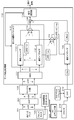
- FIG. 1 is a block diagram illustrating a configuration example of an information processing apparatus such as an optical storage apparatus that executes data reproduction processing and recording processing from an optical disc 10.
- the information processing apparatus includes an optical pickup 11 that records and reproduces information with respect to an optical disk 10 as an optical recording medium, and a spindle motor 12 that rotates the optical disk 10.
- a thread (feed motor) 13 is provided to move the optical pickup 11 in the radial direction of the optical disk 10.
- the optical disc 10 is a high-density optical disc such as a BD (Blu-ray (registered trademark) Disc).
- the BD is, for example, a high-density optical disc having a recording capacity of about 25 GB on a single layer on one side and about 50 GB on two layers on one side.
- the light source wavelength is set to 405 nm and the numerical aperture NA (Numerical Aperture) of the objective lens is increased to 0.85.
- NA numerical aperture
- the spot diameter can be reduced to 0.58 ⁇ m.
- the channel bit length that is, the mark length
- the density is increased in the linear density direction compared to BD (Blu-ray (registered trademark) Disc), and the capacity is increased to 100 GB for 3 layers and 128 GB for 4 layers.
- BDXL registered trademark
- a method for recording data on both the groove track and the land track is being adopted.
- a groove set along the recording track of the disk is a groove (G), and a track formed by the groove is called a groove track.
- an area that becomes a mountain portion sandwiched between two grooves (grooves) is a land (L), and a track formed by the land is called a land track.
- a high-density recording type disc data is recorded in both the groove (G) and the land (L). With this configuration, more data can be recorded on the disc.
- a high-density recording disk has a problem that the possibility of occurrence of crosstalk in data reproduction processing is increased. That is, there is a problem that crosstalk in which the data of the adjacent track is mixed as noise easily occurs in the read data of the read target track.
- the spindle motor 12 rotates at a constant linear velocity (CLV) or a constant angular velocity (CAV) during recording / reproduction.
- CLV constant linear velocity
- CAV constant angular velocity
- the mark information recorded on the track on the optical disk 10 is read by the optical pickup (optical head) 11.
- changes in brightness (reflectance) and reflection phase (complex reflectance) such as phase change marks or dye change marks are recorded on the tracks on the optical disk 10 by the optical pickup 11. As recorded.
- a recording mark by a phase change mark is recorded on a track formed by a wobbling groove.
- the phase change mark is an RLL (1, 7) PP modulation method (RLL; Run Length Limited, PP). : Parity preserve / Prohibit rmtr (repeated minimum transition runlength)), etc., in the case of 23.3 GB BD per layer, recorded at a linear density of 0.12 ⁇ m / bit, 0.08 ⁇ m / channel bit.
- the inner peripheral area of the optical disc 10 for example, physical information of the disc is recorded as embossed pits or wobbling grooves as reproduction-only management information. Reading of these pieces of information is also performed by the optical pickup 11. Further, the ADIP information embedded as wobbling of the groove track on the optical disc 10 is also read by the optical pickup 11.
- the optical pickup 11 includes a laser diode 51 serving as a laser light source, a laser driver 41 that supplies a driving current to the laser diode 51, a polarization beam splitter 53 that guides an optical path of light emitted from the laser diode 51 and reflected light from the disk 10. And a front monitor 42 for obtaining a monitoring signal (reference light) of the light emitted from the laser diode 51 and generating a feedback control signal for the laser driver 41. Further, a photodetector 56 for detecting reflected light from the disk 10, an objective lens serving as an output end of the laser light, and an optical for irradiating the disk recording surface with the laser light through the objective lens and guiding the reflected light to the photodetector. A system is constructed.
- the objective lens is held so as to be movable in the tracking direction and the focus direction by a biaxial mechanism.
- the entire optical pickup 11 can be moved in the radial direction of the disk by a thread mechanism 13.
- a drive current from the laser driver 41 is supplied to the laser diode of the optical pickup 11, and the laser diode generates a laser.
- the matrix circuit 14 includes a current-voltage conversion circuit, a matrix calculation / amplification circuit, and the like corresponding to output currents from a plurality of light receiving elements as photodetectors, and generates necessary signals by matrix calculation processing.
- a current-voltage conversion circuit may be formed in the photodetector element.
- a reproduction information signal (RF signal) corresponding to reproduction data, a focus error signal for servo control, a tracking error signal, and the like are generated.
- a push-pull signal is generated as a signal related to groove wobbling, that is, a signal for detecting wobbling.
- the reproduction information signal output from the matrix circuit 14 is supplied to the data detection processing unit 15, the focus error signal and the tracking error signal are supplied to the optical block servo circuit 21, and the push-pull signal is supplied to the wobble signal processing unit 16. .
- the data detection processing unit 15 performs binarization processing of the reproduction information signal. For example, the data detection processing unit 15 performs RF signal A / D conversion processing, PLL reproduction clock generation processing, PR (Partial Response) equalization processing, Viterbi decoding (maximum likelihood decoding), etc., and partial response maximum likelihood decoding processing A binary data string is obtained by (PRML detection method: Partial Response Maximum Likelihood detection method). The data detection processing unit 15 supplies a binary data string as information read from the optical disc 10 to the subsequent encoding / decoding unit 17.
- PRML detection method Partial Response Maximum Likelihood detection method
- the encoding / decoding unit 17 performs demodulation of reproduction data during reproduction and modulation processing of recording data during recording. That is, data demodulation, deinterleaving, ECC decoding, address decoding, etc. are performed during reproduction, and ECC encoding, interleaving, data modulation, etc. are performed during recording.
- the binary data string decoded by the data detection processing unit 15 is supplied to the encoding / decoding unit 17.
- the encoding / decoding unit 17 performs demodulation processing on the binary data string and obtains reproduction data from the optical disc 10. For example, a demodulating process for data recorded on the optical disk 10 that has been subjected to run-length limited code modulation such as RLL (1, 7) PP modulation and an ECC decoding process for error correction are performed. Get playback data.
- the data decoded to the reproduction data by the encoding / decoding unit 17 is transferred to the host interface 18 and transferred to the host device 30 based on an instruction from the system controller 20.
- the host device 30 is, for example, a computer device or an AV (Audio-Visual) system device.
- a clock synchronized with the push-pull signal is generated by the PLL processing.
- the wobble data is demodulated by the ADIP demodulation processing unit 26 into a data stream constituting an ADIP address and supplied to the address decoder 19.
- the address decoder 19 decodes the supplied data, obtains an address value, and supplies it to the system controller 20.
- recording data is transferred from the host device 30, and the recording data is supplied to the encoding / decoding unit 17 via the host interface 18.
- the encoding / decoding unit 17 performs error correction code addition (ECC encoding), interleaving, subcode addition, and the like as recording data encoding processing.
- ECC encoding error correction code addition
- the data subjected to these processes is subjected to run-length limited code modulation such as the RLL (1-7) PP method.
- the recording data processed by the encoding / decoding unit 17 is supplied to the write strategy unit 24.
- the write strategy unit 24 performs laser drive pulse waveform adjustment for recording layer characteristics, laser beam spot shape, recording linear velocity, and the like as recording compensation processing. Then, the laser drive pulse is output to the laser driver 41.
- the laser driver 41 Based on the laser driving pulse subjected to the recording compensation process, the laser driver 41 sends a current to the laser diode in the optical pickup 11 to emit laser light. As a result, a mark corresponding to the recording data is formed on the optical disc 10.
- the optical block servo circuit 21 generates various servo drive signals for focus, tracking, and thread from the focus error signal and tracking error signal from the matrix circuit 14 and executes the servo operation. That is, a focus drive signal and a tracking drive signal are generated according to the focus error signal and the tracking error signal, and the driver 28 drives the focus coil and tracking coil of the biaxial mechanism in the optical pickup 11.
- an optical pickup 11, a matrix circuit 14, an optical block servo circuit 21, a driver 28, a tracking servo loop and a focus servo loop by a biaxial mechanism are formed.
- the optical block servo circuit 21 turns off the tracking servo loop and outputs a jump drive signal in response to a track jump command from the system controller 20 to execute a track jump operation. Furthermore, the optical block servo circuit 21 generates a thread drive signal based on a thread error signal obtained as a low frequency component of the tracking error signal, access execution control from the system controller 20, and the like, and the thread driver 25 causes the thread mechanism 13. Drive.
- the spindle servo circuit 22 controls the spindle motor 12 to perform CLV rotation or CAV rotation.
- the spindle servo circuit 22 obtains the clock generated by the PLL for the wobble signal as the current rotational speed information of the spindle motor 12, and compares it with predetermined reference speed information to generate a spindle error signal.
- the spindle is compared by comparing this with predetermined reference speed information. An error signal is generated.
- the spindle servo circuit 22 outputs a spindle drive signal generated according to the spindle error signal, and causes the spindle driver 27 to execute CLV rotation or CAV rotation of the spindle motor 12.
- the spindle servo circuit 22 generates a spindle drive signal in response to a spindle kick / brake control signal from the system controller 20, and executes operations such as starting, stopping, acceleration, and deceleration of the spindle motor 12.
- a system controller 20 formed by a microcomputer.
- the system controller 20 executes various processes in accordance with commands from the host device 30 given via the host interface 18. For example, when a write command (write command) is issued from the host device 30, the system controller 20 first moves the optical pickup 11 to an address to be written. Then, the encoding / decoding unit 17 causes the encoding process to be performed on the data (for example, video data, audio data, etc.) transferred from the host device 30 as described above. Then, the laser driver 41 drives laser emission according to the encoded data, and recording is executed.
- a write command write command
- the system controller 20 first moves the optical pickup 11 to an address to be written.
- the encoding / decoding unit 17 causes the encoding process to be performed on the data (for example, video data, audio data, etc.) transferred from the host device 30 as described above.
- the laser driver 41 drives laser emission according to the encoded data, and recording is executed.
- the system controller 20 when a read command for requesting transfer of certain data recorded on the optical disc 10 is supplied from the host device 30, the system controller 20 first performs seek operation control for the instructed address. That is, a command is issued to the optical block servo circuit 21, and the access operation of the optical pickup 11 targeting the address specified by the seek command is executed. Thereafter, operation control necessary for transferring the data in the designated data section to the host device 30 is performed. That is, data is read from the optical disk 10 and reproduction processing in the data detection processing unit 15 and the encoding / decoding unit 17 is executed to transfer the requested data.
- FIG. 1 has been described as an optical disk device connected to the host device 30, the optical disk device may not be connected to other devices.
- an operation unit and a display unit are provided, and the configuration of the interface part for data input / output is different from that in FIG. That is, it is only necessary that recording and reproduction are performed in accordance with a user operation and a terminal unit for inputting / outputting various data is formed.
- various other examples of the configuration of the optical disc apparatus are conceivable.
- the optical pickup 11 records information on the optical disc 10 and reproduces information from the optical disc 10 using, for example, laser light (beam) having a wavelength ⁇ of 405 nm.
- the optical pickup 11 includes the laser diode 51 serving as a laser light source, the laser driver 41 that supplies a drive current to the laser diode 51, the light emitted from the laser diode 51, and the disk 10.
- a polarization beam splitter 53 that guides the optical path of the reflected light from the laser beam, a monitoring signal (reference light) of the light emitted from the laser diode 51, and a front monitor 42 that generates a feedback control signal for the laser driver 41.
- Laser light is emitted from a laser diode (LD) 51 that is a semiconductor laser.
- Laser light passes through a collimator lens 52, a polarizing beam splitter (PBS) 53, and an objective lens 54 and is irradiated onto the optical disk 10.
- the polarization beam splitter 53 has a separation surface that transmits approximately 100% of P-polarized light and reflects approximately 100% of S-polarized light.
- the reflected light from the recording layer of the optical disc 10 returns along the same optical path and enters the polarization beam splitter 53.
- the incident laser light is reflected by the polarization beam splitter 53 by approximately 100%.
- the laser beam reflected by the polarization beam splitter 53 is condensed on the light receiving surface of the photodetector 56 via the lens 55.
- the photodetector 56 has a light receiving cell for photoelectrically converting incident light on the light receiving surface.
- FIG. 2 shows the following three types of examples.
- A 1 signal output type without division
- B 3 signal output type corresponding to divided area
- C 5 signal output type corresponding to divided area
- the non-division 1-signal output type outputs one electrical signal corresponding to the amount of light received by the light receiving cells on the entire surface of the photodetector 56.
- the three-region output type corresponding to the divided region is constituted by a light receiving cell in which the light receiving surface of the photodetector 56 is divided, and outputs three electric signals corresponding to the amount of light received by the light receiving cell in each divided region.
- the five-signal output type corresponding to the divided area is also constituted by light receiving cells in which the light receiving surface of the photodetector 56 is divided, and outputs five electric signals corresponding to the amount of light received by the light receiving cells in each divided area.
- the three-signal output type corresponding to the divided area and the (C) five-signal output type light receiving cell corresponding to the divided area are divided lines extending in the radial direction (disc radial direction) of the optical disc 10 or in the tangential direction (track direction). Is divided into a plurality of regions. These divided photodetectors 56 output a plurality of channels of electrical signals in accordance with the amount of light received in each region of the light receiving cell. In addition to these, various configurations are possible for the divided configuration.
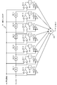
- FIG. 3 shows a detailed configuration of the (C) five-signal output type photodetector 56 corresponding to the divided area shown in FIG.
- the photodetector 56 includes a light receiving cell divided into a plurality of regions.
- A1, A2, B, C, D1, D2, D3, E1, E2, and E3 are divided into these areas.
- an electric signal corresponding to the amount of received light is individually output.
- signals applied to the generation of the reproduction signal are the following five signals corresponding to the five channels.
- Signal A A1 + A2 Signal
- B B
- Signal C C
- Signal D D1 + D2 + D3
- E E1 + E2 + E3
- a reproduction signal is generated using these five signals.
- region it is good also as a structure which produces
- A p * A1 + q * A2
- the output signal may be generated by multiplying the weighting factors p and q as described above.
- a high-quality reproduction signal can be obtained by performing an adaptive equalization process on each signal using a multi-input adaptive equalizer using such a split photodetector.
- An adaptive equalization processing configuration using a multi-input adaptive equalizer will be described later.
- Each of the signals A to E is a characteristic signal corresponding to the light receiving area, such as a signal containing a large amount of signal components of the track to be read or a signal having a high ratio of crosstalk signals of adjacent tracks.
- a reproduction signal generation processing configuration using such a split photodetector is disclosed in Patent Document 1 (International Publication WO2016 / 006157) which is an earlier application of the present applicant.
- the multiple-signal output type photo detector used in the present disclosure has the same configuration as those disclosed in these publications, and sets the multiple signals output from the photo detector and inputs each of the multiple signals to the multi-input adaptive equalizer.
- the configuration and processing for obtaining the equalized signal and the binarized signal are similarly applied to the present disclosure.
- the configuration of the optical pickup 11 shown in FIG. 2 shows the minimum components for explaining the present disclosure.
- the focus error signal and tracking output to the optical block servo circuit 21 via the matrix circuit 14 are shown.
- An error signal, a signal for generating a push-pull signal output to the wobble signal processing circuit 16 via the matrix circuit 14, and the like are omitted.
- various configurations other than the configuration shown in FIG. 2 are possible.
- the embodiment of the present disclosure described below will be described mainly as an example using the five-signal output type photodetector corresponding to the divided region described with reference to FIG. 3.
- the process of the present disclosure is not limited to the five-signal output type photodetector corresponding to the divided region described with reference to FIG. 3, but the one-signal output type without division, the three-signal output type corresponding to the divided region illustrated in FIG.
- the present invention can also be applied to a configuration using a photodetector having a different division configuration.
- the light beam of the return beam from the optical disc 10 is divided into a plurality of regions.
- Corresponding multiple channel reproduction information signals can be obtained.
- a high-quality reproduction signal can be obtained by data processing using the signals of these area units.
- a method for obtaining a reproduction information signal for each region a method other than the method of dividing the photodetector 56 can be used.
- an optical path conversion element for separating a plurality of regions is disposed in an optical path that passes through the objective lens 54 and reaches the photodetector 56, and a plurality of optical path conversion elements separated by the optical path conversion element are arranged. Any method that provides a beam to different photodetectors can be used.
- a diffraction element such as a holographic optical element, a refractive element such as a microlens array or a microprism, or the like can be used.
- the data detection processing unit 15 has an A / D converter 61 to which a reproduction information signal supplied from the matrix circuit 14 is supplied.
- FIG. 4 is a configuration example of the data detection processing unit 15 that inputs the five signals A to E obtained by using the divided-region-corresponding five-signal output type photo detector 56 shown in FIG. 3 and generates a reproduction signal. .
- a clock for the A / D converter 61 is formed by the PLL 62.
- the reproduction information signal supplied from the matrix circuit 14 is converted into digital data by the A / D converter 61.
- the digitized 5-channel reproduction information signals of the signals A to E are denoted by Sa to Se.
- a signal obtained by adding the reproduction information signals Sa to Se by the addition circuit 67 is supplied to the PLL 62.
- Signals A to E are electrical signals corresponding to the amounts of received light in the following areas described above with reference to FIG.
- Signal A A1 + A2
- B B
- Signal C C
- D D1 + D2 + D3
- E E1 + E2 + E3
- the data detection processing unit 15 includes a multi-input adaptive equalizer 63, a binarization detector 64, a PR (Partial Response) convolution unit 65, and an equalization error calculator 66.
- the multi-input adaptive equalizer 63 performs PR adaptive equalization processing based on the reproduction information signals Sa to Se.
- the reproduction information signals Sa to Se are output through the adaptive equalizer and equalized so that the added equalized signal y0 approximates a target PR waveform.
- the output of the multi-input adaptive equalizer may be used as a signal input to the PLL 62.
- the initial coefficient of the multi-input adaptive equalizer is set to a predetermined value.
- the binarization detector 64 is a Viterbi decoder, for example, and performs maximum likelihood decoding on the equalized signal y0 that has been PR-equalized to obtain binarized data DT.
- the binarized data DT is supplied to the encoding / decoding unit 17 shown in FIG. 1 to perform reproduction data demodulation processing.
- Viterbi decoding uses a Viterbi detector composed of a plurality of states configured in units of consecutive bits of a predetermined length and branches represented by transitions between them, and all possible bit sequences are used. A desired bit sequence is efficiently detected from the inside.
- the flow of the bit sequence leading to that state called the path memory register, the register that stores the partial response sequence and the signal path metric up to that state, called the path metric register, for each state
- the path metric register Two registers of the register for storing are prepared. Further, for each branch, there is prepared an arithmetic unit called a branch metric unit for calculating a partial response sequence and a signal path metric at the bit.
- various bit sequences can be associated in a one-to-one relationship by one of the paths passing through the state.
- the path metric between the partial response sequence that passes through these paths and the actual signal (reproduced signal) is the transition between the states that constitute the above path, that is, the branch metrics described above in the branch sequentially. It is obtained by adding.
- the PR convolution unit 65 performs a convolution process on the binarization result to generate a target signal Zk.
- This target signal Zk is an ideal signal without noise since it is a convolution of the binary detection result.
- PR (1, 2, 2, 2, 1) the value P for each channel clock is (1, 2, 2, 2, 1).
- the restraint length is 5.
- PR (1, 2, 3, 3, 3, 2, 1) the value P for each channel clock is (1, 2, 3, 3, 3, 2, 1).
- the restraint length is 7.
- the equalization error calculator 66 obtains an equalization error ek from the equalization signal y0 from the multi-input adaptive equalizer 63 and the target signal Zk, and this equalization error ek is supplied to the multi-input adaptive equalizer 63 for tap coefficient control. To supply. As shown in FIG. 7, the equalization error calculator 66 includes a subtracter 91 and a coefficient multiplier 92. The subtracter 81 subtracts the target signal Zk from the equalized signal y0. An equalization error ek is generated by multiplying the subtraction result by a predetermined coefficient a by the coefficient multiplier 82.
- the multi-input adaptive equalizer 63 includes adaptive equalizers 71 to 75 and an adder 76 as shown in FIG.
- the reproduction information signal Sa described above is input to the adaptive equalizer 71
- the reproduction information signal Sb is input to the adaptive equalizer 72
- the reproduction information signal Sc is input to the adaptive equalizer 73
- the reproduction information signal Sd is input to the adaptive equalizer 74
- the reproduction information signal Se is input to the adaptive equalizer 75.
- An adaptive equalizer is provided corresponding to the number of divided signals A to E obtained from the divided areas.
- the adaptive equalizers 71 to 75 include, for example, a LMSTVF (Least Means Square Transverse Filter) including a FIR (Finite Impulse Response) filter and a tap coefficient calculation unit that executes a tap coefficient update calculation process by the least square method.
- LMSTVF Local Means Square Transverse Filter
- FIR Finite Impulse Response
- Each of the adaptive equalizers 71 to 75 has parameters for the number of FIR (Finite Impulse Response) filter taps, the calculation accuracy (bit resolution), and the update gain of the adaptive calculation, and an optimum value is set for each.
- Each of the equalizers 71 to 75 is supplied with an equalization error ek as a coefficient control value for adaptive control.
- the outputs y1 to y5 of the adaptive equalizers 71 to 75 are added by the adder 76 and output as the equalized signal y0 of the multi-input adaptive equalizer 63.
- the output target of the multi-input adaptive equalizer 63 is an ideal PR waveform in which the binary detection result is convoluted with PR (partial response).
- the adaptive equalizer 71 is composed of, for example, an FIR filter as shown in FIG.
- the adaptive equalizer 71 is a filter having n + 1 stages of taps including delay elements 80-1 to 80-n, coefficient multipliers 81-0 to 81-n, and an adder 84.
- Coefficient multipliers 81-0 to 81-n respectively multiply tap coefficients C0 to Cn for the input x at each time point.
- the outputs of the coefficient multipliers 81-0 to 81-n are added by an adder 84 and taken out as an output y.
- the tap coefficients C0 to Cn are controlled.
- computing units 82-0 to 82-n that perform an operation by inputting an equalization error ek and each tap input.
- integrators 83-0 to 83-n for integrating the outputs of the respective computing units 82-0 to 82-n are provided.
- Each of the computing units 82-0 to 82-n performs, for example, computation of ⁇ 1 ⁇ ek ⁇ x.
- the outputs of the arithmetic units 82-0 to 82-n are integrated by the integrators 83-0 to 83-n, and the tap coefficients C0 to Cn of the coefficient multipliers 81-0 to 81-n are changed and controlled according to the integration results.
- the reason why the integrators 83-0 to 83-n are integrated is to adjust the response of the adaptive coefficient control.
- binarized data is decoded after unnecessary signals such as crosstalk are reduced.
- the other adaptive equalizers 72 to 75 shown in FIG. 5 have the same configuration as that of the adaptive equalizer 71.
- a common equalization error ek is supplied to the adaptive equalizers 71 to 75 to perform adaptive equalization. That is, the adaptive equalizers 71 to 75 optimize the error and phase distortion of the input signal frequency components of the reproduction information signals Sa, Sb, Sc, Sd, and Se, that is, perform adaptive PR equalization. That is, the tap coefficients C0 to Cn are adjusted according to the calculation result of ⁇ 1 ⁇ ek ⁇ x in the calculators 82-0 to 82-n. This means that the tap coefficients C0 to Cn are adjusted in the direction of eliminating the equalization error.
- the tap coefficients C0 to Cn are adaptively controlled using the equalization error ek in a direction in which the target frequency characteristics are obtained.
- the equalized signal y0 of the multi-input adaptive equalizer 63 obtained by adding the outputs y1, y2, y3, y4, and y5 of the adaptive equalizers 71 to 75 by the adder 76 is a signal with reduced crosstalk and the like.
- a specific example of tap coefficient control processing according to each signal A to E is described in the above-mentioned Patent Document 1 (International Publication WO2016 / 006157), which is a prior application of the same applicant as the present applicant. ing. Even in the configuration of the present application, the tap coefficient setting process corresponding to each signal similar to that described in the prior application can be applied.
- the laser light is irradiated from the optical pickup 11 and the reflected light component of the laser light is analyzed.
- noise included in the laser light itself irradiated by the optical pickup 11 that is, so-called laser noise, contributes to the deterioration of the quality of the reproduction signal.
- laser noise included in a reproduction signal is reduced and a high-quality reproduction signal can be generated will be described.
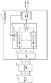
- FIG. 8 is a diagram showing a simplified configuration of the data detection processing unit 15 described above with reference to FIG.
- the optical pickup 101 is the optical pickup 101 in which the light receiving area is divided.
- the optical pickup 101 detects the reflected light from the optical disk of the irradiation laser light. Detection signals corresponding to the respective divided areas of the optical pickup 101 are supplied to the matrix circuit 102, and reproduction signals (n-channel reproduction signals) of a plurality of channels corresponding to the respective areas are obtained.
- the multi-channel playback signal (n-channel playback signal) is input to the A / D converter (ADC) 111 of the data detection processing unit 110, converted into a digital signal, and input to the multi-input adaptive equalizer 112.
- ADC A / D converter
- the multi-input adaptive equalizer 112 has n adaptive equalizers 112-1 to 112-n corresponding to each input signal (n-channel signal), and each channel signal is input to each of the adaptive equalizers 112-1 to 112-n.
- the adaptive equalizers 112-1 to 112-n have the FIR configuration described above with reference to FIG. 6, and are adaptively controlled using the equalization error ek so that the tap coefficients C0 to Cn become the target frequency characteristics.
- the outputs of the adaptive equalizers 121-1 to 121-n are added by the adder 113, and the equalized signal of the multi-input adaptive equalizer 112, which is the added signal, becomes a signal with reduced crosstalk and the like.
- the signal identification unit 114 illustrated in FIG. 8 includes the binarization detection unit 64, the PR convolution unit 65, and the equalization error calculator 66 illustrated in FIG.
- the processing in the data detection processing unit 110 illustrated in FIG. 8 can be executed under the control of a control unit including a CPU that executes a program stored in the storage unit of the information processing apparatus, for example.
- the configuration of the data detection processing unit 110 illustrated in FIG. 8 has an effect of reducing the crosstalk component from the adjacent track
- the configuration for performing the processing for reducing the laser noise included in the laser signal output from the optical pickup 110 is as follows. is not. Therefore, the output signal of the data detection processing unit 110 having the configuration shown in FIG. 8, that is, the binarized signal (binary signal) shown in FIG. 8 is a reproduction signal containing laser noise. In order to further improve the quality of the reproduction signal, it is necessary to remove or reduce the laser noise component.
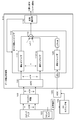
- FIG. 9 is a diagram showing a configuration example in which a configuration for reducing laser noise is added to the configuration of FIG. 8 described above as a basic configuration.
- the optical pickup 101, the matrix circuit 102, the A / D converter (ADC) 111 of the data detection unit 110, the multi-input adaptive equalizer 112, and the signal identification unit 114 are the same as those shown in FIG. It is a configuration.
- the optical pickup 101 is the optical pickup 101 in which the light receiving area is divided.
- the optical pickup 101 detects the reflected light from the optical disk of the irradiation laser light. Detection signals corresponding to the respective divided areas of the optical pickup 101 are supplied to the matrix circuit 102, and reproduction signals (n-channel reproduction signals) of a plurality of channels corresponding to the respective areas are obtained.
- the multi-channel playback signal (n-channel playback signal) is input to the A / D converter (ADC) 111 of the data detection processing unit 110, converted into a digital signal, and input to the multi-input adaptive equalizer 112.
- ADC A / D converter
- the multi-input adaptive equalizer 112 has n adaptive equalizers 112-1 to 112-n corresponding to each input signal (n-channel signal), and each channel signal is input to each of the adaptive equalizers 112-1 to 112-n.
- the adaptive equalizers 112-1 to 112-n are configured by, for example, a LMSTVF (Least Means Square Transversal Filter) including a FIR (Finite Impulse Response) filter and a tap coefficient calculation unit that executes a tap coefficient update calculation process by the least square method. Is done.
- LMSTVF Local Means Square Transversal Filter
- FIR Finite Impulse Response
- each of the adaptive equalizers 112-1 to 112-n has the FIR configuration described above with reference to FIG. 6, and the tap coefficients C0 to Cn have the target frequency characteristics using the equalization error ek. Is adaptively controlled.
- the outputs of the adaptive equalizers 121-1 to 121-n are added by the adder 113, and the equalized signal of the multi-input adaptive equalizer 112, which is the added signal, is input to the signal identification unit 114 via the subtractor 126.
- the equalized signal output from the multi-input adaptive equalizer 112 is a signal with reduced crosstalk and the like.
- the signal identification unit 114 shown in FIG. 9 includes the binarization detection unit 64, the PR convolution unit 65, and the equalization error calculator 66 shown in FIG.
- the signal discriminating unit 114 generates a binary signal for generating a final reproduction signal, and generates an equalization error signal that is fed back to the adaptive equalizer. These processes will be described later.
- FIG. 9 has the following configuration not shown in FIG. Front monitor 122, AC coupling unit 123, A / D converter (ADC) 124, Adaptive equalizer 125, Adder 121, Subtractor 126,
- the reproduction signal is generated based on the binarized signal (binary signal) output from the signal identification unit 114 shown in FIG.
- the front monitor 122 is a monitoring circuit for laser light that is configured in the optical pickup 101 and is output from a laser diode in the optical pickup 101.
- the front monitor 122 acquires a monitor signal of a laser signal (emitted light) output from the laser diode inside the optical pickup 101, and outputs a reference signal based on the emitted light from the laser diode.
- This monitor signal is the same component as the laser beam component irradiated on the optical disc 10 and is a laser beam including a noise component.
- the front monitor 122 outputs this monitor laser signal to the AC coupling unit 123.
- the AC coupling unit 123 separates a noise component and a DC component other than noise from the monitor laser signal, and extracts a noise signal from which the DC component has been removed.
- the noise component signal in the laser light extracted by the AC coupling unit 123 is input to the A / D converter (ADC) 124 of the data detection unit 110 and converted into a digital signal.
- ADC A / D converter
- the sampling frequency (fs2) of the ADC 124 that converts the laser noise signal into a digital signal is the sampling frequency (fs1) of the ADC 111 of the data detection processing unit 110 that converts the reproduction signal (n-channel reproduction signal) described above into a digital signal. ) It is preferable to set the frequency above. That is, fs2 ⁇ fs1 And This is a setting for reliably detecting and removing the laser noise signal contained in the reproduction signal.
- the laser noise signal (LNin) converted into a digital signal is input to the adaptive equalizer 125, and the adaptive equalizer 125 performs adaptive equalization processing and outputs an output signal (LNout).
- the input signal to the adaptive equalizer 125 is (LNin)
- the output from the adaptive equalizer 125 is (LNout).
- the adaptive equalizer 125 has the FIR configuration described above with reference to FIG. As described above with reference to FIG. 6, the adaptive equalizer uses the equalization error ek to adaptively control the tap coefficients C0 to Cn in the direction where the target frequency characteristic is obtained, and generates an output signal.
- the input LNin for the adaptive equalizer 125 shown in FIG. 9 corresponds to the input signal (xi) for the FIR configuration shown in FIG.
- the output LNout from the adaptive equalizer 125 corresponds to the output signal (yi) from the FIR configuration shown in FIG.
- the adaptive equalizer 125 shown in FIG. 9 inputs the addition signals ( ⁇ LMS-e1 to en) generated in the adder 121 as the equalization error signal (ek) having the configuration shown in FIG.
- the LMS-e1 to LMS-en signals are equalized error signals input to the adaptive equalizers 112-1 to 112-n that perform adaptive equalization processing of the n-channel signals of the optical pickup 101, that is, FIG. This corresponds to the equalization error (ek) shown in FIG.
- the adaptive equalizer 125 shown in FIG. 9 receives the equalization error signal addition signals ( ⁇ LMS-e1 to en) input to the adaptive equalizers 112-1 to 112-n and performs adaptive equalization. . That is, the adaptive equalizer 125 optimizes the error and phase distortion of the input laser noise signal (LNin) by adjusting the tap coefficient in the direction to eliminate the equalization error ( ⁇ LMS-e1 to en), that is, the adaptive PR. Equalization is performed to generate and output a laser noise output (LNout) close to a true noise component from which an error component included in the input laser noise signal (LNin) is excluded.
- LNout laser noise output
- the output signal (LNout) after adaptive equalization output from the adaptive equalizer 125 is a signal close to the true noise component in the laser light. This output signal (LNout) is input to the subtractor 126.
- the subtractor 126 outputs the output from the adaptive equalizer 125 from the addition value of the adaptive equalization signals that are the outputs of the adaptive equalizers 112-1 to 112-n that execute the adaptive equalization processing of the n-channel signals of the optical pickup 101. That is, a process of subtracting the noise signal (LNout) included in the laser light is executed. By this subtraction process, the laser noise component is subtracted from the adaptive equalization signal obtained as the reproduction signal, and the adaptive equalization signal with less noise is input to the signal identification unit 114.
- the signal identification unit 114 includes the binarization detection unit 64, the PR convolution unit 65, and the equalization error calculator 66 shown in FIG.
- the binarization detector 64 is a Viterbi decoder, for example, and performs maximum likelihood decoding on the PR equalized signal to generate binarized data.
- the binarized data is supplied to the encoding / decoding unit 17 shown in FIG. 1, and reproduction data demodulation processing is performed.
- Viterbi decoding uses a Viterbi detector composed of a plurality of states configured in units of consecutive bits of a predetermined length and branches represented by transitions between them, and all possible bit sequences are used. A desired bit sequence is efficiently detected from the inside.
- the PR convolution unit 65 performs a convolution process on the binarization result to generate a target signal Zk.
- the equalization error calculator 66 obtains an equalization error ek from the equalization signal y0 from the multi-input adaptive equalizer and the target signal Zk, and taps this equalization error ek to the multi-input adaptive equalizer 112 shown in FIG. Supply for coefficient control.
- the equalization error calculator 66 includes a subtractor 91 and a coefficient multiplier 92.
- the subtracter 81 subtracts the target signal Zk from the equalized signal y0.
- An equalization error ek is generated by multiplying the subtraction result by a predetermined coefficient a by the coefficient multiplier 82.
- the configuration of the first embodiment illustrated in FIG. 9 includes the adaptive equalizer 125 illustrated in FIG. 9 in order to obtain an accurate value of the laser noise included in the laser light output from the optical pickup 101.
- the adaptive equalizer 125 shown in FIG. 9 uses the equalization error signal input to the adaptive equalizers 112-1 to 112-n for executing the adaptive equalization processing of each signal of the n channel of the optical pickup 101, and performs adaptive equalization processing. Execute.
- the adaptive equalizer 125 adjusts the tap coefficient in the direction to eliminate the equalization error ( ⁇ LMS-e1 to en) to optimize the error and phase distortion of the input laser noise signal (LNin) and thereby correct the true noise component.
- a laser noise output (LNout) close to is generated.
- the output signal (LNout) after the adaptive equalization output from the adaptive equalizer 125 is subtracted from the addition value of the adaptive equalization signals output from the adaptive equalizers 112-1 to 112-n in the subtractor 126.
- the laser noise component is subtracted from the adaptive equalization signal obtained as the reproduction signal, and an adaptive equalization signal with less noise is generated.
- an equalization error signal with a reduced laser noise component is supplied to the adaptive equalizers 112-1 to 112-n that execute the adaptive equalization processing of each n-channel signal of the optical pickup 101.
- the adaptive equalization signal and the reproduction signal obtained in the above are high-quality reproduction signals with reduced laser noise components.
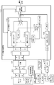
- FIG. 10 is also a diagram illustrating a configuration example in which a configuration for reducing laser noise is added based on the configuration of FIG. 8 described above as a basic configuration, similarly to FIG. 9.
- the optical pickup 101, the matrix circuit 102, the AD converter (ADC) 111 of the data detection unit 110, and the signal identification unit 114 are the same as the configuration illustrated in FIG.
- the optical pickup 101 is the optical pickup 101 in which the light receiving area is divided.
- the optical pickup 101 detects the reflected light from the optical disk of the irradiation laser light. Detection signals corresponding to the respective divided areas of the optical pickup 101 are supplied to the matrix circuit 102, and reproduction signals (n-channel reproduction signals) of a plurality of channels corresponding to the respective areas are obtained.
- the multi-channel playback signal (n-channel playback signal) is input to the A / D converter (ADC) 111 of the data detection processing unit 110, converted into a digital signal, and input to the multi-input adaptive equalizer 112.
- ADC A / D converter
- the multi-input adaptive equalizer 112 of the second embodiment receives each input signal (n channel signal) and performs n adaptive equalizers 112-1 to 112-n for performing adaptive equalization processing of each channel signal, and FIG.
- An adaptive equalizer 125 that performs an adaptive equalization process of laser noise similar to that described with reference to FIG.
- An input signal (Lnin) to the adaptive equalizer 125 is a signal generated via the front monitor 122, the AC coupling unit 123, and the A / D converter (ADC) 124, and is the same signal as described with reference to FIG. It is.
- the front monitor 122 is a monitoring circuit for laser light that is configured in the optical pickup 101 and is output from a laser diode in the optical pickup 101.
- the front monitor 122 acquires a monitor signal of a laser signal (emitted light) output from the laser diode inside the optical pickup 101, and outputs a reference signal based on the emitted light from the laser diode.
- This monitor signal is the same component as the laser beam component irradiated on the optical disc 10 and is a laser beam including a noise component.
- the front monitor 122 outputs this monitor laser signal to the AC coupling unit 123.
- the AC coupling unit 123 separates a noise component and a DC component other than noise from the monitor laser signal, and extracts a noise signal from which the DC component has been removed.
- the noise component signal in the laser light extracted by the AC coupling unit 123 is input to the A / D converter (ADC) 124 of the data detection unit 110 and converted into a digital signal.
- ADC A / D converter
- the sampling frequency (fs2) of the ADC 124 that converts the laser noise signal into a digital signal is preferably equal to or higher than the sampling frequency (fs1) of the ADC 111 corresponding to the reproduction signal (n-channel reproduction signal). That is, fs2 ⁇ fs1 And This is a setting for reliably detecting and removing the laser noise signal contained in the reproduction signal.
- a laser noise signal (LNin) converted into a digital signal is input to the adaptive equalizer 125.
- the adaptive equalizer 125 performs adaptive equalization processing on the input signal (LNin) and outputs an output signal (LNout).
- the adaptive equalizers 112-1 to 112-n that perform adaptive equalization processing for each channel signal corresponding to the read signal of the pickup 101 and the adaptive equalizer 125 that performs adaptive equalization processing for laser noise (LNin) are both, for example, , An FIR (Finite Impulse Response) filter and a LMSTVF (Least Means Square Transversal Filter) provided with a tap coefficient calculation unit that executes a tap coefficient update calculation process by the least square method.
- An FIR Finite Impulse Response
- LMSTVF Least Means Square Transversal Filter
- the outputs of the adaptive equalizers 121-1 to 121-n and the output of the adaptive equalizer 125 are added by the adder 113, and this added signal is input to the signal identification unit 114.
- 10 is configured to include the binarization detection unit 64, the PR convolution unit 65, and the equalization error calculator 66 shown in FIG.
- the signal discriminating unit 114 generates a binary signal for generating a final reproduction signal, and generates an equalization error signal that is fed back to the adaptive equalizer.
- the binarization detector 64 is a Viterbi decoder, for example, and performs maximum likelihood decoding on the PR equalized signal to generate binarized data.
- the binarized data is supplied to the encoding / decoding unit 17 shown in FIG. 1, and reproduction data demodulation processing is performed.
- Viterbi decoding uses a Viterbi detector composed of a plurality of states configured in units of consecutive bits of a predetermined length and branches represented by transitions between them, and all possible bit sequences are used. A desired bit sequence is efficiently detected from the inside.
- the PR convolution unit 65 performs a convolution process on the binarization result to generate a target signal Zk.
- the equalization error calculator 66 obtains an equalization error ek from the equalization signal y0 from the multi-input adaptive equalizer and the target signal Zk, and this equalization error ek is applied to the multi-input adaptive equalizer 112 shown in FIG. Supplied for control.
- the equalization error calculator 66 includes a subtractor 91 and a coefficient multiplier 92.
- the subtracter 81 subtracts the target signal Zk from the equalized signal y0.
- An equalization error ek is generated by multiplying the subtraction result by a predetermined coefficient a by the coefficient multiplier 82.
- the adaptive equalizers 112-1 to 112-n that execute adaptive equalization processing of each channel signal that is an element of the reproduction signal and the adaptive equalizer 125 that performs laser noise adaptive equalization processing are configured in parallel. ing. That is, the adaptive equalizers 121-1 to 121-n and the adaptive equalizer 125 shown in FIG. 10 are all equalized error signals (see FIG. 7) generated by the equalization error calculator (see FIG. 7) set in the signal identifying unit 114. ek) is input to perform adaptive equalization processing.
- Each of the adaptive equalizers 112-1 to n, 125 is composed of, for example, the FIR filter as shown in FIG. That is, as shown in FIG. 6, each adaptive equalizer 112-1 to n, 125 is an n + 1 stage tap having delay elements 80-1 to 80-n, coefficient multipliers 81-0 to 81-n, and an adder 84.
- tap coefficients C0 to Cn are multiplied for the input x at each time point, respectively.
- Outputs of the coefficient multipliers 81-0 to 81-n are added by an adder 84 to become an output y.
- the tap coefficients C0 to Cn are controlled.
- computing units 82-0 to 82-n that perform an operation by inputting an equalization error ek and each tap input.
- integrators 83-0 to 83-n for integrating the outputs of the respective computing units 82-0 to 82-n are provided.
- each of the calculators 82-0 to 82-n for example, calculation of ⁇ 1 ⁇ ek ⁇ x is performed.
- the outputs of the arithmetic units 82-0 to 82-n are integrated by the integrators 83-0 to 83-n, and the tap coefficients C0 to Cn of the coefficient multipliers 81-0 to 81-n are changed and controlled according to the integration results.
- the reason why the integrators 83-0 to 83-n are integrated is to adjust the response of the adaptive coefficient control. Using the above configuration, the binarized data is decoded after crosstalk cancellation and laser noise reduction processing are performed.
- Each of the adaptive equalizers 112-1 to n, 125 has the configuration shown in FIG. 6, and the same equalization error ek is supplied to perform adaptive equalization.
- the adaptive equalizers 112-1 to 112-n to which the channel signal corresponding to the reproduction signal is input optimizes the error and phase distortion of the input signal frequency component of the reproduction channel signal, that is, performs adaptive PR equalization. This is the same as a normal adaptive equalizer. That is, tap coefficients C0 to Cn are adjusted according to the calculation result of ⁇ 1 ⁇ ek ⁇ x in each of the calculators 82-0 to 82-n shown in FIG. 6, and taps are performed in a direction to eliminate equalization errors. The coefficients C0 to Cn are adjusted.
- the adaptive equalizer 125 that inputs laser noise (LNin)
- the output target is uncorrelated with the reproduction signal.
- the adaptive equalizer 125 performs an operation to cancel the correlation component, that is, the laser noise component. That is, in the case of the adaptive equalizer 125, the tap coefficients C0 to Cn are adjusted according to the calculation result of ⁇ 1 ⁇ ek ⁇ x in each of the calculators 82-0 to 82-n, and the addition result of the adder 113 in FIG.
- the tap coefficients C0 to Cn are adjusted so that the frequency characteristics in the direction of eliminating the noise component can be obtained.
- the tap coefficients C0 to Cn are adaptively controlled using the equalization error ek in the direction of the target frequency characteristics, while in the adaptive equalizer 125, the equalization error is also the same.
- the tap coefficients C0 to Cn are automatically controlled using ek in a direction that provides frequency characteristics effective for laser noise reduction.
- the multi-input adaptive equalizer 112 has a configuration in which an adaptive equalizer corresponding to each channel of a reproduction signal and an adaptive equalizer corresponding to laser noise are provided in parallel.
- the adaptive coefficient corresponding to the reproduction signal adaptively controls the tap coefficients C0 to Cn in the direction of the target frequency characteristic, and the adaptive equalizer 125 corresponding to the laser noise.
- the tap coefficients C0 to Cn are controlled in a direction that provides frequency characteristics that reduce laser noise.
- FIG. 11 is a diagram for explaining the configuration of this embodiment.
- the configuration shown in FIG. 11 is a diagram in which the configuration shown in FIG. 9 described above as the first embodiment is changed to a configuration that performs 2T sampling.
- recording is performed at a density corresponding to the channel bit length according to the disc type.
- the channel clock period is “T”
- the mark length is 2T to 8T.
- FIG. 11 is a diagram illustrating a detailed configuration in the case where the configuration illustrated in FIG. 9 described as the first embodiment is configured to perform 2T sampling.
- AAF Anti-alias filter
- DFF Digital flip-flop
- FIR filter 214 FIR filter 214
- DFF Digital flip-flop
- the anti-alias filter (AAF) 201 is a filter for limiting input signals to the adaptive equalizers 112-1 to 112-n to reproduced signals having a mark length of 2T or more.
- the optical pickup 101 is the optical pickup 101 in which the light receiving area is divided.
- the optical pickup 101 detects the reflected light from the optical disk of the irradiation laser light.
- a detection signal corresponding to each divided area of the optical pickup 101 is input to the anti-alias filter (AAF) 201.
- the anti-alias filter (AAF) 201 functions as a noise removal filter that removes a signal having a mark length of 2T or less as noise.
- the output of the anti-alias filter (AAF) 201 is a reproduction signal having a mark length of 2T or more, that is, a 2T sampling reproduction signal.
- the 2T sampling reproduction signal is supplied to the matrix circuit 102, and a plurality of channels of reproduction signals (n-channel reproduction signals) corresponding to each region are obtained.
- the multi-channel reproduction signal (n-channel reproduction signal) generated by the matrix circuit 102 is input to the A / D converter (ADC) 111 of the data detection processing unit 110, converted into a digital signal, and input to the multi-input adaptive equalizer 112.
- ADC A / D converter
- the multi-input adaptive equalizer 112 has n adaptive equalizers 112-1 to 112-n corresponding to each input signal (n-channel signal), and each channel signal is input to each of the adaptive equalizers 112-1 to 112-n.
- the adaptive equalizers 112-1 to 112-n are configured by, for example, a LMSTVF (Least Means Square Transversal Filter) including a FIR (Finite Impulse Response) filter and a tap coefficient calculation unit that executes a tap coefficient update calculation process by the least square method. Is done.
- LMSTVF Local Means Square Transversal Filter
- FIR Finite Impulse Response
- each of the adaptive equalizers 112-1 to 112-n has the FIR configuration described above with reference to FIG. 6, and the tap coefficients C0 to Cn have the target frequency characteristics using the equalization error ek. Is adaptively controlled.
- the outputs of the adaptive equalizers 121-1 to 121-n are added by the adder 113, and the equalized signal of the multi-input adaptive equalizer 112, which is the added signal, is input to the signal identification unit 114 via the subtractor 126.
- the equalized signal output from the multi-input adaptive equalizer 112 is a signal with reduced crosstalk and the like.
- the 11 includes the binarization detection unit 64, the PR convolution unit 65, and the equalization error calculator 66 shown in FIG.
- the signal discriminating unit 114 generates a binary signal for generating a final reproduction signal, and generates an equalization error signal that is fed back to the adaptive equalizer. These processes will be described later.
- the front monitor 122 is a monitoring circuit for laser light that is configured in the optical pickup 101 and is output from a laser diode in the optical pickup 101.
- the front monitor 122 acquires a monitor signal of a laser signal (emitted light) output from the laser diode inside the optical pickup 101, and outputs a reference signal based on the emitted light from the laser diode.
- This monitor signal is the same component as the laser beam component irradiated on the optical disc 10 and is a laser beam including a noise component.
- the AC coupling unit 123 separates the noise component and the DC component other than the noise, and extracts the noise signal from which the DC component is removed.
- the noise component signal in the laser light extracted by the AC coupling unit 123 is input to the slicer 212.
- the slicer 212 generates a binary signal to which a predetermined threshold is applied. That is, digital signal generation processing is performed.
- the laser noise binary signal generated by the slicer 212 is input to the adaptive equalizer 125 via the digital flip-flop (DFF) 213, the FIR filter 214, and the digital flip-flop (DFF) 215.
- the digital flip-flop (DFF) 213 executes sampling processing by 1T sampling of the laser noise binary signal generated by the slicer 212.
- the FIR filter 214 performs a filtering process on the 1T sampling signal generated by the DFF 213 and performs a smoothing process on the sampling data. For example, a smoothing process is executed by a finite impulse response filtering process in which the number of filters (1, 2, 1) is set. Further, the 1T sampling smoothed laser noise signal generated by the FIR filter 214 is input to a digital flip-flop (DFF) 215.
- DFF digital flip-flop
- the digital flip-flop (DFF) 215 executes 2T sampling processing on the 1T sampling smoothed laser noise signal generated by the FIR filter 214. That is, with these configurations, a 2T sampling laser noise signal (LNin) corresponding to the 2T sampling reproduction signal is generated and input to the adaptive equalizer 125.
- LNin 2T sampling laser noise signal
- the adaptive equalizer 125 performs adaptive equalization processing and outputs an output signal (LNout).
- the adaptive equalizer 125 has the FIR configuration described above with reference to FIG.
- the adaptive equalizer uses the equalization error ek to adaptively control the tap coefficients C0 to Cn in the direction where the target frequency characteristic is obtained, and generates an output signal.
- the input LNin for the adaptive equalizer 125 shown in FIG. 11 corresponds to the input signal (xi) for the FIR configuration shown in FIG.
- the output LNout from the adaptive equalizer 125 corresponds to the output signal (yi) from the FIR configuration shown in FIG.
- the adaptive equalizer 125 shown in FIG. 11 inputs the addition signals ( ⁇ LMS-e1 to en) generated in the adder 121 as the equalization error signal (ek) having the configuration shown in FIG.
- the LMS-e1 to LMS-en signals are equalized error signals input to the adaptive equalizers 112-1 to 112-n that perform adaptive equalization processing of the n-channel signals of the optical pickup 101, that is, FIG. This corresponds to the equalization error (ek) shown in FIG.
- the adaptive equalizer 125 shown in FIG. 11 receives the equalization error signal addition signals ( ⁇ LMS-e1 to en) input to the adaptive equalizers 112-1 to 112-n and performs adaptive equalization. . That is, the adaptive equalizer 125 optimizes the error and phase distortion of the input laser noise signal (LNin) by adjusting the tap coefficient in the direction to eliminate the equalization error ( ⁇ LMS-e1 to en), that is, the adaptive PR. Equalization is performed to generate and output a laser noise output (LNout) close to a true noise component from which an error component included in the input laser noise signal (LNin) is excluded.
- LNout laser noise output
- the output signal (LNout) after adaptive equalization output from the adaptive equalizer 125 is a signal close to the true noise component in the laser light. This output signal (LNout) is input to the subtractor 126.
- the subtractor 126 outputs the output from the adaptive equalizer 125 from the addition value of the adaptive equalization signals that are the outputs of the adaptive equalizers 112-1 to 112-n that execute the adaptive equalization processing of the n-channel signals of the optical pickup 101. That is, a process of subtracting the noise signal (LNout) included in the laser light is executed. By this subtraction process, the laser noise component is subtracted from the adaptive equalization signal obtained as the reproduction signal, and the adaptive equalization signal with less noise is input to the signal identification unit 114.
- the signal identification unit 114 includes the binarization detection unit 64, the PR convolution unit 65, and the equalization error calculator 66 shown in FIG.
- the binarization detector 64 is a Viterbi decoder, for example, and performs maximum likelihood decoding on the PR equalized signal to generate binarized data.
- the binarized data is supplied to the encoding / decoding unit 17 shown in FIG. 1, and reproduction data demodulation processing is performed.
- Viterbi decoding uses a Viterbi detector composed of a plurality of states configured in units of consecutive bits of a predetermined length and branches represented by transitions between them, and all possible bit sequences are used. A desired bit sequence is efficiently detected from the inside.
- the PR convolution unit 65 performs a convolution process on the binarization result to generate a target signal Zk.
- the equalization error calculator 66 obtains an equalization error ek from the equalization signal y0 from the multi-input adaptive equalizer and the target signal Zk, and taps this equalization error ek to the multi-input adaptive equalizer 112 shown in FIG. Supply for coefficient control.
- the equalization error calculator 66 includes a subtractor 91 and a coefficient multiplier 92.
- the subtracter 81 subtracts the target signal Zk from the equalized signal y0.
- An equalization error ek is generated by multiplying the subtraction result by a predetermined coefficient a by the coefficient multiplier 82.
- the configuration of the third embodiment illustrated in FIG. 11 is illustrated in FIG. 11 in order to obtain an accurate value of the laser noise included in the laser beam output from the optical pickup 101 in the configuration in which the 2T sampling reproduction process is performed. It has a configuration including an adaptive equalizer 125.
- the adaptive equalizer 125 shown in FIG. 11 uses the equalization error signal input to the adaptive equalizers 112-1 to 112-n for executing the adaptive equalization processing of each signal of the n channel of the optical pickup 101, and performs adaptive equalization processing. Execute.
- the adaptive equalizer 125 adjusts the tap coefficient in the direction to eliminate the equalization error ( ⁇ LMS-e1 to en) to optimize the error and phase distortion of the input laser noise signal (LNin) and thereby correct the true noise component.
- a laser noise output (LNout) close to is generated.
- the output signal (LNout) after the adaptive equalization output from the adaptive equalizer 125 is subtracted from the addition value of the adaptive equalization signals output from the adaptive equalizers 112-1 to 112-n in the subtractor 126.
- the laser noise component is subtracted from the adaptive equalization signal obtained as the reproduction signal, and an adaptive equalization signal with less noise is generated.
- the adaptive equalizers 112-1 to 112-n that execute the adaptive equalization processing of the n-channel signals of the optical pickup 101 are supplied with equalization error signals with reduced laser noise components.
- FIG. 12 is a diagram for explaining the configuration of this embodiment.
- the configuration illustrated in FIG. 12 is a diagram in which the configuration illustrated in FIG. 10 described above as the second embodiment is changed to a configuration that performs 2T sampling.
- AAF Anti-alias filter
- BW Bandwidth limiting unit
- DFF Digital flip-flop
- FIR filter 214 FIR filter 214
- DFF Digital flip-flop
- the anti-alias filter (AAF) 201 is a filter for limiting the input signals to the adaptive equalizers 112-1 to 112-n to reproduced signals having a mark length of 2T or more.
- the optical pickup 101 is the optical pickup 101 in which the light receiving area is divided.
- the optical pickup 101 detects the reflected light from the optical disk of the irradiation laser light.
- a detection signal corresponding to each divided area of the optical pickup 101 is input to the anti-alias filter (AAF) 201.
- the anti-alias filter (AAF) 201 functions as a noise removal filter that removes a signal having a mark length of 2T or less as noise.
- the output of the anti-alias filter (AAF) 201 is a reproduction signal having a mark length of 2T or more, that is, a 2T sampling reproduction signal.
- the 2T sampling reproduction signal is supplied to the matrix circuit 102, and a plurality of channels of reproduction signals (n-channel reproduction signals) corresponding to each region are obtained.
- the multi-channel reproduction signal (n-channel reproduction signal) generated by the matrix circuit 102 is input to the A / D converter (ADC) 111 of the data detection processing unit 110, converted into a digital signal, and input to the multi-input adaptive equalizer 112.
- ADC A / D converter
- the multi-input adaptive equalizer 112 has n adaptive equalizers 112-1 to 112-n corresponding to each input signal (n-channel signal), and each channel signal is input to each of the adaptive equalizers 112-1 to 112-n.
- the multi-input adaptive equalizer 112 receives each input signal (n-channel signal) and performs adaptive equalization processing on each channel signal.
- the front monitor 122 is a monitoring circuit for laser light that is configured in the optical pickup 101 and is output from a laser diode in the optical pickup 101.
- the front monitor 122 acquires a monitor signal of a laser signal (emitted light) output from the laser diode inside the optical pickup 101, and outputs a reference signal based on the emitted light from the laser diode.
- This monitor signal is the same component as the laser beam component irradiated on the optical disc 10 and is a laser beam including a noise component.
- the AC coupling unit 123 separates the noise component and the DC component other than the noise, and extracts the noise signal from which the DC component is removed.
- the noise component signal in the laser light extracted by the AC coupling unit 123 is input to the slicer 212.
- the slicer 212 generates a binary signal to which a predetermined threshold is applied. That is, digital signal generation processing is performed.
- the laser noise binary signal generated by the slicer 212 is input to the adaptive equalizer 125 via the digital flip-flop (DFF) 213, the FIR filter 214, and the digital flip-flop (DFF) 215.
- the digital flip-flop (DFF) 213 executes sampling processing by 1T sampling of the laser noise binary signal generated by the slicer 212.
- the FIR filter 214 performs a filtering process on the 1T sampling signal generated by the DFF 213 and performs a smoothing process on the sampling data. For example, a smoothing process is executed by a finite impulse response filtering process in which the number of filters (1, 2, 1) is set. Further, the 1T sampling smoothed laser noise signal generated by the FIR filter 214 is input to a digital flip-flop (DFF) 215.
- DFF digital flip-flop
- the digital flip-flop (DFF) 215 executes 2T sampling processing on the 1T sampling smoothed laser noise signal generated by the FIR filter 214. That is, with these configurations, a 2T sampling laser noise signal (LNin) corresponding to the 2T sampling reproduction signal is generated and input to the adaptive equalizer 125.
- LNin 2T sampling laser noise signal
- the adaptive equalizer 125 performs an adaptive equalization process on the input signal (LNin) and outputs an output signal (LNout).
- the adaptive equalizers 112-1 to 112-n that perform adaptive equalization processing for each channel signal corresponding to the read signal of the pickup 101 and the adaptive equalizer 125 that performs adaptive equalization processing for laser noise (LNin) are both, for example, , An FIR (Finite Impulse Response) filter and a LMSTVF (Least Means Square Transversal Filter) provided with a tap coefficient calculation unit that executes a tap coefficient update calculation process by the least square method.
- An FIR Finite Impulse Response
- LMSTVF Least Means Square Transversal Filter
- the outputs of the adaptive equalizers 121-1 to 121-n and the output of the adaptive equalizer 125 are added by the adder 113, and this added signal is input to the signal identification unit 114.
- the signal identification unit 114 shown in FIG. 12 includes the binarization detection unit 64, the PR convolution unit 65, and the equalization error calculator 66 shown in FIG.
- the signal discriminating unit 114 generates a binary signal for generating a final reproduction signal, and generates an equalization error signal that is fed back to the adaptive equalizer.
- the binarization detector 64 is a Viterbi decoder, for example, and performs maximum likelihood decoding on the PR equalized signal to generate binarized data.
- the binarized data is supplied to the encoding / decoding unit 17 shown in FIG. 1, and reproduction data demodulation processing is performed.
- Viterbi decoding uses a Viterbi detector composed of a plurality of states configured in units of consecutive bits of a predetermined length and branches represented by transitions between them, and all possible bit sequences are used. A desired bit sequence is efficiently detected from the inside.
- the PR convolution unit 65 performs a convolution process on the binarization result to generate a target signal Zk.
- the equalization error calculator 66 obtains an equalization error ek from the equalization signal y0 from the multi-input adaptive equalizer and the target signal Zk, and this equalization error ek is applied to the multi-input adaptive equalizer 112 shown in FIG. Supplied for control.
- the equalization error calculator 66 includes a subtractor 91 and a coefficient multiplier 92.
- the subtracter 81 subtracts the target signal Zk from the equalized signal y0.
- An equalization error ek is generated by multiplying the subtraction result by a predetermined coefficient a by the coefficient multiplier 82.
- adaptive equalizers 112-1 to 112-n that perform adaptive equalization processing of each channel signal that is an element of the reproduction signal, and laser noise adaptive equalization processing
- An adaptive equalizer 125 for performing is configured in parallel. That is, the adaptive equalizers 121-1 to 121-n and the adaptive equalizer 125 shown in FIG. 12 are all equalized error signals (see FIG. 7) generated by the equalization error calculator (see FIG. 7) set in the signal identifying unit 114. ek) is input to perform adaptive equalization processing.
- Each of the adaptive equalizers 112-1 to n, 125 is composed of, for example, the FIR filter as shown in FIG. That is, as shown in FIG. 6, each adaptive equalizer 112-1 to n, 125 is an n + 1 stage tap having delay elements 80-1 to 80-n, coefficient multipliers 81-0 to 81-n, and an adder 84.
- tap coefficients C0 to Cn are multiplied for the input x at each time point, respectively.
- Outputs of the coefficient multipliers 81-0 to 81-n are added by an adder 84 to become an output y.
- the tap coefficients C0 to Cn are controlled.
- computing units 82-0 to 82-n that perform an operation by inputting an equalization error ek and each tap input.
- integrators 83-0 to 83-n for integrating the outputs of the respective computing units 82-0 to 82-n are provided.
- each of the calculators 82-0 to 82-n for example, calculation of ⁇ 1 ⁇ ek ⁇ x is performed.
- the outputs of the arithmetic units 82-0 to 82-n are integrated by the integrators 83-0 to 83-n, and the tap coefficients C0 to Cn of the coefficient multipliers 81-0 to 81-n are changed and controlled according to the integration results.
- the reason why the integrators 83-0 to 83-n are integrated is to adjust the response of the adaptive coefficient control. Using the above configuration, the binarized data is decoded after crosstalk cancellation and laser noise reduction processing are performed.
- Each of the adaptive equalizers 112-1 to n, 125 has the configuration shown in FIG. 6, and the same equalization error ek is supplied to perform adaptive equalization.
- the adaptive equalizers 112-1 to 112-n to which the channel signal corresponding to the reproduction signal is input optimizes the error and phase distortion of the input signal frequency component of the reproduction channel signal, that is, performs adaptive PR equalization. This is the same as a normal adaptive equalizer. That is, tap coefficients C0 to Cn are adjusted according to the calculation result of ⁇ 1 ⁇ ek ⁇ x in each of the calculators 82-0 to 82-n shown in FIG. 6, and taps are performed in a direction to eliminate equalization errors. The coefficients C0 to Cn are adjusted.
- the adaptive equalizer 125 that inputs laser noise (LNin)
- the output target is uncorrelated with the reproduction signal.
- the adaptive equalizer 125 performs an operation to cancel the correlation component, that is, the laser noise component. That is, in the case of the adaptive equalizer 125, the tap coefficients C0 to Cn are adjusted according to the calculation result of ⁇ 1 ⁇ ek ⁇ x in each of the calculators 82-0 to 82-n, and the addition result of the adder 113 in FIG.
- the tap coefficients C0 to Cn are adjusted so that the frequency characteristics in the direction of eliminating the noise component can be obtained.
- the tap coefficients C0 to Cn are adaptively controlled using the equalization error ek in the direction of the target frequency characteristics, while in the adaptive equalizer 125, the equalization error is also the same.
- the tap coefficients C0 to Cn are automatically controlled using ek in a direction that provides frequency characteristics effective for laser noise reduction.
- the multi-input adaptive equalizer 112 is arranged in parallel with the adaptive equalizer corresponding to each channel of the reproduction signal and the adaptive equalizer corresponding to the laser noise. It has a configuration with.
- the equalization error signal (ek) is input to these adaptive equalizers, and the tap coefficients C0 to Cn are adaptively controlled in the direction corresponding to the target frequency characteristics in the adaptive equalizer corresponding to the reproduction signal, and in the adaptive equalizer 125 corresponding to the laser noise.
- the tap coefficients C0 to Cn are controlled in a direction that provides frequency characteristics that reduce laser noise.
- FIG. 13 is a diagram for explaining the configuration of this embodiment.
- FIG. 13 is a diagram illustrating a configuration in which the 2T sampling configuration illustrated in FIG. 11 described as the third embodiment is changed to a configuration for performing 1T sampling.
- a detection signal corresponding to each divided area of the optical pickup 101 is input to the anti-alias filter (AAF) 201.
- the anti-alias filter (AAF) 201 functions as a noise removal filter that removes a signal having a mark length of 1T or less as noise.
- the output of the anti-alias filter (AAF) 201 is a reproduction signal having a mark length of 1T or more, that is, a 1T sampling reproduction signal.
- the 1T sampling reproduction signal is supplied to the matrix circuit 102, and a plurality of channels of reproduction signals (n-channel reproduction signals) corresponding to each region are obtained.
- the multi-channel reproduction signal (n-channel reproduction signal) generated by the matrix circuit 102 is input to the A / D converter (ADC) 111 of the data detection processing unit 110, converted into a digital signal, and input to the multi-input adaptive equalizer 112.
- ADC A / D converter
- the multi-input adaptive equalizer 112 has n adaptive equalizers 112-1 to 112-n corresponding to each input signal (n-channel signal), and each channel signal is input to each of the adaptive equalizers 112-1 to 112-n.
- the adaptive equalizers 112-1 to 112-n are configured by, for example, a LMSTVF (Least Means Square Transversal Filter) including a FIR (Finite Impulse Response) filter and a tap coefficient calculation unit that executes a tap coefficient update calculation process by the least square method. Is done.
- LMSTVF Local Means Square Transversal Filter
- FIR Finite Impulse Response
- each of the adaptive equalizers 112-1 to 112-n has the FIR configuration described above with reference to FIG. 6, and the tap coefficients C0 to Cn have the target frequency characteristics using the equalization error ek. Is adaptively controlled.
- the outputs of the adaptive equalizers 121-1 to 121-n are added by the adder 113, and the equalized signal of the multi-input adaptive equalizer 112, which is the added signal, is input to the signal identification unit 114 via the subtractor 126.
- the equalized signal output from the multi-input adaptive equalizer 112 is a signal with reduced crosstalk and the like.
- the signal discriminating unit 114 generates a binary signal for generating a final reproduction signal, and generates an equalization error signal that is fed back to the adaptive equalizer. These processes will be described later.
- the front monitor 122 is a monitoring circuit for laser light that is configured in the optical pickup 101 and is output from a laser diode in the optical pickup 101.
- the front monitor 122 acquires a monitor signal of a laser signal (emitted light) output from the laser diode inside the optical pickup 101, and outputs a reference signal based on the emitted light from the laser diode.
- This monitor signal is the same component as the laser beam component irradiated on the optical disc 10 and is a laser beam including a noise component.
- the AC coupling unit 123 separates the noise component and the DC component other than the noise, and extracts the noise signal from which the DC component is removed.
- the noise component signal in the laser light extracted by the AC coupling unit 123 is input to the slicer 212.
- the slicer 212 generates a binary signal to which a predetermined threshold is applied. That is, digital signal generation processing is performed.
- the laser noise binary signal generated by the slicer 212 is input to the adaptive equalizer 125 via a digital flip-flop (DFF) 312.
- the digital flip-flop (DFF) 312 executes sampling processing by 1T sampling of the laser noise binary signal generated by the slicer 212. That is, with these configurations, a 1T sampling laser noise signal (LNin) corresponding to the 1T sampling reproduction signal is generated and input to the adaptive equalizer 125.
- LNin 1T sampling laser noise signal
- the adaptive equalizer 125 performs adaptive equalization processing on the input signal (LNin) and outputs an output signal (LNout).
- the adaptive equalizer 125 has the FIR configuration described above with reference to FIG.
- the adaptive equalizer uses the equalization error ek to adaptively control the tap coefficients C0 to Cn in the direction where the target frequency characteristic is obtained, and generates an output signal.
- the input LNin for the adaptive equalizer 125 shown in FIG. 13 corresponds to the input signal (xi) for the FIR configuration shown in FIG.
- the output LNout from the adaptive equalizer 125 corresponds to the output signal (yi) from the FIR configuration shown in FIG.
- the adaptive equalizer 125 shown in FIG. 13 inputs the addition signals ( ⁇ LMS-e1 to en) generated in the adder 121 as the equalization error signal (ek) having the configuration shown in FIG.
- the LMS-e1 to LMS-en signals are equalized error signals input to the adaptive equalizers 112-1 to 112-n that perform adaptive equalization processing of the n-channel signals of the optical pickup 101, that is, FIG. This corresponds to the equalization error (ek) shown in FIG.
- the adaptive equalizer 125 shown in FIG. 13 receives the addition signals ( ⁇ LMS-e1 to en) of the equalization error signals input to the adaptive equalizers 112-1 to 112-n and performs adaptive equalization. . That is, the adaptive equalizer 125 optimizes the error and phase distortion of the input laser noise signal (LNin) by adjusting the tap coefficient in the direction to eliminate the equalization error ( ⁇ LMS-e1 to en), that is, the adaptive PR. Equalization is performed to generate and output a laser noise output (LNout) close to a true noise component from which an error component included in the input laser noise signal (LNin) is excluded.
- LNout laser noise output
- the output signal (LNout) after adaptive equalization output from the adaptive equalizer 125 is a signal close to the true noise component in the laser light. This output signal (LNout) is input to the subtractor 126.
- the subtractor 126 outputs the output from the adaptive equalizer 125 from the addition value of the adaptive equalization signals that are the outputs of the adaptive equalizers 112-1 to 112-n that execute the adaptive equalization processing of the n-channel signals of the optical pickup 101. That is, a process of subtracting the noise signal (LNout) included in the laser light is executed. By this subtraction process, the laser noise component is subtracted from the adaptive equalization signal obtained as the reproduction signal, and the adaptive equalization signal with less noise is input to the signal identification unit 114.
- the signal identification unit 114 includes the binarization detection unit 64, the PR convolution unit 65, and the equalization error calculator 66 shown in FIG.
- the binarization detector 64 is a Viterbi decoder, for example, and performs maximum likelihood decoding on the PR equalized signal to generate binarized data.
- the binarized data is supplied to the encoding / decoding unit 17 shown in FIG. 1, and reproduction data demodulation processing is performed.
- Viterbi decoding uses a Viterbi detector composed of a plurality of states configured in units of consecutive bits of a predetermined length and branches represented by transitions between them, and all possible bit sequences are used. A desired bit sequence is efficiently detected from the inside.
- the PR convolution unit 65 performs a convolution process on the binarization result to generate a target signal Zk.
- the equalization error calculator 66 obtains an equalization error ek from the equalization signal y0 from the multi-input adaptive equalizer and the target signal Zk, and taps this equalization error ek to the multi-input adaptive equalizer 112 shown in FIG. Supply for coefficient control.
- the equalization error calculator 66 includes a subtractor 91 and a coefficient multiplier 92.
- the subtracter 81 subtracts the target signal Zk from the equalized signal y0.
- An equalization error ek is generated by multiplying the subtraction result by a predetermined coefficient a by the coefficient multiplier 82.
- the configuration of the fifth embodiment illustrated in FIG. 13 is illustrated in FIG. 11 in order to obtain an accurate value of the laser noise included in the laser beam output from the optical pickup 101 in the configuration in which the 1T sampling reproduction process is performed.
- It has a configuration including an adaptive equalizer 125.
- the adaptive equalizer 125 shown in FIG. 11 uses the equalization error signal input to the adaptive equalizers 112-1 to 112-n for executing the adaptive equalization processing of each signal of the n channel of the optical pickup 101, and performs adaptive equalization processing. Execute.
- the adaptive equalizer 125 adjusts the tap coefficient in the direction to eliminate the equalization error ( ⁇ LMS-e1 to en) to optimize the error and phase distortion of the input laser noise signal (LNin) and thereby correct the true noise component.
- a laser noise output (LNout) close to is generated.
- the output signal (LNout) after the adaptive equalization output from the adaptive equalizer 125 is subtracted from the addition value of the adaptive equalization signals output from the adaptive equalizers 112-1 to 112-n in the subtractor 126.
- the laser noise component is subtracted from the adaptive equalization signal obtained as the reproduction signal, and an adaptive equalization signal with less noise is generated.
- the adaptive equalizers 112-1 to 112-n that execute the adaptive equalization processing of the n-channel signals of the optical pickup 101 are supplied with equalization error signals with reduced laser noise components.
- FIG. 14 is a diagram for explaining the configuration of the present embodiment.
- FIG. 14 is a diagram illustrating a detailed configuration in which the 2T sampling configuration illustrated in FIG. 12 described as the fourth embodiment is changed to a configuration for performing 1T sampling.
- a detection signal corresponding to each divided area of the optical pickup 101 is input to the anti-alias filter (AAF) 201.
- the anti-alias filter (AAF) 201 functions as a noise removal filter that removes a signal having a mark length of 1T or less as noise.
- the output of the anti-alias filter (AAF) 201 is a reproduction signal having a mark length of 1T or more, that is, a 1T sampling reproduction signal.
- the 1T sampling reproduction signal is supplied to the matrix circuit 102, and a plurality of channels of reproduction signals (n-channel reproduction signals) corresponding to each region are obtained.
- the multi-channel reproduction signal (n-channel reproduction signal) generated by the matrix circuit 102 is input to the A / D converter (ADC) 111 of the data detection processing unit 110, converted into a digital signal, and input to the multi-input adaptive equalizer 112.
- ADC A / D converter
- the multi-input adaptive equalizer 112 has n adaptive equalizers 112-1 to 112-n corresponding to each input signal (n-channel signal), and each channel signal is input to each of the adaptive equalizers 112-1 to 112-n.
- the multi-input adaptive equalizer 112 receives each input signal (n-channel signal) and performs adaptive equalization processing on each channel signal.
- the front monitor 122 is a monitoring circuit for laser light that is configured in the optical pickup 101 and is output from a laser diode in the optical pickup 101.
- the front monitor 122 acquires a monitor signal of a laser signal (emitted light) output from the laser diode inside the optical pickup 101, and outputs a reference signal based on the emitted light from the laser diode.
- This monitor signal is the same component as the laser beam component irradiated on the optical disc 10 and is a laser beam including a noise component.
- the AC coupling unit 123 separates the noise component and the DC component other than the noise, and extracts the noise signal from which the DC component is removed.
- the noise component signal in the laser light extracted by the AC coupling unit 123 is input to the slicer 212.
- the slicer 212 generates a binary signal to which a predetermined threshold is applied. That is, digital signal generation processing is performed.
- the laser noise binary signal generated by the slicer 212 is input to the adaptive equalizer 125 via a digital flip-flop (DFF) 312.
- the digital flip-flop (DFF) 312 executes sampling processing by 1T sampling of the laser noise binary signal generated by the slicer 212. That is, with these configurations, a 1T sampling laser noise signal (LNin) corresponding to the 1T sampling reproduction signal is generated and input to the adaptive equalizer 125.
- LNin 1T sampling laser noise signal
- the adaptive equalizer 125 performs an adaptive equalization process on the input signal (LNin) and outputs an output signal (LNout).
- the adaptive equalizers 112-1 to 112-n that perform adaptive equalization processing for each channel signal corresponding to the read signal of the pickup 101 and the adaptive equalizer 125 that performs adaptive equalization processing for laser noise (LNin) are both, for example, , An FIR (Finite Impulse Response) filter and a LMSTVF (Least Means Square Transversal Filter) provided with a tap coefficient calculation unit that executes a tap coefficient update calculation process by the least square method.
- An FIR Finite Impulse Response
- LMSTVF Least Means Square Transversal Filter
- the outputs of the adaptive equalizers 121-1 to 121-n and the output of the adaptive equalizer 125 are added by the adder 113, and this added signal is input to the signal identification unit 114.
- 14 is configured to include the binarization detection unit 64, the PR convolution unit 65, and the equalization error calculator 66 shown in FIG.
- the signal discriminating unit 114 generates a binary signal for generating a final reproduction signal, and generates an equalization error signal that is fed back to the adaptive equalizer.
- the binarization detector 64 is a Viterbi decoder, for example, and performs maximum likelihood decoding on the PR equalized signal to generate binarized data.
- the binarized data is supplied to the encoding / decoding unit 17 shown in FIG. 1, and reproduction data demodulation processing is performed.
- Viterbi decoding uses a Viterbi detector composed of a plurality of states configured in units of consecutive bits of a predetermined length and branches represented by transitions between them, and all possible bit sequences are used. A desired bit sequence is efficiently detected from the inside.
- the PR convolution unit 65 performs a convolution process on the binarization result to generate a target signal Zk.
- the equalization error calculator 66 obtains an equalization error ek from the equalization signal y0 from the multi-input adaptive equalizer and the target signal Zk, and this equalization error ek is applied to the multi-input adaptive equalizer 112 shown in FIG. Supplied for control.
- the equalization error calculator 66 includes a subtractor 91 and a coefficient multiplier 92.
- the subtracter 81 subtracts the target signal Zk from the equalized signal y0.
- An equalization error ek is generated by multiplying the subtraction result by a predetermined coefficient a by the coefficient multiplier 82.
- adaptive equalizers 112-1 to 112-n for performing adaptive equalization processing of each channel signal that is an element of the reproduction signal, and laser noise adaptive equalization processing
- An adaptive equalizer 125 for performing is configured in parallel. That is, the adaptive equalizers 121-1 to 121-n and the adaptive equalizer 125 shown in FIG. 14 are all equalized error signals (see FIG. 7) generated by the equalization error calculator (see FIG. 7) set in the signal identifying unit 114. ek) is input to perform adaptive equalization processing.
- Each of the adaptive equalizers 112-1 to n, 125 is composed of, for example, the FIR filter as shown in FIG. That is, as shown in FIG. 6, each adaptive equalizer 112-1 to n, 125 is an n + 1 stage tap having delay elements 80-1 to 80-n, coefficient multipliers 81-0 to 81-n, and an adder 84.
- tap coefficients C0 to Cn are multiplied for the input x at each time point, respectively.
- Outputs of the coefficient multipliers 81-0 to 81-n are added by an adder 84 to become an output y.
- the tap coefficients C0 to Cn are controlled.
- computing units 82-0 to 82-n that perform an operation by inputting an equalization error ek and each tap input.
- integrators 83-0 to 83-n for integrating the outputs of the respective computing units 82-0 to 82-n are provided.
- each of the calculators 82-0 to 82-n for example, calculation of ⁇ 1 ⁇ ek ⁇ x is performed.
- the outputs of the arithmetic units 82-0 to 82-n are integrated by the integrators 83-0 to 83-n, and the tap coefficients C0 to Cn of the coefficient multipliers 81-0 to 81-n are changed and controlled according to the integration results.
- the reason why the integrators 83-0 to 83-n are integrated is to adjust the response of the adaptive coefficient control. Using the above configuration, the binarized data is decoded after crosstalk cancellation and laser noise reduction processing are performed.
- Each of the adaptive equalizers 112-1 to n, 125 has the configuration shown in FIG. 6, and the same equalization error ek is supplied to perform adaptive equalization.
- the adaptive equalizers 112-1 to 112-n to which the channel signal corresponding to the reproduction signal is input optimizes the error and phase distortion of the input signal frequency component of the reproduction channel signal, that is, performs adaptive PR equalization. This is the same as a normal adaptive equalizer. That is, tap coefficients C0 to Cn are adjusted according to the calculation result of ⁇ 1 ⁇ ek ⁇ x in each of the calculators 82-0 to 82-n shown in FIG. 6, and taps are performed in a direction to eliminate equalization errors. The coefficients C0 to Cn are adjusted.
- the adaptive equalizer 125 that inputs laser noise (LNin)
- the output target is uncorrelated with the reproduction signal.
- the adaptive equalizer 125 performs an operation to cancel the correlation component, that is, the laser noise component. That is, in the case of the adaptive equalizer 125, the tap coefficients C0 to Cn are adjusted according to the calculation result of ⁇ 1 ⁇ ek ⁇ x in each of the calculators 82-0 to 82-n, and the addition result of the adder 113 in FIG.
- the tap coefficients C0 to Cn are adjusted so that the frequency characteristics in the direction of eliminating the noise component can be obtained.
- the tap coefficients C0 to Cn are adaptively controlled using the equalization error ek in the direction of the target frequency characteristics, while in the adaptive equalizer 125, the equalization error is also the same.
- the tap coefficients C0 to Cn are automatically controlled using ek in a direction that provides frequency characteristics effective for laser noise reduction.
- the multi-input adaptive equalizer 112 has a configuration in which an adaptive equalizer corresponding to each channel of the reproduction signal and an adaptive equalizer corresponding to laser noise are provided in parallel.
- the equalization error signal (ek) is input to these adaptive equalizers, and the tap coefficients C0 to Cn are adaptively controlled in the direction corresponding to the target frequency characteristics in the adaptive equalizer corresponding to the reproduction signal, and in the adaptive equalizer 125 corresponding to the laser noise.
- the tap coefficients C0 to Cn are controlled in a direction that provides frequency characteristics that reduce laser noise.
- the optical pickup uses an optical pickup that divides the light receiving area described with reference to FIG. 3 and generates a reproduction signal based on a channel signal corresponding to the amount of light received in each divided area.
- the optical pickup shown in FIG. 3 is an example, and the laser noise reduction processing configuration of the present disclosure is applicable not only to the area division type pickup shown in FIG. 3 but also to a configuration using optical pickups of various modes. It is. Specifically, the processing of the present disclosure can be applied to a configuration using an area-division type optical pickup such as a 3-division type or a 5-division type, or a 0-division type optical pickup having no divisional area.
- each of the plurality of channel signals obtained from the optical pickup is input to the adaptive equalizers 112-1 to 112-n.
- one reproduction signal input from the optical pickup may be input to one adaptive equalizer 112-1, and laser noise may be input to another adaptive equalizer 125. . Even in such a configuration, it is possible to obtain a high-quality reproduction signal in which laser noise is reduced from the reproduction signal.
- the laser noise included in the playback signal is described as an embodiment in which the playback configuration of the optical disc is all.
- the laser noise reduction processing configuration of the present disclosure is not limited to playback of the optical disc, It can be used in various other laser light application fields.
- the present invention can be applied to a laser communication configuration using laser light.
- a laser communication system having a transmitter for outputting a communication signal on a laser beam and a receiver for receiving a laser beam transmitted from the transmitter and analyzing a communication signal included in the laser beam, the transmitter or the receiver
- the laser noise removal configuration described above can be used in the apparatus.
- the adaptive equalizer 112-1 ( ⁇ n) corresponding to the channel, which is the reproduction signal in each embodiment described above, is set as the adaptive equalizer corresponding to the communication data included in the communication laser light, and the laser noise response in each embodiment described above.
- the adaptive equalizer 125 is set as an adaptive equalizer for noise included in the communication laser beam.
- High-quality laser communication that reduces laser noise from laser light communicated between the transmitting device and the receiving device by executing the same processing as in each of the above-described embodiments using the adaptive equalizer having such a setting. Data can be extracted.
- the technology disclosed in this specification can take the following configurations.
- a front monitor that outputs a reference signal based on light emitted from the laser diode;
- a data detection processing unit that inputs an output signal of the photodetector and generates a reproduction signal;
- the data detection processing unit A reproduction signal-adaptive adaptive equalizer that inputs an output signal of the photodetector and outputs an equalized signal by adaptive equalization processing based on the input signal;
- a laser noise adaptive equalizer that inputs a laser noise signal included in a reference signal output from the front monitor and outputs an equalized signal by an adaptive equalization process based on the input signal;
- An arithmetic unit for performing arithmetic processing between the output of the adaptive equalizer for reproduction signal and the output of the adaptive equalizer for laser noise;
- An information processing apparatus having a signal identification unit
- the signal identification unit includes: Based on the input of the arithmetic unit, generate an equalization error signal to be applied to the adaptive equalization process in the reproduction signal-compatible adaptive equalizer, and output to the reproduction signal-compatible adaptive equalizer,
- the laser noise-adaptive adaptive equalizer is The information processing apparatus according to (1), wherein a sum of equalization error signals input to the reproduction signal-compatible adaptive equalizer is input as an equalization error signal applied to adaptive equalization processing in the laser noise-compatible adaptive equalizer.
- the photodetector is A multi-channel signal output type photodetector that outputs a plurality of channel signals according to the amount of light received in units of divided areas, (2) The information processing apparatus according to (2), wherein the reproduction signal-compatible adaptive equalizer is a multi-input adaptive equalizer configured by a plurality of adaptive equalizers that input a plurality of channel signals output from the photodetector.
- the laser noise-adaptive adaptive equalizer is: The sum of equalization error signals input to a plurality of adaptive equalizers configured in the multi-input adaptive equalizer is input as an equalization error signal to be applied to adaptive equalization processing in the laser noise adaptive adaptive equalizer (3).
- the calculation unit includes: From the sum of the outputs of a plurality of adaptive equalizers configured in the multi-input adaptive equalizer, The information processing apparatus according to (3) or (4), wherein the information processing apparatus subtracts an output value of the adaptive equalizer for laser noise.
- the signal identification unit Based on the input of the arithmetic unit, the reproduction signal-corresponding adaptive equalizer and an equalization error signal to be applied to adaptive equalization processing in the laser noise-corresponding equalizer are generated, the reproduction signal-corresponding adaptive equalizer, and the laser Output to noise-adaptive adaptive equalizer,
- the adaptive equalizer for reproduction signal and the adaptive equalizer for laser noise are: The information processing apparatus according to any one of (1) to (5), wherein adaptive equalization processing to which the equalization error signal is applied is executed.
- the photodetector is A multi-channel signal output type photodetector that outputs a plurality of channel signals according to the amount of light received in units of divided areas, (6)
- the information processing apparatus according to (6), wherein the reproduction signal-compatible adaptive equalizer is a multi-input adaptive equalizer configured by a plurality of adaptive equalizers that input each of a plurality of channel signals output from the photodetector.
- the calculation unit includes: Outputs of a plurality of adaptive equalizers configured in the multi-input adaptive equalizer; The information processing apparatus according to (7), wherein the information processing apparatus is an arithmetic unit that performs an addition process with an output value of the laser noise adaptive equalizer.
- the adaptive equalizer for playback signal is: A configuration in which a digital signal obtained by converting the output signal of the photodetector in a reproduction signal compatible A / D converter (ADC) is input;
- the laser noise-adaptive adaptive equalizer is The information processing apparatus according to any one of (1) to (8), wherein a digital signal obtained by converting a laser noise signal obtained as an analog signal from the front monitor into a laser noise corresponding A / D converter (ADC) is input. .
- the signal identification unit includes: The information processing apparatus according to any one of (1) to (10), further including a binarization processing unit that generates a reproduction signal by executing binarization processing based on an output signal of the arithmetic unit.
- the signal identification unit includes: A PR (Partial Response) convolution unit that generates an equalization target signal based on the binarized signal generated by the binarization processing unit; An equalization error calculator that calculates an equalization error from the equalization target signal and an output signal of the calculator; The information processing apparatus according to (11) or (12), wherein the reproduction signal-corresponding adaptive equalizer inputs the equalization error and executes adaptive equalization processing.
- PR Physical Response
- the photodetector is It is a photodetector that outputs multiple signals according to the amount of light received in units of divided areas.
- the output of the photodetector is input to a matrix arithmetic circuit,
- the matrix operation circuit is configured to output a plurality of signals according to the amount of light received in units of divided regions of the photodetector,
- the reproduction signal compatible adaptive equalizer is: A multi-input adaptive equalizer having a plurality of adaptive equalizers that respectively input a plurality of signals output from the matrix arithmetic circuit and configured to output equalized signals by adaptive equalization processing based on the input signals (1) to (13 )
- the information processing apparatus according to any one of the above.
- An optical storage device having any one of the configurations (1) to (14).
- An information processing method executed in the information processing apparatus A process in which the photodetector outputs a signal based on the reflected light from the disk with respect to the light emitted from the laser diode; A process in which a front monitor outputs a reference signal based on light emitted from the laser diode; A data detection processing unit inputs an output signal of the photodetector and executes data detection processing for generating a reproduction signal, In the data detection processing, the data detection processing unit, A process of generating a reproduction signal-corresponding equalization signal by an adaptive equalization process based on the output signal of the photodetector; A process of generating an equalization signal corresponding to a laser noise by an adaptive equalization process based on a laser noise signal included in a reference signal output from the front monitor; Arithmetic processing of the reproduction signal-corresponding equalization signal and the laser noise-corresponding equalization signal; An information processing method for executing identification signal generation processing based on the calculation processing result.
- a program for executing information processing in an information processing device includes: A photodetector that outputs a signal based on the reflected light from the disk with respect to the light emitted from the laser diode; A front monitor that outputs a reference signal based on light emitted from the laser diode; A data detection processing unit for executing a data detection process for generating a reproduction signal by inputting an output signal of the photodetector; The program is stored in the data detection processing unit.
- the series of processes described in the specification can be executed by hardware, software, or a combined configuration of both.
- the program recording the processing sequence is installed in a memory in a computer incorporated in dedicated hardware and executed, or the program is executed on a general-purpose computer capable of executing various processing. It can be installed and run.
- the program can be recorded in advance on a recording medium.
- the program can be received via a network such as a LAN (Local Area Network) or the Internet and installed on a recording medium such as a built-in hard disk.
- the various processes described in the specification are not only executed in time series according to the description, but may be executed in parallel or individually according to the processing capability of the apparatus that executes the processes or as necessary.
- the system is a logical set configuration of a plurality of devices, and the devices of each configuration are not limited to being in the same casing.
- an apparatus and a method for generating a reproduction signal with reduced laser noise are realized. Specifically, a photodetector (PD) that irradiates a disk with laser light and outputs a signal based on light reflected from the disk, a front monitor that outputs a reference signal based on light emitted from the laser diode, and an output signal from the PD Is input to generate a reproduction signal.
- PD photodetector
- a data detection processing unit includes a reproduction signal adaptive equalizer that outputs an equalized signal by an adaptive equalization process based on a PD output signal, and a laser noise compatible adaptive equalizer that outputs an equalized signal by an adaptive equalization process based on a laser noise signal Then, a reproduction signal with reduced laser noise is generated based on the calculation result of the output of the adaptive equalizer corresponding to the reproduction signal and the output of the adaptive equalizer corresponding to the laser noise.
Landscapes
- Engineering & Computer Science (AREA)
- Signal Processing (AREA)
- Physics & Mathematics (AREA)
- Optics & Photonics (AREA)
- Signal Processing For Digital Recording And Reproducing (AREA)
- Optical Recording Or Reproduction (AREA)
- Optical Head (AREA)
Abstract
L'invention concerne un dispositif et un procédé destinés à générer un signal de reproduction avec moins de bruit laser. Le dispositif comprend : un photodétecteur (PD) qui expose un disque à une lumière laser et émet un signal sur la base de la lumière réfléchie provenant du disque ; un dispositif de surveillance avant qui émet un signal de référence sur la base de la lumière émise par une diode laser ; et une unité de traitement de détection de données qui reçoit un signal de sortie du PD et génère un signal de reproduction. L'unité de traitement de détection de données génère un signal de reproduction avec moins de bruit laser sur la base de résultats de calcul en utilisant la sortie provenant d'un égaliseur de signal de reproduction adaptatif pour produire un signal égalisé au moyen d'un traitement d'égalisation adaptatif sur la base d'un signal de sortie PD, et la sortie provenant d'un égaliseur adaptatif de bruit laser pour produire un signal égalisé au moyen d'un traitement d'égalisation adaptatif sur la base d'un signal de bruit laser.
Priority Applications (2)
| Application Number | Priority Date | Filing Date | Title |
|---|---|---|---|
| US16/304,873 US10978107B2 (en) | 2016-05-31 | 2017-05-01 | Information processing apparatus, optical storage apparatus, and method for processing information |
| JP2018520737A JP6881445B2 (ja) | 2016-05-31 | 2017-05-01 | 情報処理装置、光ストレージ装置、および情報処理方法、並びにプログラム |
Applications Claiming Priority (2)
| Application Number | Priority Date | Filing Date | Title |
|---|---|---|---|
| JP2016108412 | 2016-05-31 | ||
| JP2016-108412 | 2016-05-31 |
Publications (1)
| Publication Number | Publication Date |
|---|---|
| WO2017208721A1 true WO2017208721A1 (fr) | 2017-12-07 |
Family
ID=60478352
Family Applications (1)
| Application Number | Title | Priority Date | Filing Date |
|---|---|---|---|
| PCT/JP2017/017116 Ceased WO2017208721A1 (fr) | 2016-05-31 | 2017-05-01 | Dispositif de traitement d'informations, dispositif de stockage optique, procédé de traitement d'informations, et programme |
Country Status (3)
| Country | Link |
|---|---|
| US (1) | US10978107B2 (fr) |
| JP (1) | JP6881445B2 (fr) |
| WO (1) | WO2017208721A1 (fr) |
Citations (3)
| Publication number | Priority date | Publication date | Assignee | Title |
|---|---|---|---|---|
| JP2005310218A (ja) * | 2004-04-19 | 2005-11-04 | Sony Corp | レーザノイズキャンセル回路および光ディスク装置 |
| JP2006079772A (ja) * | 2004-09-13 | 2006-03-23 | Victor Co Of Japan Ltd | 光ディスク装置 |
| WO2016006157A1 (fr) * | 2014-07-11 | 2016-01-14 | ソニー株式会社 | Dispositif de reproduction de support optique, et procédé de reproduction de support optique |
Family Cites Families (11)
| Publication number | Priority date | Publication date | Assignee | Title |
|---|---|---|---|---|
| JP3224844B2 (ja) * | 1991-09-09 | 2001-11-05 | 株式会社東芝 | 光ディスク装置 |
| JP3622373B2 (ja) * | 1996-10-18 | 2005-02-23 | ソニー株式会社 | 光ディスクプレーヤ |
| JPH10134372A (ja) * | 1996-10-31 | 1998-05-22 | Sony Corp | 再生装置および方法 |
| JP4318015B2 (ja) | 2000-12-11 | 2009-08-19 | ソニー株式会社 | 光ディスク再生装置、光ディスク記録再生装置およびレーザノイズキャンセル回路 |
| US7194674B2 (en) * | 2002-07-29 | 2007-03-20 | Sharp Kabushiki Kaisha | Adaptive waveform equalization for viterbi-decodable signal and signal quality evaluation of viterbi-decodable signal |
| US6998905B2 (en) | 2004-05-05 | 2006-02-14 | Elantec Semiconductor, Inc. | Noise cancellation circuits and methods |
| JP4045269B2 (ja) * | 2004-10-20 | 2008-02-13 | 株式会社日立製作所 | 記録方法及び光ディスク装置 |
| JP2006155698A (ja) * | 2004-11-26 | 2006-06-15 | Hitachi Ltd | 光記録再生装置 |
| JP4826438B2 (ja) * | 2006-11-15 | 2011-11-30 | 株式会社日立製作所 | 光ディスク記録装置、および、光ディスク記録方法。 |
| JP4384239B2 (ja) * | 2008-05-28 | 2009-12-16 | 株式会社東芝 | 光ディスク装置及び光ディスク再生方法 |
| JP6075379B2 (ja) * | 2012-10-05 | 2017-02-08 | パナソニックIpマネジメント株式会社 | 情報再生装置及び情報再生方法 |
-
2017
- 2017-05-01 US US16/304,873 patent/US10978107B2/en active Active
- 2017-05-01 WO PCT/JP2017/017116 patent/WO2017208721A1/fr not_active Ceased
- 2017-05-01 JP JP2018520737A patent/JP6881445B2/ja not_active Expired - Fee Related
Patent Citations (3)
| Publication number | Priority date | Publication date | Assignee | Title |
|---|---|---|---|---|
| JP2005310218A (ja) * | 2004-04-19 | 2005-11-04 | Sony Corp | レーザノイズキャンセル回路および光ディスク装置 |
| JP2006079772A (ja) * | 2004-09-13 | 2006-03-23 | Victor Co Of Japan Ltd | 光ディスク装置 |
| WO2016006157A1 (fr) * | 2014-07-11 | 2016-01-14 | ソニー株式会社 | Dispositif de reproduction de support optique, et procédé de reproduction de support optique |
Also Published As
| Publication number | Publication date |
|---|---|
| JPWO2017208721A1 (ja) | 2019-03-22 |
| JP6881445B2 (ja) | 2021-06-02 |
| US20200327906A1 (en) | 2020-10-15 |
| US10978107B2 (en) | 2021-04-13 |
Similar Documents
| Publication | Publication Date | Title |
|---|---|---|
| US8913475B2 (en) | Data detecting device, reproducing device, and data detecting method | |
| US9892754B2 (en) | Data detection device, playback device, and data detection method | |
| US20190325908A1 (en) | Information processing device, information processing method, and program | |
| US8873358B2 (en) | Skew detection method and optical disc device | |
| JP6311711B2 (ja) | 光媒体再生装置および光媒体再生方法 | |
| EP3035332B1 (fr) | Dispositif de reproduction de support optique et procédé de reproduction de support optique | |
| US11749307B2 (en) | Signal processing device, signal processing method, and program | |
| US10978107B2 (en) | Information processing apparatus, optical storage apparatus, and method for processing information | |
| JP5623097B2 (ja) | 情報再生方法及び装置、並びに光ディスク装置 | |
| JP6036798B2 (ja) | データ検出装置、再生装置、データ検出方法 | |
| US11070238B2 (en) | Decoding device and decoding method |
Legal Events
| Date | Code | Title | Description |
|---|---|---|---|
| ENP | Entry into the national phase |
Ref document number: 2018520737 Country of ref document: JP Kind code of ref document: A |
|
| 121 | Ep: the epo has been informed by wipo that ep was designated in this application |
Ref document number: 17806280 Country of ref document: EP Kind code of ref document: A1 |
|
| NENP | Non-entry into the national phase |
Ref country code: DE |
|
| 122 | Ep: pct application non-entry in european phase |
Ref document number: 17806280 Country of ref document: EP Kind code of ref document: A1 |