WO2017208732A1 - Pompe de machine à laver - Google Patents
Pompe de machine à laver Download PDFInfo
- Publication number
- WO2017208732A1 WO2017208732A1 PCT/JP2017/017386 JP2017017386W WO2017208732A1 WO 2017208732 A1 WO2017208732 A1 WO 2017208732A1 JP 2017017386 W JP2017017386 W JP 2017017386W WO 2017208732 A1 WO2017208732 A1 WO 2017208732A1
- Authority
- WO
- WIPO (PCT)
- Prior art keywords
- valve
- pump
- washer
- housing
- washer pump
- Prior art date
- Legal status (The legal status is an assumption and is not a legal conclusion. Google has not performed a legal analysis and makes no representation as to the accuracy of the status listed.)
- Ceased
Links
Images




Classifications
-
- F—MECHANICAL ENGINEERING; LIGHTING; HEATING; WEAPONS; BLASTING
- F04—POSITIVE - DISPLACEMENT MACHINES FOR LIQUIDS; PUMPS FOR LIQUIDS OR ELASTIC FLUIDS
- F04D—NON-POSITIVE-DISPLACEMENT PUMPS
- F04D29/00—Details, component parts, or accessories
- F04D29/40—Casings; Connections of working fluid
- F04D29/42—Casings; Connections of working fluid for radial or helico-centrifugal pumps
- F04D29/426—Casings; Connections of working fluid for radial or helico-centrifugal pumps especially adapted for liquid pumps
- F04D29/4293—Details of fluid inlet or outlet
-
- B—PERFORMING OPERATIONS; TRANSPORTING
- B60—VEHICLES IN GENERAL
- B60S—SERVICING, CLEANING, REPAIRING, SUPPORTING, LIFTING, OR MANOEUVRING OF VEHICLES, NOT OTHERWISE PROVIDED FOR
- B60S1/00—Cleaning of vehicles
- B60S1/02—Cleaning windscreens, windows or optical devices
- B60S1/46—Cleaning windscreens, windows or optical devices using liquid; Windscreen washers
- B60S1/48—Liquid supply therefor
- B60S1/481—Liquid supply therefor the operation of at least part of the liquid supply being controlled by electric means
-
- F—MECHANICAL ENGINEERING; LIGHTING; HEATING; WEAPONS; BLASTING
- F04—POSITIVE - DISPLACEMENT MACHINES FOR LIQUIDS; PUMPS FOR LIQUIDS OR ELASTIC FLUIDS
- F04D—NON-POSITIVE-DISPLACEMENT PUMPS
- F04D13/00—Pumping installations or systems
- F04D13/16—Pumping installations or systems with storage reservoirs
-
- F—MECHANICAL ENGINEERING; LIGHTING; HEATING; WEAPONS; BLASTING
- F04—POSITIVE - DISPLACEMENT MACHINES FOR LIQUIDS; PUMPS FOR LIQUIDS OR ELASTIC FLUIDS
- F04D—NON-POSITIVE-DISPLACEMENT PUMPS
- F04D29/00—Details, component parts, or accessories
- F04D29/18—Rotors
- F04D29/22—Rotors specially for centrifugal pumps
- F04D29/2261—Rotors specially for centrifugal pumps with special measures
- F04D29/2283—Rotors specially for centrifugal pumps with special measures for reverse pumping action
-
- F—MECHANICAL ENGINEERING; LIGHTING; HEATING; WEAPONS; BLASTING
- F04—POSITIVE - DISPLACEMENT MACHINES FOR LIQUIDS; PUMPS FOR LIQUIDS OR ELASTIC FLUIDS
- F04D—NON-POSITIVE-DISPLACEMENT PUMPS
- F04D29/00—Details, component parts, or accessories
- F04D29/40—Casings; Connections of working fluid
- F04D29/42—Casings; Connections of working fluid for radial or helico-centrifugal pumps
-
- F—MECHANICAL ENGINEERING; LIGHTING; HEATING; WEAPONS; BLASTING
- F04—POSITIVE - DISPLACEMENT MACHINES FOR LIQUIDS; PUMPS FOR LIQUIDS OR ELASTIC FLUIDS
- F04D—NON-POSITIVE-DISPLACEMENT PUMPS
- F04D29/00—Details, component parts, or accessories
- F04D29/40—Casings; Connections of working fluid
- F04D29/42—Casings; Connections of working fluid for radial or helico-centrifugal pumps
- F04D29/44—Fluid-guiding means, e.g. diffusers
- F04D29/46—Fluid-guiding means, e.g. diffusers adjustable
- F04D29/48—Fluid-guiding means, e.g. diffusers adjustable for unidirectional fluid flow in reversible pumps
-
- F—MECHANICAL ENGINEERING; LIGHTING; HEATING; WEAPONS; BLASTING
- F04—POSITIVE - DISPLACEMENT MACHINES FOR LIQUIDS; PUMPS FOR LIQUIDS OR ELASTIC FLUIDS
- F04D—NON-POSITIVE-DISPLACEMENT PUMPS
- F04D29/00—Details, component parts, or accessories
- F04D29/40—Casings; Connections of working fluid
- F04D29/42—Casings; Connections of working fluid for radial or helico-centrifugal pumps
- F04D29/44—Fluid-guiding means, e.g. diffusers
- F04D29/46—Fluid-guiding means, e.g. diffusers adjustable
- F04D29/48—Fluid-guiding means, e.g. diffusers adjustable for unidirectional fluid flow in reversible pumps
- F04D29/486—Fluid-guiding means, e.g. diffusers adjustable for unidirectional fluid flow in reversible pumps especially adapted for liquid pumps
-
- F—MECHANICAL ENGINEERING; LIGHTING; HEATING; WEAPONS; BLASTING
- F04—POSITIVE - DISPLACEMENT MACHINES FOR LIQUIDS; PUMPS FOR LIQUIDS OR ELASTIC FLUIDS
- F04D—NON-POSITIVE-DISPLACEMENT PUMPS
- F04D13/00—Pumping installations or systems
- F04D13/02—Units comprising pumps and their driving means
- F04D13/06—Units comprising pumps and their driving means the pump being electrically driven
Definitions
- the present invention relates to a washer pump that sucks liquid stored in a tank and injects the liquid onto a cleaning surface.
- the washer device includes a washer pump and a tank for storing a liquid (washer liquid).
- the washer pump is driven by operation of an operation switch, and injects liquid in the tank to each windshield according to the rotation direction of the motor.
- the windshield (cleaning surface) is cleanly cleaned by driving the wiper device and wiping the liquid sprayed onto the windshield with the wiper blade.
- Patent Document 1 There is a technique described in Patent Document 1, for example, for a washer pump that sucks liquid stored in a tank and injects the liquid onto a cleaning surface.
- the washer pump described in Patent Document 1 includes a storage chamber (pump chamber) for storing an impeller, first and second valve chambers (valve chambers) into which cleaning liquid (liquid) is introduced according to the rotation direction of the impeller, First and second passages (flow paths) that connect the storage chamber and the first and second valve chambers, a valve body (switching valve) that partitions the first and second valve chambers from each other, and a moving direction of the valve body And first and second liquid pipes (discharge holes) provided on both sides.
- a storage chamber for storing an impeller
- first and second valve chambers valve chambers into which cleaning liquid (liquid) is introduced according to the rotation direction of the impeller
- First and second passages flow paths
- valve body switching valve
- first and second liquid pipes discharge holes
- the liquid flows from the pump chamber toward the flow path by the rotation of the impeller, and the liquid that flows into the flow path vigorously flows through the flow path. Thereafter, the liquid that has flowed through the flow path is vigorously discharged from the end of the valve chamber into the valve chamber. That is, the liquid discharged from the flow channel is rapidly diffused inside the valve chamber. And the liquid discharged
- An object of the present invention is to provide a washer pump capable of suppressing a reduction in injection capacity and achieving further reduction in size and weight.
- a washer pump that sucks liquid stored in a tank and injects the liquid onto a cleaning surface
- a motor that rotates in a forward and reverse direction
- an impeller that is rotated by the motor
- a pump chamber in which the impeller is accommodated a pair of valve chambers into which the liquid flows in according to the rotation direction of the impeller, a switching valve that partitions the pair of valve chambers, and a moving direction of the switching valve.
- a pair of discharge holes and a pair of flow paths respectively provided between the pump chamber and the pair of valve chambers, wherein the pump chamber, the valve chamber, the discharge holes, and the flow path are respectively housings
- the valve chamber side of the flow path extends to the position of the discharge hole.
- the flow passage area on the pump chamber side of at least one of the pair of flow passages is smaller than the flow passage area on the valve chamber side.
- the one channel includes an inclined wall that gradually increases the channel area from the pump chamber side toward the valve chamber side.
- the one channel has an opposing wall that faces the inclined wall, and the opposing wall is provided near the side wall of the housing in parallel with the side wall, The housing is provided inside the side wall.
- the flow area on the pump chamber side of the one flow path is smaller than the flow area on the pump chamber side of the other flow path of the pair of flow paths.
- the one flow path is provided corresponding to the ejection of the liquid onto the cleaning surface on the front side of the vehicle.
- the pump chamber, the valve chamber, the discharge hole, and the flow path are integrally provided in the housing, the liquid flow is hindered in the liquid flow path when these are formed as separate members. Since a step or the like need not be formed, the pressure loss of the liquid can be reduced.
- valve chamber side of the flow path extends to the position of the discharge hole, the liquid flowing out from the flow path can be discharged at a portion closer to the center of the valve chamber than before.
- the outlet portion of the flow path and the inlet portion of the discharge hole can be brought close to each other, and the turbulent flow of the liquid inside the valve chamber can be suppressed, thereby reducing the pressure loss.
- FIG. 5 is a cross-sectional view of the commutator along the line AA in FIG. 4.
- FIG. 5 is a cross-sectional view of the armature core taken along line BB in FIG. 4. It is explanatory drawing explaining the brush structure with which the inner side of a motor cover is mounted
- (A), (b) is sectional drawing explaining the position of the discharge hole with respect to the opening part of a valve chamber.
- (A), (b) is a perspective view which shows a valve unit. It is sectional drawing which follows the DD line
- FIG. 1 is an exploded perspective view for explaining a mounting state of the washer pump of the present invention in a washer tank.
- a washer tank (tank) 10 is formed in a hollow, substantially rectangular parallelepiped shape using a white and translucent plastic material or the like, and a cleaning liquid (liquid) W such as a washer liquid is stored therein.
- the washer tank 10 includes a tank wall 12 that forms an outline of the washer tank 10, and a pump mounting portion 13 is integrally provided on the bottom side (lower side in the drawing) of the tank wall 12.
- the pump mounting portion 13 is provided to be recessed inside the washer tank 10, and the pump mounting portion 13 is provided with a pair of tank side holding portions 14 that hold the housing 30 of the washer pump 20.
- Each tank side holding part 14 is provided by projecting a part of the pump mounting part 13 inward in the radial direction, and the separation dimension between the tank side holding parts 14 is set to W1.
- the insertion hole 15 into which the suction pipe 32c of the washer pump 20 is inserted is provided on the bottom side of the pump mounting part 13.
- a grommet 16 formed in an annular shape by an elastic material such as rubber is mounted in the insertion hole 15. The grommet 16 is elastically deformed between the washer tank 10 and the suction pipe 32c, and seals between the insertion hole 15 and the suction pipe 32c. Thereby, leakage of the cleaning liquid W from between the washer tank 10 and the washer pump 20 is prevented, and rattling of the washer pump 20 with respect to the washer tank 10 is prevented.
- the washer tank 10 and the washer pump 20 can be easily installed in an engine room (not shown) of a vehicle such as an automobile. As shown in FIG. 1, the washer device is installed in the engine room so that the pump mounting portion 13 of the washer tank 10 is on the lower side.
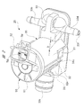
- FIG. 2 is a perspective view of the washer pump of FIG. 1 viewed from the motor cover side
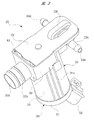
- FIG. 3 is a perspective view of the washer pump of FIG. 1 viewed from the cover member side
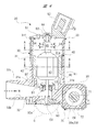
- FIG. 4 is a washer pump along the axial direction of the armature shaft. The cross-sectional views are respectively shown.
- the washer pump 20 includes a housing 30 having a substantially T-shaped cross section formed by injection molding of a resin material such as plastic.
- the housing 30 is a large part among the parts constituting the washer pump 20, and forms an outline of the washer pump 20. In other words, the washer pump 20 having a small physique can be realized by downsizing the housing 30.
- the housing 30 includes a motor housing portion 31, a pump housing portion 32, and a valve body housing portion 33.
- FIG. 5 (a) and 5 (b) are perspective views for explaining a magnet fixing structure to the motor housing portion
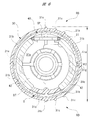
- FIG. 6 is a cross-sectional view of the motor housing portion along a direction intersecting the axial direction of the armature shaft. .
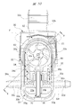
- the motor housing portion 31 is formed in a substantially cylindrical shape, and a motor chamber 31a for housing the motor 40 is formed on the radially inner side thereof.
- a plurality of support ribs 31 b that support the radially outer side of the yoke 41 that forms the motor 40 are provided on the radially inner side of the motor housing portion 31.
- These support ribs 31 b also serve to reinforce the motor housing portion 31.
- Each support rib 31 b extends in the axial direction of the motor housing portion 31 and is disposed at a predetermined interval in the circumferential direction of the motor housing portion 31. Thereby, rattling in the motor accommodating part 31 of the motor 40 is suppressed, without making the mounting operation
- a pair of rib groups RB each including three reinforcing ribs 31c are provided on the outer side in the radial direction of the motor accommodating portion 31, that is, on the outer peripheral portion. These rib groups RB are provided so as to correspond to the downsizing (thinning) of the motor housing portion 31 and play a role of reinforcing the motor housing portion 31.
- a total of six reinforcing ribs 31 c extend in the axial direction of the motor housing portion 31, similarly to the support ribs 31 b provided on the radially inner side of the motor housing portion 31.
- the pair of rib groups RB are arranged at an interval of about 180 degrees so as to face each other about the axis of the motor housing portion 31.
- the distance between the tops of the reinforcing ribs 31c farthest from each other is set to W2.
- the motor housing portion 31 forming the housing 30 is a portion held by each tank side holding portion 14 (see FIG. 1) of the washer tank 10.
- a pair of reinforcing ribs 31c having a mutual separation dimension of W2 are sandwiched between the tank side holding portions 14. That is, the separation dimension W2 at the top of the reinforcing ribs 31c farthest from each other is set to be slightly larger than the separation dimension W1 between the tank holding parts 14 (W2> W1).
- W2> W1 the separation dimension W1 between the tank holding parts 14
- a magnet support portion 31 d is provided on the radially inner side of the motor housing portion 31.
- the magnet support portion 31 d is provided so as to protrude from the bottom portion BT of the motor housing portion 31, and is disposed on the radially inner side of the motor housing portion 31 with a predetermined gap S.
- the magnet support portion 31d is formed in a substantially arc shape in cross section, and at one side in the width direction (lower side in FIG. 6) of the pair of magnets 42 forming the motor 40 on both sides in the width direction (left and right sides in FIG. 6). I support it.
- a pair of magnet mounting portions 31 e are provided on the radially inner side of the motor housing portion 31. These magnet mounting portions 31e are arranged at an interval of 180 degrees so as to face each other around the axis of the motor housing portion 31.
- Each magnet placement portion 31e is formed in a shape substantially the same as the magnet support portion 31d, and is provided so as to protrude from the bottom portion BT of the motor housing portion 31 in the same manner as the magnet support portion 31d.
- Each magnet placement portion 31e supports one end side in the height direction of the pair of magnets 42 (the lower side in FIG. 4).
- a first opening 31 f is formed on the side opposite to the bottom side along the axial direction of the motor housing portion 31 (upper side in FIG. 4), and the first opening 31 f is formed by the motor cover 50. It is blocked. That is, the motor chamber 31 a is closed with the motor cover 50.
- the motor cover 50 and the motor accommodating part 31 are mutually adhere
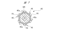
- FIG. 7 is a cross-sectional view of the commutator along the line AA in FIG. 4
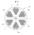
- FIG. 8 is a cross-sectional view of the armature core along the line BB in FIG. 4
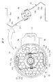
- FIG. 9 is a brush structure attached to the inside of the motor cover. Explanatory drawing explaining each is shown.
- a motor 40 is accommodated in the motor accommodating portion 31.
- the motor 40 includes a motor cover 50 that closes the first opening 31 f of the motor housing 31.
- the motor 40 includes a yoke 41 whose section is formed in a substantially cylindrical shape by pressing a steel plate or the like, and a portion along the circumferential direction is cut away. 5 and 6, the outer side in the radial direction of the yoke 41 is supported by a plurality of support ribs 31b, and the yoke 41 enters the predetermined gap S. That is, the magnet support portion 31 d is disposed on the radially inner side of the yoke 41.
- the yoke 41 is formed with a notch 41 a extending in the axial direction, and the notch 41 a has a positioning protrusion formed on the radially inner side of the motor accommodating portion 31. 31g has entered. Accordingly, the yoke 41 is fixed in a state where the yoke 41 is positioned in the circumferential direction of the motor housing portion 31. Although the positioning and fixing of the yoke 41 in the axial direction of the motor housing portion 31 is not shown in detail, the yoke 41 is partly attached to one side of the bottom portion BT of the motor housing portion 31 (the lower side in FIG. 4). ) Is performed by partial contact. In this way, the yoke 41 (motor 40) is fixed inside the motor chamber 31a.
- Two (two-pole) magnets (permanent magnets) 42 are fixed inside the yoke 41 in the radial direction. Specifically, the radially inner side of one magnet 42 is magnetized to the S pole, and the radially inner side of the other magnet 42 is magnetized to the N pole.
- Each magnet 42 is formed in a substantially arc shape in cross section, and its radial outer side is fixed in contact with the radial inner side of the yoke 41. That is, the yoke 41 forms a magnetic path through which the magnetic lines of force of each magnet 42 pass.
- each magnet 42 is in contact with each magnet placement portion 31e, and one end in the width direction of each magnet 42 is in contact with both sides in the width direction of the magnet support portion 31d.
- the other end in the height direction of each magnet 42 (upper side in FIG. 4) is a plurality of support claws formed on the other axial side of the yoke 41 (upper side in FIG. 4).
- the other end in the width direction (upper side in FIG. 6) of each magnet 42 is elastically supported by a spring pin SP formed in a substantially U shape. That is, each magnet 42 is pressed against the yoke 41 by the spring force of the spring pin SP without being rattled.
- each magnet 42 is fixed to the yoke 41 with one spring pin SP and the magnet support portion 31d without using two spring pins SP. That is, since the magnet support portion 31d is made of a nonmagnetic material, it is not necessary to adversely affect the magnetic path formed by each magnet 42. Therefore, each magnet 42 can be further reduced in size, and thus the washer pump 20 can be further reduced in size and weight.
- an armature core 43 is rotatably provided on the inner side in the radial direction of each magnet 42 through a predetermined gap (air gap).
- An armature shaft (rotating shaft) 44 passes through and is fixed to the rotation center of the armature core 43, that is, the rotation center of the motor 40. That is, the armature shaft 44 rotates together with the armature core 43.
- One end side in the axial direction of the armature shaft 44 is rotatably supported by a first bearing B1 mounted on the bottom portion BT of the motor housing portion 31, and the other end side in the axial direction of the armature shaft 44 is mounted on the motor cover 50.
- the second bearing B2 is rotatably supported.
- a commutator (commutator) 45 to which the two power supply brushes 54 are slidably contacted is fixed near the armature core 43 on the other axial end side of the armature shaft 44.
- the commutator 45 includes a total of six segments (commutator pieces) 45 a, and these segments 45 a are equally spaced in the circumferential direction (60 degrees) around the axis of the armature shaft 44. Are arranged at intervals).
- Each segment 45a is hardened by mold resin MR so that it may have a substantially cylindrical shape.
- the coils 46 are hooked on the hook portions FK of the segments 45a.
- the armature core 43 is formed in a substantially cylindrical shape by laminating a plurality of steel plates, and has a total of six slots 43a corresponding to the six segments 45a as shown in FIG. In other words, the armature core 43 includes a total of six teeth T.
- a coil 46 is wound around each slot 43a by overlapping winding.
- the lap winding is a winding method in which the coil 46 is wound like a frame around the slots 43a facing each other around the armature shaft 44. That is, in the present embodiment, by providing a total of six slots 43a, the mounting of the coil 46 to the armature core 43 can be completed in three winding operations by the double flyer method. Therefore, the time required for the winding work can be shortened and the cost can be reduced.
- the coil 46 is made of a copper wire (such as an enamel wire) whose outer periphery is subjected to insulation treatment.
- the armature core 43 rotates in the forward and reverse directions at a predetermined rotational speed in accordance with the magnitude and direction of the drive current supplied to each power supply brush 54.
- One end side of a pair of power supply terminals TM (see FIG. 9) is electrically connected to each power supply brush 54, and the other end side of each power supply terminal TM is a connector connection portion 52 provided on the motor cover 50. Is projected inside.
- the motor cover 50 is formed in a predetermined shape by a resin material such as plastic, and is formed in a substantially disk shape that closes the first opening 31 f of the motor housing portion 31.
- a cover body 51 is provided.
- a connector connecting portion 52 formed in a substantially box shape to which a vehicle-side power supply connector (not shown) is mounted is provided on the outside of the cover main body 51.
- a second bearing B2 that rotatably supports the other axial end of the armature shaft 44 is provided inside the cover main body 51 and in the center thereof.
- a pair of holding plate fixing portions 51a are provided inside the cover main body 51 so as to face each other with an interval of 180 degrees around the second bearing B2.
- These holding plate fixing portions 51a are arranged on the radially outer side of the cover body 51, and the base end portion 53a of the holding plate 53 is fixed to each holding plate fixing portion 51a without rattling. That is, the base end portion 53 a of the holding plate 53 is attached to the inside of the cover main body 51.
- each power supply terminal TM supplies drive current from a power supply connector on the vehicle side to each power supply brush 54 via a pair of holding plates 53. That is, one end side of each power supply terminal TM is electrically connected to each power supply brush 54 via each holding plate 53.
- each holding plate 53 and each power supply brush 54 are shaded for clarity of illustration.
- the pair of holding plates 53 are formed in the same shape, and are formed by bending a long elastic member made of brass or the like into a substantially V shape. That is, each holding plate 53 has a spring property.
- a base end portion 53 a fixed to the holding plate fixing portion 51 a is provided on one side in the longitudinal direction of the holding plate 53, and a power supply brush 54 formed in a substantially rectangular parallelepiped shape is provided on the other side in the longitudinal direction of the holding plate 53.
- a brush holding portion (tip portion) 53b for holding is provided.
- the two bending parts 53c are provided in the part near the base end part 53a of the brush holding
- each power supply brush 54 can be saved in a space-saving manner with the commutator 45 interposed therebetween as shown by the imaginary line in FIG. It can easily be placed facing each other. Further, by providing the two bent portions 53c near the base end portion 53a of the holding plate 53, each power supply brush 54 is brought into sliding contact with the commutator 45 with an optimal pressing force. Furthermore, by providing two bent portions 53c near the base end portion 53a of the holding plate 53 and setting the bent angle of the bent portion 53c to an optimum value (approximately 90 degrees), the right side of FIG. As shown in FIG.
- the power supply brushes 54 are arranged in the extending direction of the brush holding portion 53b before the commutator 45 is assembled. Thereby, each power supply brush 54 can be used up to the end. In other words, it is possible to reduce the size of each power supply brush 54, which is advantageous for reducing the size and weight of the washer pump 20 from this viewpoint.
- the motor 40 of the present embodiment employs a 2-pole 6-slot 2-brush electric motor.
- each power supply brush 54 against the commutator 45 can be adjusted more finely.
- a honeycomb-shaped rib (a shape in which regular hexagons are arranged without gaps) is formed inside the cover main body 51.
- the rib 55 protrudes from the cover body 51 toward the motor 40 at a predetermined height (about 1.0 mm) and is provided integrally with the cover body 51.
- the rib 55 is provided to reinforce the cover body 51 in order to cope with the thinning of the cover body 51. Further, when the vehicle-side power supply connector is inserted into and removed from the connector connecting portion 52, a relatively large load acts on the cover body 51. However, the cover body 51 has sufficient strength by providing the rib 55. .
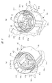
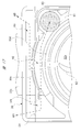
- FIG. 10 is a plan view showing the pump chamber side (cover member omitted) of the washer pump
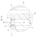
- FIG. 11 is an enlarged view of a broken line circle C portion of FIG. 4
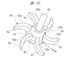
- FIG. 12 is a perspective view illustrating the detailed structure of the impeller. ing.
- an impeller 60 is fixed to one end of the armature shaft 44 in the axial direction so as to be integrally rotatable.
- the impeller 60 and the armature shaft 44 are fixed by so-called D-cut fitting so that they cannot be rotated relative to each other. That is, the impeller 60 is rotated by the motor 40.
- the impeller 60 includes an impeller body 61 fixed to the armature shaft 44, and a total of six blades 62 extending radially from the impeller body 61 and curved in a substantially crescent shape.
- hook-shaped protrusions formed in an arc shape with a predetermined radius of curvature R are formed on the armature core 43 side (the hook-shaped recess 32 d side) of the six blades 62 along the axial direction of the armature shaft 44. 62a is formed.
- These bowl-shaped convex parts 62a are provided along the bowl-shaped concave part 32d forming the pump chamber 32a.
- the radius of curvature of the bowl-shaped recess 32d that forms the pump housing portion 32 is also R, whereby the impeller 60 faces the bowl-shaped recess 32d with a predetermined gap therebetween.
- annular flange portion 63 bulging outward in the radial direction of the impeller body 61 is formed.
- the flange portion 63 is disposed downstream of the impeller body 61 along the flow direction of the cleaning liquid W (broken arrow in FIG. 12). As a result, as indicated by the broken-line arrows in FIG. 12, the flowing direction of the cleaning liquid W is quickly directed toward the tip side of each blade 62 to improve the pump capacity.
- the pump housing portion 32 includes a pump chamber 32a and a cleaning liquid inflow hole 32b provided on the upstream side (washer tank 10 side) of the pump chamber 32a.
- the cleaning liquid inflow hole 32b is formed inside the suction pipe 32c inserted into the insertion hole 15 of the washer tank 10 (see FIG. 1).
- the flow path area of the cleaning liquid inflow hole 32b gradually decreases from the washer tank 10 side toward the pump chamber 32a side. As a result, the flow rate of the cleaning liquid W sucked into the cleaning liquid inflow hole 32b is increased so that it can be efficiently sucked into the pump chamber 32a.
- the pump chamber 32a is formed in a flat shape in which the impeller 60 can be rotatably accommodated through a predetermined gap, and has a bowl-shaped recess 32d in which the radius of curvature is set to R.
- the opening part of the pump chamber 32a and each valve chamber 33a, 33b forms the 2nd opening part 30a of the housing 30, and the said 2nd opening part 30a is obstruct
- the second opening 30a is also formed on the side of the breathing hole 80 described later of the housing 30.
- the part with the breathing hole 80 of the 2nd opening part 30a is also obstruct
- the cover member CV is formed in a substantially flat plate shape from a resin material such as plastic and is firmly fixed to the housing 30 by ultrasonic welding or the like.
- an armature shaft 44 is disposed across the downstream side (pump chamber 32a side) of the cleaning liquid inflow hole 32b. Therefore, a lip seal LS made of rubber or the like is provided between the cleaning liquid inflow hole 32 b and the armature shaft 44. Thereby, the cleaning liquid W flowing through the cleaning liquid inflow hole 32b is prevented from leaking into the motor chamber 31a.
- the impeller 60 is also rotated in the forward / reverse direction inside the pump chamber 32a. At this time, regardless of the rotation direction of the impeller 60, the cleaning liquid W flowing through the cleaning liquid inflow hole 32b is sucked into the pump chamber 32a.
- FIGS. 13A and 13B are sectional views for explaining the position of the discharge hole with respect to the opening of the valve chamber
- FIGS. 14A and 14B are perspective views showing the valve unit
- FIG. Sectional views taken along line DD in (a) are respectively shown.
- the valve body accommodating portion 33 includes a front side valve chamber (valve chamber) 33 a and a rear side disposed on the opposite side of the pump chamber 32 a from the cleaning liquid inflow hole 32 b side.
- a valve chamber (valve chamber) 33b is provided. That is, the cleaning liquid W discharged from the pump chamber 32a flows into the pair of valve chambers 33a and 33b.
- the valve body accommodating portion 33 is integrally provided with a front side discharge pipe 33c corresponding to the front side valve chamber 33a, and a rear side discharge pipe 33d is integrally provided corresponding to the rear side valve chamber 33b. ing.
- the cleaning liquid W that has flowed into the front side valve chamber 33a flows out through the valve unit 70 into the front side discharge hole 33e inside the front side discharge pipe 33c.
- the cleaning liquid W that has flowed into the rear side valve chamber 33b flows through the valve unit 70 into the rear side discharge hole 33f inside the rear side discharge pipe 33d.
- the front side discharge hole 33e and the rear side discharge hole 33f constitute a pair of discharge holes in the present invention.
- a front-side flow path 34 is provided between the pump chamber 32a and the front-side valve chamber 33a. Further, a rear-side flow path 35 is provided between the pump chamber 32a and the rear-side valve chamber 33b.
- the motor housing portion 31, the pump chamber 32a, the pair of valve chambers 33a and 33b, the pair of discharge holes 33e and 33f, and the pair of flow paths 34 and 35 are integrally provided in one housing 30, respectively. .
- the cleaning liquid W flows into the valve chambers 33a and 33b depending on the rotation direction of the impeller 60.
- the cleaning liquid W flows from the pump chamber 32a toward the front side flow path 34 by rotating the impeller 60 counterclockwise.
- the cleaning liquid W flows from the pump chamber 32a toward the rear-side flow path 35 by rotating the impeller 60 in the clockwise direction.
- the motor 40 by forming each blade 62 of the impeller 60 in a substantially crescent shape, the motor 40 (see FIG. 4) flows out to the front-side flow path 34 when the rotational speed of the motor 40 (see FIG. 4) is the same rotational speed.
- the flow rate of the cleaning liquid W is larger than that of the cleaning liquid W flowing out to the rear side flow path 35. This is because it is necessary to increase the spray pressure of the cleaning liquid W because the front side receives traveling wind as compared with the rear side. That is, in the washer pump 20 of the present embodiment, the spray position of the cleaning liquid W with respect to the windshield (cleaning surface) on the front side can be made substantially constant regardless of the traveling wind.
- the front side valve chamber 33a side and the rear side valve chamber 33b side are respectively the front side discharge holes 33e. And it extends to the position of the rear side discharge hole 33f.
- the cross-hatched areas in FIG. 10 are the front-side channel 34 and the rear-side channel 35.
- the front side valve chamber 33a and the rear side valve chamber 33b are respectively provided with curved wall portions 33g. These curved wall portions 33g are formed in front of the outlet portions of the front-side channel 34 and the rear-side channel 35, and the cleaning liquid W discharged from the front-side channel 34 and the rear-side channel 35 is respectively curved walls. Rectification is performed along the portion 33g. Thus, the rapid diffusion of the cleaning liquid W into the valve chambers 33a and 33b is suppressed, and the cleaning liquid W is rectified in the valve chambers 33a and 33b, so that the cleaning liquid W is within the valve chambers 33a and 33b. Turbulence is suppressed.
- the shape of the front channel 34 and the shape of the rear channel 35 are different from each other.
- the cross-sectional shape in the direction intersecting the longitudinal direction of each flow path 34, 35 is formed in a substantially rectangular shape, and the depth dimensions of each flow path 34, 35 are the same.
- the front side flow path 34 constitutes one flow path in the present invention
- the rear side flow path 35 constitutes the other flow path in the present invention.
- the flow passage area on the pump chamber 32a side along the longitudinal direction of the front flow passage 34 is set to be smaller than the flow passage area on the front valve chamber 33a side along the longitudinal direction of the front flow passage 34.
- the outer wall portion 34 a disposed on the outer side (left side in the drawing) of the front-side channel 34 is provided near the side wall 30 b of the housing 30 and in parallel with the side wall 30 b.
- the inner side wall portion 34b disposed inside the front side flow path 34 (right side in the drawing) is provided on the inner side of the housing 30 than the side wall 30b of the housing 30, and is inclined with respect to the side wall 30b.
- the inner wall portion 34b gradually increases the flow passage area from the pump chamber 32a side of the front side flow passage 34 toward the front side valve chamber 33a side. That is, the inner wall part 34b constitutes an inclined wall in the present invention.
- the outer side wall part 34a is facing the inner side wall part 34b, and comprises the opposing wall in this invention.
- the pump chamber 32a side along the longitudinal direction of the front side flow path 34 is narrowed, and the flow rate of the cleaning liquid W flowing out from the pump chamber 32a to the front side flow path 34 is increased. Therefore, the flow of the cleaning liquid W into the front side valve chamber 33a is made smooth, and the subsequent rapid diffusion of the cleaning liquid W into the front side valve chamber 33a is suppressed.
- the front side flow path 34 is provided corresponding to the injection of the cleaning liquid W to the windshield on the front side of the vehicle. That is, the washer pump 20 according to the present embodiment employs a structure suitable for application to the front side where the injection pressure of the cleaning liquid W needs to be increased.
- the spray pressure of the cleaning liquid W on the rear side does not need to be increased as much as the spray pressure of the cleaning liquid W on the front side. Therefore, giving priority to the ease of manufacture of the housing 30, the flow area on the pump chamber 32 a side along the longitudinal direction of the rear side flow path 35 and the rear side valve chamber along the longitudinal direction of the rear side flow path 35.
- the channel area on the 33b side is the same channel area.
- the outer wall portion 35a is disposed outside the rear side flow path 35 (right side in the figure), and is disposed inside the rear side flow path 35 (left side in the figure).
- the inner wall portions 35 b are parallel to each other, and both are parallel to the side wall 30 b of the housing 30.
- the flow passage area of the front side flow passage 34 on the pump chamber 32a side is set smaller than the flow passage area of the rear side flow passage 35 on the pump chamber 32a side.
- the flow area on the front valve chamber 33a side of the front flow path 34 is set larger than the flow area on the rear valve chamber 33b side of the rear flow path 35.
- the length of the inner wall portion 34b from the front side valve chamber 33a to the pump chamber 32a is longer than the length of the inner wall portion 35b from the rear side valve chamber 33b to the pump chamber 32a.
- the pump capacity is changed according to the rotation of the motor 40 in the forward direction or the reverse direction, and the shapes of the front side flow path 34 and the rear side flow path 35 are changed.
- the passage 34 has a larger flow rate and higher flow rate of the cleaning liquid W than the rear side passage 35.
- a chamber 36 is provided.
- a diaphragm type valve unit 70 is mounted in the valve storage chamber 36. That is, the valve unit 70 partitions the pair of valve chambers 33a and 33b.
- the valve main body 71b (refer FIG. 15) of the switching valve 71 which comprises the valve unit 70 is arrange
- a front-side discharge hole 33e and a rear-side discharge hole 33f are disposed on both sides of the switching valve 71 in the moving direction of the valve body 71b.
- the valve body 71b of the switching valve 71 has a high internal pressure in the front-side valve chamber 33a. Then, the front discharge pipe 33c is opened and the rear discharge pipe 33d is closed. As a result, the cleaning liquid W flows only through the front discharge holes 33e and is then sprayed toward the windshield on the front side.
- the valve main body 71b of the switching valve 71 opens the rear side discharge pipe 33d and closes the front side discharge pipe 33c when the internal pressure of the rear side valve chamber 33b increases. As a result, the cleaning liquid W flows only through the rear-side discharge hole 33f and is then sprayed toward the rear-side windshield.
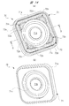
- valve unit 70 is mounted in the valve storage chamber 36 in a predetermined direction. That is, the valve unit 70 has an assembling direction with respect to the valve housing chamber 36.
- a front side discharge hole 33e is opened in the front side valve chamber 33a, and one side surface 70a (FIG. 15) of the valve unit 70 is formed around the front side discharge hole 33e. 1st opposing surface 36a with which a reference) is opposed is provided.
- a pair of rectifying the cleaning liquid W flowing in the front side valve chamber 33a toward the front side discharge hole 33e that is, the center of the valve main body 71b.
- the curved portion 36b is provided.
- a rear side discharge hole 33f is opened in the rear side valve chamber 33b, and the other side surface 70b (FIG. 15) of the valve unit 70 is formed around the rear side discharge hole 33f.
- a second facing surface 36c is provided to face the other.
- a pair of rectifying the cleaning liquid W flowing in the rear side valve chamber 33b toward the rear side discharge hole 33f that is, the center of the valve body 71b.
- the curved portion 36d is provided.
- the second opposing surface 36c is provided with a pair of recesses (concave portions) 36e into which the misassembly prevention protrusions 72c (see FIG. 15) provided on the other side surface 70b of the valve unit 70 enter and are engaged. ing.
- These hollow portions 36e are recessed toward the rear side discharge pipe 33d (see FIG. 10). In other words, each recess 36e is provided to be recessed on one side in the moving direction of the valve body 71b.
- the hollow part 36e is not provided in the front side valve chamber 33a side (refer Fig.13 (a)). That is, in the state where one side surface 70a of the valve unit 70 is opposed to the second opposing surface 36c and the other side surface 70b of the valve unit 70 is opposed to the first opposing surface 36a, there is no place for the misassembly prevention protrusion 72c. . Therefore, the valve unit 70 protrudes from the valve accommodating chamber 36 and is in a state where it is not correctly assembled, that is, an “incorrectly assembled state”.
- the erroneous assembly prevention mechanism including the recessed portion 36 e and each misassembly prevention protrusion 72 c causes the valve unit 70 to protrude from the valve storage chamber 36.
- the assembly operator or the like easily grasp (notify) the “erroneous assembly state” in appearance.
- the distance between the center portion of the front side discharge hole 33e and the rear side discharge hole 33f and the lower end portion 30c on the second opening 30a side of the housing 30 is set to H. Yes.
- This distance H is larger than the diameter D (see FIG. 2) of the thickest portions of the front discharge pipe 33c and the rear discharge pipe 33d (H> D).
- the discharge pipes 33c and 33d are arranged on the motor accommodating portion 31 side (upper side in the drawing) with respect to the lower end portion 30c of the housing 30, respectively. Specifically, as shown in FIG.
- the pair of discharge holes 33e and 33f are closer to the motor chamber 31a than the lower end in the axial direction of the motor 40 of the suction pipe 32c and from the upper end in the axial direction of the motor 40 of the suction pipe 32c. It is provided near the cover member CV. Thereby, the axial height of the motor 40 in the washer pump 20 can be reduced. Therefore, it is possible to reduce the size and weight of the washer pump 20 while suppressing the shape of the washer pump 20 from becoming complicated.
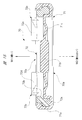
- the valve unit 70 is formed in a substantially square plate shape.
- the valve unit 70 includes a switching valve (valve element) 71 formed of a thin rubber material or the like, and a frame body 72 that is attached to the switching valve 71 and reinforces the switching valve 71.
- the frame body 72 is shaded to clearly distinguish the switching valve 71 and the frame body 72.
- the switching valve 71 includes a mounting portion 71a formed in a substantially square shape (rectangular shape) when viewed from the moving direction of the valve body 71b.
- the mounting portion 71a is mounted in the valve storage chamber 36 (see FIG. 10).
- the mounting portion 71a of the switching valve 71 is also mounted inside the cover member-side housing portion CM (see FIG. 3) provided in the cover member CV.
- the mounting portion 71 a has a substantially U-shaped cross section, and a part of the main body 72 a of the frame 72 is mounted inside the mounting portion 71 a. That is, the main body portion 72a supports the mounting portion 71a, whereby the mounting portion 71a is reinforced by the main body portion 72a, and the mounting portion 71a is deformed when the mounting portion 71a is mounted to the valve storage chamber 36 or the like. It is prevented from tilting or tilting.
- a valve body 71b formed in a substantially disc shape is provided on the radially inner side of the mounting portion 71a.
- the valve body 71b is moved in the extending direction of the discharge pipes 33c and 33d according to the internal pressure of the valve chambers 33a and 33b. Thereby, the front side discharge pipe 33c and the rear side discharge pipe 33d are opened and closed by the both sides in the thickness direction of the valve body 71b.
- an annular thin portion 71c that is deformed when the valve main body 71b is moved is provided between the valve main body 71b and the mounting portion 71a. And as shown in FIG. 15, the thin part 71c is made thinner than the valve main body 71b, and the cross section is a bending shape. Accordingly, the discharge pipes 33c and 33d can be reliably opened and closed while facilitating the movement of the valve main body 71b.
- the frame body 72 is formed of a plastic having a higher rigidity than that of the switching valve 71, and thus the mounting portion 71a of the switching valve 71 can be sufficiently reinforced.
- the frame body 72 includes a main body portion 72a formed in a substantially square shape (square shape) when viewed from the moving direction of the valve main body 71b, and a part of the main body portion 72a is mounted inside the mounting portion 71a.
- a circular hole 72b that is set to have an inner diameter that is substantially the same as the outer diameter of the thin portion 71c of the switching valve 71 is provided on the radially inner side of the main body 72a. Thereby, the valve main body 71b can move inside the radial direction of the circular hole 72b without being obstructed by the frame body 72.
- the misassembly prevention protrusion (convex part) 72c is provided in each of the four corners of the main body 72a. These misassembly prevention protrusions 72c protrude from the other side surface 70b of the valve unit 70, as shown in FIG. That is, each misassembly prevention protrusion 72c is provided to protrude to one side in the movement direction of the valve body 71b.
- the outer side of the misassembly preventing projection 72c along the radial direction of the frame body 72 is engaged with the inner side of the recess 36e along the radial direction of the frame body 72. In the case of the relationship, the valve unit 70 does not protrude from the valve storage chamber 36 and is in a correctly assembled state.
- each misassembly prevention protrusion 72c provided at the four corners of the main body 72a are disposed on the radially outer side of the circular hole 72b, and do not hinder the movement of the valve main body 71b.
- each misassembly prevention protrusion 72c is provided in the dead space of the main body 72a.
- the frame body 72 cannot be assembled to the switching valve 71 such that each misassembly prevention protrusion 72c faces the thin portion 71c.
- each misassembly prevention protrusion 72c has a function of preventing misassembly of the valve unit 70 itself.
- the misassembly prevention protrusion 72c is formed in a substantially triangular shape in plan view, and includes a circular hole 72b, that is, an inclined surface 72d that gradually falls toward the center of the valve body 71b.
- each misassembly prevention protrusion 72c is exposed at four corners (not shown) in the rear side valve chamber 33b under the state where the valve unit 70 is mounted in the valve storage chamber 36. Therefore, by providing the inclined surface 72d on each misassembly prevention protrusion 72c, the rectifying effect of the cleaning liquid W flowing in the rear valve chamber 33b is not lowered.
- each inclined surface 72d serves to direct the direction of the cleaning liquid W flowing in the rear valve chamber 33b toward the valve body 71b.
- the inclined surface 72d formed on the recess 36e side along the moving direction of the valve body 71b guides the flow of the cleaning liquid W toward the center of the valve body 71b.
- the hardness of the movement differs depending on the movement direction of the valve main body 71b. That is, the valve main body 71b is hard to move in the direction of the solid line arrow M1 (upward in the figure) and soft to move in the direction of the broken line arrow M2 (downward in the figure). More specifically, the movement or deformation of the thin portion 71c is obstructed by the main body portion 72a when moving in the direction of the solid line arrow M1, but when moving in the direction of the broken line arrow M2, the thin portion 71c is moved. The movement or deformation is not hindered by the main body 72a. Thereby, the hardness of the movement differs depending on the moving direction of the valve main body 71b.
- the movement of the valve body 71b in the hard direction is the front side, and the movement of the valve body 71b in the soft direction is the rear side.
- the cleaning liquid W can be sprayed onto the rear side windshield with a weak injection pressure, and the wide area of the rear side windshield can be evenly wetted with the cleaning liquid W.
- the injection pressure of the cleaning liquid W is optimized between the front side and the rear side by providing a difference in the injection pressure of the cleaning liquid W between the front side and the rear side.
- the valve unit 70 has an assembling directionality. Therefore, by providing four misassembly prevention protrusions 72c on the valve unit 70 side and a pair of recesses 36e on the rear side valve chamber 33b side, the washer pump 20 is prevented from being assembled incorrectly. . That is, by providing a misassembly prevention mechanism including the recess 36e and the misassembly prevention protrusion 72c between the housing 30 and the frame body 72, the yield in the assembly process of the washer pump 20 is improved.
- FIG. 16 is a sectional view of the housing along the line EE in FIG. 10
- FIG. 17 is a partially enlarged view of the broken line circle F portion of FIG. 10, and FIG. Respectively.
- the motor housing portion 31 formed in a substantially cylindrical shape is held by a pair of tank side holding portions 14 provided in the washer tank 10, whereby the washer pump 20 is attached to the washer tank 10. Wearing. Accordingly, a substantially triangular dead space DS is formed between the washer tank 10 having a flat surface and the motor housing portion 31 having an arc surface as shown by a broken-line circle in FIG. A corner portion 32e is provided at a portion of the pump housing portion 32 corresponding to the dead space DS. That is, the corner portion 32 e is disposed in the housing 30 between the motor housing portion 31 and the washer tank 10 in a state where the washer pump 20 is mounted on the washer tank 10.
- a breathing hole 80 that communicates the inside and outside of the motor housing 31 is provided between the motor housing 31 and the corner 32 e. More specifically, one end side (lower side in FIG. 16) of the breathing hole 80 is opened inside the motor housing portion 31, and the other end side (upper side in FIG. 16) of the breathing hole 80 is a corner portion. Opened in the interior of 32e. Thus, the breathing hole 80 communicates between the motor chamber 31 a in the motor housing 31 and the outside of the housing 30. The breathing hole 80 is disposed in the corner portion 32e in the dead space DS (see FIG. 2) of the pump housing portion 32, but does not communicate with the pump chamber 32a.
- the breathing hole 80 penetrates in the axial direction of the motor accommodating portion 31 and is formed in a step shape as shown in the partial enlarged view in the broken line circle of FIG. As a result, air is formed between the corner portion 32e (outside of the housing 30) outside the motor housing portion 31 and in the dead space DS of the pump housing portion 32, and the motor chamber 31a in the motor housing portion 31. (AIR) can come and go.
- the breathing hole 80 is disposed in the corner portion 32e of the housing 30 that can be the dead space DS as described above.
- the housing 30 does not become unnecessarily large and a sufficient breathing function can be provided.
- the breathing hole 80 can be disposed within the outer region including the washer pump 20 and the washer tank 10 with the washer pump 20 mounted on the washer tank 10.
- a porous filter 81 that restricts the passage of water while allowing the passage of air.
- the porous filter 81 is provided so as to close the breathing hole 80 and is fixed to the inside of the corner portion 32e (housing 30) by ultrasonic welding or the like on the outer peripheral portion thereof.
- the inner side of the corner 32e of the porous filter 81 is not limited to ultrasonic welding, and a double-sided tape, an adhesive, or the like may be used.
- each discharge pipe 33 c is provided on the radially outer side of the pump chamber 32 a in the housing 30 and on the upstream side of the porous filter 81 provided in the breathing hole 80 (outside of the housing 30).
- 33d is provided with a first air passage 82 over substantially the entire width direction of the housing 30 along the extending direction. That is, the first air passage 82 is provided so as to extend in the width direction of the housing 30 intersecting the suction direction of the cleaning liquid W (up and down direction in FIG. 17), and one end side (right side in the figure) of the first air passage 82 is provided. The other end side of the breathing hole 80 is communicated.
- the first ventilation path 82 includes an arc wall 30d of the housing 30 that forms the pump chamber 32a, an outer wall 30e of the housing 30 that is provided radially outside the arc wall 30d, and a cover member CV (see FIG. 3). It is formed between. That is, a part of the inside of the corner portion 32e, the porous filter 81 provided inside the corner portion 32e so as to close the breathing hole 80, and the first air passage 82 are respectively in the housing 30. 2 Covered by a cover member CV that closes the opening 30a. Accordingly, the breathing hole 80, the porous filter 81, and the first air passage 82 cannot be viewed from the axial direction of the armature shaft 44, and are hidden by the cover member CV (see FIG. 3).
- a cutout portion 30f formed by cutting out a part of the outer wall 30e is disposed on the other side in the width direction of the housing 30 that intersects the suction direction of the cleaning liquid W (left side in FIG. 17).
- air (AIR) flows back and forth between the outside of the housing 30 and the breathing hole 80 via the first air passage 82 as indicated by the broken-line arrows in the drawing. That is, the breathing hole 80 (porous filter 81) is disposed in a deep part covered with the cover member CV along the width direction of the housing 30.
- the outside of the housing 30 and the porous filter 81 are separated from each other. This makes it difficult for rainwater, dust, etc. to reach the porous filter 81. Therefore, a sufficient respiratory function can be maintained over a long period of time, and the life of the washer pump 20 can be extended.
- the second ventilation path 83 is provided further upstream of the first ventilation path 82.
- the second ventilation path 83 is connected to the first ventilation path 82 at the corner 32e on the opposite side of the breathing hole 80 from the suction pipe 32c. ing.
- the second ventilation path 83 is formed so as to be folded back to the first ventilation path 82, and one end side thereof communicates with the other end side of the first ventilation path 82 via a notch 30 f. Similar to the first ventilation path 82, the second ventilation path 83 is provided over substantially the entire width direction of the housing 30 that intersects the suction direction of the cleaning liquid W.
- the second ventilation path 83 is not blocked by the cover member CV, and as shown in FIGS. 3 and 17, the entire width direction of the housing 30 intersects the suction direction of the cleaning liquid W in the second ventilation path 83. Is open. That is, a part of the inside of the corner portion 32e is covered with the cover member CV. As a result, even if the washer pump 20 is submerged, the second air passage 83 is elongated and has a large opening, making it difficult to form a water film or the like. Inhibition is effectively suppressed.
- a filter member 90 as shown in FIG. 18 may be detachably provided in the breathing hole 80 instead of the porous filter 81 fixed inside the corner portion 32e by ultrasonic welding or the like.
- the filter member 90 can be periodically replaced, and the maintainability of the washer pump 20 can be improved.
- the filter member 90 includes a tube material 91 made of rubber or the like, and a porous filter 92 fixed to one side in the axial direction (upper side in the drawing) of the tube material 91 by ultrasonic welding or the like. .
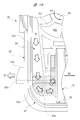
- FIG. 19 is an explanatory diagram for explaining the flow of the cleaning liquid on the front side
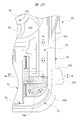
- FIG. 20 is an explanatory diagram for explaining the flow of the cleaning liquid on the rear side.
- the pumping capacity is higher than that when the impeller 60 is rotated in the clockwise direction. Increased as indicated by the solid solid arrows. Further, the flow rate of the cleaning liquid W flowing through the front side flow path 34 is higher than that of the cleaning liquid W flowing through the rear side flow path 35.
- the cleaning liquid W having a high flow rate flowing through the front side flow path 34 is discharged into the front side valve chamber 33a (shaded portion in the figure).
- the flow rate of the cleaning liquid W is high, and the cleaning liquid W is discharged into the front side valve chamber 33a at the front side discharge hole 33e. Therefore, the cleaning liquid W does not become a turbulent flow in the front side valve chamber 33a. Therefore, the cleaning liquid W discharged into the front valve chamber 33a is smoothly collected toward the center of the valve unit 70, that is, the valve body 71b of the switching valve 71.
- the internal pressure of the front side valve chamber 33a is increased, the valve main body 71b is moved in the direction shown by the solid arrow M1 in FIGS. 15 and 19, and the front side discharge hole 33e is opened. Thereafter, the cleaning liquid W is jetted vigorously toward a predetermined launch point of the windshield on the front side. At this time, the rear side discharge hole 33f of the rear side discharge pipe 33d is closed by the valve body 71b.
- the pumping capacity is lower than that when the impeller 60 is rotated in the counterclockwise direction. As shown by the outlined broken arrow, there are few. Further, the flow rate of the cleaning liquid W flowing through the rear side flow path 35 is slower than that of the cleaning liquid W flowing through the front side flow path 34.
- the cleaning liquid W that has flowed through the rear-side flow path 35 is discharged into the rear-side valve chamber 33b (shaded portion in the figure).
- the cleaning liquid W is discharged into the rear side valve chamber 33b at the portion of the rear side discharge hole 33f, and the cleaning liquid W is rectified following the curved wall portion 33g immediately after being discharged into the rear side valve chamber 33b.
- the cleaning liquid W does not become turbulent in the rear side valve chamber 33b. Therefore, the cleaning liquid W discharged into the rear side valve chamber 33 b is smoothly collected toward the center of the valve unit 70, that is, toward the valve body 71 b of the switching valve 71.
- the pump chamber 32a, the valve chambers 33a and 33b, the discharge holes 33e and 33f, and the flow paths 34 and 35 are integrated with the housing 30, respectively. Therefore, when these are formed as separate members, there is no need to form a step or the like that obstructs the flow of the cleaning liquid W in the path through which the cleaning liquid W flows, so that the pressure loss of the cleaning liquid W can be reduced. it can.
- each valve chamber 33a, 33b side of each flow path 34, 35 is extended to the position of each discharge hole 33e, 33f, the washing
- the flow area on the pump chamber 32a side of the front flow path 34 is smaller than the flow area on the front valve chamber 33a side.
- the flow rate of the cleaning liquid W flowing through the passage 34 can be increased, the flow of the cleaning liquid W into the front side valve chamber 33a can be made smooth, and the subsequent rapid diffusion of the cleaning liquid W into the front side valve chamber 33a can be suppressed. Therefore, the turbulent flow of the cleaning liquid W inside each valve chamber 33a, 33b can be suppressed more reliably.
- the front side flow path 34 includes the inner wall portion 34b that gradually increases the flow path area from the pump chamber 32a side to the front side valve chamber 33a side. Therefore, the flow passage area of the front flow passage 34 can be changed linearly from the pump chamber 32a side to the front valve chamber 33a side. Therefore, the turbulent flow in the front side flow path 34 can be suppressed more reliably, and the highly efficient washer pump 20 with less pressure loss can be realized.
- the front-side flow path 34 has the outer wall part 34 a that faces the inner wall part 34 b, and the outer wall part 34 a is closer to the side wall 30 b of the housing 30. Since the inner wall portion 34b is provided in parallel to the side wall 30b and is provided on the inner side of the side wall 30b of the housing 30, the housing 30 is not increased in size, and the inside of the housing 30 is provided from the pump chamber 32a side. A front-side channel 34 whose channel area gradually increases toward the front-side valve chamber 33a can be formed. Therefore, the dedicated design of the cover member CV is not required, and the cost increase can be suppressed.
- the flow area on the pump chamber side of the front side flow path 34 is smaller than the flow area on the pump chamber 32a side of the rear side flow path 35.
- the pump capacity can be varied according to the rotation of the motor 40 in the forward direction or the reverse direction.
- the front-side flow path 34 is provided corresponding to the injection of the cleaning liquid W to the windshield on the front side of the vehicle, the position of the cleaning liquid W to be injected with respect to the front-side windshield affected by the traveling wind is set. It can be made almost constant regardless of the running wind. That is, the cleaning performance of the washer pump 20 can be improved.
- the housing 30 has a motor accommodating portion 31 for accommodating the motor 40, a corner portion 32e disposed between the motor accommodating portion 31 and the washer tank 10, and And a breathing hole 80 communicating between the inside and outside of the motor housing 31 is provided between the motor housing 31 and the corner 32e. Accordingly, the breathing hole 80 can be disposed within the outer region including the washer pump 20 and the washer tank 10 with the washer pump 20 mounted on the washer tank 10. Therefore, it is possible to prevent the respiratory structure from being damaged at the time of installation or the like, and the conventional member for the respiratory structure is not necessary, and it is possible to further reduce the size and weight.
- one end side of the breathing hole 80 is opened inside the motor accommodating portion 31, and the other end side of the breathing hole 80 is opened inside the corner portion 32e.
- the interior of the corner 32e communicates with the outside, and a part thereof is covered with a cover member CV that closes the second opening 30a formed on the breathing hole 80 side of the housing 30.
- the breathing hole 80 is provided with the porous filter 81 that restricts the passage of water while permitting the passage of air. It is possible to reliably prevent rainwater and the like from entering.
- the porous filter 81 is provided inside the corner portion 32e and closes the second opening 30a formed on the breathing hole 80 side of the housing 30. Since it is covered with the cover member CV, it is possible to make rainwater or the like difficult to reach the porous filter 81. Therefore, the porous filter 81 can be kept clean for a long period of time, and the maintenance cycle can be extended.
- one end side of the breathing hole 80 is opened inside the motor housing part 31, and the other end side of the breathing hole 80 is opened inside the corner part 32e.
- the first air passage 82 communicating with the other end side of the breathing hole 80 is provided, and the first air passage 82 is covered with the cover member CV that closes the housing 30. It can be made more difficult to reach rainwater or the like.
- the washer pump 20 since the first ventilation path 82 extends in the width direction of the housing 30 intersecting the suction direction of the cleaning liquid W, the distance of the first ventilation path 82 The rain filter or the like can be made harder to reach the porous filter 81.
- one end side of the first air passage 82 is communicated with the breathing hole 80, and the other end side of the first air passage 82 is provided in the housing 30.
- the second air passage 83 communicates with the air passage 83 and extends in the width direction of the housing 30 and is not covered with the cover member CV.
- a membrane or the like can be made difficult, and rainwater or the like can be made harder to reach the porous filter 81.
- valve unit 70 protrudes from the housing 30 between the housing 30 and the frame body 72, so that the valve unit 70 can be removed from the housing 30.
- An erroneous assembly prevention mechanism is provided which includes a recess 36e for notifying erroneous assembly and an erroneous assembly prevention protrusion 72c.
- valve unit 70 when the valve unit 70 is erroneously assembled to the housing 30, the valve unit 70 protrudes from the housing 30, and the cover member CV that closes the housing 30 cannot be attached to the housing 30. That is, it is possible to prevent the washer pump 20 from being physically assembled and to prevent erroneous assembly of the valve unit 70 to the housing 30. Therefore, the yield of the washer pump 20 can be improved and the reliability of the product can be improved.
- the misassembly prevention mechanism is provided in the housing 30 and has a hollow portion 36e that is depressed on one side in the moving direction of the valve body 71b (switching valve 71), and a frame. It is formed from a misassembly prevention protrusion 72c provided on the body 72 and protruding to one side in the moving direction of the valve main body 71b and engaged with the recess 36e. Therefore, an assembly operator or the like can easily check the dent 36e and the erroneous assembly prevention protrusion 72c by visual observation, and can more reliably prevent erroneous assembly of the valve unit 70 to the housing 30. It becomes.
- the frame body 72 is formed in a square shape when viewed from the moving direction of the valve body 71 b, and the misassembly prevention protrusions 72 c are provided at the four corners of the frame body 72.
- the outer side of the misassembly prevention protrusion 72 c along the radial direction of the frame body 72 is engaged with the inner side of the recessed portion 36 e along the radial direction of the frame body 72. Therefore, the center position of the valve main body 71b and the center positions of the front side discharge pipe 33c and the rear side discharge pipe 33d can be accurately positioned without deviation.
- valve opening characteristics / valve closing characteristics the movement characteristics of the valve main body 71b for each product.
- misassembly prevention protrusions 72 c are provided at the four corners of the frame body 72, any of the four sides formed by the outer periphery of the mounting portion 71 a of the switching valve 71 when the valve unit 70 is assembled to the housing 30. Can be inserted even when facing the housing 30 side, and the insertion direction of the valve unit 70 is not limited.
- the flow of the cleaning liquid W is directed to the center of the switching valve 71 (valve) on the side of the depression 36e along the moving direction of the valve body 71b.
- An inclined surface 72d is formed for guiding toward the main body 71b).
- the rigidity of the frame 72 is higher than the rigidity of the switching valve 71, so that the valve unit 70 is forcibly mistakenly assembled to the housing 30. Can be prevented in advance, and erroneous assembly of the valve unit 70 to the housing 30 can be prevented more reliably.
- the motor chamber 31a, the pump chamber 32a, the valve chambers 33a and 33b, and the discharge holes 33e and 33f are integrally provided in the housing 30, respectively.
- the motor 40 includes the yoke 41 fixed inside the motor chamber 31a, the two magnets 42 fixed inside the yoke 41, and the armature shaft 44.
- a fixed commutator 45 having six segments 45a, an armature core 43 fixed to the armature shaft 44, and having six slots 43a around which the coil 46 is wound by lap winding, and rotated inside the magnet 42; It is equipped with.
- the coil 46 can be easily attached to the armature core 43 by the winding operation three times by the double flyer method. Further, compared to a motor that uses one ring-shaped magnet, by using two divided magnets, it is possible to improve the layout when fixing the magnet, in addition to miniaturization of the magnet. Therefore, it is possible to cope with the reduction in size and weight of the motor 40 while suppressing the manufacturing cost.
- the motor 40 includes the power supply brush 54 that is slidably contacted with the commutator 45, and the holding plate 53 that holds the power supply brush 54 with the brush holding portion 53b.
- Two bent portions 53 c are provided near the base end portion 53 a of the holding plate 53.
- the movable range of the holding plate 53 can be expanded, and the power supply brush 54 can be brought into sliding contact with the commutator 45 with an optimal pressing force. Further, since the power supply brush 54 can be used up to the end, the size of the power supply brush 54 can be reduced, and the power supply brush 54 can be easily arranged in a space-saving manner.
- the motor chamber 31a is closed by the motor cover 50, and the connector connecting portion 52 to which the power supply connector is connected is provided outside the motor cover 50.
- a rib 55 is provided inside the motor cover 50, and a base end portion 53 a of the holding plate 53 is attached.
- the cover body 51 can obtain sufficient strength.
- the connector connection part 52 is integrated and the base end part 53a of the holding plate 53 is firmly fixed. Can withstand enough.
- the impeller 60 is provided with the hook-shaped convex portion 62a, and the pump chamber 32a has the hook-shaped concave portion along the hook-shaped convex portion 62a of the impeller 60. 32d is provided.
- the washer pump 20 can be further reduced in size and weight.
- the washer pump 20 can be attached to the washer tank to which the old washer pump (large size) is attached while reinforcing the motor accommodation part 31 in correspondence with the miniaturization of the motor accommodation part 31. . That is, for example, in the maintenance of the washer device, the washer pump 20 can be simply used instead of the old washer pump.
- the pair of discharge holes 33e and 33f are provided closer to the motor chamber 31a than the second openings 30a of the valve chambers 33a and 33b.
- the present invention is not limited to the above-described embodiment, and various modifications can be made without departing from the scope of the invention.
- the shape of the front side flow path 34 and the shape of the rear side flow path 35 are different from each other.
- the present invention is not limited to this, depending on the specifications of the washer pump 20 and the like.
- the front side channel and the rear side channel can also have the same shape.
- the inner wall portion 34b of the front side flow path 34 is an inclined wall, and the flow area of the front side flow path 34 is linearly changed.
- the inner wall portion 34b may be formed in a step shape according to the specifications of the washer pump 20, and the flow channel area of the front flow channel 34 may be changed stepwise.
- the washer pump 20 that injects the cleaning liquid W onto the windshields on the front side and the rear side of the vehicle is shown.
- the present invention is not limited to this, and for example, wiper blade wiper
- the present invention can also be applied to a washer pump that injects a cleaning liquid to each of the direction forward path side and the return path side.
- each component in the above embodiment is arbitrary as long as the present invention can be achieved, and are not limited to the above embodiment.
- the washer pump is used for sucking the cleaning liquid stored in the washer tank, spraying the cleaning liquid onto the windshield, and removing dirt such as dust adhering to the windshield.
Landscapes
- Engineering & Computer Science (AREA)
- Mechanical Engineering (AREA)
- General Engineering & Computer Science (AREA)
- Physics & Mathematics (AREA)
- Fluid Mechanics (AREA)
- Water Supply & Treatment (AREA)
- Structures Of Non-Positive Displacement Pumps (AREA)
Abstract
Selon la présente invention, une chambre de pompe 32a, des chambres de soupape 33a, 33b, des trous de décharge 33e, 33f et des trajets d'écoulement 34, 35 sont formés d'un seul tenant avec un boîtier 30. Ainsi, une partie étagée, etc. qui inhibe l'écoulement d'un liquide de lavage W si les composants mentionnés ci-dessus sont formés en tant que composants séparés, n'est pas formée dans un trajet à travers lequel s'écoule le liquide de lavage W, de sorte que la perte de pression du liquide de lavage W peut être réduite. Les côtés chambre de soupape 33a, 33b des trajets d'écoulement 34, 35 s'étendent jusqu'aux positions des trous de décharge 33e, 33f, respectivement, de sorte que le liquide de lavage W s'écoulant hors des trajets d'écoulement 34, 35 peut être déchargé à des endroits plus proches des centres des chambres de soupape 33a, 33b, respectivement, que dans le cas des pompes de machines à laver classiques. En conséquence, les parties de sortie des trajets d'écoulement 34, 35 peuvent être proches des parties d'entrée des trous de décharge 33e, 33f, respectivement ; un écoulement turbulent du liquide de lavage W est supprimé à l'intérieur des chambres de soupape 33a, 33b ; et la perte de pression peut être réduite.
Priority Applications (4)
| Application Number | Priority Date | Filing Date | Title |
|---|---|---|---|
| EP22151039.9A EP4001662A1 (fr) | 2016-05-31 | 2017-05-08 | Pompe de machine à laver |
| US16/303,761 US11306733B2 (en) | 2016-05-31 | 2017-05-08 | Washer pump having a pair of flow paths with the pump side of one of the flow paths being smaller than the valve chamber side of the one flow path |
| EP17806291.5A EP3467321B1 (fr) | 2016-05-31 | 2017-05-08 | Pompe de machine à laver |
| US17/695,248 US11795968B2 (en) | 2016-05-31 | 2022-03-15 | Washer pump with a respiratory hole communicating a motor accommodating portion and an outside |
Applications Claiming Priority (8)
| Application Number | Priority Date | Filing Date | Title |
|---|---|---|---|
| JP2016-108822 | 2016-05-31 | ||
| JP2016108822A JP6545125B2 (ja) | 2016-05-31 | 2016-05-31 | ウォッシャポンプ |
| JP2016112941A JP6586395B2 (ja) | 2016-06-06 | 2016-06-06 | ウォッシャポンプ |
| JP2016-112941 | 2016-06-06 | ||
| JP2016117092A JP6586047B2 (ja) | 2016-06-13 | 2016-06-13 | ウォッシャポンプ |
| JP2016-117092 | 2016-06-13 | ||
| JP2016-117091 | 2016-06-13 | ||
| JP2016117091A JP6552455B2 (ja) | 2016-06-13 | 2016-06-13 | ウォッシャポンプ |
Related Child Applications (2)
| Application Number | Title | Priority Date | Filing Date |
|---|---|---|---|
| US16/303,761 A-371-Of-International US11306733B2 (en) | 2016-05-31 | 2017-05-08 | Washer pump having a pair of flow paths with the pump side of one of the flow paths being smaller than the valve chamber side of the one flow path |
| US17/695,248 Continuation US11795968B2 (en) | 2016-05-31 | 2022-03-15 | Washer pump with a respiratory hole communicating a motor accommodating portion and an outside |
Publications (1)
| Publication Number | Publication Date |
|---|---|
| WO2017208732A1 true WO2017208732A1 (fr) | 2017-12-07 |
Family
ID=60478300
Family Applications (1)
| Application Number | Title | Priority Date | Filing Date |
|---|---|---|---|
| PCT/JP2017/017386 Ceased WO2017208732A1 (fr) | 2016-05-31 | 2017-05-08 | Pompe de machine à laver |
Country Status (3)
| Country | Link |
|---|---|
| US (2) | US11306733B2 (fr) |
| EP (2) | EP4001662A1 (fr) |
| WO (1) | WO2017208732A1 (fr) |
Families Citing this family (4)
| Publication number | Priority date | Publication date | Assignee | Title |
|---|---|---|---|---|
| WO2022033911A1 (fr) * | 2020-08-12 | 2022-02-17 | Cebi Luxembourg S.A. | Système de nettoyage pour véhicules |
| DE202020104682U1 (de) * | 2020-08-12 | 2020-08-19 | Cebi Luxembourg S.A. | Reinigungssystem für Fahrzeuge |
| DE102020214171A1 (de) | 2020-11-11 | 2022-05-12 | Robert Bosch Gesellschaft mit beschränkter Haftung | Pumpenvorrichtung, Wischersystem und Verfahren zum Betrieb einer Pumpenvorrichtung |
| JP2024078720A (ja) * | 2022-11-30 | 2024-06-11 | ニデックインスツルメンツ株式会社 | ポンプ装置およびポンプ装置の製造方法 |
Citations (3)
| Publication number | Priority date | Publication date | Assignee | Title |
|---|---|---|---|---|
| JPH09188227A (ja) * | 1996-01-12 | 1997-07-22 | Jidosha Denki Kogyo Co Ltd | ウォッシャポンプ |
| JP2007211686A (ja) * | 2006-02-09 | 2007-08-23 | Mitsuba Corp | ウォッシャポンプ |
| JP2015014347A (ja) * | 2013-07-08 | 2015-01-22 | 株式会社ミツバ | バルブ装置及びウォッシャ装置 |
Family Cites Families (18)
| Publication number | Priority date | Publication date | Assignee | Title |
|---|---|---|---|---|
| US3136254A (en) * | 1961-06-05 | 1964-06-09 | Blackstone Corp | Bi-directional pump |
| US3751179A (en) * | 1971-07-26 | 1973-08-07 | Westinghouse Electric Corp | Bi-directional centrifugal pump |
| JP2555575Y2 (ja) | 1993-04-09 | 1997-11-26 | 株式会社小糸製作所 | ポンプモータ装置 |
| JP3869090B2 (ja) * | 1997-10-16 | 2007-01-17 | アスモ株式会社 | ウォッシャポンプ装置 |
| JP3245390B2 (ja) * | 1998-06-04 | 2002-01-15 | アスモ株式会社 | 電動ポンプの通気構造及び電動ポンプ |
| JP2001258197A (ja) | 2000-03-14 | 2001-09-21 | Asmo Co Ltd | モータ |
| JP3720682B2 (ja) * | 2000-06-29 | 2005-11-30 | 株式会社ミツバ | 車両用ポンプモータ |
| JP2008002407A (ja) | 2006-06-23 | 2008-01-10 | Ichikoh Ind Ltd | モータポンプ装置 |
| DE102006039714B3 (de) * | 2006-08-24 | 2008-01-17 | Thermotec Gmbh | Mehrwegepumpe für Kraftfahrzeuge |
| DE102007017781B4 (de) * | 2007-04-16 | 2014-09-04 | Continental Automotive Gmbh | Waschflüssigkeitspumpe |
| JP5543608B2 (ja) * | 2010-10-05 | 2014-07-09 | 株式会社ニフコ | 流体分配バルブ並びにこれを備えた流体供給システム及びその制御方法 |
| CN102465886B (zh) * | 2010-11-10 | 2016-06-29 | 德昌电机(深圳)有限公司 | 离心泵及具有该离心泵的家用电器 |
| JP5689019B2 (ja) * | 2011-05-06 | 2015-03-25 | 株式会社ミツバ | ウォッシャポンプおよびウォッシャ装置 |
| US9599120B2 (en) * | 2012-08-24 | 2017-03-21 | Asmo Co., Ltd. | Impeller for centrifugal pump and centrifugal pump of vehicle washer device |
| CN104061168B (zh) * | 2013-03-22 | 2018-02-16 | 德昌电机(深圳)有限公司 | 泵 |
| CN104179727B (zh) * | 2013-05-22 | 2019-02-05 | 德昌电机(深圳)有限公司 | 泵 |
| CN104218739A (zh) * | 2013-06-03 | 2014-12-17 | 德昌电机(深圳)有限公司 | 用于汽车雨刮的洗涤泵 |
| JP2016034229A (ja) | 2014-07-29 | 2016-03-10 | 株式会社テクノクラーツ | モータ及び発電機 |
-
2017
- 2017-05-08 EP EP22151039.9A patent/EP4001662A1/fr not_active Withdrawn
- 2017-05-08 WO PCT/JP2017/017386 patent/WO2017208732A1/fr not_active Ceased
- 2017-05-08 EP EP17806291.5A patent/EP3467321B1/fr active Active
- 2017-05-08 US US16/303,761 patent/US11306733B2/en active Active
-
2022
- 2022-03-15 US US17/695,248 patent/US11795968B2/en active Active
Patent Citations (3)
| Publication number | Priority date | Publication date | Assignee | Title |
|---|---|---|---|---|
| JPH09188227A (ja) * | 1996-01-12 | 1997-07-22 | Jidosha Denki Kogyo Co Ltd | ウォッシャポンプ |
| JP2007211686A (ja) * | 2006-02-09 | 2007-08-23 | Mitsuba Corp | ウォッシャポンプ |
| JP2015014347A (ja) * | 2013-07-08 | 2015-01-22 | 株式会社ミツバ | バルブ装置及びウォッシャ装置 |
Also Published As
| Publication number | Publication date |
|---|---|
| EP3467321A4 (fr) | 2020-02-12 |
| EP3467321A1 (fr) | 2019-04-10 |
| US20220275811A1 (en) | 2022-09-01 |
| EP4001662A1 (fr) | 2022-05-25 |
| US11795968B2 (en) | 2023-10-24 |
| EP3467321B1 (fr) | 2022-02-16 |
| US20190359177A1 (en) | 2019-11-28 |
| US11306733B2 (en) | 2022-04-19 |
Similar Documents
| Publication | Publication Date | Title |
|---|---|---|
| US11795968B2 (en) | Washer pump with a respiratory hole communicating a motor accommodating portion and an outside | |
| US9725075B2 (en) | Valve apparatus and washer apparatus | |
| JP2012205421A (ja) | モータ及びポンプ及び機器 | |
| JP6545125B2 (ja) | ウォッシャポンプ | |
| JP4512619B2 (ja) | 電動送風機及びこれを備えた電気掃除機 | |
| JP6586395B2 (ja) | ウォッシャポンプ | |
| JP6552455B2 (ja) | ウォッシャポンプ | |
| JP6586047B2 (ja) | ウォッシャポンプ | |
| JP2020073791A (ja) | ウォッシャポンプ | |
| JP4953102B2 (ja) | 自吸式ポンプ装置 | |
| JP5139180B2 (ja) | ウォッシャポンプおよびウォッシャ装置 | |
| JP2005155604A (ja) | 燃料ポンプ | |
| JP5689019B2 (ja) | ウォッシャポンプおよびウォッシャ装置 | |
| CN219164333U (zh) | 电机、动力组件、驱动轮和清洁设备 | |
| JP5113719B2 (ja) | ウォッシャポンプおよびウォッシャ装置 | |
| JP2012205419A (ja) | モータ及びポンプ及び機器 | |
| JP5113680B2 (ja) | ウォッシャポンプおよびウォッシャ装置 | |
| JP3136246U (ja) | 自吸式ポンプ装置 | |
| JP2008110112A (ja) | 洗濯機用自吸式ポンプ装置及びその洗濯機用自吸式ポンプ装置の組立方法 | |
| JP5113679B2 (ja) | ウォッシャポンプおよびウォッシャ装置 | |
| JPH0738691Y2 (ja) | タービン型燃料ポンプ | |
| CN118208440A (zh) | 流体控制组件 | |
| JP2003083297A (ja) | ポンプ | |
| JPH1037887A (ja) | 磁気結合ポンプ | |
| JP2007315344A (ja) | 自吸式ポンプ |
Legal Events
| Date | Code | Title | Description |
|---|---|---|---|
| 121 | Ep: the epo has been informed by wipo that ep was designated in this application |
Ref document number: 17806291 Country of ref document: EP Kind code of ref document: A1 |
|
| NENP | Non-entry into the national phase |
Ref country code: DE |
|
| ENP | Entry into the national phase |
Ref document number: 2017806291 Country of ref document: EP Effective date: 20190102 |