WO2017208781A1 - Système de commande de véhicule, procédé de commande de véhicule et programme de commande de véhicule - Google Patents
Système de commande de véhicule, procédé de commande de véhicule et programme de commande de véhicule Download PDFInfo
- Publication number
- WO2017208781A1 WO2017208781A1 PCT/JP2017/018007 JP2017018007W WO2017208781A1 WO 2017208781 A1 WO2017208781 A1 WO 2017208781A1 JP 2017018007 W JP2017018007 W JP 2017018007W WO 2017208781 A1 WO2017208781 A1 WO 2017208781A1
- Authority
- WO
- WIPO (PCT)
- Prior art keywords
- vehicle
- unit
- trajectory
- stop
- target
- Prior art date
- Legal status (The legal status is an assumption and is not a legal conclusion. Google has not performed a legal analysis and makes no representation as to the accuracy of the status listed.)
- Ceased
Links
Images









Classifications
-
- B—PERFORMING OPERATIONS; TRANSPORTING
- B60—VEHICLES IN GENERAL
- B60W—CONJOINT CONTROL OF VEHICLE SUB-UNITS OF DIFFERENT TYPE OR DIFFERENT FUNCTION; CONTROL SYSTEMS SPECIALLY ADAPTED FOR HYBRID VEHICLES; ROAD VEHICLE DRIVE CONTROL SYSTEMS FOR PURPOSES NOT RELATED TO THE CONTROL OF A PARTICULAR SUB-UNIT
- B60W30/00—Purposes of road vehicle drive control systems not related to the control of a particular sub-unit, e.g. of systems using conjoint control of vehicle sub-units
- B60W30/18—Propelling the vehicle
- B60W30/18009—Propelling the vehicle related to particular drive situations
- B60W30/181—Preparing for stopping
-
- B—PERFORMING OPERATIONS; TRANSPORTING
- B60—VEHICLES IN GENERAL
- B60W—CONJOINT CONTROL OF VEHICLE SUB-UNITS OF DIFFERENT TYPE OR DIFFERENT FUNCTION; CONTROL SYSTEMS SPECIALLY ADAPTED FOR HYBRID VEHICLES; ROAD VEHICLE DRIVE CONTROL SYSTEMS FOR PURPOSES NOT RELATED TO THE CONTROL OF A PARTICULAR SUB-UNIT
- B60W60/00—Drive control systems specially adapted for autonomous road vehicles
- B60W60/001—Planning or execution of driving tasks
- B60W60/0015—Planning or execution of driving tasks specially adapted for safety
- B60W60/0016—Planning or execution of driving tasks specially adapted for safety of the vehicle or its occupants
-
- B—PERFORMING OPERATIONS; TRANSPORTING
- B60—VEHICLES IN GENERAL
- B60T—VEHICLE BRAKE CONTROL SYSTEMS OR PARTS THEREOF; BRAKE CONTROL SYSTEMS OR PARTS THEREOF, IN GENERAL; ARRANGEMENT OF BRAKING ELEMENTS ON VEHICLES IN GENERAL; PORTABLE DEVICES FOR PREVENTING UNWANTED MOVEMENT OF VEHICLES; VEHICLE MODIFICATIONS TO FACILITATE COOLING OF BRAKES
- B60T7/00—Brake-action initiating means
- B60T7/12—Brake-action initiating means for automatic initiation; for initiation not subject to will of driver or passenger
-
- B—PERFORMING OPERATIONS; TRANSPORTING
- B60—VEHICLES IN GENERAL
- B60T—VEHICLE BRAKE CONTROL SYSTEMS OR PARTS THEREOF; BRAKE CONTROL SYSTEMS OR PARTS THEREOF, IN GENERAL; ARRANGEMENT OF BRAKING ELEMENTS ON VEHICLES IN GENERAL; PORTABLE DEVICES FOR PREVENTING UNWANTED MOVEMENT OF VEHICLES; VEHICLE MODIFICATIONS TO FACILITATE COOLING OF BRAKES
- B60T8/00—Arrangements for adjusting wheel-braking force to meet varying vehicular or ground-surface conditions, e.g. limiting or varying distribution of braking force
-
- B—PERFORMING OPERATIONS; TRANSPORTING
- B60—VEHICLES IN GENERAL
- B60W—CONJOINT CONTROL OF VEHICLE SUB-UNITS OF DIFFERENT TYPE OR DIFFERENT FUNCTION; CONTROL SYSTEMS SPECIALLY ADAPTED FOR HYBRID VEHICLES; ROAD VEHICLE DRIVE CONTROL SYSTEMS FOR PURPOSES NOT RELATED TO THE CONTROL OF A PARTICULAR SUB-UNIT
- B60W10/00—Conjoint control of vehicle sub-units of different type or different function
- B60W10/20—Conjoint control of vehicle sub-units of different type or different function including control of steering systems
-
- B—PERFORMING OPERATIONS; TRANSPORTING
- B60—VEHICLES IN GENERAL
- B60W—CONJOINT CONTROL OF VEHICLE SUB-UNITS OF DIFFERENT TYPE OR DIFFERENT FUNCTION; CONTROL SYSTEMS SPECIALLY ADAPTED FOR HYBRID VEHICLES; ROAD VEHICLE DRIVE CONTROL SYSTEMS FOR PURPOSES NOT RELATED TO THE CONTROL OF A PARTICULAR SUB-UNIT
- B60W30/00—Purposes of road vehicle drive control systems not related to the control of a particular sub-unit, e.g. of systems using conjoint control of vehicle sub-units
- B60W30/10—Path keeping
-
- B—PERFORMING OPERATIONS; TRANSPORTING
- B60—VEHICLES IN GENERAL
- B60W—CONJOINT CONTROL OF VEHICLE SUB-UNITS OF DIFFERENT TYPE OR DIFFERENT FUNCTION; CONTROL SYSTEMS SPECIALLY ADAPTED FOR HYBRID VEHICLES; ROAD VEHICLE DRIVE CONTROL SYSTEMS FOR PURPOSES NOT RELATED TO THE CONTROL OF A PARTICULAR SUB-UNIT
- B60W60/00—Drive control systems specially adapted for autonomous road vehicles
- B60W60/001—Planning or execution of driving tasks
-
- B—PERFORMING OPERATIONS; TRANSPORTING
- B62—LAND VEHICLES FOR TRAVELLING OTHERWISE THAN ON RAILS
- B62D—MOTOR VEHICLES; TRAILERS
- B62D6/00—Arrangements for automatically controlling steering depending on driving conditions sensed and responded to, e.g. control circuits
-
- G—PHYSICS
- G05—CONTROLLING; REGULATING
- G05D—SYSTEMS FOR CONTROLLING OR REGULATING NON-ELECTRIC VARIABLES
- G05D1/00—Control of position, course, altitude or attitude of land, water, air or space vehicles, e.g. using automatic pilots
- G05D1/02—Control of position or course in two dimensions
- G05D1/021—Control of position or course in two dimensions specially adapted to land vehicles
- G05D1/0212—Control of position or course in two dimensions specially adapted to land vehicles with means for defining a desired trajectory
-
- B—PERFORMING OPERATIONS; TRANSPORTING
- B60—VEHICLES IN GENERAL
- B60W—CONJOINT CONTROL OF VEHICLE SUB-UNITS OF DIFFERENT TYPE OR DIFFERENT FUNCTION; CONTROL SYSTEMS SPECIALLY ADAPTED FOR HYBRID VEHICLES; ROAD VEHICLE DRIVE CONTROL SYSTEMS FOR PURPOSES NOT RELATED TO THE CONTROL OF A PARTICULAR SUB-UNIT
- B60W2510/00—Input parameters relating to a particular sub-units
- B60W2510/20—Steering systems
-
- B—PERFORMING OPERATIONS; TRANSPORTING
- B60—VEHICLES IN GENERAL
- B60W—CONJOINT CONTROL OF VEHICLE SUB-UNITS OF DIFFERENT TYPE OR DIFFERENT FUNCTION; CONTROL SYSTEMS SPECIALLY ADAPTED FOR HYBRID VEHICLES; ROAD VEHICLE DRIVE CONTROL SYSTEMS FOR PURPOSES NOT RELATED TO THE CONTROL OF A PARTICULAR SUB-UNIT
- B60W2520/00—Input parameters relating to overall vehicle dynamics
- B60W2520/06—Direction of travel
-
- B—PERFORMING OPERATIONS; TRANSPORTING
- B60—VEHICLES IN GENERAL
- B60W—CONJOINT CONTROL OF VEHICLE SUB-UNITS OF DIFFERENT TYPE OR DIFFERENT FUNCTION; CONTROL SYSTEMS SPECIALLY ADAPTED FOR HYBRID VEHICLES; ROAD VEHICLE DRIVE CONTROL SYSTEMS FOR PURPOSES NOT RELATED TO THE CONTROL OF A PARTICULAR SUB-UNIT
- B60W2710/00—Output or target parameters relating to a particular sub-units
- B60W2710/20—Steering systems
- B60W2710/207—Steering angle of wheels
Definitions
- the present invention relates to a vehicle control system, a vehicle control method, and a vehicle control program.
- This application claims priority based on Japanese Patent Application No. 2016-108528 for which it applied on May 31, 2016, and uses the content here.
- An aspect according to the present invention is made in consideration of such circumstances, and a vehicle control system, a vehicle control method, and a vehicle control system capable of suitably controlling a steering angle when starting after the vehicle stops.
- One object is to provide a vehicle control program.
- a vehicle control system includes a track generation unit that generates a target track of a vehicle, and whether or not the vehicle is about to stop based on the target track generated by the track generation unit. And when the determination unit determines that the vehicle is about to stop, based on the target track before the vehicle stops, a post-stop target track after the vehicle stops And a post-stop target trajectory generating unit for generating.
- a steering angle of the vehicle in the stopped state is derived based on the post-stop target track generated by the post-stop target track generation unit, and based on the derived steering angle You may further provide the travel control part which controls a steering apparatus.
- the travel control unit is a vehicle at the time of stopping before the vehicle stops based on the post-stop target track generated by the post-stop target track generation unit.
- the steering angle may be derived, and the steering device may be controlled based on the derived steering angle.
- the determination unit is configured to stop the vehicle based on a part of the target track information generated by the track generation unit. It may be determined whether or not it is going.
- any one of the above aspects (1) to (4) information on the target trajectory of the vehicle generated by the trajectory generating unit is accumulated, and the target trajectory of the vehicle is determined based on the accumulated state.
- a first storage unit that is overwritten and a second storage unit that stores information on the target trajectory are further provided, and when the determination unit determines that the vehicle is about to stop, the first storage unit A part of the information on the target trajectory of the vehicle accumulated in the vehicle may be stored in the second storage unit.
- the post-stop target trajectory generation unit when the determination unit determines that the vehicle is about to stop, information on the target trajectory stored in the second storage unit Based on the above, a post-stop target trajectory after the vehicle stops may be generated.
- a vehicle control system includes a first trajectory generation unit that generates a target trajectory of a vehicle as a vehicle position for each sampling time, and a vehicle generated by the first trajectory generation unit.
- a determination unit that acquires a target trajectory and determines whether or not the position of the vehicle remains unchanged for a predetermined time based on the position of the vehicle at each sampling time included in the acquired target trajectory; When the determination unit determines that the position of the vehicle does not change for a predetermined time, based on the position of the vehicle at a time prior to the position determined to be the state that does not change, A second trajectory generating unit that generates a target trajectory of the vehicle at a time later than a position determined to be in a non-changing state.
- the in-vehicle computer generates a target track of the vehicle, determines whether the vehicle is about to stop based on the generated target track, When it is determined that the vehicle is about to stop, a post-stop target track after the vehicle stops is generated based on the target track before the vehicle stops.
- a vehicle control program causes an in-vehicle computer to generate a target track of a vehicle, and determines whether the vehicle is about to stop based on the generated target track. When it is determined that the vehicle is about to stop, a post-stop target track after the vehicle stops is generated based on the target track before the vehicle stops.
- the host vehicle M can start running smoothly by controlling the steering based on the derived steering angle before the vehicle stops.
- the determination unit when the vehicle is predicted to stop, includes a part of the target track information of the target track information generated by the track generation unit. By storing the information in the second storage unit, it is possible to reduce the load on the device itself.
- FIG. 1 shows the component of the vehicle by which the vehicle control system of each embodiment is mounted. It is a functional lineblock diagram centering on the vehicle control system concerning a 1st embodiment. It is a figure which shows a mode that the relative position of the own vehicle with respect to a driving
- orbit candidate generation part. 3 is a diagram in which trajectory candidates generated by a trajectory candidate generation unit are expressed by trajectory points K.
- FIG. 1 is a diagram illustrating components of a vehicle (hereinafter referred to as a host vehicle M) on which the vehicle control system 100 of each embodiment is mounted.
- the vehicle on which the vehicle control system 100 is mounted is, for example, a motor vehicle such as a two-wheel, three-wheel, or four-wheel vehicle.
- a hybrid vehicle having an internal combustion engine and an electric motor.
- An electric vehicle is driven using electric power discharged by a battery such as a secondary battery, a hydrogen fuel cell, a metal fuel cell, or an alcohol fuel cell.
- the host vehicle M includes a finder 20-1 to 20-7, a radar 30-1 to 30-6, a sensor such as a camera 40, a navigation device 50 (route guidance device), a vehicle A control system 100 is mounted.
- the finders 20-1 to 20-7 are, for example, LIDAR (Light Detection and Ranging) that measures scattered light with respect to irradiation light and measures the distance to the target.
- LIDAR Light Detection and Ranging
- the finder 20-1 is attached to a front grill or the like
- the finders 20-2 and 20-3 are attached to a side surface of a vehicle body, a door mirror, the inside of a headlamp, a side lamp, and the like.
- the finder 20-4 is attached to a trunk lid or the like
- the finders 20-5 and 20-6 are attached to the side surface of the vehicle body, the interior of the taillight, or the like.
- the above-described viewfinders 20-1 to 20-6 have a detection area of about 150 degrees in the horizontal direction, for example.
- the finder 20-7 is attached to a roof or the like.
- the finder 20-7 has a detection area of 360 degrees in the horizontal direction, for example.
- the radars 30-1 and 30-4 are, for example, long-range millimeter wave radars that have a detection area in the depth direction wider than that of other radars.
- Radars 30-2, 30-3, 30-5, and 30-6 are medium-range millimeter-wave radars that have a narrower detection area in the depth direction than radars 30-1 and 30-4.
- finders 20-1 to 20-7 are not particularly distinguished, they are simply referred to as “finder 20”, and when the radars 30-1 to 30-6 are not particularly distinguished, they are simply referred to as “radar 30”.
- the radar 30 detects an object by, for example, FM-CW (Frequency Modulated Continuous Wave) method.
- FM-CW Frequency Modulated Continuous Wave
- the camera 40 is a digital camera using a solid-state imaging device such as a CCD (Charge Coupled Device) or a CMOS (Complementary Metal Oxide Semiconductor).
- the camera 40 is attached to the upper part of the front windshield, the rear surface of the rearview mirror, or the like. For example, the camera 40 periodically images the front of the host vehicle M repeatedly.
- the camera 40 may be a stereo camera including a plurality of cameras.
- FIG. 1 is merely an example, and a part of the configuration may be omitted, or another configuration may be added.
- FIG. 2 is a functional configuration diagram centering on the vehicle control system 100 according to the first embodiment.
- the host vehicle M includes a detection device DD including a finder 20, a radar 30, and a camera 40, a navigation device 50, a communication device 55, a vehicle sensor 60, a display device 62, a speaker 64, and a switch unit 66.
- the operation device 70, the operation detection sensor 72, the changeover switch 80, the vehicle control system 100, the travel driving force output device 200, the steering device 210, and the brake device 220 are mounted. These devices and devices are connected to each other by a multiple communication line such as a CAN (Controller Area Network) communication line, a serial communication line, a wireless communication network, or the like.
- CAN Controller Area Network
- serial communication line a wireless communication network
- the navigation device 50 includes a GNSS (Global Navigation Satellite System) receiver, map information (navigation map), a touch panel display device that functions as a user interface, a speaker, a microphone, and the like.
- the navigation device 50 identifies the position of the host vehicle M using the GNSS receiver, and derives a route from the position to the destination specified by the user.
- the route derived by the navigation device 50 is provided to the target lane determining unit 110 of the vehicle control system 100.
- the position of the host vehicle M may be specified or supplemented by INS (Inertial Navigation System) using the output of the vehicle sensor 60.
- the navigation device 50 provides guidance on the route to the destination by voice or navigation display when the vehicle control system 100 is executing the manual operation mode.
- the configuration for specifying the position of the host vehicle M may be provided independently of the navigation device 50.
- the navigation apparatus 50 may be implement
- information is transmitted and received between the terminal device and the vehicle control system 100 by wireless or wired communication.
- the communication device 55 performs wireless communication using, for example, a cellular network, a Wi-Fi network, Bluetooth (registered trademark), DSRC (Dedicated Short Range Communication), or the like.
- the vehicle sensor 60 includes a vehicle speed sensor that detects a vehicle speed, an acceleration sensor that detects acceleration, a yaw rate sensor that detects an angular velocity around a vertical axis, a direction sensor that detects the direction of the host vehicle M, and the like.
- the display device 62 displays information as an image.
- the display device 62 includes, for example, an LCD (Liquid Crystal Display), an organic EL (Electroluminescence) display device, and the like.
- the display device 62 will be described as a head-up display that reflects an image on the front window of the host vehicle M and displays the image in the field of view of the vehicle occupant.
- the display device 62 may be a display device provided in the navigation device 50 or an instrument panel display device that displays the state (speed, etc.) of the host vehicle M.
- the speaker 64 outputs information as sound.
- the operation device 70 includes, for example, an accelerator pedal, a steering wheel, a brake pedal, a shift lever, and the like.
- the operation device 70 is provided with an operation detection sensor 72 that detects the presence / absence and amount of operation by the driver.
- the operation detection sensor 72 includes, for example, an accelerator opening sensor, a steering torque sensor, a brake sensor, a shift position sensor, and the like.
- the operation detection sensor 72 outputs the accelerator opening, the steering torque, the brake depression amount, the shift position, and the like as detection results to the travel control unit 160. Instead of this, the detection result of the operation detection sensor 72 may be directly output to the travel driving force output device 200, the steering device 210, or the brake device 220.
- the changeover switch 80 is a switch operated by a driver or the like.
- the changeover switch 80 receives an operation of the driver or the like, generates a control mode designation signal that designates the control mode by the traveling control unit 160 as either the automatic driving mode or the manual driving mode, and outputs the control mode designation signal to the switching control unit 150.
- the automatic operation mode is an operation mode that travels in a state where the driver does not perform an operation (or the operation amount is small or the operation frequency is low compared to the manual operation mode), and more specifically. Is an operation mode in which a part or all of the driving force output device 200, the steering device 210, and the brake device 220 are controlled based on the action plan.
- the changeover switch 80 may accept various operations in addition to the operation for switching the automatic operation mode.
- the driving force output device 200 the steering device 210, and the brake device 220 will be described.
- the driving force output device 200 outputs a driving force (torque) for driving the vehicle to driving wheels.
- a driving force for driving the vehicle to driving wheels.
- the traveling driving force output device 200 includes an engine, a transmission, and an engine ECU (Electronic Control Unit) that controls the engine.
- the vehicle includes a driving motor and a motor ECU that controls the driving motor.
- the host vehicle M is a hybrid vehicle, the engine, the transmission, and the engine ECU and the driving motor A motor ECU.
- the engine ECU adjusts the throttle opening, the shift stage, and the like of the engine according to information input from the travel control unit 160 described later.
- traveling driving force output device 200 includes only the traveling motor
- motor ECU adjusts the duty ratio of the PWM signal applied to the traveling motor according to the information input from traveling control unit 160.
- travel drive force output device 200 includes an engine and a travel motor
- engine ECU and motor ECU control travel drive force in cooperation with each other in accordance with information input from travel control unit 160.
- the steering device 210 includes, for example, a steering ECU and an electric motor.
- the electric motor changes the direction of the steered wheels by applying a force to a rack and pinion mechanism.
- the steering ECU drives the electric motor in accordance with information input from the vehicle control system 100 or information of the input steering steering angle or steering torque, and changes the direction of the steered wheels.
- the brake device 220 is, for example, an electric servo brake device that includes a brake caliper, a cylinder that transmits hydraulic pressure to the brake caliper, an electric motor that generates hydraulic pressure in the cylinder, and a braking control unit.
- the braking control unit of the electric servo brake device controls the electric motor according to the information input from the travel control unit 160 so that the brake torque corresponding to the braking operation is output to each wheel.
- the electric servo brake device may include, as a backup, a mechanism that transmits the hydraulic pressure generated by operating the brake pedal to the cylinder via the master cylinder.
- the brake device 220 is not limited to the electric servo brake device described above, but may be an electronically controlled hydraulic brake device.
- the electronically controlled hydraulic brake device controls the actuator in accordance with information input from the travel control unit 160 and transmits the hydraulic pressure of the master cylinder to the cylinder.
- the brake device 220 may include a regenerative brake by a traveling motor that can be included in the traveling driving force output device 200.
- the vehicle control system 100 is realized by, for example, one or more processors or hardware having an equivalent function.
- the vehicle control system 100 may have a configuration in which a processor such as a CPU, a storage device, and an ECU (Electronic Control Unit) in which a communication interface is connected by an internal bus or an MPU (Micro-Processing Unit) are combined.
- a processor such as a CPU, a storage device, and an ECU (Electronic Control Unit) in which a communication interface is connected by an internal bus or an MPU (Micro-Processing Unit) are combined.
- the vehicle control system 100 includes, for example, a target lane determination unit 110, an automatic driving control unit 120, a travel control unit 160, and a storage unit 180.
- the automatic driving control unit 120 includes, for example, an automatic driving mode control unit 130, an own vehicle position recognition unit 140, an external environment recognition unit 142, an action plan generation unit 144, a track generation unit 146, and a switching control unit 150.
- a part or all of the target lane determining unit 110, the automatic driving control unit 120, and the travel control unit 160 are realized by a processor executing a program (software). Some or all of these may be realized by hardware such as LSI (Large Scale Integration) or ASIC (Application Specific Integrated Circuit), or may be realized by a combination of software and hardware.
- LSI Large Scale Integration
- ASIC Application Specific Integrated Circuit
- the storage unit 180 stores information such as high-precision map information 182, target lane information 184, action plan information 186, and the like.
- the storage unit 180 is realized by a ROM (Read Only Memory), a RAM (Random Access Memory), an HDD (Hard Disk Drive), a flash memory, or the like.
- the program executed by the processor may be stored in the storage unit 180 in advance, or may be downloaded from an external device via an in-vehicle Internet facility or the like.
- the program may be installed in the storage unit 180 by mounting a portable storage medium storing the program on a drive device (not shown).
- the vehicle control system 100 may be distributed by a plurality of computer devices.
- the target lane determining unit 110 is realized by an MPU, for example.
- the target lane determination unit 110 divides the route provided from the navigation device 50 into a plurality of blocks (for example, every 100 [m] with respect to the vehicle traveling direction), and refers to the high-precision map information 182 for each block.
- the target lane determination unit 110 performs determination such as how many lanes from the left are to be traveled.
- the target lane determination unit 110 determines the target lane so that the host vehicle M can travel on a reasonable travel route for proceeding to the branch destination when there is a branch point or a merge point in the route.
- the target lane determined by the target lane determining unit 110 is stored in the storage unit 180 as target lane information 184.
- the high-precision map information 182 is map information with higher accuracy than the navigation map that the navigation device 50 has.
- the high-precision map information 182 includes, for example, information on the center of the lane or information on the boundary of the lane.
- the high-precision map information 182 may include road information, traffic regulation information, address information (address / postal code), facility information, telephone number information, and the like.
- Road information includes information indicating the type of road such as expressway, toll road, national road, prefectural road, road lane number, width of each lane, road gradient, road position (longitude, latitude, height). Information including 3D coordinates), curvature of lane curves, lane merging and branch point positions, signs provided on roads, and the like.
- the traffic regulation information includes information that the lane is blocked due to construction, traffic accidents, traffic jams, or the like.
- the automatic operation mode control unit 130 determines an automatic operation mode performed by the automatic operation control unit 120.
- the modes of automatic operation in the present embodiment include the following modes. In addition, the following is an example to the last, and the number and kind of modes of automatic driving
- [Mode A] Mode A is the mode with the highest degree of automatic driving. When the mode A is implemented, all vehicle control such as complicated merge control is automatically performed, so that the vehicle occupant does not need to monitor the surroundings and state of the host vehicle M.
- [Mode B] Mode B is a mode in which the degree of automatic driving is the second highest after Mode A. When mode B is implemented, in principle, all vehicle control is performed automatically, but the driving operation of the host vehicle M is left to the vehicle occupant depending on the situation.
- Mode C is a mode in which the degree of automatic driving is the second highest after mode B.
- mode C the vehicle occupant needs to perform a confirmation operation on the changeover switch 80 according to the scene.
- mode C for example, when the vehicle occupant is notified of the lane change timing and the vehicle occupant performs an operation to instruct the changeover switch 80 to change the lane, automatic lane change is performed. For this reason, the vehicle occupant needs to monitor the periphery and state of the own vehicle M.
- the automatic driving mode control unit 130 determines the mode of automatic driving based on the operation of the vehicle occupant with respect to the changeover switch 80, the event determined by the action plan generation unit 144, the travel mode determined by the track generation unit 146, and the like. .
- a limit corresponding to the performance of the detection device DD of the host vehicle M may be set. For example, when the performance of the detection device DD is low, the mode A may not be performed. In any mode, it is possible to switch to the manual operation mode (override) by an operation on the configuration of the operation system in the changeover switch 80.
- the vehicle position recognition unit 140 of the automatic driving control unit 120 includes high-precision map information 182 stored in the storage unit 180 and information input from the finder 20, the radar 30, the camera 40, the navigation device 50, or the vehicle sensor 60. Based on the above, the lane (travel lane) in which the host vehicle M is traveling and the relative position of the host vehicle M with respect to the travel lane are recognized.
- the own vehicle position recognition unit 140 is, for example, a road lane line pattern recognized from the high-precision map information 182 (for example, an arrangement of solid lines and broken lines) and the periphery of the own vehicle M recognized from an image captured by the camera 40.
- the road lane is recognized by comparing the road lane marking pattern. In this recognition, the position of the host vehicle M acquired from the navigation device 50 and the processing result by INS may be taken into account.
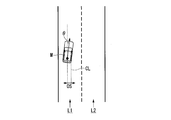
- FIG. 3 is a diagram illustrating a state in which the vehicle position recognition unit 140 recognizes the relative position of the vehicle M with respect to the travel lane L1.
- the own vehicle position recognition unit 140 makes a deviation OS of the reference point (for example, the center of gravity) of the own vehicle M from the travel lane center CL and a line connecting the travel lane center CL in the traveling direction of the own vehicle M.
- the angle ⁇ is recognized as a relative position of the host vehicle M with respect to the traveling lane L1.
- the host vehicle position recognition unit 140 recognizes the position of the reference point of the host vehicle M with respect to any side end of the host lane L1 as the relative position of the host vehicle M with respect to the traveling lane. Also good.
- the relative position of the host vehicle M recognized by the host vehicle position recognition unit 140 is provided to the target lane determination unit 110.
- the external environment recognition unit 142 recognizes the position, speed, acceleration, and other states of surrounding vehicles based on information input from the finder 20, the radar 30, the camera 40, and the like.
- the peripheral vehicle is, for example, a vehicle that travels around the host vehicle M and travels in the same direction as the host vehicle M.
- the position of the surrounding vehicle may be represented by a representative point such as the center of gravity or corner of the other vehicle, or may be represented by a region expressed by the contour of the other vehicle.
- the “state” of the surrounding vehicle may include the acceleration of the surrounding vehicle, whether the lane is changed (or whether the lane is going to be changed), which is grasped based on the information of the various devices.
- the external environment recognition unit 142 may recognize the positions of guardrails, utility poles, parked vehicles, pedestrians, and other objects.
- the action plan generation unit 144 sets a starting point of automatic driving and / or a destination of automatic driving.
- the starting point of the automatic driving may be the current position of the host vehicle M or a point where an operation for instructing automatic driving is performed.
- the action plan generation unit 144 generates an action plan in a section between the start point and the destination for automatic driving. In addition, not only this but the action plan production
- the action plan is composed of a plurality of events that are executed sequentially, for example.
- Examples of the event include a deceleration event for decelerating the host vehicle M, an acceleration event for accelerating the host vehicle M, a lane keeping event for driving the host vehicle M so as not to deviate from the traveling lane, and a lane change event for changing the traveling lane.
- a merging event that changes the driving lane, shifts from the manual driving mode to the automatic driving mode at the start point of the automatic driving, or manually from the automatic driving mode at the scheduled end point of the automatic driving
- a handover event or the like for shifting to the operation mode is included.
- the action plan generation unit 144 sets a lane change event, a branch event, or a merge event at a location where the target lane determined by the target lane determination unit 110 is switched.
- Information indicating the action plan generated by the action plan generation unit 144 is stored in the storage unit 180 as action plan information 186.
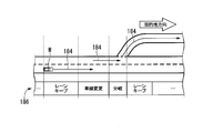
- FIG. 4 is a diagram showing an example of an action plan generated for a certain section.
- the action plan generation unit 144 generates an action plan necessary for the host vehicle M to travel on the target lane indicated by the target lane information 184.
- the action plan generation unit 144 may dynamically change the action plan regardless of the target lane information 184 according to a change in the situation of the host vehicle M.
- the action plan generation unit 144 may determine that the speed of the surrounding vehicle recognized by the external recognition unit 142 exceeds the threshold while the vehicle travels, or the movement direction of the surrounding vehicle traveling in the lane adjacent to the own lane is the own lane direction.
- the event set in the driving section where the host vehicle M is scheduled to travel is changed.
- the vehicle from the rear of the lane to which the lane is changed becomes greater than the threshold during the lane keep event according to the recognition result of the external recognition unit 142.
- the action plan generation unit 144 may change the event next to the lane keep event from a lane change event to a deceleration event, a lane keep event, or the like. As a result, the vehicle control system 100 can automatically drive the host vehicle M safely even when a change occurs in the external environment.
- FIG. 5 is a diagram illustrating an example of the configuration of the trajectory generation unit 146.
- the track generation unit 146 includes, for example, a travel mode determination unit 146A, a track candidate generation unit 146B, and an evaluation / selection unit 146C.
- the travel mode determination unit 146A determines one of the travel modes such as constant speed travel, follow-up travel, low-speed follow-up travel, deceleration travel, curve travel, and obstacle avoidance travel. .
- the traveling mode determination unit 146A determines that the traveling mode is constant speed traveling when there is no other vehicle ahead of the host vehicle M.
- the traveling mode determination unit 146A determines the traveling mode to follow running when traveling following the preceding vehicle.
- the traveling mode determination unit 146A determines the traveling mode as low-speed following traveling in a traffic jam scene or the like.
- the travel mode determination unit 146A determines the travel mode to be decelerated when the outside recognition unit 142 recognizes the deceleration of the preceding vehicle or when an event such as stopping or parking is performed. In addition, when the outside recognition unit 142 recognizes that the host vehicle M has reached a curved road, the travel mode determination unit 146A determines the travel mode to be curved travel. In addition, the travel mode determination unit 146A determines the travel mode to be obstacle avoidance travel when the external environment recognition unit 142 recognizes an obstacle in front of the host vehicle M. In addition, when executing a lane change event, an overtaking event, a branching event, a merging event, a handover event, and the like, the traveling mode determination unit 146A determines a traveling mode according to each event.
- the trajectory candidate generation unit 146B generates trajectory candidates based on the travel mode determined by the travel mode determination unit 146A.
- FIG. 6 is a diagram illustrating an example of trajectory candidates generated by the trajectory candidate generation unit 146B.
- FIG. 6 shows candidate tracks generated when the host vehicle M changes lanes from the lane L1 to the lane L2.
- the trajectory candidate generation unit 146B takes a trajectory as shown in FIG. 6, for example, a target trajectory point (trajectory point K) at which a predetermined position (for example, the center of gravity or the center of the rear wheel axis) of the host vehicle M should arrive at a predetermined time in the future. ).
- FIG. 7 is a diagram in which trajectory candidates generated by the trajectory candidate generation unit 146B are expressed by trajectory points K.
- the trajectory candidate generation unit 146B gradually widens the distance between the trajectory points K when it wants to accelerate and gradually narrows the distance between the trajectory points when it wants to decelerate.
- the trajectory candidate generation unit 146B needs to give a target speed to each of the trajectory points K.
- the target speed is determined according to the travel mode determined by the travel mode determination unit 146A.
- the track candidate generation unit 146B first sets a lane change target position (or a merge target position).
- the lane change target position is set as a relative position with respect to the surrounding vehicles, and determines “with which surrounding vehicle the lane is to be changed”.
- the trajectory candidate generation unit 146B pays attention to three surrounding vehicles with the lane change target position as a reference, and determines a target speed when the lane change is performed.
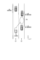
- FIG. 8 is a diagram illustrating the lane change target position TA. In the figure, L1 represents the own lane and L2 represents the adjacent lane.
- the preceding vehicle mA is set as the surrounding vehicle that runs immediately before the own vehicle M
- the front reference vehicle mB and the lane change target position TA is set as the surrounding vehicle that runs immediately before the lane changing target position TA.
- a surrounding vehicle traveling immediately after is defined as a rear reference vehicle mC.
- the host vehicle M needs to perform acceleration / deceleration in order to move to the side of the lane change target position TA.
- the trajectory candidate generation unit 146B predicts the future state of the three neighboring vehicles and determines the target speed so as not to interfere with each neighboring vehicle.
- FIG. 9 is a diagram showing a speed generation model when the speeds of the three surrounding vehicles are assumed to be constant.
- straight lines extending from mA, mB, and mC indicate displacements in the traveling direction when it is assumed that the respective surrounding vehicles have traveled at a constant speed.
- the own vehicle M must be between the front reference vehicle mB and the rear reference vehicle mC at the point CP at which the lane change is completed, and must be behind the preceding vehicle mA before that.
- the track candidate generation unit 146B derives a plurality of time-series patterns of the target speed until the lane change is completed. Then, a plurality of trajectory candidates as shown in FIG.
- the motion patterns of the three surrounding vehicles are not limited to the constant speed as shown in FIG. 9, and may be predicted on the assumption of a constant acceleration and a constant jerk (jumping degree).
- the evaluation / selection unit 146C evaluates the candidate track generated by the track candidate generation unit 146B from two viewpoints of planability and safety, and selects a target track to be output to the travel control unit 160.
- the track is highly evaluated when the followability with respect to an already generated plan (for example, an action plan) is high and the total length of the track is short.
- an action plan for example, when it is desired to change the lane in the right direction, a trajectory in which the lane is once changed in the left direction and returned is evaluated as low.
- viewpoint of safety for example, at each track point, the distance between the host vehicle M and the object (peripheral vehicle or the like) is longer, and the higher the acceleration / deceleration or the change amount of the steering angle, the higher the evaluation.
- the switching control unit 150 switches between the automatic operation mode and the manual operation mode based on a signal input from the changeover switch 80. Further, the switching control unit 150 switches from the automatic operation mode to the manual operation mode based on an operation for instructing the operation device 70 to accelerate, decelerate, or steer. For example, the switching control unit 150 switches from the automatic operation mode to the manual operation mode (override) when the state in which the operation amount indicated by the signal input from the operation device 70 exceeds the threshold value continues for a reference time or longer. Further, the switching control unit 150 may return to the automatic operation mode when an operation on the operation device 70 is not detected for a predetermined time after switching to the manual operation mode by the override.
- the traveling control unit 160 includes, for example, an acceleration / deceleration control unit 162 and a steering angle control unit 164 as shown in FIG.
- the traveling control unit 160 includes the traveling driving force output device 200, the steering so that the host vehicle M passes through the track generated by the track candidate generating unit 146B at a scheduled time (time associated with the track point).
- the device 210 and the brake device 220 are controlled.
- the steering angle control unit 164 is described as a part of the travel control unit 160, but the steering angle control unit 164 may be a part of the track generation unit 146.
- FIG. 10 is a diagram showing the relationship between the acceleration / deceleration control unit 162 and the steering angle control unit 164 and their controlled objects.
- the acceleration / deceleration control unit 162 and the steering angle control unit 164 are supplied with the target track from the track generation unit 146 in the automatic driving control unit 120, and the position of the host vehicle specified by the navigation device 50 and the host vehicle position recognition unit 140. Is supplied.
- the acceleration / deceleration control unit 162 controls the travel driving force output device 200 and the brake device 220 based on the target track acquired from the automatic driving control unit 120 and the position of the host vehicle M.
- the steering angle control unit 164 controls the steering device 210 based on the target track acquired from the automatic driving control unit 120 and the position of the host vehicle M.
- FIG. 11 is a diagram illustrating an example of the function of the steering angle control unit 164.
- the steering angle control unit 164 includes, for example, a processing unit 165, a gaze position deriving unit 170, a first steering angle deriving unit 172, a second steering angle deriving unit 174, and an integrating unit 176.
- the processing unit 165 includes a first storage unit 166, a determination unit 167, a second storage unit 168, and an application unit 169 (post-stop target track generation unit).
- the first storage unit 166 stores the target track information and the position information of the host vehicle M output from the automatic operation control unit 120 under the control of the processing unit 165.
- the first storage unit 166 is a buffer in which information is temporarily stored, for example.
- the first storage unit 166 includes an interface that communicates with the automatic operation control unit 120 and a storage device such as a RAM.
- the target trajectory information output from the automatic driving control unit 120 is a part of the target trajectory information generated by the automatic driving control unit 120. For example, when the target trajectory is generated (for example, for 9 seconds) by the automatic operation control unit 120, the part is information on the target trajectory that is smaller (for example, for 3 seconds).
- the processing unit 165 for example, information on the target trajectory generated for each processing cycle of the trajectory generation unit 146 is stored. For example, when the processing unit 165 acquires a new target trajectory that is different from the existing target trajectory, the processing unit 165 overwrites the existing target trajectory information and accumulates the newly acquired target trajectory information in the first storage unit 166. . For example, when the processing unit 165 acquires the target trajectory generated in the next processing cycle from the automatic operation control unit 120, the processing unit 165 discards the stored target trajectory of the previous processing cycle and newly acquires the target of the processing cycle. The trajectory is stored in the first storage unit 166.
- the first storage unit 166 stores, for example, information on a target track whose total length is a predetermined speed (for example, 3 m) or more and whose speed of the host vehicle M instructed by the automatic operation control unit 120 is a predetermined speed (for example, 2 m / s) or more. Is done. For example, when the processing unit 165 acquires information on a target trajectory that does not satisfy the above-described conditions, the processing unit 165 does not store the target trajectory in the storage area of the first storage unit 166.
- the target track that does not meet the above-described conditions is, for example, a target track immediately before the host vehicle M stops. In this case, the subsequent processing is executed based on the target trajectory of the previous processing cycle stored in the storage area.
- the determination unit 167 predicts whether or not the host vehicle M stops based on the target track stored in the storage area of the first storage unit 166 (determines whether or not the host vehicle M is about to stop). ). When it is predicted that the host vehicle M will stop, the determination unit 167 stores the information stored in the storage area of the first storage unit 166 in the second storage unit 168.
- the second storage unit 168 has a storage area for storing information. In the second storage unit 168, for example, the information stored in the first storage unit 166 is saved and stored before being overwritten with other information.
- the second storage unit 168 includes a storage device such as a RAM.
- the application unit 169 generates a fitting trajectory (post-stop target trajectory) using the information stored in the second storage unit 168 and the n-order function.
- “N” is an arbitrary natural number.
- the fitting trajectory is a trajectory that is generated when the host vehicle M is predicted to stop by the determination unit 167, and is a trajectory that is assumed to travel when the host vehicle M resumes traveling after the vehicle stops. Details will be described later.
- the gaze position deriving unit 170 derives the gaze position.
- FIG. 12 is a conceptual diagram of control executed when the host vehicle M is predicted to stop.
- the gaze position deriving unit 170 derives the gaze position on the fitting trajectory generated by the application unit 169.
- the gaze position deriving unit 170 derives the gaze position on the target track.
- the first steering angle deriving unit 172 has a tangent along the traveling direction of the host vehicle M, and controls the steering of the host vehicle M based on a virtual arc passing through the gaze position and the position of the host vehicle M.
- the traveling direction of the host vehicle M may be the direction of the central axis of the vehicle, or may be the direction in which the speed vector of the host vehicle M at that moment is directed.
- FIG. 13 is a diagram for explaining the steering angle deriving process by the first steering angle deriving unit 172.
- FIG. 13A shows the flow of the first steering angle derivation process
- FIG. 13B shows the transition of the position of the host vehicle.
- the first steering angle deriving unit 172 assumes that the host vehicle M turns on a predetermined steady circle.
- a steady circle is, for example, a turning trajectory when traveling with the steering wheel rolling to a certain turning angle.
- the first steering angle deriving unit 172 includes the position of the host vehicle M at the time t (current position; x0, y0), the position of the host vehicle M at the time t + 1 (x1, y1), and the host vehicle at the time t + 2.
- the position (x2, y2) of the vehicle M is derived.
- one of the positions of the host vehicle M at time t + 1 and time t + 2 is the gaze position derived by the gaze position deriving unit 170.
- the first steering angle deriving unit 172 assumes that a steady circle passing through the above-described three points of the host vehicle M turns at a certain time, and derives the curvature of the steady circle.
- the first steering angle deriving unit 172 regards the host vehicle M as turning in a steady circle in a steady state, and derives the steering angle of the host vehicle M based on the following equation (1).
- ⁇ is a steering wheel angle
- k is a curvature of a steady circle
- A is a stability factor
- V is a vehicle speed
- L is a wheel base
- n is a gear ratio.
- the steering angle is indicated by an absolute value, for example, and the same applies to the following description.
- ⁇ k ⁇ (1 + A ⁇ V 2 ) ⁇ L ⁇ n (1)
- the first steering angle deriving unit 172 includes the position of the host vehicle M at the time t (current position; x0, y0), the position of the host vehicle M at the time t-1 (-x1, -y1),
- the curvature may be derived using a stationary circle that passes through the gaze position.
- the first steering angle deriving unit 172 may limit the steering control of the host vehicle M by correcting the curvature of the arc to a predetermined value or less.
- An arc is a part of the circumference of a stationary circle.
- the second steering angle deriving unit 174 derives a second steering angle that increases the steering control of the host vehicle M as the deviation between the gaze position in the direction orthogonal to the traveling direction of the host vehicle M and the position of the host vehicle M increases. To do.
- FIG. 14 is a conceptual diagram for deriving the second steering angle by the second steering angle deriving unit 174.
- FIG. 14A shows the flow of the second steering angle derivation process
- FIG. 14B shows how the second steering angle is derived.
- the second steering angle deriving unit 174 derives a lateral shift G between the gaze position OP on the target track KL and the position of the host vehicle M in a direction orthogonal to the traveling direction of the host vehicle M.
- the gaze position OP is a position where the host vehicle M exists after Tref seconds on the target track, which is derived by the gaze position deriving unit 170.
- the second steering angle deriving unit 174 derives an index value based on a function using the deviation G and the vehicle speed as parameters, and derives a new index value by adding a coefficient K to the derived index value.
- the second steering angle deriving unit 174 derives the second steering angle based on the derived new index value and the vehicle speed.
- the second steering angle deriving unit 174 may limit the steering control of the host vehicle M when the deviation G is greater than or equal to a predetermined value, or when the second steering angle is greater than or equal to the predetermined angle.
- the second steering angle deriving unit 174 can suppress the host vehicle M from turning sharply.
- the integration unit 176 integrates the first steering angle and the second steering angle to derive the steering angle output to the steering device 210.
- the integration unit 176 may change the weighting for the first steering angle and the second steering angle according to the vehicle speed. Specifically, the integration unit 176 increases the weighting of the first steering angle with respect to the weighting of the second steering angle when the vehicle speed is low (for example, the vehicle speed is equal to or lower than the first predetermined speed). This is because the first steering angle derived based on the arc has a small error at a low vehicle speed.
- the first steering angle deviation can be compensated by increasing the weighting of the second steering angle relative to the weighting of the first steering angle.
- the steering angle control unit 164 acquires a part of the information of the target track generated by the track generation unit 146.
- the steering angle control unit 164 cannot recognize the behavior (destination) of the host vehicle M after the stop.
- the steering angle control unit 164 may not be able to suitably control the steering so that the behavior of the host vehicle M is smoothly performed when starting from the stop.
- the steering angle control unit 164 of the present embodiment derives the steering angle based on the fitting trajectory FR, and controls the steering based on the derived steering angle, so that the host vehicle M starts from stopping.
- the steering can be suitably controlled so that the behavior of the host vehicle M is smoothly performed. More specific description will be given below.
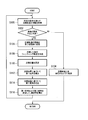
- FIG. 15 is a flowchart showing a flow of processing executed by the steering angle control unit 164. This processing is executed every processing cycle of the trajectory generation unit 146. Each process of FIG. 15 will be described with reference to FIGS. 16 to 18.
- the processing unit 165 acquires a target trajectory that satisfies a predetermined condition from the automatic operation control unit 120, and stores the acquired information in the first storage unit 166 (step S100).
- the determination unit 167 predicts whether or not the host vehicle M stops based on the acquired target track (determines whether or not the host vehicle M is about to stop) (step S102).
- the steering angle control unit 164 controls the steering so as to travel on the target track (step S104).
- the first steering angle deriving unit 172, the second steering angle deriving unit 174, and the integrating unit 176 control the steering angle by executing the processing described above.
- FIG. 16 is a diagram for explaining the processing of the determination unit 167.
- the upper part of FIG. 16A shows the target trajectory information D and the first storage information D * generated by the trajectory generator 146 at time t.
- the first storage information D * is information acquired by the first storage unit 166 and is a part of the information D of the target trajectory KL.
- the lower diagram of FIG. 16A shows the position (x0, y0) of the host vehicle M at time t and the positions (x1, y1) to (x3, y3) of the host vehicle M in the future.
- FIG. 16B shows the target trajectory information D generated by the trajectory generator 146 and the first storage information D * at time t + 1.
- the lower part of FIG. 16B shows the position (x0 #, y0 #) of the host vehicle M at time t + 1, and the positions (x1 #, y1 #) and (x2 #, y2 #) of the host vehicle M in the future. ing.
- FIG. 16C shows the target trajectory information D and the first storage information D * generated by the trajectory generator 146 at time t + 3.
- the lower part of FIG. 16C shows the position (x0 ##, y0 ##) of the host vehicle M at time t + 3. Note that illustration of the target track information D, the first storage information D *, and the position of the host vehicle M at time t + 2 is omitted.
- the determination unit 167 predicts that the host vehicle M stops when there is no change in the position of the host vehicle M at successive times in the first storage information D *, for example.
- the host vehicle M since the position of the host vehicle M at the time t + 3 and the time t + 4 of the first stored information D * does not change at the time t + 1, the host vehicle M is predicted to stop. In this case, as shown in FIG. 16C, the host vehicle M stops at time t + 3. For example, the following processing is executed before the host vehicle M stops. Note that the determination unit 167 may predict that the host vehicle M stops when there are three or more times when the position of the host vehicle M does not change.
- the determination unit 167 stores the first storage information D * stored in the first storage unit 166 in the second storage unit 168 (step S106).
- the application unit 169 generates the fitting trajectory FR using the first storage information D * stored in the second storage unit 168 (step S108).
- the fitting trajectory is a trajectory obtained by estimating a target trajectory after the host vehicle M has started in a state where the host vehicle M has stopped and a target trajectory has not been obtained.
- the fitting trajectory is considered as a trajectory extending from the end of the target trajectory, and in other situations, for example, when the host vehicle M is behind the target track, or when the host vehicle M is advanced from the target track, It may be generated when the target track does not exist in the traveling direction of the host vehicle M, such as when the vehicle M is located at the end of the target track.
- FIG. 17 is a diagram for describing processing for generating the fitting trajectory FR.
- the application unit 169 derives an n-order function, an ellipse, a circle, or the like that fits the target trajectory KL stored in the second storage unit 168.
- the application unit 169 derives a function closest to the target trajectory KL stored in the second storage unit 168 by a method such as a least square method while fixing n and changing the parameter of the n-order function.
- the application unit 169 generates the fitting trajectory FR by applying the derived n-order function to the front side of the host vehicle M.
- FIG. 18 is a diagram for describing processing for deriving a gaze position.
- the gaze position deriving unit 170 derives the travel distance that travels in the Tref seconds on the fitting track FR based on the speed of the host vehicle M.
- the gaze position deriving unit 170 derives, as the gaze position OP, a position where the host vehicle M exists (or a position when traveling a predetermined distance; the same applies hereinafter) on the fitting trajectory FR after Tref seconds.
- the second steering angle deriving unit 174 derives the second steering angle based on the lateral deviation (deviation) between the host vehicle M and the gaze position OP (step S114).
- the integration unit 176 integrates the first steering angle and the second steering angle to derive a steering angle used for control (step S116).
- the steering device 210 is controlled with the steering angle derived by reflecting the fitting track FR during deceleration.
- the host vehicle M can stop in a state where the steering direction is matched with the direction estimated to travel after the start. Thereby, the process of this flowchart is complete
- the integration unit 176 may derive the steering angle by adding the first steering angle and the second steering angle, or weight each of the first steering angle and the second steering angle to obtain a weighted sum. By obtaining the steering angle. Further, when the derived steering angle exceeds a predetermined angle, the integration unit 176 may limit the steering angle to a predetermined angle or less.
- the first steering angle deriving unit 172 has derived the first steering angle and the second steering angle deriving unit 174 has derived the second steering angle based on the fitting trajectory.
- the steering angle control unit 164 acquires information on the target track in front of the stop position of the host vehicle M (the target track is Based on the acquired (existing) target trajectory
- the first steering angle deriving unit 172 derives the first steering angle
- the second steering angle deriving unit 174 calculates the second steering angle. It may be derived.
- the integration unit 176 integrates the derived first steering angle and second steering angle based on the target trajectory to derive the steering angle used for control.
- FIG. 19 is a diagram illustrating an example of how the host vehicle M is controlled by the processing of the present embodiment. For example, it is a diagram showing in detail the state of the host vehicle M at time t + 3 in FIG.
- FIG. 19A shows the behavior of the host vehicle M when the present embodiment is not applied
- FIG. 19B shows the behavior of the host vehicle M when the present embodiment is applied.
- the steering component may be lost from the target trajectory, resulting in a trajectory for stopping linearly.
- the loss of the steering component means that the steering angle is zero (neutral).
- the vehicle when the vehicle is restarted after the vehicle stops on a curved road, the vehicle may be started in a state where the steering angle is near zero. In this case, the host vehicle M may need to be steered suddenly after starting.
- the steering angle of the host vehicle M is controlled by reflecting the fitting track FR when the vehicle is stopped.
- the fitting trajectory FR is also estimated to maintain the steering angle, so that the steering is suddenly performed after starting. It is likely that no need will arise. As a result, the host vehicle M can travel smoothly before and after stopping.
- the vehicle control system 100 when it is predicted by the determination unit 167 that the host vehicle M is to be stopped, the vehicle control system 100 is based on the target track before the host vehicle M stops. A fitting trajectory after the vehicle stops is generated. Then, the vehicle control system 100 controls the host vehicle M based on the steering angle derived by deriving the steering angle based on the gaze position OP of the fitting trajectory FR. As a result, the steering angle at the time of starting after the vehicle stops can be suitably controlled.
- FIG. 20 is a diagram illustrating an example of the function of the steering angle control unit 164A of the second embodiment.
- the steering angle control unit 164A includes a processing unit 165, a gaze position deriving unit 170, and a steering angle deriving unit 173.
- the processing unit 165, the gaze position deriving unit 170, and the steering angle deriving unit 173 have functions equivalent to the processing unit 165, the gaze position deriving unit 170, and the first steering angle deriving unit 172 of the first embodiment, respectively.
- a description will be given focusing on differences from the first embodiment.
- FIG. 21 is a flowchart showing a flow of processing executed by the steering angle control unit 164A.
- the processing unit 165 acquires a target trajectory that satisfies a predetermined condition from the automatic operation control unit 120, and stores the acquired information in the first storage unit 166 (step S200).
- the determination unit 167 predicts whether or not the own vehicle M stops based on the acquired target track (determines whether or not the own vehicle M is about to stop) (step S202).
- the steering angle control unit 164 controls the steering so as to travel on the target track (step S204).
- the determination unit 167 stores the first storage information D * stored in the first storage unit 166 in the second storage unit 168 (step S206).
- the application unit 169 generates the fitting trajectory FR using the first storage information D * stored in the second storage unit 168 (step S208).
- the gaze position deriving unit 170 sets a gaze position on the fitting trajectory FR (step S210).
- the steering angle deriving unit 173 derives the steering angle using the gaze position (step S212). Thereby, the process of this flowchart is complete
- the steering angle when starting after the vehicle stops is preferably reduced while reducing the processing load. Can do.
- the vehicle control system 100 determines whether or not the vehicle stops based on a track generation unit that generates a target track of the vehicle and the target track generated by the track generation unit. And a post-stop target track that generates a post-stop target track after the vehicle stops based on the target track before the vehicle stops when the determination unit determines that the vehicle is to stop.
- the generation unit it is possible to suitably control the steering angle when starting after the vehicle stops.
- Acceleration / Deceleration Control Unit 164 ... Steering Angle Control Unit, 165 ... Processing Unit, 166 ... First Storage unit, 167 ... determination unit, 168 ... second storage unit, 169 ... application unit, 170 ... gaze position deriving unit, 172 ... first steering angle deriving unit, 174 ... second steering angle deriving unit 176 ... integrating unit, 180 ... storage unit, 200 ... driving force output unit, 210 ... steering device, 220 ... braking system, M ... vehicle
Landscapes
- Engineering & Computer Science (AREA)
- Transportation (AREA)
- Mechanical Engineering (AREA)
- Automation & Control Theory (AREA)
- Human Computer Interaction (AREA)
- Combustion & Propulsion (AREA)
- Chemical & Material Sciences (AREA)
- Physics & Mathematics (AREA)
- Remote Sensing (AREA)
- General Physics & Mathematics (AREA)
- Radar, Positioning & Navigation (AREA)
- Aviation & Aerospace Engineering (AREA)
- Control Of Driving Devices And Active Controlling Of Vehicle (AREA)
- Traffic Control Systems (AREA)
- Steering Control In Accordance With Driving Conditions (AREA)
- Regulating Braking Force (AREA)
Abstract
L'invention concerne un système de commande de véhicule qui comprend : une unité de génération de trajectoire qui génère une trajectoire cible d'un véhicule ; une unité de détermination qui, sur la base de la trajectoire cible générée par l'unité de génération de trajectoire, détermine si le véhicule tente de s'arrêter ; et une unité de génération de trajectoire cible post-arrêt qui, si l'unité de détermination détermine que le véhicule tente de s'arrêter, génère, sur la base de la trajectoire cible avant que le véhicule ne s'arrête, une trajectoire cible post-arrêt après que le véhicule s'est arrêté.
Priority Applications (3)
| Application Number | Priority Date | Filing Date | Title |
|---|---|---|---|
| JP2018520761A JP6598127B2 (ja) | 2016-05-31 | 2017-05-12 | 車両制御システム、車両制御方法、および車両制御プログラム |
| US16/305,103 US20200317196A1 (en) | 2016-05-31 | 2017-05-12 | Vehicle control system, vehicle control method and vehicle control program |
| CN201780032839.5A CN109195845B (zh) | 2016-05-31 | 2017-05-12 | 车辆控制系统、车辆控制方法及存储介质 |
Applications Claiming Priority (2)
| Application Number | Priority Date | Filing Date | Title |
|---|---|---|---|
| JP2016-108528 | 2016-05-31 | ||
| JP2016108528 | 2016-05-31 |
Publications (1)
| Publication Number | Publication Date |
|---|---|
| WO2017208781A1 true WO2017208781A1 (fr) | 2017-12-07 |
Family
ID=60477835
Family Applications (1)
| Application Number | Title | Priority Date | Filing Date |
|---|---|---|---|
| PCT/JP2017/018007 Ceased WO2017208781A1 (fr) | 2016-05-31 | 2017-05-12 | Système de commande de véhicule, procédé de commande de véhicule et programme de commande de véhicule |
Country Status (4)
| Country | Link |
|---|---|
| US (1) | US20200317196A1 (fr) |
| JP (1) | JP6598127B2 (fr) |
| CN (1) | CN109195845B (fr) |
| WO (1) | WO2017208781A1 (fr) |
Cited By (8)
| Publication number | Priority date | Publication date | Assignee | Title |
|---|---|---|---|---|
| JP2019171970A (ja) * | 2018-03-27 | 2019-10-10 | トヨタ自動車株式会社 | 車両制御システム |
| JP2020157847A (ja) * | 2019-03-25 | 2020-10-01 | 株式会社Subaru | 自動操舵制御装置 |
| JP2021126925A (ja) * | 2020-02-12 | 2021-09-02 | 株式会社Subaru | 制御装置、制御方法およびプログラム |
| JP2021126926A (ja) * | 2020-02-12 | 2021-09-02 | 株式会社Subaru | 制御装置、制御方法およびプログラム |
| CN116080679A (zh) * | 2022-12-01 | 2023-05-09 | 北京踏歌智行科技有限公司 | 一种面向井下巷道的无轨胶轮车无人驾驶方法 |
| JP2023094482A (ja) * | 2021-12-23 | 2023-07-05 | ロベルト・ボッシュ・ゲゼルシャフト・ミト・ベシュレンクテル・ハフツング | 処理装置および処理方法 |
| WO2025047673A1 (fr) * | 2023-08-29 | 2025-03-06 | 株式会社デンソー | Dispositif, procédé et programme de commande |
| DE112024002678T5 (de) | 2023-09-21 | 2026-04-30 | Robert Bosch Gesellschaft mit beschränkter Haftung | Steuervorrichtung und Steuerverfahren |
Families Citing this family (16)
| Publication number | Priority date | Publication date | Assignee | Title |
|---|---|---|---|---|
| JP7206750B2 (ja) * | 2018-09-26 | 2023-01-18 | 日本電気株式会社 | 運転支援装置 |
| WO2020064800A1 (fr) * | 2018-09-26 | 2020-04-02 | Zf Friedrichshafen Ag | Dispositif pour surveiller un environnement d'un véhicule |
| JP7163729B2 (ja) * | 2018-11-08 | 2022-11-01 | トヨタ自動車株式会社 | 車両制御装置 |
| WO2020152977A1 (fr) * | 2019-01-21 | 2020-07-30 | 日立オートモティブシステムズ株式会社 | Dispositif de commande de véhicule, procédé de commande de véhicule et système de commande de véhicule |
| JP7123840B2 (ja) * | 2019-03-19 | 2022-08-23 | 本田技研工業株式会社 | 車両制御装置、監視システム、車両制御方法、およびプログラム |
| JP7121714B2 (ja) * | 2019-09-17 | 2022-08-18 | 本田技研工業株式会社 | 車両制御システム |
| DE112020005320T5 (de) * | 2020-01-10 | 2022-11-10 | Hitachi Astemo, Ltd. | Sensorausrichtungseinrichtung, fahrsteuersystem und korrekturbetragschätzverfahren |
| JP7487994B2 (ja) * | 2020-04-17 | 2024-05-21 | 株式会社Subaru | 車両の運転支援装置。 |
| KR20220033077A (ko) * | 2020-09-07 | 2022-03-16 | 주식회사 라이드플럭스 | 속력 프로파일을 이용한 자율주행 차량의 정지 제어 방법, 장치 및 컴퓨터프로그램 |
| JP6970264B1 (ja) * | 2020-10-06 | 2021-11-24 | 株式会社Nichijo | 車両 |
| CN112389465B (zh) * | 2020-11-17 | 2022-03-18 | 湖南三一智能控制设备有限公司 | 工程车辆的控制方法、控制系统和工程车辆 |
| KR20220086781A (ko) * | 2020-12-16 | 2022-06-24 | 현대모비스 주식회사 | 차량의 타겟 감지방법 및 시스템 |
| CN113291322B (zh) * | 2021-06-18 | 2022-07-05 | 上海华兴数字科技有限公司 | 自动驾驶轨迹偏差检测方法、系统及自动驾驶车辆 |
| CN113997953A (zh) * | 2021-11-24 | 2022-02-01 | 上海网车科技有限公司 | 一种匝道自动汇车辅助驾驶系统及匝道自动汇车方法 |
| US12481428B2 (en) * | 2022-01-24 | 2025-11-25 | Samsung Electronics Co., Ltd. | Storage device and a method of operating the storage device, and a vehicle including the storage device |
| DE102024200245A1 (de) * | 2024-01-11 | 2025-07-17 | Volkswagen Aktiengesellschaft | Verfahren und Vorrichtung zur Längsführung eines Kraftfahrzeugs |
Citations (7)
| Publication number | Priority date | Publication date | Assignee | Title |
|---|---|---|---|---|
| JP2002319100A (ja) * | 2001-04-20 | 2002-10-31 | Honda Motor Co Ltd | 車両の軌跡推定装置及びこれを用いた車両の走行安全装置 |
| JP2006085524A (ja) * | 2004-09-17 | 2006-03-30 | Honda Motor Co Ltd | 車両用走行軌跡推定装置 |
| JP2006123597A (ja) * | 2004-10-26 | 2006-05-18 | Nissan Motor Co Ltd | 車両用操向装置 |
| WO2008117447A1 (fr) * | 2007-03-27 | 2008-10-02 | Pioneer Corporation | Dispositif de réception, procédé de réception, programme de réception, et support d'enregistrement |
| JP2008308032A (ja) * | 2007-06-14 | 2008-12-25 | Toyota Motor Corp | 車両制御装置 |
| JP2009276193A (ja) * | 2008-05-14 | 2009-11-26 | Navitime Japan Co Ltd | ナビゲーションシステム、経路探索サーバおよび経路案内方法ならびに端末装置 |
| JP2015095721A (ja) * | 2013-11-11 | 2015-05-18 | 株式会社デンソー | 家電遠隔制御システム、車載装置 |
Family Cites Families (6)
| Publication number | Priority date | Publication date | Assignee | Title |
|---|---|---|---|---|
| JP2952816B2 (ja) * | 1996-12-17 | 1999-09-27 | 本田技研工業株式会社 | 車両の自動操舵装置 |
| US9045144B2 (en) * | 2013-05-09 | 2015-06-02 | Robert Bosch Gmbh | Third-order polynomial-based course prediction for driver assistance functions |
| JP6103049B2 (ja) * | 2013-05-22 | 2017-03-29 | 日産自動車株式会社 | 駐車支援装置および駐車支援方法 |
| DE102013214805A1 (de) * | 2013-07-29 | 2015-01-29 | Bayerische Motoren Werke Aktiengesellschaft | Entscheiden über die Fahrtrichtung beim Wiederanfahren bei einem automatisierten Parkvorgang mit einem Parkassistenzsystem |
| KR101877553B1 (ko) * | 2014-11-14 | 2018-07-11 | 한국전자통신연구원 | 차량 자율주행 시스템 및 이를 이용한 차량 주행 방법 |
| JP6655455B2 (ja) * | 2016-04-18 | 2020-02-26 | 日立オートモティブシステムズ株式会社 | 走行制御装置 |
-
2017
- 2017-05-12 WO PCT/JP2017/018007 patent/WO2017208781A1/fr not_active Ceased
- 2017-05-12 US US16/305,103 patent/US20200317196A1/en not_active Abandoned
- 2017-05-12 CN CN201780032839.5A patent/CN109195845B/zh active Active
- 2017-05-12 JP JP2018520761A patent/JP6598127B2/ja active Active
Patent Citations (7)
| Publication number | Priority date | Publication date | Assignee | Title |
|---|---|---|---|---|
| JP2002319100A (ja) * | 2001-04-20 | 2002-10-31 | Honda Motor Co Ltd | 車両の軌跡推定装置及びこれを用いた車両の走行安全装置 |
| JP2006085524A (ja) * | 2004-09-17 | 2006-03-30 | Honda Motor Co Ltd | 車両用走行軌跡推定装置 |
| JP2006123597A (ja) * | 2004-10-26 | 2006-05-18 | Nissan Motor Co Ltd | 車両用操向装置 |
| WO2008117447A1 (fr) * | 2007-03-27 | 2008-10-02 | Pioneer Corporation | Dispositif de réception, procédé de réception, programme de réception, et support d'enregistrement |
| JP2008308032A (ja) * | 2007-06-14 | 2008-12-25 | Toyota Motor Corp | 車両制御装置 |
| JP2009276193A (ja) * | 2008-05-14 | 2009-11-26 | Navitime Japan Co Ltd | ナビゲーションシステム、経路探索サーバおよび経路案内方法ならびに端末装置 |
| JP2015095721A (ja) * | 2013-11-11 | 2015-05-18 | 株式会社デンソー | 家電遠隔制御システム、車載装置 |
Cited By (11)
| Publication number | Priority date | Publication date | Assignee | Title |
|---|---|---|---|---|
| JP2019171970A (ja) * | 2018-03-27 | 2019-10-10 | トヨタ自動車株式会社 | 車両制御システム |
| JP2020157847A (ja) * | 2019-03-25 | 2020-10-01 | 株式会社Subaru | 自動操舵制御装置 |
| JP7216589B2 (ja) | 2019-03-25 | 2023-02-01 | 株式会社Subaru | 自動操舵制御装置 |
| JP2021126925A (ja) * | 2020-02-12 | 2021-09-02 | 株式会社Subaru | 制御装置、制御方法およびプログラム |
| JP2021126926A (ja) * | 2020-02-12 | 2021-09-02 | 株式会社Subaru | 制御装置、制御方法およびプログラム |
| JP7333763B2 (ja) | 2020-02-12 | 2023-08-25 | 株式会社Subaru | 制御装置、制御方法およびプログラム |
| JP7333764B2 (ja) | 2020-02-12 | 2023-08-25 | 株式会社Subaru | 制御装置、制御方法およびプログラム |
| JP2023094482A (ja) * | 2021-12-23 | 2023-07-05 | ロベルト・ボッシュ・ゲゼルシャフト・ミト・ベシュレンクテル・ハフツング | 処理装置および処理方法 |
| CN116080679A (zh) * | 2022-12-01 | 2023-05-09 | 北京踏歌智行科技有限公司 | 一种面向井下巷道的无轨胶轮车无人驾驶方法 |
| WO2025047673A1 (fr) * | 2023-08-29 | 2025-03-06 | 株式会社デンソー | Dispositif, procédé et programme de commande |
| DE112024002678T5 (de) | 2023-09-21 | 2026-04-30 | Robert Bosch Gesellschaft mit beschränkter Haftung | Steuervorrichtung und Steuerverfahren |
Also Published As
| Publication number | Publication date |
|---|---|
| JP6598127B2 (ja) | 2019-10-30 |
| JPWO2017208781A1 (ja) | 2018-12-06 |
| US20200317196A1 (en) | 2020-10-08 |
| CN109195845A (zh) | 2019-01-11 |
| CN109195845B (zh) | 2022-01-07 |
Similar Documents
| Publication | Publication Date | Title |
|---|---|---|
| JP6598127B2 (ja) | 車両制御システム、車両制御方法、および車両制御プログラム | |
| JP6582319B2 (ja) | 車両制御システム、車両制御方法、および車両制御プログラム | |
| US11231719B2 (en) | Vehicle control system, vehicle control method and vehicle control program | |
| JP6569186B2 (ja) | 車両制御装置、車両制御方法、および車両制御プログラム | |
| JP6768787B2 (ja) | 車両制御システム、車両制御方法、および車両制御プログラム | |
| JP6303217B2 (ja) | 車両制御装置、車両制御方法、および車両制御プログラム | |
| JP6544878B2 (ja) | 車両制御システム、車両制御方法、および車両制御プログラム | |
| JP6344695B2 (ja) | 車両制御装置、車両制御方法、および車両制御プログラム | |
| JP6304894B2 (ja) | 車両制御装置、車両制御方法、および車両制御プログラム | |
| US20170261989A1 (en) | Vehicle control system, vehicle control method, and vehicle control program | |
| US20190039626A1 (en) | Vehicle control device, vehicle control method, and vehicle control program | |
| JPWO2017138513A1 (ja) | 車両制御装置、車両制御方法、および車両制御プログラム | |
| JP2017207984A (ja) | 交通状況推定装置、車両制御システム、経路誘導装置、交通状況推定方法、および交通状況推定プログラム | |
| JPWO2017154152A1 (ja) | 車両制御システム、車両制御方法、および車両制御プログラム | |
| JP2017165157A (ja) | 車両制御システム、車両制御方法、および車両制御プログラム | |
| JPWO2017179209A1 (ja) | 車両制御システム、車両制御方法、および車両制御プログラム | |
| JP6442771B2 (ja) | 車両制御装置、車両制御方法、および車両制御プログラム | |
| JP2017144886A (ja) | 車両制御装置、車両制御方法、および車両制御プログラム | |
| JP6270888B2 (ja) | 車両制御システム、車両制御方法、および車両制御プログラム | |
| WO2017159489A1 (fr) | Système de commande de véhicule, procédé de commande de véhicule et programme de commande de véhicule | |
| JP2017081421A (ja) | 車両制御装置、車両制御方法、および車両制御プログラム | |
| JP2017191551A (ja) | 車両制御システム、車両制御方法、および車両制御プログラム | |
| JP2017213936A (ja) | 車両制御システム、車両制御方法、および車両制御プログラム |
Legal Events
| Date | Code | Title | Description |
|---|---|---|---|
| WWE | Wipo information: entry into national phase |
Ref document number: 2018520761 Country of ref document: JP |
|
| 121 | Ep: the epo has been informed by wipo that ep was designated in this application |
Ref document number: 17806339 Country of ref document: EP Kind code of ref document: A1 |
|
| NENP | Non-entry into the national phase |
Ref country code: DE |
|
| 122 | Ep: pct application non-entry in european phase |
Ref document number: 17806339 Country of ref document: EP Kind code of ref document: A1 |