WO2017208805A1 - Dispositif de stockage et dispositif de gestion d'électricité - Google Patents
Dispositif de stockage et dispositif de gestion d'électricité Download PDFInfo
- Publication number
- WO2017208805A1 WO2017208805A1 PCT/JP2017/018313 JP2017018313W WO2017208805A1 WO 2017208805 A1 WO2017208805 A1 WO 2017208805A1 JP 2017018313 W JP2017018313 W JP 2017018313W WO 2017208805 A1 WO2017208805 A1 WO 2017208805A1
- Authority
- WO
- WIPO (PCT)
- Prior art keywords
- temperature
- detected
- power storage
- unit
- housing
- Prior art date
- Legal status (The legal status is an assumption and is not a legal conclusion. Google has not performed a legal analysis and makes no representation as to the accuracy of the status listed.)
- Ceased
Links
Images


Classifications
-
- H—ELECTRICITY
- H01—ELECTRIC ELEMENTS
- H01M—PROCESSES OR MEANS, e.g. BATTERIES, FOR THE DIRECT CONVERSION OF CHEMICAL ENERGY INTO ELECTRICAL ENERGY
- H01M10/00—Secondary cells; Manufacture thereof
- H01M10/60—Heating or cooling; Temperature control
- H01M10/65—Means for temperature control structurally associated with the cells
- H01M10/656—Means for temperature control structurally associated with the cells characterised by the type of heat-exchange fluid
- H01M10/6561—Gases
- H01M10/6563—Gases with forced flow, e.g. by blowers
-
- H—ELECTRICITY
- H01—ELECTRIC ELEMENTS
- H01M—PROCESSES OR MEANS, e.g. BATTERIES, FOR THE DIRECT CONVERSION OF CHEMICAL ENERGY INTO ELECTRICAL ENERGY
- H01M10/00—Secondary cells; Manufacture thereof
- H01M10/42—Methods or arrangements for servicing or maintenance of secondary cells or secondary half-cells
- H01M10/48—Accumulators combined with arrangements for measuring, testing or indicating the condition of cells, e.g. the level or density of the electrolyte
- H01M10/486—Accumulators combined with arrangements for measuring, testing or indicating the condition of cells, e.g. the level or density of the electrolyte for measuring temperature
-
- H—ELECTRICITY
- H01—ELECTRIC ELEMENTS
- H01M—PROCESSES OR MEANS, e.g. BATTERIES, FOR THE DIRECT CONVERSION OF CHEMICAL ENERGY INTO ELECTRICAL ENERGY
- H01M10/00—Secondary cells; Manufacture thereof
- H01M10/60—Heating or cooling; Temperature control
- H01M10/61—Types of temperature control
- H01M10/613—Cooling or keeping cold
-
- H—ELECTRICITY
- H01—ELECTRIC ELEMENTS
- H01M—PROCESSES OR MEANS, e.g. BATTERIES, FOR THE DIRECT CONVERSION OF CHEMICAL ENERGY INTO ELECTRICAL ENERGY
- H01M10/00—Secondary cells; Manufacture thereof
- H01M10/60—Heating or cooling; Temperature control
- H01M10/62—Heating or cooling; Temperature control specially adapted for specific applications
- H01M10/627—Stationary installations, e.g. power plant buffering or backup power supplies
-
- H—ELECTRICITY
- H01—ELECTRIC ELEMENTS
- H01M—PROCESSES OR MEANS, e.g. BATTERIES, FOR THE DIRECT CONVERSION OF CHEMICAL ENERGY INTO ELECTRICAL ENERGY
- H01M10/00—Secondary cells; Manufacture thereof
- H01M10/60—Heating or cooling; Temperature control
- H01M10/63—Control systems
- H01M10/635—Control systems based on ambient temperature
-
- H—ELECTRICITY
- H01—ELECTRIC ELEMENTS
- H01M—PROCESSES OR MEANS, e.g. BATTERIES, FOR THE DIRECT CONVERSION OF CHEMICAL ENERGY INTO ELECTRICAL ENERGY
- H01M2220/00—Batteries for particular applications
- H01M2220/10—Batteries in stationary systems, e.g. emergency power source in plant
-
- Y—GENERAL TAGGING OF NEW TECHNOLOGICAL DEVELOPMENTS; GENERAL TAGGING OF CROSS-SECTIONAL TECHNOLOGIES SPANNING OVER SEVERAL SECTIONS OF THE IPC; TECHNICAL SUBJECTS COVERED BY FORMER USPC CROSS-REFERENCE ART COLLECTIONS [XRACs] AND DIGESTS
- Y02—TECHNOLOGIES OR APPLICATIONS FOR MITIGATION OR ADAPTATION AGAINST CLIMATE CHANGE
- Y02E—REDUCTION OF GREENHOUSE GAS [GHG] EMISSIONS, RELATED TO ENERGY GENERATION, TRANSMISSION OR DISTRIBUTION
- Y02E60/00—Enabling technologies; Technologies with a potential or indirect contribution to GHG emissions mitigation
- Y02E60/10—Energy storage using batteries
Definitions
- the present invention relates to a power storage device using a power storage cell such as a lithium ion battery, and a management device.
- the power storage system is constructed of, for example, a power storage rack in which a plurality of power storage modules are installed.
- Each power storage module includes, for example, a plurality of lithium ion battery cells connected in series or series-parallel. If the lithium ion battery is not used within an appropriate temperature range, it causes a decrease in operational stability, a reduction in capacity, and an acceleration of deterioration.
- mounting in which a large number of lithium ion battery cells are arranged at a high density is increasing, and the temperature of the cells is likely to increase.
- heat may accumulate in the room and the room temperature may increase.
- the storage module is provided with a vent hole, the temperature of the cell is affected by the outside air temperature.
- the temperature sensor installed outside the electricity storage rack may receive a physical impact from the outside. Further, when a protective cover is attached to the temperature sensor, the cost is increased. Further, when the voltage of the power storage system is high, it is necessary to insulate the internal power storage system from the external temperature sensor, resulting in high costs.
- the present invention has been made in view of such a situation, and an object thereof is to provide a technology capable of acquiring the external temperature of the power storage system without installing a temperature sensor outside.
- a power storage device includes a power storage unit installed in a housing, a temperature detection unit that is installed in the housing and detects the temperature of the power storage unit, And a control unit that estimates a temperature outside the housing based on the temperature detected by the power storage unit detected by the temperature detection unit.
- the control unit includes a change amount of the detected temperature per predetermined period detected when the cooling unit is in operation and a change amount of the detected temperature per predetermined period detected when the cooling unit is stopped. And the outside air temperature outside the housing is estimated.
- the external temperature of the power storage system can be acquired without installing a temperature sensor outside.
- FIG. 4A to 4B are diagrams illustrating examples of reference tables for estimating the outside air temperature T_o.
- FIG. 1 is a schematic perspective view showing a configuration example of a power storage system 1 according to an embodiment of the present invention.
- a plurality of power storage modules 10a-10j and a circuit device 20 are stacked and installed in a rectangular parallelepiped rack frame 1f.
- Each of the power storage modules 10a-10j and the circuit device 20 is housed in a rectangular parallelepiped metal casing or resin casing.
- the plurality of power storage modules 10a-10j are fixed to the rack frame 1f with a gap, for example, by screws.
- the circuit device 20 is fixed to the rack frame 1f with a gap between the plurality of power storage modules 10a-10j.
- a fan mounting plate 1p to which a plurality of fans 30a-30d are fixed is attached to the side surface of the power storage rack constituting the power storage system 1.
- the plurality of fans 30a-30d are installed on the fan mounting plate 1p at equal intervals.
- FIG. 1 illustrates an example in which the number of fans 30 is 4 and the number of power storage modules 10 is 10, the number of fans 30 and the number of power storage modules 10 are arbitrary.
- the number of fans 30 and the number of power storage modules 10 may be the same, or the former may be less than or greater than the latter.
- FIG. 1 shows a state before the fan mounting plate 1p is mounted on the rack frame 1f.
- wiring such as a power line, a communication line, and a control signal line is omitted to simplify the drawing.
- FIG. 2 is a diagram showing a circuit configuration of the power storage system 1 of FIG.
- the power storage system 1 includes a plurality of power storage modules 10a-10j, a circuit device 20, a switch SW1, and a plurality of fans 30a-30d connected in series.
- the circuit device 20 includes a power conversion device 21 and a system management device 22.
- the power conversion device 21 is connected between the plurality of power storage modules 10a-10j and the grid 2.
- the power conversion device 21 converts DC power discharged from the plurality of power storage modules 10a-10j into AC power and outputs the AC power to the system 2, and converts AC power input from the system 2 into DC power and stores a plurality of power storages. Charge modules 10a-10j.
- the power conversion device 21 can be configured by a general power conditioner system (PCS), and includes a bidirectional DC-DC converter (not shown) and a bidirectional inverter (not shown).
- the bidirectional DC-DC converter performs control for constant current (CC) charging / discharging or constant voltage (CV) charging / discharging, and the bidirectional inverter converts DC power to AC power, or from AC power. Perform conversion to DC power.
- a bidirectional inverter may serve both functions without using a bidirectional DC-DC converter.
- the switch SW1 is inserted between the power conversion device 21 and the plurality of power storage modules 10a-10j.
- a relay or a semiconductor switch can be used as the switch SW1.
- the switch SW1 is on / off controlled by the system management device 22. For example, when an overcurrent occurs, the system management device 22 turns off.
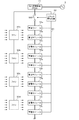
- FIG. 3 is a diagram illustrating a circuit configuration example of each power storage module 10 in FIGS. 1 and 2.
- the power storage module 10 includes a power storage unit 11, a temperature sensor T1, a shunt resistor Rs, and a module management device 12.
- Power storage unit 11 includes a plurality of cells S1-1n connected in series.
- As the cell a lithium ion battery cell, a nickel metal hydride battery cell, an electric double layer capacitor cell, a lithium ion capacitor cell, or the like can be used.
- a lithium ion battery cell nominal voltage: 3.6-3.7 V
- the power storage unit 11 is not limited to an example including a plurality of cells connected in series, and may include a plurality of cells connected in series and parallel.
- a shunt resistor Rs is connected in series with the plurality of cells S1-Sn.
- the shunt resistor Rs functions as a current detection element.
- a Hall element may be used instead of the shunt resistor Rs.
- a temperature sensor T1 for detecting the temperature of the plurality of cells S1-Sn is installed in the vicinity of the plurality of cells S1-Sn.
- a thermistor can be used as the temperature sensor T1.
- a plurality (for example, 3 to 5) of temperature sensors T1 may be installed in one power storage module 10.
- the module management device 12 includes a voltage detection unit 12a, a temperature detection unit 12b, a current detection unit 12c, a control unit 12d, a communication unit 12e, and a storage unit 12f.
- the voltage detector 12a detects each voltage of the plurality of cells S1-Sn and outputs it to the controller 12d.
- the temperature detector 12b estimates the temperature of the plurality of cells S1-Sn based on the output value of the temperature sensor T1, and outputs the estimated temperature to the controller 12d.
- the average of the output values of the plurality of temperature sensors T1 is calculated to estimate the temperatures of the plurality of cells S1-Sn.
- the current detection unit 12c includes an error amplifier connected to both ends of the shunt resistor Rs, and the error amplifier detects a voltage across the shunt resistor Rs.
- the current detection unit 12c detects the current flowing through the power storage unit 11 based on the voltage at both ends, and outputs the current to the control unit 12d.
- the control unit 12d manages the power storage unit 11 based on the voltages, currents, and temperatures of the plurality of cells S1-Sn detected by the voltage detection unit 12a, the current detection unit 12c, and the temperature detection unit 12b. For example, SOC (State Of Of Charge) management, equalization control, etc. of a plurality of cells S1-Sn are executed.
- SOC State Of Of Charge
- the configuration of the control unit 12d can be realized by cooperation of hardware resources and software resources, or only by hardware resources.
- a hardware resource a microcomputer, DSP, FPGA, or other LSI can be used.
- Firmware and other programs can be used as software resources.
- the storage unit 12f can be realized by a ROM and a RAM.
- the control unit 12d estimates the SOC of the cells S1-Sn.
- the SOC can be estimated by, for example, an OCV (Open Circuit Voltage) method and / or a current integration method.
- OCV Open Circuit Voltage
- the SOC of each cell S1-Sn can be estimated by detecting the voltage across each cell S1-Sn in a state where no current flows through the cell S1-Sn. While the current flows through the cells S1-Sn, the increase / decrease in the SOC can be estimated by the current integration method.
- the storage unit 12f stores various programs, data, reference tables, and the like.
- the communication unit 12e executes predetermined communication control processing (for example, communication control processing compliant with standards such as TCP / IP and RS-485), and the other power storage module 10 and / or system management device via the communication line 40 22 to communicate.
- predetermined communication control processing for example, communication control processing compliant with standards such as TCP / IP and RS-485
- the other power storage module 10 and / or system management device via the communication line 40 22 to communicate.
- a metal cable or an optical fiber cable may be used for the communication line 40.
- the system management device 22 controls the switch SW1 based on the voltage, current, temperature, or SOC information acquired from the plurality of power storage modules 10a-10j. Further, the system management device 22 controls the plurality of fans 30a-30d based on the temperatures acquired from the plurality of power storage modules 10a-10j. The system management device 22 drives the plurality of fans 30a to 30d when the acquired average value of temperatures exceeds a set value (for example, 28 ° C.), and the plurality of fans 30a when the average value is equal to or less than the set value. -30d is stopped. When only the temperature of a specific power storage module 10 exceeds the set value, only one or two fans 30 adjacent to the power storage module 10 may be operated.
- a set value for example, 28 ° C.
- the internal resistance of the lithium ion battery cell increases as the environmental temperature is lower. Therefore, when protecting the battery or predicting the life, it is necessary to consider the outside air temperature outside the housing of the power storage module 10.
- the withstand voltage and allowable current design of the power storage module 10 and the power conversion device 21 are set based on a certain environmental temperature range (for example, 18 ° C.-28 ° C.), and in a high temperature or low temperature environment outside the temperature range. When used for a long time, malfunction may occur. Further, when used in a high temperature environment, the actual capacity is reduced as compared with the battery capacity of the specification sheet. The battery manufacturer needs to know whether or not the power storage system 1 is being used at an appropriate environmental temperature by the user in order to guarantee the operation on the assumption that the battery is used at an appropriate environmental temperature.
- the power storage module 10 that performs continuous operation such as FR also needs to estimate the outside air temperature.
- the control unit 12d detects the change amount ⁇ T_fanon of the detected temperature per predetermined period detected when the fans 30a-30d are operating and the predetermined period detected when the fans 30a-30d are stopped.
- the outside air temperature T_o outside the housing of the power storage module 10 is estimated based on the detected temperature change amount ⁇ T_fanoff.
- the predetermined period is set to 1 hour, 2 hours, 4 hours, 6 hours, or the like.
- the fans 30a to 30d are devices that generate an air flow by changing the air flow, and do not change the air temperature itself. Therefore, the temperature of the air blown to the power storage module 10 is basically the same as the temperature of the intake air, and the cooling effect of the power storage module 10 by the fans 30a-30d depends on the environmental temperature. In other words, the environmental temperature can be estimated by calculating back from the cooling effect of the power storage module 10 by the fans 30a-30d.
- the controller 12d estimates the outside air temperature T_o based on the following function (Equation 1).
- T_o f ( ⁇ T_fanon, ⁇ T_fanoff) (Equation 1)
- control unit 12d estimates the outside air temperature T_o with reference to a table having the detected temperature change amount ⁇ T_fanon and the detected temperature change amount ⁇ T_fanoff as input variables and the outside air temperature T_o as output variables. To do.
- FIG. 4A is a diagram illustrating a first example of the reference table 12fa for estimating the outside air temperature T_o.
- the designer generates the reference table 12fa based on experiments and simulations. For example, when the environmental temperature is set to 25 ° C. and the fan 30a-30d is operated, the amount of change in temperature detected by the temperature sensor T1 generated in one hour, and the fan 30a-30d stopped in one hour The amount of change in temperature detected by the generated temperature sensor T1 is measured and recorded.
- the reference table 12fa is completed by executing the process at all environmental temperatures assuming this.
- the charge / discharge current can be added to the input variable.
- the control unit 12d detects the change amount ⁇ T_fanon of the detected temperature per predetermined period detected when the fans 30a-30d are operated, and the change amount of the detected temperature per predetermined period detected when the fans 30a-30d are stopped. Based on ⁇ T_fanoff and the current I flowing through the power storage unit 11, the outside air temperature T_o outside the housing of the power storage module 10 is estimated.
- the controller 12d estimates the outside air temperature T_o based on the following function (Equation 2).
- T_o f ( ⁇ T_fanon, ⁇ T_fanoff, I) (Expression 2)
- control unit 12d refers to a table in which the detected temperature change amount ⁇ T_fanon, the detected temperature change amount ⁇ T_fanoff, the charge / discharge current I are input variables, and the outside air temperature T_o is an output variable.
- the outside air temperature T_o is estimated.
- FIG. 4B is a diagram illustrating a second example of the reference table 12fb for estimating the outside air temperature T_o.
- the designer generates the reference table 12fb based on experiments and simulations.
- the designer generates the reference table shown in FIG. 4A for each charge / discharge current.
- a reference table for each current value is generated in increments of 1A.
- the reference table is generated with the charging current as a positive value and the discharging current as a negative value.
- the charge / discharge current charge / discharge rate
- the control unit 12d estimates the outside air temperature T_o outside the housing of the power storage module 10 based on the change amount ⁇ T of the detected temperature per predetermined period and the charge / discharge rate of the current I flowing through the power storage unit 11 during the predetermined period. . In this case, the outside air temperature T_o can be estimated even in the power storage system 1 in which the fan 30 is not installed.
- the controller 12d estimates the outside air temperature T_o based on the function of the following (Equation 3).
- T_o f ( ⁇ T, I) (Formula 3)
- the temperature outside the housing is estimated based on the amount of change in temperature detected by the temperature sensor T1 installed in the housing, so that the external temperature of the power storage system is The sensor can be obtained without installing it outside. Since there is no need to install a temperature sensor outside, the cost can be reduced. Further, since the temperature sensor is not broken by a physical impact from the outside, the reliability is improved.
- the present invention can also be applied to a configuration in which the power storage module 10 is cooled by liquid cooling.
- the circulation refrigerant for example, water
- the environmental temperature can be estimated backward from the cooling effect of the power storage module 10 by liquid cooling, as in the above-described embodiment.
- the example in which the power storage system 1 includes the plurality of power storage modules 10a to 10j connected in series has been described.
- the number of the power storage modules 10 may be one.
- the system management device 22 is not necessary, and the control unit 12d directly controls the fan 30.
- the control unit 12d estimates the outside air temperature T_o based on the following function (Equation 4).
- T_o f ( ⁇ T_fanon, ⁇ T_fanoff, R) (Formula 4)
- two or more of charge / discharge current I, internal resistance R, SOC, and SOH may be input variables. As the number of input variables increases, the size of the reference table increases, but the estimation accuracy of the outside air temperature T_o can be improved.
- the control unit (12d) includes a change amount of the detected temperature per predetermined period detected when the cooling unit (30) is operating and a predetermined period detected when the cooling unit (30) is stopped.
- the power storage device (10) according to item 1 wherein the outside air temperature is estimated with reference to a table (12fa) in which the change amount of the detected temperature per unit is an input variable and the outside air temperature is an output variable . According to this, the outside air temperature can be easily estimated by referring to the table.
- the control unit (12d) includes a change amount of the detected temperature per predetermined period detected when the cooling unit (30) is operating and a predetermined period detected when the cooling unit (30) is stopped.
- the power storage device (10) according to item 1 wherein an outside air temperature outside the housing is estimated based on a change amount of the detected temperature per round and a current flowing through the power storage unit (11). According to this, the estimation accuracy of the outside air temperature can be improved.
- the control unit (12d) includes a change amount of the detected temperature per predetermined period detected when the cooling unit (30) is operating, and a predetermined period detected when the cooling unit (30) is stopped.
- the power storage device (10) according to item 1 wherein an outside air temperature outside the housing is estimated based on a change amount of the detected temperature and an internal resistance of the power storage unit (11). According to this, the estimation accuracy of the outside air temperature can be improved.
- the cooling unit (30) is a fan (30) installed outside the casing. According to this, the outside air temperature can be inversely estimated from the cooling effect of the fan (30) that sucks outside air and exhausts it toward the power storage unit (11).
- 1 power storage system 1f rack frame, 1p fan mounting plate, 2 systems, 10 power storage module, 11 power storage unit, 12 module management device, 12a voltage detection unit, 12b temperature detection unit, 12c current detection unit, 12d control unit, 12e communication Unit, 12f storage unit, S1-Sn cell, Rs shunt resistor, T1 temperature sensor, SW1 switch, 20 circuit device, 21 power conversion device, 22 system management device, 30 fan, 40 communication line.
Landscapes
- Engineering & Computer Science (AREA)
- Manufacturing & Machinery (AREA)
- Chemical & Material Sciences (AREA)
- Chemical Kinetics & Catalysis (AREA)
- Electrochemistry (AREA)
- General Chemical & Material Sciences (AREA)
- Secondary Cells (AREA)
- Automation & Control Theory (AREA)
Abstract
Selon la présente invention, une unité de détection de température (T1, 12b) détecte la température d'une unité de stockage d'électricité (11) qui est installée à l'intérieur d'un boîtier. Une unité de commande (12d) estime la température de l'extérieur du boîtier sur la base de la température de détection de l'unité de stockage d'électricité (11) détectée par l'unité de détection de température (T1, 12b). L'unité de commande (12d) estime la température de l'air à l'extérieur du boîtier sur la base d'une quantité de changement de la température de détection détectée par période de temps prescrite dans un état dans lequel une unité de refroidissement (30) est actionnée et d'une quantité de changement de la température de détection détectée par période de temps prescrite dans un état dans lequel l'unité de refroidissement (30) est désactivée.
Priority Applications (2)
| Application Number | Priority Date | Filing Date | Title |
|---|---|---|---|
| JP2018520773A JP6872706B2 (ja) | 2016-06-02 | 2017-05-16 | 蓄電装置、及び管理装置 |
| US16/097,681 US11081744B2 (en) | 2016-06-02 | 2017-05-16 | Electricity storage device and management device |
Applications Claiming Priority (2)
| Application Number | Priority Date | Filing Date | Title |
|---|---|---|---|
| JP2016-111262 | 2016-06-02 | ||
| JP2016111262 | 2016-06-02 |
Publications (1)
| Publication Number | Publication Date |
|---|---|
| WO2017208805A1 true WO2017208805A1 (fr) | 2017-12-07 |
Family
ID=60479402
Family Applications (1)
| Application Number | Title | Priority Date | Filing Date |
|---|---|---|---|
| PCT/JP2017/018313 Ceased WO2017208805A1 (fr) | 2016-06-02 | 2017-05-16 | Dispositif de stockage et dispositif de gestion d'électricité |
Country Status (3)
| Country | Link |
|---|---|
| US (1) | US11081744B2 (fr) |
| JP (1) | JP6872706B2 (fr) |
| WO (1) | WO2017208805A1 (fr) |
Cited By (1)
| Publication number | Priority date | Publication date | Assignee | Title |
|---|---|---|---|---|
| JP2023056076A (ja) * | 2021-10-07 | 2023-04-19 | 本田技研工業株式会社 | 電力装置及びその制御方法 |
Families Citing this family (1)
| Publication number | Priority date | Publication date | Assignee | Title |
|---|---|---|---|---|
| KR20230029323A (ko) * | 2021-08-24 | 2023-03-03 | 삼성전자주식회사 | 스토리지 패키지, 스토리지 장치 및 스토리지 장치의 구동 방법 |
Citations (6)
| Publication number | Priority date | Publication date | Assignee | Title |
|---|---|---|---|---|
| JPH09159541A (ja) * | 1995-12-12 | 1997-06-20 | Oki Electric Ind Co Ltd | 温度検出方法および温度検出機能を有するプリンタ装置 |
| JPH09224333A (ja) * | 1996-02-19 | 1997-08-26 | Nec Eng Ltd | バックアップ用蓄電池の充電装置 |
| JP2002108483A (ja) * | 2000-10-02 | 2002-04-10 | Hitachi Ltd | 情報処理装置の制御方法および情報処理装置 |
| JP2009265280A (ja) * | 2008-04-23 | 2009-11-12 | Canon Inc | 画像形成装置及びその制御方法 |
| JP2012191770A (ja) * | 2011-03-11 | 2012-10-04 | Yamaha Corp | 電気機器の電力管理装置 |
| JP2015073392A (ja) * | 2013-10-03 | 2015-04-16 | 株式会社日立産機システム | 給水装置、およびそれに用いるポンプを駆動する同期電動機を制御するインバータ |
Family Cites Families (4)
| Publication number | Priority date | Publication date | Assignee | Title |
|---|---|---|---|---|
| JP2013200979A (ja) | 2012-03-23 | 2013-10-03 | Sanyo Electric Co Ltd | 制御装置 |
| WO2014110524A1 (fr) * | 2013-01-14 | 2014-07-17 | Gentherm Incorporated | Gestion thermique à base thermoélectrique de dispositifs électriques |
| JP2014171002A (ja) | 2013-03-01 | 2014-09-18 | Nikon Corp | 撮像装置 |
| JP2014187807A (ja) * | 2013-03-22 | 2014-10-02 | Toyota Motor Corp | 蓄電システム |
-
2017
- 2017-05-16 US US16/097,681 patent/US11081744B2/en active Active
- 2017-05-16 WO PCT/JP2017/018313 patent/WO2017208805A1/fr not_active Ceased
- 2017-05-16 JP JP2018520773A patent/JP6872706B2/ja active Active
Patent Citations (6)
| Publication number | Priority date | Publication date | Assignee | Title |
|---|---|---|---|---|
| JPH09159541A (ja) * | 1995-12-12 | 1997-06-20 | Oki Electric Ind Co Ltd | 温度検出方法および温度検出機能を有するプリンタ装置 |
| JPH09224333A (ja) * | 1996-02-19 | 1997-08-26 | Nec Eng Ltd | バックアップ用蓄電池の充電装置 |
| JP2002108483A (ja) * | 2000-10-02 | 2002-04-10 | Hitachi Ltd | 情報処理装置の制御方法および情報処理装置 |
| JP2009265280A (ja) * | 2008-04-23 | 2009-11-12 | Canon Inc | 画像形成装置及びその制御方法 |
| JP2012191770A (ja) * | 2011-03-11 | 2012-10-04 | Yamaha Corp | 電気機器の電力管理装置 |
| JP2015073392A (ja) * | 2013-10-03 | 2015-04-16 | 株式会社日立産機システム | 給水装置、およびそれに用いるポンプを駆動する同期電動機を制御するインバータ |
Cited By (2)
| Publication number | Priority date | Publication date | Assignee | Title |
|---|---|---|---|---|
| JP2023056076A (ja) * | 2021-10-07 | 2023-04-19 | 本田技研工業株式会社 | 電力装置及びその制御方法 |
| JP7663469B2 (ja) | 2021-10-07 | 2025-04-16 | 本田技研工業株式会社 | 電力装置及びその制御方法 |
Also Published As
| Publication number | Publication date |
|---|---|
| US20200365957A1 (en) | 2020-11-19 |
| JPWO2017208805A1 (ja) | 2019-03-28 |
| JP6872706B2 (ja) | 2021-05-19 |
| US11081744B2 (en) | 2021-08-03 |
Similar Documents
| Publication | Publication Date | Title |
|---|---|---|
| JP6564647B2 (ja) | 電池の劣化状態推定装置及び、その劣化状態推定方法 | |
| US20190109306A1 (en) | Power storage system and management device | |
| JP5687340B2 (ja) | 電池制御装置、電池システム | |
| JP6162884B2 (ja) | 電池パック、制御回路および制御方法 | |
| JPWO2019130774A1 (ja) | 電池管理装置、電池システム、及び車両用電源システム | |
| CN102792513A (zh) | 具有平均温度及热点回授之热感测器装置 | |
| JP6168962B2 (ja) | 異常判定装置、充放電情報提示装置、二次電池モジュール、異常判定方法、及びプログラム | |
| JPWO2019039120A1 (ja) | 蓄電システム、及び管理装置 | |
| JPWO2019163301A1 (ja) | 管理装置、蓄電システム | |
| US11978913B2 (en) | Battery power management for a battery backup unit (BBU) shelf | |
| JP2017156272A (ja) | 電池の劣化状態推定装置及び、その劣化状態推定方法 | |
| CN107004514B (zh) | 用于均衡能量存储器系统的方法 | |
| JP2017220293A (ja) | 電池の充放電曲線推定装置及び、その充放電曲線推定方法 | |
| JP6773889B2 (ja) | 蓄電池の劣化予測装置、蓄電池システム、方法及びプログラム | |
| JP6872706B2 (ja) | 蓄電装置、及び管理装置 | |
| JP2013005663A (ja) | 電池パック入出力制御装置 | |
| EP4466774B1 (fr) | Commande de décharge de batterie intelligente pour supporter des conditions extrêmes de l'environnement | |
| CN114628806B (zh) | 用于室外安装的计算设备的多电池单体架构 | |
| KR102684713B1 (ko) | 배터리 관리 시스템 및 이의 제어방법 | |
| CN113764756B (zh) | 应用于极端工况环境的储能电源 | |
| CN112639496B (zh) | 用于确定与第二电蓄能单元复合的第一电蓄能单元的周围环境温度的方法以及相对应的设备、计算机程序和机器可读存储介质 | |
| JP7124596B2 (ja) | 電池温度センサの異常検出装置 | |
| KR20220129386A (ko) | 배터리 관리 시스템, 배터리 팩, 전기 차량 및 배터리 관리 방법 | |
| US12451720B2 (en) | Hybrid capacitor energy storage | |
| WO2026074313A1 (fr) | Système de stockage et de gestion d'énergie |
Legal Events
| Date | Code | Title | Description |
|---|---|---|---|
| WWE | Wipo information: entry into national phase |
Ref document number: 2018520773 Country of ref document: JP |
|
| NENP | Non-entry into the national phase |
Ref country code: DE |
|
| 121 | Ep: the epo has been informed by wipo that ep was designated in this application |
Ref document number: 17806363 Country of ref document: EP Kind code of ref document: A1 |
|
| 122 | Ep: pct application non-entry in european phase |
Ref document number: 17806363 Country of ref document: EP Kind code of ref document: A1 |