WO2017208890A1 - Dispositif de commande, procédé de commande et programme informatique - Google Patents
Dispositif de commande, procédé de commande et programme informatique Download PDFInfo
- Publication number
- WO2017208890A1 WO2017208890A1 PCT/JP2017/019054 JP2017019054W WO2017208890A1 WO 2017208890 A1 WO2017208890 A1 WO 2017208890A1 JP 2017019054 W JP2017019054 W JP 2017019054W WO 2017208890 A1 WO2017208890 A1 WO 2017208890A1
- Authority
- WO
- WIPO (PCT)
- Prior art keywords
- vehicle
- control
- control device
- program
- usage pattern
- Prior art date
- Legal status (The legal status is an assumption and is not a legal conclusion. Google has not performed a legal analysis and makes no representation as to the accuracy of the status listed.)
- Ceased
Links
Images

Classifications
-
- G—PHYSICS
- G06—COMPUTING OR CALCULATING; COUNTING
- G06F—ELECTRIC DIGITAL DATA PROCESSING
- G06F8/00—Arrangements for software engineering
- G06F8/60—Software deployment
- G06F8/65—Updates
-
- B—PERFORMING OPERATIONS; TRANSPORTING
- B60—VEHICLES IN GENERAL
- B60R—VEHICLES, VEHICLE FITTINGS, OR VEHICLE PARTS, NOT OTHERWISE PROVIDED FOR
- B60R16/00—Electric or fluid circuits specially adapted for vehicles and not otherwise provided for; Arrangement of elements of electric or fluid circuits specially adapted for vehicles and not otherwise provided for
- B60R16/02—Electric or fluid circuits specially adapted for vehicles and not otherwise provided for; Arrangement of elements of electric or fluid circuits specially adapted for vehicles and not otherwise provided for electric constitutive elements
- B60R16/023—Electric or fluid circuits specially adapted for vehicles and not otherwise provided for; Arrangement of elements of electric or fluid circuits specially adapted for vehicles and not otherwise provided for electric constitutive elements for transmission of signals between vehicle parts or subsystems
-
- B—PERFORMING OPERATIONS; TRANSPORTING
- B60—VEHICLES IN GENERAL
- B60W—CONJOINT CONTROL OF VEHICLE SUB-UNITS OF DIFFERENT TYPE OR DIFFERENT FUNCTION; CONTROL SYSTEMS SPECIALLY ADAPTED FOR HYBRID VEHICLES; ROAD VEHICLE DRIVE CONTROL SYSTEMS FOR PURPOSES NOT RELATED TO THE CONTROL OF A PARTICULAR SUB-UNIT
- B60W50/00—Details of control systems for road vehicle drive control not related to the control of a particular sub-unit, e.g. process diagnostic or vehicle driver interfaces
- B60W50/0098—Details of control systems ensuring comfort, safety or stability not otherwise provided for
-
- G—PHYSICS
- G05—CONTROLLING; REGULATING
- G05B—CONTROL OR REGULATING SYSTEMS IN GENERAL; FUNCTIONAL ELEMENTS OF SUCH SYSTEMS; MONITORING OR TESTING ARRANGEMENTS FOR SUCH SYSTEMS OR ELEMENTS
- G05B19/00—Program-control systems
- G05B19/02—Program-control systems electric
- G05B19/04—Program control other than numerical control, i.e. in sequence controllers or logic controllers
- G05B19/042—Program control other than numerical control, i.e. in sequence controllers or logic controllers using digital processors
- G05B19/0426—Programming the control sequence
-
- G—PHYSICS
- G06—COMPUTING OR CALCULATING; COUNTING
- G06F—ELECTRIC DIGITAL DATA PROCESSING
- G06F11/00—Error detection; Error correction; Monitoring
-
- H—ELECTRICITY
- H04—ELECTRIC COMMUNICATION TECHNIQUE
- H04L—TRANSMISSION OF DIGITAL INFORMATION, e.g. TELEGRAPHIC COMMUNICATION
- H04L67/00—Network arrangements or protocols for supporting network services or applications
- H04L67/34—Network arrangements or protocols for supporting network services or applications involving the movement of software or configuration parameters
-
- B—PERFORMING OPERATIONS; TRANSPORTING
- B60—VEHICLES IN GENERAL
- B60W—CONJOINT CONTROL OF VEHICLE SUB-UNITS OF DIFFERENT TYPE OR DIFFERENT FUNCTION; CONTROL SYSTEMS SPECIALLY ADAPTED FOR HYBRID VEHICLES; ROAD VEHICLE DRIVE CONTROL SYSTEMS FOR PURPOSES NOT RELATED TO THE CONTROL OF A PARTICULAR SUB-UNIT
- B60W50/00—Details of control systems for road vehicle drive control not related to the control of a particular sub-unit, e.g. process diagnostic or vehicle driver interfaces
- B60W2050/0062—Adapting control system settings
- B60W2050/0075—Automatic parameter input, automatic initialising or calibrating means
-
- G—PHYSICS
- G05—CONTROLLING; REGULATING
- G05B—CONTROL OR REGULATING SYSTEMS IN GENERAL; FUNCTIONAL ELEMENTS OF SUCH SYSTEMS; MONITORING OR TESTING ARRANGEMENTS FOR SUCH SYSTEMS OR ELEMENTS
- G05B2219/00—Program-control systems
- G05B2219/20—Pc systems
- G05B2219/23—Pc programming
- G05B2219/23328—Modification program
Definitions
- the present invention relates to a control device, a control method, and a computer program.
- This application claims priority based on Japanese Application No. 2016-110613 filed on June 2, 2016 and Japanese Application No. 2016-210148 filed on October 27, 2016, and is described in the aforementioned Japanese application. All described contents are used.
- ECUs Electronic Control Units
- the types of ECUs include, for example, those related to the traveling system that controls the engine, brakes, EPS (Electric Power Steering), etc. for the operation of the accelerator, brake, and steering wheel, the interior lighting and the head according to the switch operation by the passenger
- body-type ECUs that control the turning on / off of lights and the sounding of alarm devices
- meter-type ECUs that control the operation of meters arranged near the driver's seat.
- the ECU is configured by an arithmetic processing device such as a microcomputer, and the control of the in-vehicle device is realized by reading and executing a control program stored in a ROM (Read Only Memory).
- the control program of the ECU may differ depending on the destination and grade of the vehicle, and it is necessary to rewrite the old version control program to the new version control program in response to the upgrade of the control program.
- Patent Document 1 when it is necessary to update an ECU control program, a travel route in which the ECU does not execute control processing is set, and when the vehicle is traveling along this travel route, the ECU control processing is performed.
- a vehicle control device that determines that the ECU does not perform the program update of the ECU. According to the vehicle control device of Patent Document 1, since the program update is executed when the vehicle travels without ECU control processing, the program update can be executed early.
- An apparatus is an apparatus that controls update of a control program of an in-vehicle control device that controls a target device mounted on a vehicle, and the control function of the in-vehicle control device during vehicle travel
- An acquisition unit for acquiring the usage pattern, and a control unit for determining whether or not the control program for the in-vehicle control device can be updated based on the acquired usage pattern.
- a method is a method of controlling update of a control program of an in-vehicle control device that controls a target device mounted on a vehicle, and the control function of the in-vehicle control device during vehicle travel And a step of determining whether or not the control program can be updated based on the acquired usage pattern.
- a computer program is a computer program for causing a computer to function as a control device that controls updating of a control program of an in-vehicle control device that controls a target device mounted on a vehicle.
- the computer functions as an acquisition unit that acquires a usage pattern of a control function of the in-vehicle control device when the vehicle is traveling, and a control unit that determines whether the control program can be updated based on the acquired usage pattern.
- FIG. 1 is an overall configuration diagram of a program update system according to an embodiment.
- FIG. 2 is a block diagram showing the internal configuration of the gateway.
- FIG. 3 is a block diagram showing an internal configuration of the ECU.
- FIG. 4 is a block diagram showing the internal configuration of the management server.
- FIG. 5 is a sequence diagram illustrating an example of updating the control program for the target ECU.
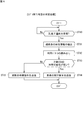
- FIG. 6 is a flowchart illustrating an example of the repro execution determination process.
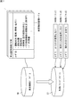
- FIG. 7 is an explanatory diagram illustrating an example of usage pattern generation processing.
- a travel route that satisfies conditions (such as vehicle travel conditions, road conditions, and surrounding environmental conditions) in which the control function of the ECU to be updated does not operate is set.
- Program update is performed while driving. Accordingly, since the program is updated during traveling, a traveling route that is not assumed by the user of the vehicle may be set, which may cause the user to feel bothered.
- the present disclosure provides a control device and the like that can appropriately determine whether or not the control program can be updated while the vehicle is traveling without setting a travel route in which the vehicle control device does not execute the control function. This is one of the purposes.
- the control device of the present embodiment is a device that controls updating of a control program of an in-vehicle control device that controls a target device mounted on a vehicle, and uses a control function of the in-vehicle control device when the vehicle travels.
- An acquisition unit that acquires a pattern, and a control unit that determines whether the control program can be updated for the in-vehicle control device based on the acquired usage pattern.
- the acquisition unit acquires the usage pattern of the control function of the in-vehicle control device during vehicle travel, and the control unit controls the in-vehicle control device based on the acquired usage pattern. Therefore, it is possible to appropriately determine whether or not the control program can be updated while the vehicle is traveling without setting a travel route in which the in-vehicle control device does not execute the control function.
- control unit determines the possibility of use of the control function of the in-vehicle control device during vehicle travel based on the acquired usage pattern, In response, whether or not the control program can be updated is determined.
- control unit determines that the control program can be updated when the availability is equal to or less than a predetermined threshold. Therefore, it is possible to prevent the user from feeling inconvenient by being recommended to update the control program of the in-vehicle control device corresponding to the control function while the user is using a certain control function. .
- the usage pattern includes a usage pattern set for each identification information of a user who can drive the vehicle.
- the control unit can execute whether or not the control program of the in-vehicle control device can be updated based on the usage pattern for each user. Therefore, the update process by the in-vehicle control device can be permitted at an appropriate timing that the user does not feel inconvenient.
- the identification information of the user includes identification information when the vehicle is in automatic driving. In this way, it is possible to determine whether or not the control program for the in-vehicle control device can be updated based on the usage pattern even for a vehicle that is operating automatically.
- control apparatus further includes a generation unit that generates the usage pattern based on accumulation of operation status of the control function.
- the usage pattern is generated based on the accumulation of the operation status of the control function, so that the accuracy of the usage pattern can be improved. Therefore, it is possible to appropriately determine whether or not the control program can be updated while the vehicle is running.
- the control method of the present embodiment relates to a control method executed by the control device according to any one of (1) to (6) described above. Therefore, the control method of the present embodiment has the same effects as the control device described in any one of the above (1) to (6).
- the computer program of the present embodiment relates to a computer program for causing a computer to function as the control device according to any one of (1) to (6) described above. Therefore, the computer program of the present embodiment has the same operational effects as the control device described in any of (1) to (6) above.
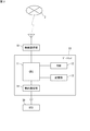
- FIG. 1 is an overall configuration diagram of a program update system according to an embodiment.
- the program update system of this embodiment includes a vehicle 1, a management server 5, and a DL (download) server 6 that can communicate via a wide area communication network 2.
- the management server 5 and the DL server 6 are operated by, for example, a car manufacturer of the vehicle 1 and can communicate with a large number of vehicles 1 owned by a user who is registered as a member in advance.
- Each vehicle 1 is equipped with a gateway 10, a wireless communication unit 15, a plurality of ECUs 30, and various in-vehicle devices (not shown) controlled by the respective ECUs 30.
- Each vehicle 1 has a communication group of a plurality of ECUs 30 that are bus-connected to a common in-vehicle communication line, and the gateway 10 relays communication between the communication groups. Therefore, a plurality of in-vehicle communication lines are connected to the gateway 10.
- the wireless communication unit 15 is communicably connected to a wide area communication network 2 such as a mobile phone network, and is connected to the gateway 10 via an in-vehicle communication line.
- the gateway 10 transmits the information received by the wireless communication unit 15 from the vehicle external devices such as the management server 5 and the DL server 6 to the ECU 30 through the wide area communication network 2.
- the gateway 10 transmits information acquired from the ECU 30 to the wireless communication unit 15, and the wireless communication unit 15 transmits the information to an external device such as the management server 5.
- Examples of the wireless communication unit 15 mounted on the vehicle 1 include devices such as a mobile phone, a smartphone, a tablet terminal, and a notebook PC (Personal Computer) owned by the user.
- the gateway 10 communicates with an external device via the wireless communication unit 15 is illustrated, but when the gateway 10 has a wireless communication function, the gateway 10 itself is the management server 5 or the like It is good also as a structure which performs radio
- the management server 5 and the DL server 6 are configured as separate servers, but these servers 5 and 6 may be configured as one server device.
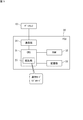
- FIG. 2 is a block diagram showing the internal configuration of the gateway 10.
- the gateway 10 includes a CPU (Central Processing Unit) 11, a RAM (Random Access Memory) 12, a storage unit 13, an in-vehicle communication unit 14, and the like.
- the gateway 10 is connected to the wireless communication unit 15 via the in-vehicle communication line, but these may be configured by one device.
- the CPU 11 causes the gateway 10 to function as a relay device for various information by reading one or more programs stored in the storage unit 13 into the RAM 12 and executing them.
- the CPU 11 can execute a plurality of programs in parallel, for example, by switching and executing a plurality of programs in a time division manner.
- the CPU 11 includes one or a plurality of large scale integrated circuits (LSIs).
- LSIs large scale integrated circuits
- the RAM 12 is composed of a memory element such as SRAM (Static RAM) or DRAM (Dynamic RAM), and temporarily stores programs executed by the CPU 11, data necessary for execution, and the like.
- the computer program executed by the CPU 11 can be transferred while being recorded on a known recording medium such as a CD-ROM or DVD-ROM, or can be transferred by information transmission (downloading) from a computer device such as a server computer. You can also. The same applies to a computer program executed by a CPU 31 (see FIG. 3) of an ECU 30 described later and a computer program executed by a CPU 51 (see FIG. 4) of a management server 5 described later.
- the storage unit 13 includes a nonvolatile memory element such as a flash memory or an EEPROM (Electrically Erasable Programmable Read Only Memory).
- the storage unit 13 has a storage area for storing programs executed by the CPU 11, data necessary for execution, and the like.
- the storage unit 13 also stores an update program for each ECU 30 received from the DL server 6.
- a plurality of ECUs 30 are connected to the in-vehicle communication unit 14 via an in-vehicle communication line disposed in the vehicle 1.
- the in-vehicle communication unit 14 is, for example, CAN (Controller Area Network), CANFD (CAN with Flexible Data Rate), LIN (Local Interconnect Network), Ethernet (registered trademark), or MOST (Media Oriented Systems Transport: MOST is a registered trademark). Communication with the ECU 30 is performed according to the standard.
- the in-vehicle communication unit 14 transmits the information given from the CPU 11 to the target ECU 30 and gives the information received from the ECU 30 to the CPU 11.
- the in-vehicle communication unit 14 may communicate according to other communication standards used for the in-vehicle network as well as the above communication standards.
- the wireless communication unit 15 includes a wireless communication device including an antenna and a communication circuit that performs transmission / reception of a wireless signal from the antenna.
- the wireless communication unit 15 can communicate with an external device by being connected to a wide area communication network 2 such as a mobile phone network.
- the wireless communication unit 15 transmits information given from the CPU 11 to an external device such as the management server 5 via the wide area communication network 2 formed by a base station (not shown), and receives information received from the external device to the CPU 11. give.
- a wired communication unit that functions as a relay device in the vehicle 1 may be employed.
- the wired communication unit has a connector to which a communication cable conforming to a standard such as USB (Universal Serial Bus) or RS232C is connected, and performs wired communication with another communication apparatus connected via the communication cable.
- a communication cable conforming to a standard such as USB (Universal Serial Bus) or RS232C is connected
- RS232C Universal Serial Bus
- the outside of the vehicle depends on the communication path of the outside device ⁇ another communication device ⁇ the wired communication unit ⁇ the gateway 10.
- the apparatus and the gateway 10 can communicate with each other.
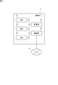
- FIG. 3 is a block diagram showing an internal configuration of the ECU 30.
- the ECU 30 includes a CPU 31, a RAM 32, a storage unit 33, a communication unit 34, and the like.
- the ECU 30 is an in-vehicle control device that individually controls target devices mounted on the vehicle 1.
- the types of ECU 30 include, for example, a travel system ECU related to an engine, a brake and a steering function, a body system control ECU such as a headlight and a door lock, and an automatic travel system ECU such as a lane keep assist.
- the CPU 31 controls the operation of the target device that it is in charge of by reading one or more programs stored in advance in the storage unit 33 into the RAM 32 and executing them.
- the CPU 31 includes one or a plurality of large scale integrated circuits (LSIs). In the CPU 31 including a plurality of LSIs, the functions of the CPU 31 are realized by the cooperation of the plurality of LSIs.
- the RAM 32 is composed of a memory element such as SRAM or DRAM, and temporarily stores programs executed by the CPU 31, data necessary for execution, and the like.
- the storage unit 33 is configured by a nonvolatile memory element such as a flash memory or an EEPROM, or a magnetic storage device such as a hard disk.
- the information stored in the storage unit 33 includes, for example, a computer program (hereinafter referred to as “control program”) for causing the CPU 31 to execute information processing for controlling a target device that is a control target in the vehicle.
- the communication unit 34 is connected to the gateway 10 via an in-vehicle communication line disposed in the vehicle 1.
- the communication unit 34 communicates with the gateway 10 according to a standard such as CAN, Ethernet, or MOST.
- the communication unit 34 transmits the information given from the CPU 31 to the gateway 10 and gives the information received from the gateway 10 to the CPU 31.
- the communication unit 34 may communicate according to other communication standards used for the in-vehicle network, in addition to the above communication standards.
- the CPU 31 of the ECU 30 includes an activation unit 35 that switches the control mode by the CPU 31 to either “normal mode” or “reprogramming mode” (hereinafter also referred to as “repro mode”).
- the normal mode is a control mode in which the CPU 31 of the ECU 30 executes an original control on the target device (for example, engine control on the fuel engine, door lock control on the door lock motor, etc.).
- the reprogramming mode is a control mode in which a control program used for controlling the target device is updated. That is, the reprogramming mode is a control mode in which the CPU 31 erases or rewrites the control program in the ROM area of the storage unit 33. Only in this control mode, the CPU 31 can update the control program stored in the ROM area of the storage unit 33 to a new version.
- the starting unit 35 restarts (resets) the ECU 30 once, and executes the verification process on the storage area in which the new version of the control program is written. .
- the activation unit 35 causes the CPU 31 to operate according to the updated control program after the above-described verification processing is completed.
- FIG. 4 is a block diagram showing the internal configuration of the management server 5.
- the management server 5 includes a CPU 51, a ROM 52, a RAM 53, a storage unit 54, a communication unit 55, and the like.
- the CPU 51 reads out one or more programs stored in advance in the ROM 52 to the RAM 53 and executes them, thereby controlling the operation of each hardware and causing the management server 5 to function as an external device that can communicate with the gateway 10.
- the CPU 51 includes one or a plurality of large scale integrated circuits (LSIs). In the CPU 51 including a plurality of LSIs, the functions of the CPU 51 are realized by the cooperation of the plurality of LSIs.
- the RAM 53 is configured by a memory element such as SRAM or DRAM, and temporarily stores programs executed by the CPU 51 and data necessary for execution.
- the storage unit 54 includes a nonvolatile memory element such as a flash memory or an EEPROM, or a magnetic storage device such as a hard disk.
- the communication unit 55 includes a communication device that executes communication processing in accordance with a predetermined communication standard, and is connected to the wide area communication network 2 such as a mobile phone network to execute the communication processing.
- the communication unit 55 transmits the information given from the CPU 51 to the external device via the wide area communication network 2 and gives the information received via the wide area communication network 2 to the CPU 51.
- the information stored in the storage unit 54 includes a service management table (not shown) for managing personal information of a registered member user, version information of a control program executed by the ECU 30 mounted on the vehicle 1, and the like. Is included.
- the service management table is a reference that summarizes the vehicle identification number (VIN) of the vehicle 1 owned by the registered member, the type of the ECU 30 for each vehicle identification number, and the history of version information of the control program executed by each ECU 30. It consists of a table.
- the DL server 6 stores an update program for each version of the control program executed by the ECU 30 for all types of ECUs 30.
- the update program held by the DL server 6 may be the latest version of the control program to be installed in the ECU 30, or a difference program (hereinafter referred to as a difference program) between the old version control program and the new version control program.
- the update program may be described as “ ⁇ ”).
- the gateway 10 of the vehicle 1 transmits a communication packet including version information of the control program being used by the ECU 30 mounted on the host vehicle and the vehicle identification number of the host vehicle to the management server 5 every predetermined time. .
- the CPU 51 of the management server 5 determines whether or not the version information of the control program included in the communication packet received from the gateway 10 is the latest version with reference to the service management table.
- the CPU 51 transmits a communication packet including the URL of the DL server 6 that is the storage destination of the update program to the gateway 10.
- the gateway 10 that has received the communication packet transmits a download request including the URL notified from the management server 5 and the type of the ECU 30 to be reprogrammed to the DL server 6.
- the DL server 6 that has received the download request transmits an update program corresponding to the type of the ECU 30 notified from the gateway 10 to the gateway 10 that is the transmission source of the download request.
- the CPU 31 of the gateway 10 that has received the update program transfers the received update program to the ECU 30 and causes the ECU 30 to execute processing for updating the control program to the latest version.
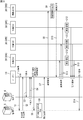
- FIG. 5 is a sequence diagram showing an example of control program update for the target ECUs 30A to 30C, which is executed in the program update system of the present embodiment.
- the “target ECU” refers to the ECU 30 that is a control program update target.
- the “information system ECU” is an ECU 30 that controls information-related target devices such as a car navigation device, a liquid crystal display (display device), and an input device of the device.
- the gateway 10 transmits a communication packet including the version information of the control program of the target ECUs 30A to 30C of the own vehicle, the vehicle identification number (VIN) of the own vehicle, and the like to the management server 5 (step S1). ).
- the management server 5 searches the service management table described above based on the version information and the vehicle identification number included in the received communication packet, and determines the necessity of updating the control program related to the target ECUs 30A to 30C.
- the management server 5 determines that the target ECUs 30A to 30C of the vehicle 1 need to be updated. In this case, the management server 5 sends a download request including the update program storage destination URL (URL of the update program storage folder in the DL server 6) of the target ECUs 30A to 30C to the gateway 10 that is the packet transmission source (step S2). ).
- the update program storage destination URL URL of the update program storage folder in the DL server 6
- the gateway 10 accesses the storage destination URL and transmits a communication packet requesting the update program ⁇ of the target ECUs 30A to 30C to the DL server 6 (step S3).
- the DL server 6 transmits the update program ⁇ to the gateway 10 (Step S4).
- the gateway 10 temporarily stores and saves the update program in the storage unit 13 of its own device, and transmits a download completion notification to the management server 5 (step S5).
- the gateway 10 includes the current vehicle information of the vehicle 1 that is used by the management server 5 for the “repro execution determination process” (step S6) described later in the download completion notification.
- the current vehicle information includes, for example, a user ID, driving status (parking / stopped / running), current position, current time, OD (Origin-Destination) information (including travel route), and remaining battery power. The amount is included.
- the user ID is identification information defined separately from the vehicle identification information so that the driver of the vehicle 1 can be identified.
- User IDs of a plurality of users who drive the same vehicle 1 can be defined using smart key information or the like. For example, when three users (such as the owner of the vehicle 1, its spouse, and their eldest son) share one vehicle 1, the values of three smart key information corresponding to one vehicle identification information (VIN) May be the user ID of each person.
- the management server 5 executes “repro execution determination process” (step S6).
- This determination process is a process of determining whether or not the control program can be updated according to the availability of the control function performed by the target ECUs 30A to 30C.
- the availability of the control functions of the target ECUs 30A to 30C is determined based on the usage pattern stored in advance by the management server 5. Details of the repro execution determination process (FIG. 6) based on the usage pattern will be described later.
- the management server 5 transmits a control program update execution request to the gateway 10 (step S7).
- the gateway 10 that has received the execution request transmits a confirmation request to the information system ECU 30D in order to make the user confirm whether or not the update of the control program using the update program ⁇ is necessary (step S8).
- the information system ECU 30D displays a confirmation screen as to whether execution is necessary or not on a display device such as a liquid crystal display of the car navigation device (step S9).
- a confirmation screen for example, “Do you want to update the control program of the target ECUs 30A to 30C?”, “Can update the control program of the target ECUs 30A to 30C. Run now? Run later?”
- a display that allows the user to select whether or not to perform the update is included.
- an update execution input signal is transmitted to the information system ECU 30D, and the information system ECU 30D transmits an update permission to the gateway 10 (step S10).
- the gateway 10 Upon receiving the update permission, the gateway 10 transmits a control program update request to the target ECUs 30A to 30C (step S11), and transfers the update program ⁇ to the target ECUs 30A to 30C.
- the target ECUs 30A to 30C that have received the update request execute control program update processing (step S12). Specifically, the activation unit 35 of the CPU 31 of the target ECUs 30A to 30C switches its own control mode from the normal mode to the repro mode (see FIG. 3), expands the received update program ⁇ , and controls the old version of the control program By applying to, the control program is rewritten from the old version to the new version.
- the target ECUs 30A to 30C each transmit a notification of completion of the update process of the own machine to the gateway 10 (step S13).
- the gateway 10 transmits to the management server 5 a vehicle identification number of the host vehicle and a completion notification indicating that the update processing of the target ECUs 30A and 30B has been completed (step S14).
- the management server 5 that has received the completion notification updates the contents of the service management table managed by its own device. Specifically, the management server 5 searches for the vehicle identification number included in the completion notification received from the gateway 10, and updates the version information of the control program of the target ECUs 30A to 30C associated with the identification number to the new version. To do.
- FIG. 6 is a flowchart showing an example of repro execution determination processing executed by the CPU 51 of the management server 5. As shown in FIG. 6, the CPU 51 of the management server 5 continuously determines whether or not a downlink completion notification has been received from the gateway 10 (step ST10).
- the CPU 51 that has received the download completion notification extracts the current vehicle information of the vehicle 1 from the completion notification (step ST11), and “uses” the control functions of the target ECUs 30A to 30C from the storage unit 54 of the own device when the vehicle travels. "Pattern” is read (step ST12).
- the usage pattern refers to a usage tendency of the control target of the ECU 30 by the user of the vehicle 1, for example, whether a specific user or all users use the control target of the ECU 30 or not. Means.
- the CPU 51 of the management server 5 determines whether or not the target ECUs 30A to 30C are less likely to be used when the vehicle is traveling based on the current vehicle information of the vehicle 1 and the usage pattern when the vehicle is traveling, which is stored in the own device. It is determined whether or not (step ST13). Specifically, for example, when the availability of the target ECUs 30A to 30C based on the usage pattern is equal to or less than a predetermined threshold (for example, 5%), the CPU 51 determines that the availability is low and exceeds the predetermined threshold. In the case, it is determined that the availability is high.
- a predetermined threshold for example, 5%
- step ST13 When the determination result of step ST13 is affirmative, the CPU 51 transmits an update execution request to the gateway 10 (step ST14). As described above, the gateway 10 that has received the execution request transmits a confirmation request to the information system ECU 30D of the host vehicle (step S8 in FIG. 5). Thereby, the user of the vehicle 1 is notified of whether or not the target ECUs 30A to 30C are to be executed (step S9 in FIG. 5).
- step ST15 the CPU 51 transmits an update standby command to the gateway 10 (step ST15).
- the standby command includes, for example, a communication packet that commands retransmission of a download completion notification after a predetermined time (for example, about 1 hour to 1 day) has elapsed. Therefore, the CPU 51 of the management server 5 executes again the repro-executable determination process (FIG. 6) triggered by the download completion notification received from the gateway 10 after a predetermined time has elapsed.
- control function updated by the target ECU 30 ⁇ / b> A is “auto light” (a function of turning on or off a headlight or the like according to illuminance).
- the usage pattern stored in the management server 5 is “the user 1 has a 1% possibility of using auto light”.
- the CPU 51 of the management server 5 determines that the availability of the target ECU 30A is low (Yes in step ST13).
- An update execution request for the target ECU 30A is transmitted (step ST14).
- the usage pattern stored in the management server 5 is “For User 1, the possibility of using autolight during the daytime (12:00 to 15:00) is 1%, and autolight is used at other times. The possibility of use is 10%. "
- the CPU 51 of the management server 5 determines that the availability of the target ECU 30A is high when the user ID notified from the gateway 10 is “user 1” and the current time is a time zone other than daytime. (No in step ST13), an update standby request for the target ECU 30A is transmitted (step ST15).
- the usage pattern stored in the management server 5 is “For user 1, the possibility of using auto light when passing through the tunnel is 20%, and the possibility of using auto light in other sections is 1%. . "
- the CPU 51 of the management server 5 can use the target ECU 30A. Is determined to be high (No in step ST13), and an update standby request for the target ECU 30A is transmitted (step ST15).
- the usage pattern stored in the management server 5 is “the user 2 has a 1% possibility of using LKA in a predetermined road section on the expressway”.
- the CPU 51 of the management server 5 has a user ID “user 2” included in the download completion notification of the gateway 10 and is expected to travel on a predetermined road section from the current time, current position, and OD information. Is determined that the availability of the target ECU 30B is low (Yes in step ST13), and an update execution request for the target ECU 30B is transmitted (step ST14).
- the usage pattern stored in the management server 5 is “the possibility of using the wiper during traveling on a sunny day is 30% for the user 3”.
- the CPU 51 of the management server 5 determines that the availability of the target ECU 30C is high ( No in step ST13), an update standby request relating to the target ECU 30C is transmitted (step ST15).
- FIG. 7 is an explanatory diagram illustrating an example of usage pattern generation processing executed by the CPU 51 of the management server 5.
- “Use pattern generation processing” refers to the use pattern (use of predetermined ECU control function) from vehicle information acquired from the vehicle 1 and information (weather, road type, etc.) that the management server 5 can acquire from other than the vehicle 1. (Trend) is generated.
- a vehicle information database 56 and a usage pattern database 57 are stored in the storage unit 54 of the management server 5.
- the vehicle information database 56 includes a plurality of “vehicle information management tables”.
- the vehicle information included in this management table is extracted from communication packets received by the management server 5 from the gateway 10 of the vehicle 1 every predetermined time (for example, 1 to 5 seconds).
- the vehicle information includes vehicle identification information (VIN), user ID, driving status (parking / stopping / running), current position, current time, OD (Origin-Destination) information (running) for each vehicle 1. Including the route), and the operation status (either ON / OFF) for each ECU control function.
- vehicle information management table includes a driving situation and a current position for each user ID related to one vehicle identification number.
- the CPU 51 of the management server 5 When the CPU 51 of the management server 5 receives a communication packet including a predetermined vehicle identification number from the gateway 10, the user information, the driving situation, and the current position included in the received communication packet are included in the vehicle information management table of the corresponding vehicle identification number. In addition, information such as the current time is stored. The accumulation period is, for example, several months to one year.
- the CPU 51 of the management server 5 executes predetermined statistical processing on the vehicle information stored in the database 56 and generates a usage pattern database 57 for each user.
- the CPU 51 extracts an explanatory variable that affects the operation status of a predetermined control function (for example, auto light) from the vehicle information management table of the user 1 included in the vehicle information database 56, so that the user 1 related to auto light. Usage pattern 1 is generated.
- a predetermined control function for example, auto light
- the CPU 51 extracts an explanatory variable that affects the operating status of a predetermined control function (for example, LKA) from the vehicle information management table of the user 2 included in the vehicle information database 56, thereby using the user 2 related to LKA. Pattern 2 is generated. Further, the CPU 51 extracts from the vehicle information management table of the user 3 included in the vehicle information database 56 an explanatory variable that affects the operating status of a predetermined control function (for example, wiper control), thereby enabling the user 3 related to the wiper control. Usage pattern 3 is generated.
- a predetermined control function for example, LKA
- the storage unit 54 acquires the usage pattern of the control function of the target ECUs 30A to 30C when the vehicle is traveling, and the CPU 51 is based on the acquired usage pattern. Since it is determined whether or not the control program can be updated by the target ECUs 30A to 30C, it is possible to appropriately determine whether or not the control program can be updated while the vehicle is traveling, even if the target ECUs 30A to 30C do not set a travel route for not executing the control function Can do.
- the CPU 51 determines the degree of availability of the target ECUs 30A to 30C while the vehicle is traveling based on the acquired usage pattern (steps ST12 and ST13 in FIG. 6), and controls according to the determination result. Whether to update the program is determined (steps ST14 and ST15 in FIG. 6).
- the CPU 51 determines that the control program can be updated when the availability of the target ECUs 30A to 30C during traveling of the vehicle is equal to or less than a predetermined threshold. Therefore, while a user is using a certain control function (for example, “auto light”, “LKA”, and “wiper control” described above), the control program of the target ECUs 30A to 30C corresponding to the control function. By recommending the update, it is possible to prevent the user from feeling inconvenient.
- a certain control function for example, “auto light”, “LKA”, and “wiper control” described above
- the usage patterns stored in the storage unit 54 include usage patterns 1 to 3 set for each identification information (users 1 to 3) of users who can drive the vehicle 1. (See FIG. 7). Therefore, the CPU 51 can determine whether or not the control program of the target ECUs 30A to 30C can be updated based on the usage patterns 1 to 3 for each of the users 1 to 3. Therefore, it is possible to transmit an update processing execution request (step S7 in FIG. 5) at an appropriate timing at which each of the users 1 to 3 does not feel inconvenient.
- the user IDs of a plurality of drivers who drive the same vehicle 1 are defined using smart key information or the like, the user identified by the user ID actually drives the vehicle 1. Limited to humans. However, assuming that almost completely automatic driving can be put into practical use in the future, it is preferable that the user ID includes identification information when the vehicle 1 is in automatic driving.
- the automatic driving mode It is also preferable to assign a user ID. In this way, it is possible to determine whether or not the control program for the ECUs 30A to 30C can be updated based on the usage pattern even for the vehicle 1 that is operating automatically.
- the management server 5 transmits an execution request to the gateway 10 of the vehicle 1 in order to inquire the user of the vehicle 1 whether or not to update the control program (step S7 in FIG. 5).
- a business server of a business entity that has multiple business vehicles, such as a taxi company or a bus company, and this business server collectively manages the control program for business vehicles, an execution request is issued. It may be transmitted to the business server.
- the CPU 51 of the management server 5 executes the process of determining whether or not the control program for the target ECUs 30A to 30C can be updated based on the usage pattern.
- the CPU 11 of the gateway 10 executes this process. You may decide. In other words, the gateway 10 may be the execution subject for determining whether or not update is possible. In this case, the usage pattern of the control function of the ECU 30 related to the user of the host vehicle may be created by the gateway 10 itself or received from the management server 5.
- Vehicle 2 Wide Area Communication Network 5 Management Server (Control Device) 6 DL server 10 Gateway (control device) 11 CPU (control unit) 12 RAM 13 Storage unit (acquisition unit) 14 in-vehicle communication unit 15 wireless communication unit 30 ECU (on-vehicle control device) 30A Target ECU (vehicle-mounted control device) 30B Target ECU (on-vehicle control device) 30C Target ECU (on-vehicle controller) 30D information system ECU 31 CPU 32 RAM 33 Storage Unit 34 Communication Unit 35 Start-up Unit 51 CPU (Control Unit) 52 ROM 53 RAM 54 Storage unit (acquisition unit) 55 Communication Department 56 Vehicle Information Database 57 Usage Pattern Database
Landscapes
- Engineering & Computer Science (AREA)
- Theoretical Computer Science (AREA)
- General Engineering & Computer Science (AREA)
- General Physics & Mathematics (AREA)
- Physics & Mathematics (AREA)
- Mechanical Engineering (AREA)
- Software Systems (AREA)
- Automation & Control Theory (AREA)
- Computer Security & Cryptography (AREA)
- Quality & Reliability (AREA)
- Computer Networks & Wireless Communication (AREA)
- Signal Processing (AREA)
- Human Computer Interaction (AREA)
- Transportation (AREA)
- Stored Programmes (AREA)
- Traffic Control Systems (AREA)
Abstract
L'invention porte sur un dispositif qui commande des mises à jour d'un programme de commande pour un dispositif de commande embarqué qui commande un appareil cible qui est installé dans un véhicule. Le dispositif de commande comprend : une unité d'acquisition qui acquiert un motif d'utilisation pour les fonctions de commande du dispositif de commande embarqué pendant un déplacement du véhicule; et une unité de commande qui, sur la base du motif d'utilisation acquis, détermine s'il faut mettre à jour le programme de commande pour le dispositif de commande embarqué.
Priority Applications (3)
| Application Number | Priority Date | Filing Date | Title |
|---|---|---|---|
| DE112017002788.8T DE112017002788T5 (de) | 2016-06-02 | 2017-05-22 | Steuervorrichtung, Steuerverfahren und Computerprogramm |
| CN201780033965.2A CN109219802B (zh) | 2016-06-02 | 2017-05-22 | 控制设备、控制方法和记录介质 |
| US16/306,209 US20190129710A1 (en) | 2016-06-02 | 2017-05-22 | Control apparatus, method for determining whether or not a control program is updatable, and computer program |
Applications Claiming Priority (4)
| Application Number | Priority Date | Filing Date | Title |
|---|---|---|---|
| JP2016110613A JP6358286B2 (ja) | 2016-06-02 | 2016-06-02 | 制御装置、プログラム更新方法、およびコンピュータプログラム |
| JP2016-110613 | 2016-06-02 | ||
| JP2016-210148 | 2016-10-27 | ||
| JP2016210148A JP6394678B2 (ja) | 2016-10-27 | 2016-10-27 | 制御装置、制御プログラムの更新可否の決定方法、及びコンピュータプログラム |
Publications (1)
| Publication Number | Publication Date |
|---|---|
| WO2017208890A1 true WO2017208890A1 (fr) | 2017-12-07 |
Family
ID=60478557
Family Applications (1)
| Application Number | Title | Priority Date | Filing Date |
|---|---|---|---|
| PCT/JP2017/019054 Ceased WO2017208890A1 (fr) | 2016-06-02 | 2017-05-22 | Dispositif de commande, procédé de commande et programme informatique |
Country Status (4)
| Country | Link |
|---|---|
| US (1) | US20190129710A1 (fr) |
| CN (1) | CN109219802B (fr) |
| DE (1) | DE112017002788T5 (fr) |
| WO (1) | WO2017208890A1 (fr) |
Cited By (1)
| Publication number | Priority date | Publication date | Assignee | Title |
|---|---|---|---|---|
| WO2020070042A1 (fr) * | 2018-10-01 | 2020-04-09 | Robert Bosch Gmbh | Procédé de mise à jour de données d'un appareil de commande d'un véhicule |
Families Citing this family (12)
| Publication number | Priority date | Publication date | Assignee | Title |
|---|---|---|---|---|
| EP3716244B1 (fr) | 2017-11-22 | 2023-04-26 | Mitsubishi Electric Corporation | Système de collecte de carte et procédé de collecte de carte |
| WO2020003515A1 (fr) | 2018-06-29 | 2020-01-02 | 三菱電機株式会社 | Dispositif de commande de mise à jour, système de commande de mise à jour et procédé de commande de mise à jour |
| JP7024765B2 (ja) * | 2018-08-10 | 2022-02-24 | 株式会社デンソー | 車両用マスタ装置、更新データの配信制御方法及び更新データの配信制御プログラム |
| JP7484096B2 (ja) | 2018-08-10 | 2024-05-16 | 株式会社デンソー | 電子制御装置、書換えの実行制御方法及び書換えの実行制御プログラム |
| JP7419689B2 (ja) * | 2018-08-10 | 2024-01-23 | 株式会社デンソー | 車両用電子制御システム、センター装置、車両用マスタ装置、表示制御情報の送信制御方法、表示制御情報の受信制御方法、表示制御情報の送信制御プログラム及び表示制御情報の受信制御プログラム |
| JP6699764B1 (ja) | 2019-01-16 | 2020-05-27 | 株式会社富士通ゼネラル | 空気調和システム |
| US11074167B2 (en) * | 2019-03-25 | 2021-07-27 | Aurora Labs Ltd. | Visualization of code execution through line-of-code behavior and relation models |
| US11494173B2 (en) * | 2019-12-23 | 2022-11-08 | Gm Cruise Holdings Llc | Vehicle software deployment system |
| JP7392824B2 (ja) | 2020-03-06 | 2023-12-06 | 株式会社デンソー | 電子制御装置のデータ更新システム |
| JP7552566B2 (ja) * | 2021-12-10 | 2024-09-18 | トヨタ自動車株式会社 | 車両管理システムおよび車両管理方法 |
| US12164910B2 (en) * | 2022-04-05 | 2024-12-10 | Ford Global Technologies, Llc | Vehicle software compatibility |
| CN115442234A (zh) * | 2022-08-25 | 2022-12-06 | 东风悦享科技有限公司 | 一种实现l4级别车辆ecu灰度ota升级的e2e系统及方法 |
Citations (5)
| Publication number | Priority date | Publication date | Assignee | Title |
|---|---|---|---|---|
| JP2011121396A (ja) * | 2009-12-08 | 2011-06-23 | Toyota Motor Corp | プログラム更新装置 |
| JP2014106875A (ja) * | 2012-11-29 | 2014-06-09 | Denso Corp | 車載プログラム更新装置 |
| JP2015041231A (ja) * | 2013-08-21 | 2015-03-02 | 株式会社オートネットワーク技術研究所 | プログラム書換システム、制御装置、プログラム出力装置、蓄積装置、コネクタ、及びプログラム書換方法 |
| WO2015166721A1 (fr) * | 2014-05-02 | 2015-11-05 | エイディシーテクノロジー株式会社 | Dispositif de commande de véhicule |
| WO2016080452A1 (fr) * | 2014-11-19 | 2016-05-26 | エイディシーテクノロジー株式会社 | Dispositif de commande de conduite autonome |
Family Cites Families (5)
| Publication number | Priority date | Publication date | Assignee | Title |
|---|---|---|---|---|
| CN102378966B (zh) * | 2009-03-31 | 2014-02-19 | 丰田自动车株式会社 | 车载软件更新装置 |
| JP5233948B2 (ja) | 2009-10-09 | 2013-07-10 | トヨタ自動車株式会社 | 電動パワーステアリング装置 |
| WO2014088567A1 (fr) * | 2012-12-05 | 2014-06-12 | Bendix Commercial Vehicle Systems Llc | Procédés et appareil pour la mise à jour de composants de logiciel en coordination avec des modes opérationnels d'un véhicule automobile |
| JP6154357B2 (ja) | 2014-06-27 | 2017-06-28 | トヨタ自動車株式会社 | オイルポンプの制御装置 |
| JP6418576B2 (ja) | 2015-05-13 | 2018-11-07 | 独立行政法人 国立印刷局 | 潜像印刷物、潜像印刷物の潜像画線群作製方法及び潜像印刷物の潜像画線群作製用ソフトウェア |
-
2017
- 2017-05-22 WO PCT/JP2017/019054 patent/WO2017208890A1/fr not_active Ceased
- 2017-05-22 US US16/306,209 patent/US20190129710A1/en not_active Abandoned
- 2017-05-22 CN CN201780033965.2A patent/CN109219802B/zh active Active
- 2017-05-22 DE DE112017002788.8T patent/DE112017002788T5/de active Pending
Patent Citations (5)
| Publication number | Priority date | Publication date | Assignee | Title |
|---|---|---|---|---|
| JP2011121396A (ja) * | 2009-12-08 | 2011-06-23 | Toyota Motor Corp | プログラム更新装置 |
| JP2014106875A (ja) * | 2012-11-29 | 2014-06-09 | Denso Corp | 車載プログラム更新装置 |
| JP2015041231A (ja) * | 2013-08-21 | 2015-03-02 | 株式会社オートネットワーク技術研究所 | プログラム書換システム、制御装置、プログラム出力装置、蓄積装置、コネクタ、及びプログラム書換方法 |
| WO2015166721A1 (fr) * | 2014-05-02 | 2015-11-05 | エイディシーテクノロジー株式会社 | Dispositif de commande de véhicule |
| WO2016080452A1 (fr) * | 2014-11-19 | 2016-05-26 | エイディシーテクノロジー株式会社 | Dispositif de commande de conduite autonome |
Cited By (1)
| Publication number | Priority date | Publication date | Assignee | Title |
|---|---|---|---|---|
| WO2020070042A1 (fr) * | 2018-10-01 | 2020-04-09 | Robert Bosch Gmbh | Procédé de mise à jour de données d'un appareil de commande d'un véhicule |
Also Published As
| Publication number | Publication date |
|---|---|
| DE112017002788T5 (de) | 2019-02-28 |
| US20190129710A1 (en) | 2019-05-02 |
| CN109219802B (zh) | 2022-07-12 |
| CN109219802A (zh) | 2019-01-15 |
Similar Documents
| Publication | Publication Date | Title |
|---|---|---|
| WO2017208890A1 (fr) | Dispositif de commande, procédé de commande et programme informatique | |
| JP6394678B2 (ja) | 制御装置、制御プログラムの更新可否の決定方法、及びコンピュータプログラム | |
| JP6451899B2 (ja) | 制御装置、プログラム更新方法、およびコンピュータプログラム | |
| US20190286454A1 (en) | Control device, program update method, and computer program | |
| CN110300954B (zh) | 控制设备、程序更新方法和计算机程序 | |
| CN111034132B (zh) | 控制设备、控制方法和计算机程序 | |
| JP6525105B2 (ja) | 制御装置、プログラム更新方法、およびコンピュータプログラム | |
| CN108701065B (zh) | 控制设备、程序更新方法和计算机程序 | |
| JP6620891B2 (ja) | 中継装置、中継方法、およびコンピュータプログラム | |
| JP6465258B1 (ja) | 制御装置、制御方法、およびコンピュータプログラム | |
| CN111051139B (zh) | 控制设备、控制方法和计算机程序 | |
| JP2017157003A (ja) | プログラム更新システム、プログラム更新方法及びコンピュータプログラム | |
| JP6702269B2 (ja) | 制御装置、制御方法、およびコンピュータプログラム | |
| JP2017215890A (ja) | 中継装置、プログラム更新システム、およびプログラム更新方法 | |
| JP2017228107A (ja) | 中継装置、中継方法及びコンピュータプログラム | |
| JPWO2018185994A1 (ja) | 制御装置、転送方法、およびコンピュータプログラム | |
| JP2017204227A (ja) | 車載制御装置、制御方法及びコンピュータプログラム | |
| JPWO2020059033A1 (ja) | 車載装置、更新決定方法及び更新決定プログラム | |
| JP2017228103A (ja) | 制御装置、プログラム配信方法、およびコンピュータプログラム | |
| WO2018189951A1 (fr) | Dispositif de relais, procédé de relais et programme informatique | |
| WO2019146169A1 (fr) | Dispositif de commande, procédé de commande et programme informatique | |
| JP7822231B2 (ja) | セントラルecu、及び、セントラルecuの制御方法 | |
| WO2017149827A1 (fr) | Dispositif de commande, procédé de fourniture de programme, et programme informatique | |
| CN120051763A (zh) | 更新管理装置、车载系统、控制方法及计算机程序 |
Legal Events
| Date | Code | Title | Description |
|---|---|---|---|
| 121 | Ep: the epo has been informed by wipo that ep was designated in this application |
Ref document number: 17806447 Country of ref document: EP Kind code of ref document: A1 |
|
| 122 | Ep: pct application non-entry in european phase |
Ref document number: 17806447 Country of ref document: EP Kind code of ref document: A1 |