WO2020003515A1 - Dispositif de commande de mise à jour, système de commande de mise à jour et procédé de commande de mise à jour - Google Patents
Dispositif de commande de mise à jour, système de commande de mise à jour et procédé de commande de mise à jour Download PDFInfo
- Publication number
- WO2020003515A1 WO2020003515A1 PCT/JP2018/024899 JP2018024899W WO2020003515A1 WO 2020003515 A1 WO2020003515 A1 WO 2020003515A1 JP 2018024899 W JP2018024899 W JP 2018024899W WO 2020003515 A1 WO2020003515 A1 WO 2020003515A1
- Authority
- WO
- WIPO (PCT)
- Prior art keywords
- update
- ecu
- vehicle
- unit
- time
- Prior art date
- Legal status (The legal status is an assumption and is not a legal conclusion. Google has not performed a legal analysis and makes no representation as to the accuracy of the status listed.)
- Ceased
Links
Images


Classifications
-
- G—PHYSICS
- G06—COMPUTING OR CALCULATING; COUNTING
- G06F—ELECTRIC DIGITAL DATA PROCESSING
- G06F8/00—Arrangements for software engineering
- G06F8/60—Software deployment
- G06F8/65—Updates
- G06F8/656—Updates while running
-
- G—PHYSICS
- G06—COMPUTING OR CALCULATING; COUNTING
- G06F—ELECTRIC DIGITAL DATA PROCESSING
- G06F8/00—Arrangements for software engineering
- G06F8/40—Transformation of program code
- G06F8/41—Compilation
- G06F8/43—Checking; Contextual analysis
- G06F8/433—Dependency analysis; Data or control flow analysis
-
- B—PERFORMING OPERATIONS; TRANSPORTING
- B60—VEHICLES IN GENERAL
- B60R—VEHICLES, VEHICLE FITTINGS, OR VEHICLE PARTS, NOT OTHERWISE PROVIDED FOR
- B60R16/00—Electric or fluid circuits specially adapted for vehicles and not otherwise provided for; Arrangement of elements of electric or fluid circuits specially adapted for vehicles and not otherwise provided for
- B60R16/02—Electric or fluid circuits specially adapted for vehicles and not otherwise provided for; Arrangement of elements of electric or fluid circuits specially adapted for vehicles and not otherwise provided for electric constitutive elements
- B60R16/023—Electric or fluid circuits specially adapted for vehicles and not otherwise provided for; Arrangement of elements of electric or fluid circuits specially adapted for vehicles and not otherwise provided for electric constitutive elements for transmission of signals between vehicle parts or subsystems
Definitions
- the present invention relates to an update control device, an update control system, and an update control method for controlling update of a control program of an on-vehicle electronic control device (hereinafter, referred to as an on-vehicle ECU) mounted on a vehicle.
- an on-vehicle ECU on-vehicle electronic control device
- Patent Literature 1 discloses a control device that predicts a time at which a vehicle is parked and stopped, and updates a program of an in-vehicle ECU using wireless communication at the predicted time.
- the present invention has been made to solve the above problems, and an object of the present invention is to provide an update control device, an update control system, and an update control method that can update a vehicle-mounted ECU without intentionally parking a vehicle.
- the update control device includes a dependency check unit, an update time calculation unit, a stop time acquisition unit, and an update availability determination unit.
- the dependency check unit inquires of the in-vehicle ECU having a dependency relationship with the in-vehicle ECU to be updated whether the update target ECU can be updated.
- the update time calculation unit calculates an update time required for updating the ECU to be updated.
- the stop time obtaining unit obtains a stop time from when the vehicle stops once to when the vehicle starts running.
- the update availability determination unit compares the update time with the stop time when the response to the update execution is confirmed by the dependency check unit, and determines whether the update of the ECU to be updated is completed within the stop time. Is determined.
- the in-vehicle ECU having a dependency relationship with the on-vehicle ECU to be updated receives a response indicating that the update is executable
- the in-vehicle ECU is stopped within a stop time from when the vehicle temporarily stops to when the vehicle starts running. It is determined whether the update of the in-vehicle ECU to be updated is completed.
- the in-vehicle ECU can be updated during the stop time of the vehicle without intentionally parking the vehicle.
- FIG. 2 is a block diagram illustrating a configuration of an update control system according to Embodiment 1 of the present invention.
- FIG. 2 is a block diagram illustrating a configuration of an update control device according to the first embodiment.
- FIG. 2 is a block diagram illustrating a configuration of a vehicle-mounted ECU according to the first embodiment.
- FIG. 2 is a block diagram illustrating a hardware configuration that executes software for realizing the functions of the update control system according to the first embodiment.
- 5 is a flowchart showing an operation of the update control system according to the first embodiment.
- 5 is a flowchart illustrating an update control method according to the first embodiment.
- FIG. 3 is a diagram illustrating an example of dependency relationship information according to the first embodiment.
- FIG. 4 is an explanatory diagram illustrating a process of checking the dependency of the on-vehicle ECU according to the first embodiment.
- FIG. 5 is a diagram showing an example of time information required for an update target ECU to update in the first embodiment.
- FIG. 10A is a diagram illustrating a configuration of a memory area of a ROM included in the ECU to be updated.
- FIG. 10B is a diagram illustrating a configuration of a memory area of a ROM included in an ECU having a dependency relationship with the ECU to be updated.
- 5 is a flowchart illustrating an update process of an update target ECU according to the first embodiment.
- FIG. 4 is an explanatory diagram illustrating processing from termination of communication between ECUs to notification of an update result according to the first embodiment; FIG.
- FIG. 5 is an explanatory diagram showing a download process of update data according to the first embodiment.
- 9 is a flowchart illustrating an update control method according to Embodiment 2 of the present invention.
- 13 is a flowchart illustrating an update control method according to Embodiment 3 of the present invention.
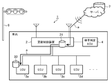
- FIG. 1 is a block diagram showing a configuration of an update control system 1 according to Embodiment 1 of the present invention.
- the update control system 1 is a system that controls updating of an ECU to be updated among the ECUs 3a to 3d (vehicle-mounted electronic control devices) mounted on the vehicle.
- ECUs 3a to 3d vehicle-mounted electronic control devices mounted on the vehicle.
- an update control device 2 and a stop determination ECU Is provided.
- the update control device 2 receives the update data of the ECU to be updated by wireless communication while the vehicle is traveling, and stops after the vehicle is once stopped by turning on a red signal of a traffic light or descending of a circuit breaker at a railroad crossing.
- the ECU to be updated is updated within the stop time until the start of the operation.
- the update data is update data of firmware or software provided in the vehicle-mounted ECU.
- a full image update or a difference image update is used as an update method.
- the update control device 2 has a function of performing wired communication and wireless communication, and has a gateway function for connecting to a different network.
- the wireless communication includes data mobile communication such as LTE or 3G, WiFi, Bluetooth (registered trademark), road-to-vehicle communication, and vehicle-to-vehicle communication.
- Examples of the wired communication include Ethernet (registered trademark), CAN (Controller Area Network), MOST (Media Oriented Systems Transport), and LIN (Local Interconnect Network).
- the ECUs 3a to 3d are electronic control units that control various on-vehicle devices mounted on the vehicle.
- the ECU 3a is an ECU that realizes a control system of an accelerator operation, a brake operation, a steering wheel operation, a vehicle interior lighting, and a headlight
- the ECU 3b uses an external camera, a vehicle interior camera, and a corner sensor to perform an ADAS (Advanced Driver Assistance System). ).
- ADAS Advanced Driver Assistance System
- the update control device 2 inquires an ECU having a dependency relationship with the update target ECU about whether or not the update can be executed. If a response indicating that the update can be executed is confirmed, the update time required for the update to be completed and the stop time are updated. It is determined whether the update of the update target ECU is completed within the stop time.
- the dependency relationship between ECUs is a relationship in which communication is performed between ECUs, and the other ECU performs arithmetic processing using information received from one ECU.
- the ECU 3c is an ECU that calculates the vehicle speed
- the ECU 3d is an ECU that corrects the current position of the vehicle using the vehicle speed
- the ECU 3d corrects the current position of the vehicle using the vehicle speed received from the ECU 3c. Therefore, when the transmission of the vehicle speed signal from the ECU 3c is interrupted, the ECU 3d may be erroneously recognized as an emergency in which the communication line with the ECU 3c is disconnected.
- the update control device 2 inquires of the ECUs that have a dependency relationship with the update target ECU about whether or not the update can be performed, and when there is a response indicating that the update can be performed, updates the target ECU.
- the update of the update target ECU is executed, the communication with the ECU having a dependency on the update is shut down. For this reason, an inquiry about whether or not the update target ECU can be updated can be regarded as an inquiry about whether or not the update target ECU can be shut down from the ECUs having a dependency relationship.
- the stop determination ECU 4 monitors the traffic signal or the level crossing in front of the vehicle and the vehicle speed to determine whether the vehicle has stopped due to the lighting of the red signal of the traffic signal or the descending of the level crossing barrier. For example, the stop determination ECU 4 controls the camera outside the vehicle to recognize the light color of the traffic light or the state of the circuit breaker at the level crossing from the image in front of the vehicle, and recognizes the vehicle speed from the vehicle speed sensor or the brake operation. It is determined whether or not the vehicle has been stopped by turning on a traffic light or lowering the level crossing barrier. When determining that the vehicle has stopped, the stop determination ECU 4 transmits a stop state notification indicating the determination result to the update control device 2 by in-vehicle communication.
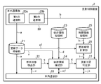
- FIG. 2 is a block diagram showing the configuration of the update control device 2.
- the update control device 2 includes an external communication unit 20, an update data storage unit 21, a stop state detection unit 22, a dependence relationship storage unit 23, a dependence relationship confirmation unit 24, a time information storage unit 25, and an update time calculation unit 26.
- the external communication unit 20 is a communication unit that communicates with an external device by wireless communication, and includes a first communication unit 20a and a second communication unit 20b.
- the first communication unit 20a connects to a wireless network by wireless communication such as LTE or 3G, and acquires update data a from an external device connected to the wireless network.
- the external device is, for example, a server that manages update data of firmware or software provided in the ECU.
- the server transmits update data a including information indicating the firmware or software to be updated and an update program to the update control device 2.
- the update control device 2 specifies an update target ECU from the ECUs 3a to 3d based on the update data a received from the server.
- the second communication unit 20b is a stop time obtaining unit that obtains the stop time b of the vehicle using road-to-vehicle communication or vehicle-to-vehicle communication.
- the stop time b is the time from when the vehicle stops once to when the vehicle starts running.
- the second communication unit 20b may receive the stop time b from a traffic signal or a roadside wireless communication device provided at a railroad crossing by road-to-vehicle communication.
- the roadside wireless communication device is an external device that manages the time during which the red signal of the traffic light is turned on or the time when the crossing barrier at the railroad crossing is descending as the stop time b.
- the second communication unit 20b determines the stop time b by the inter-vehicle communication from the on-vehicle device of the preceding vehicle. May be acquired.
- the update data storage unit 21 is a storage unit that stores the update data a of the update target ECU.
- the update data a received from the server by the first communication unit 20a is stored in the update data storage unit 21.
- the stop state detection unit 22 detects the stop state of the vehicle based on whether or not the stop state notification c from the stop determination ECU 4 has been received.
- the stopped state of the vehicle is a state in which the vehicle is temporarily stopped due to lighting of a red light of a traffic light or dropping of a circuit breaker at a railroad crossing.
- the stop state detection unit 22 detects whether the vehicle is in a stop state based on the stop state notification c received from the stop determination ECU 4 by the in-vehicle communication unit 28, and determines whether the vehicle is in a stop state if the vehicle is in a stop state.
- the notification c is output to the dependency check unit 24.
- the dependency storage unit 23 stores dependency information d indicating a dependency between ECUs of the ECUs 3a to 3d connected to the update control device 2.
- the dependency information d is table information in which information indicating the dependency between ECUs is associated with each ECU.
- the information indicating the dependency between ECUs includes, for example, a destination address in communication between ECUs.
- the dependency check unit 24 inquires of the ECUs 3a to 3d that have a dependency with the update target ECU whether the update target ECU can be updated. For example, the dependency check unit 24 checks the ECU to be updated with reference to the update data a stored in the update data storage unit 21, and determines the ECU of the vehicle based on the stop state notification c input from the stop state detection unit 22. Check the stop condition. The dependency checking unit 24 specifies an ECU having a dependency with the ECU to be updated based on the dependency information d stored in the dependency storage 23. Using the in-vehicle communication unit 28, the dependency relationship checking unit 24 transmits inquiry information e to an ECU having a dependency relationship with the update target ECU to inquire whether the update of the update target ECU can be performed.
- the ECU that has a dependency with the update target ECU transmits response information f to the inquiry information e to the update control device 2.
- the dependency check unit 24 generates response content information g indicating the content of the response information f received by the in-vehicle communication unit 28 and outputs the generated response content information g to the update availability determination unit 27.
- the response content information g is used as a condition by which the update availability determination unit 27 determines whether or not the update is available.
- the time information storage unit 25 stores the start time of the ECU connected to the update control device 2, the end time of the ECU, and time information h, which is a memory writing speed, in association with each ECU.
- the start time of the ECU and the end time of the ECU include the start time of the OS and the end time of the OS if the ECU has an operating system (OS).
- the end time also includes a communication end process between ECUs.
- the update time calculation unit 26 refers to the time information h stored in the time information storage unit 25 and the data size a1 of the update data a stored in the update data storage unit 21 to update the update target ECU. Calculate the required update time i.
- the update availability determination unit 27 determines whether the update of the update target ECU is completed within the stop time b. For example, when the response content information g input from the dependency check unit 24 indicates that the update is executable, the update availability determination unit 27 calculates the stop time b and the update time calculation acquired by the second communication unit 20b. The update time i calculated by the unit 26 is compared to determine whether or not the update of the update target ECU is completed within the stop time b.
- the in-vehicle communication unit 28 communicates with each of the ECUs 3a to 3d and the stop determination ECU 4 via wired communication such as CAN. For example, the in-vehicle communication unit 28 transmits the inquiry information e from the dependency checking unit 24 to ECUs that have a dependency with the ECU to be updated, and receives response information f from these ECUs. Further, the in-vehicle communication unit 28 transmits the update request j from the update availability determination unit 27 to the update target ECU, and receives the update result information k from the update target ECU.
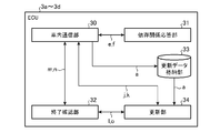
- FIG. 3 is a block diagram showing the configuration of the vehicle-mounted ECU, and shows the functional configuration of the ECUs 3a to 3d shown in FIG.
- each of the ECUs 3a to 3d includes an in-vehicle communication unit 30, a dependency response unit 31, an end confirmation unit 32, and an update unit 34.
- the in-vehicle communication unit 30 communicates with other ECUs and the update control device 2 via wired communication such as CAN.
- the dependency relation response unit 31 generates response information f for the inquiry information e received by the in-vehicle communication unit 30, and transmits the response information f to the update control device 2 using the in-vehicle communication unit 30.
- the termination confirmation unit 32 confirms termination of communication with a dependent ECU when the ECU on which the ECU is mounted is the update target ECU. For example, upon receiving the communication termination request 1 from the updating unit 34, the termination confirmation unit 32 transmits a communication termination notification m to the ECU having a dependency using the in-vehicle communication unit 30. Upon receiving the communication end notification m, the end confirmation unit 32 included in the ECU having the dependency relationship generates response information n indicating whether communication with the update target ECU can be ended, and sends the response information n to the update target ECU using the in-vehicle communication unit 30. Send.
- the end confirmation unit 32 included in the ECU to be updated receives the response information n received from the ECU having a dependency relationship received by the in-vehicle communication unit 30 and outputs information o indicating the content of the response information n to the update unit 34. .
- the update data storage unit 33 is a storage unit that stores the update data a of the update target ECU. Before the update is started by the update request j, the update data a may be stored in the update data storage unit 33.
- the update unit 34 performs a firmware or software update process of the ECU using the update data a stored in the update data storage unit 33. For example, when the update request j is received from the update control device 2 by the in-vehicle communication unit 30 and the information o indicating that the communication with the dependent ECU is permitted to be ended is obtained by the end confirmation unit 32, Then, an update process is performed using the update data a.
- the update unit 34 uses the in-vehicle communication unit 30 to transmit update result information k indicating the result of the update process to the update control device 2.
- the update control device 2 includes a processing circuit for executing processing from step ST1a to step ST8a described later with reference to FIG.
- the processing circuit may be dedicated hardware, or may be a CPU (Central Processing Unit) that executes a program stored in the memory.
- the update control device 2 includes a processing circuit for executing processing from step ST1b to step ST7b, which will be described later with reference to FIG.
- the processing circuit may be dedicated hardware, or may be a CPU that executes a program stored in a memory.
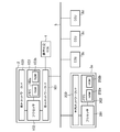
- FIG. 4 is a block diagram showing a hardware configuration for executing software for realizing the functions of the update control system 1.
- the update control device 2 and the ECUs 3a to 3d are connected to each other by a communication bus 5.
- the outside network interface 100 is an interface (hereinafter, referred to as an I / F) for communication connection with a network outside the vehicle.
- the outside-vehicle network I / F 100 is a road-to-vehicle I / F for communicating with a roadside wireless communication device provided on the roadside near a traffic signal or a railroad crossing, and further has a wireless connection for communication connection with a communication network such as the Internet. Communication I / F.
- Examples of the wireless communication I / F include LTE, 3G, WiFi, and Bluetooth (registered trademark) I / Fs.
- Information transmitted and received between the first communication unit 20a and the second communication unit 20b illustrated in FIG. 2 and the external device is relayed by the external network I / F 100.
- the in-vehicle network I / F 101 and the in-vehicle network I / F 200 are I / Fs for performing wired communication between ECUs via the in-vehicle network.
- the in-vehicle network I / F 101 and the in-vehicle network I / F 200 include CAN, Ethernet (registered trademark), MOST, and LIN I / Fs.
- Information transmitted and received between the in-vehicle communication unit 28 shown in FIG. 2 and the in-vehicle communication unit 30 shown in FIG. 3 is relayed by the in-vehicle network I / F 101 and the in-vehicle network I / F 200.
- the processing circuit may be, for example, a single circuit, a composite circuit, a programmed processor, a parallel programmed processor, or an ASIC (Application / Specific / Integrated / Circuit). ), An FPGA (Field-Programmable Gate Array), or a combination thereof.
- the external communication unit 20 the update data storage unit 21, the stop state detection unit 22, the dependency relationship storage unit 23, the dependency relationship confirmation unit 24, the time information storage unit 25, the update time calculation unit 26, the update availability determination
- the functions of the unit 27 and the in-vehicle communication unit 28 may be realized by separate processing circuits, or these functions may be collectively realized by one processing circuit.
- the processing circuits include, for example, a single circuit, a composite circuit, a programmed processor, a parallel programmed processor, an ASIC, an FPGA, or A combination of these applies.
- the functions of the in-vehicle communication unit 30, the dependency response unit 31, the end confirmation unit 32, and the update unit 34 provided in the ECUs 3a to 3d may be realized by separate processing circuits. It may be realized by a circuit.
- the external communication unit 20 When the processing circuit that implements the function of the update control device 2 is the processor 102 illustrated in FIG. 4, the external communication unit 20, the update data storage unit 21, the stop state detection unit 22, the dependency relationship storage unit 23, The functions of the dependency check unit 24, the time information storage unit 25, the update time calculation unit 26, the update availability determination unit 27, and the in-vehicle communication unit 28 are realized by software, firmware, or a combination of software and firmware.
- the software or firmware is described as a program and stored in the memory 103.
- the processor 102 reads out and executes the program stored in the memory 103, so that the external communication unit 20, the update data storage unit 21, the stop state detection unit 22, the dependency storage unit 23, the dependency check, The functions of the unit 24, the time information storage unit 25, the update time calculation unit 26, the update availability determination unit 27, and the in-vehicle communication unit 28 are realized. That is, the update control device 2 includes a memory 103 for storing a program that, when executed by the processor 102, results in the processing from step ST1a to step ST8a shown in FIG.
- These programs include an external communication unit 20, an update data storage unit 21, a stop state detection unit 22, a dependency relationship storage unit 23, a dependency relationship confirmation unit 24, a time information storage unit 25, an update time calculation unit 26, and an update availability determination unit.
- 27 causes the computer to execute the procedure or method of the in-vehicle communication unit 28.
- the memory 103 stores the computer in the external communication unit 20, the update data storage unit 21, the stop state detection unit 22, the dependency relationship storage unit 23, the dependency relationship confirmation unit 24, the time information storage unit 25, the update time calculation unit 26, and the update availability. It may be a computer-readable storage medium storing a program for causing it to function as the determination unit 27 and the in-vehicle communication unit 28.
- the processing circuit that realizes the respective functions of the ECUs 3a to 3d is the processor 201 illustrated in FIG. 4, the functions of the in-vehicle communication unit 30, the dependency relation response unit 31, the end confirmation unit 32, and the update unit 34 included in the ECUs 3a to 3d, respectively.
- the functions of the in-vehicle communication unit 30, the dependency relation response unit 31, the end confirmation unit 32, and the update unit 34 included in the ECUs 3a to 3d respectively.
- the software or firmware is described as a program and stored in the memory 202.
- the processor 201 reads out and executes the program stored in the memory 202, thereby realizing the functions of the in-vehicle communication unit 30, the dependency relation response unit 31, the end confirmation unit 32, and the update unit 34, which are provided in the ECUs 3a to 3d, respectively.
- the ECUs 3a to 3d include a memory 202 for storing a program that, when executed by the processor 201, results in the processing of steps ST1b to ST11b shown in FIG.
- the memory 202 may be a computer-readable storage medium storing a program for causing a computer to function as the in-vehicle communication unit 30, the dependency response unit 31, the end confirmation unit 32, and the update unit 34.
- a RAM (Random Access Memory) 103a and a ROM (Read Only Memory) 103b are used as the memory 103.
- the RAM 103a temporarily stores an execution program executed by the processor 102 and data necessary for executing the program.
- An execution program is stored in the ROM 103b.
- the memory 103 includes a nonvolatile memory such as a flash memory, an EPROM (Erasable Programmable Read Only Memory), and an EEPROM (Electrically-EPROM), a magnetic disk, a flexible disk, an optical disk, a compact disk, a mini disk, Or a DVD.
- the RAM 202a and the ROM 202b are used for the memory 202, similarly to the memory 103.
- the RAM 202a temporarily stores an execution program executed by the processor 201 and data required for executing the program.
- the execution program and the program to be updated are stored in the ROM 202b.
- the external communication unit 20 the update data storage unit 21, the stop state detection unit 22, the dependency relationship storage unit 23, the dependency relationship confirmation unit 24, the time information storage unit 25, the update time calculation unit 26, the update availability determination
- a part of the functions of the unit 27 and the in-vehicle communication unit 28 may be realized by dedicated hardware, and a part may be realized by software or firmware.
- the functions of the external communication unit 20 and the internal communication unit 28 are realized by a processing circuit that is a dedicated hardware, and the update data storage unit 21, the stop state detection unit 22, the dependency storage unit 23, the dependency confirmation unit
- the functions of the 24, the time information storage unit 25, the update time calculation unit 26, and the update availability determination unit 27 are realized by the processor 102 reading and executing the program stored in the memory 103.
- the processing circuit can realize the above functions by hardware, software, firmware, or a combination thereof. This is the same for the ECUs 3a to 3d.
- FIG. 5 is a flowchart showing the operation of the update control system 1, and shows a case where one of the ECUs 3a to 3d is an update target ECU.
- the stop determination ECU 4 determines that the vehicle is in the stopped state, and transmits a stop state notification c to the update control device 2.
- the stop state detection unit 22 checks whether the stop state of the vehicle is detected based on whether the stop state notification c from the stop determination ECU 4 is received (step ST1).
- the processing in FIG. 5 is ended. Note that a series of processes shown in FIG. 5 is executed for each stop by a traffic light or the like while the update control device 2 is running.
- the stop state detection unit 22 When the stop state notification c is received and the stop state of the vehicle is detected (step ST ⁇ b>1; YES), the stop state detection unit 22 outputs the stop state notification c to the dependency check unit 24.
- the dependency check unit 24 checks whether an ECU to be updated exists in the ECUs 3a to 3d connected to the update control device 2 and whether the update data a has been downloaded (step ST2). For example, the dependency check unit 24 refers to the update data a stored in the update data storage unit 21 so that the ECU to be updated exists in the ECUs 3a to 3d, and the update data a is stored in the update data storage unit 21. It is checked in 21 whether or not the download has been completed.
- the processing of FIG. 5 is terminated.
- the update data a that can be updated is data that has been downloaded to the update control device 2 while the vehicle is running.
- step ST3 if the update target ECU exists in the ECUs 3a to 3d and the update data a has been downloaded (step ST2; YES), the dependency relationship checking unit 24 and the update availability determination unit 27 update the update target ECU. It is determined whether or not execution is possible (step ST3). Note that this update availability determination will be described in detail with reference to FIG. When the update permission / non-permission determination unit 27 determines that the update of the update target ECU is not executable (step ST3; NO), the processing in FIG. 5 is ended.
- step ST4 When the update availability determination unit 27 determines that the update of the update target ECU is executable (step ST3; YES), the update availability determination unit 27 issues an update request instructing the update target ECU to execute the update (step ST4).
- the update data a Before the update is started by the update request j, the update data a may be stored in the update data storage unit 33.
- the update target ECU executes the firmware or software update process using the update data a received from the update control device 2. Then, the update target ECU uses the in-vehicle communication unit 30 to transmit the update result information k indicating whether or not the update was successful to the update control device 2.
- the in-vehicle communication unit 28 included in the update control device 2 receives the update result information k from the update target ECU (step ST5). If the update result information k indicates that the update was successful, the update of the ECU to be updated is completed. On the other hand, when the update result information k indicates that the update has failed, the series of processes in FIG. 5 is repeatedly executed until the update of the update target ECU is completed.
- FIG. 6 is a flowchart showing the update control method according to the first embodiment, and shows the details of step ST4 shown in FIG.
- the dependency relationship checking unit 24 inquires of the ECUs having a dependency relationship with the update target ECU whether or not the update of the update target ECU can be performed (step ST1a).
- the dependency check unit 24 specifies all ECUs that have a dependency with the update target ECU based on the dependency information d stored in the dependency storage unit 23.
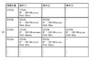
- FIG. 7 is a diagram showing an example of the dependency information d.
- the destination of the ECU in the in-vehicle communication between the ECUs is set as information indicating the dependency with the ECU to be updated. If the in-vehicle communication is Ethernet (registered trademark), the ECU destination is the IP (Internet Protocol) address and port number of the ECU. If the in-vehicle communication is CAN, the CAN-received by the ECU to which the communication is connected is received. ID.
- the ECU 3a has a dependency (1) of performing in-vehicle communication with the ECU 3c as shown in FIG.
- the ECU to be updated is the ECU 3c
- dependency (1) for performing in-vehicle communication with the ECU 3a
- a dependency (2) for performing in-vehicle communication with the ECU 3b
- a dependency for performing in-vehicle communication with the ECU 3d There is (3).
- the dependency checking unit 24 refers to the dependency information d shown in FIG. 7 to select the ECU 3c and the ECU 3d having a dependency with the ECU 3b from the ECUs 3a, 3c, and 3d. To identify. Subsequently, the dependency check unit 24 outputs the inquiry information e to the in-vehicle communication unit 28, and transmits the inquiry information e to the ECUs 3c and 3d that have a dependency with the ECU 3b to be updated. When a plurality of ECUs are to be inquired, the in-vehicle communication unit 28 may distribute the inquiry information e by broadcast.
- FIG. 8 is an explanatory diagram showing a process for confirming the dependence of the ECU in the first embodiment.
- a description will be given on the assumption that the ECU 3a is an update target and the ECU 3c has a dependency with the ECU 3a. Further, it is assumed that the vehicle is once stopped by the red light of the traffic light 6 and the update data a has been downloaded from the server 7 to the update control device 2.
- the dependency check unit 24 included in the update control device 2 transmits information for inquiring whether there is no problem in updating to the ECU 3a to be updated, using the in-vehicle communication unit 28.
- the dependence response unit 31 included in the ECU 3a to be updated sends the response information f to the update control device 2 using the in-vehicle communication unit 30 as an information communication process (2). Send.
- the dependency response unit 31 manages the communication between the ECU 3a to be updated and the ECU 3b having the dependency in the communication states (A) to (C), and stores the response information f based on the current communication state. Determine the content.
- the communication state (A) is a state in which the ECU 3a is not communicating.
- the communication state (B) is a state in which the ECU 3a periodically communicates with the ECU 3c. In the communication state (B), the ECU 3a does not communicate with the ECU 3c except during the communication cycle. In the communication state (C), the ECU 3a and the ECU 3c are currently communicating, and are performing a process using information obtained by the communication.
- the dependency response unit 31 included in the ECU 3a to be updated specifies a state corresponding to the current communication state from the communication states (A) to (C), and sends response information f indicating the specified communication state to the in-vehicle communication unit 30. Is transmitted to the update control device 2 by using the information communication process (information communication process (2)).
- the dependency check unit 24 included in the update control device 2 transmits the inquiry information e to the ECU 3c having a dependency with the ECU 3a to be updated, using the in-vehicle communication unit 28.
- the dependence response unit 31 included in the ECU 3c transmits the response information f to the update control device 2 using the in-vehicle communication unit 30 as an information communication process (2a).
- the dependency response unit 31 provided in the ECU 3c manages communication with the ECU 3a to be updated in communication states (A) to (C).
- the dependence response unit 31 provided in the ECU 3c specifies a state corresponding to the current communication state from the communication states (A) to (C), and sends response information f indicating the specified communication state to the in-vehicle communication unit 30. And transmits it to the update control device 2 (information communication step (2a)).
- the dependency check unit 24 checks whether or not there is a response indicating that the update can be executed from all ECUs having a dependency with the update target ECU based on the response information f (step ST2a). For example, when the communication state in the response information f is the communication state (A) or the communication state (B), the dependency check unit 24 determines that the response information f indicates that the update is executable, and Is output to the update permission / inhibition determination unit 27 indicating that the execution is possible. On the other hand, if the communication state in the response information f is the communication state (C), the dependency check unit 24 determines that the response information f indicates that update cannot be executed, and the response content indicating that update cannot be executed. The information g is output to the update availability determination unit 27.
- the update permission / inhibition determination section 27 sends the update time i to the update time calculation section 26 so as to calculate the update time i. Instruct.
- the update time calculation unit 26 calculates the update time i of the ECU to be updated (step ST3a). For example, the update time calculation unit 26 refers to the time information h stored in the time information storage unit 25 and the data size a1 of the update data a stored in the update data storage unit 21 to determine the update target ECU. The update time i required for the update is calculated.
- FIG. 9 is a diagram showing an example of time information h according to the first embodiment.
- the time information h shown in FIG. 9 includes an ECU start time (millisecond), a writing speed of the ROM 202b (millisecond / byte), an end time of the operation of the ECU (millisecond), and the number of times the ECU has been started and the number of times the ECU has been ended
- And spare time (milliseconds) are table information associated with each ECU.
- the ROM 202b stores an execution program and an update program.
- the update time calculation unit 26 calculates the update time i according to the following equation (1) using the time information h and the data size a1 of the update data a.
- A is the activation time of the update target ECU
- B is the number of activations of the update target ECU
- C is the writing speed of the ROM 202b included in the update target ECU.
- D is the data size a1 of the update data a.
- E is the end time of the operation of the update target ECU
- F is the end count of the update target ECU
- G is the spare time.
- Update time (ms) (A ⁇ B) + (C ⁇ D) + (E ⁇ F) + G (1)
- the update time i of the ECU 3a is calculated as follows using the time information h and the data size a1 of the update data a shown in FIG. Is done.
- the start time A and the end time E of the ECU may be an average time when the start and end of the ECU are repeated about several tens of times.
- the number of start times B and the number of end times F of the ECU are the number of start and end times in accordance with the reset of the ECU executed by updating the firmware or software of the ECU, and differ depending on the configuration of the memory area of the ROM 202b.
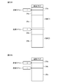
- FIG. 10A is a diagram illustrating a configuration of a memory area of the ROM 202b provided in the update target ECU.
- FIG. 10B is a diagram illustrating a configuration of a memory area of the ROM 202b included in the ECU having a dependency relationship with the ECU to be updated. 10A and 10B, the ECU to be updated is the ECU 3a.
- the ROM 202b includes a memory area 21a, a memory area SW (1), and a memory area SW (2) in addition to a memory area in which a startup flag is stored.
- the memory area 21a functions as the update data storage unit 21, and stores the update data a.
- the memory area SW (1) includes a memory area 34a and a memory area 35a.
- a program for realizing the function of the update unit 34 is stored in the memory area 34a.
- a program that realizes software to be updated other than the update unit 34 is stored.
- the memory area SW (2) includes a memory area 34b and a memory area 35b.
- the memory area 34b stores a program for realizing the function of the update unit 34
- the memory area 35b stores a program for realizing software to be updated other than the update unit 34.
- the processor 201 executes the program stored in the memory area SW (1). That is, when updating the ECU 3a, the program stored in the memory area 34a is executed by the processor 201, and the updating unit 34 is activated.
- the update unit 34 updates the program stored in the memory area SW (2) using the update data a read from the memory area 21a. Thereafter, after the activation label "2" is set at the head address of the updated memory area SW (2), the ECU 3a is reset to validate the update of the program stored in the memory area SW (2). You. That is, the operation of the ECU 3a is terminated and restarted. At this time, the number of terminations and the number of activations of the ECU 3a are each one. When the ECU 3a is restarted, the program stored in the memory area 34b is executed by the processor 201, and the updating unit 34 is started.
- the ROM 202b shown in FIG. 10B includes a memory area 21a, a memory area 34c, and a memory area 35c in addition to the memory area storing the activation flag.
- the memory area 21a functions as the update data storage unit 21, and stores the update data a.
- the memory area 34c stores a program for realizing the function of the update unit 34, and the memory area 35c stores a program for realizing software to be updated other than the update unit 34.
- the processor 201 executes the program stored in the memory area 35c. That is, when the ECU 3a is updated, a program other than the update unit 34 is executed by the processor 201. Therefore, the ECU 3a is reset after the activation label “2” is set to the head address of the memory area 34c. Thus, the operation of the ECU 3a is terminated and restarted.
- the update unit 34 is activated by resetting the ECU 3a.
- the update unit 34 updates the program described in the memory area 35c using the update data a read from the memory area 21a.
- the activation label “1” is set at the head address of the updated memory area 35c, and then the ECU 3a is reset to validate the update of the program stored in the memory area 35c.
- the operation of the ECU 3a is terminated and restarted.
- the contents of the program stored in the memory area 35c are activated.
- the second communication unit 20b provided in the external communication unit 20 acquires the stop time b (step ST4a).
- the second communication unit 20b receives the stop time b from a traffic light or a roadside wireless communication device provided at a railroad crossing.
- the stop time b is a time during which the red signal of the traffic light is on or a time at which the crossing barrier at the level crossing is descending, and the vehicle is temporarily stopped by the lighting of the red signal at the traffic signal or the lowering of the crossing at the level crossing. It is the time from starting to running.
- the stop time b acquired by the second communication unit 20b is output to the update availability determination unit 27.
- the update availability determination unit 27 compares the stop time b input from the second communication unit 20b with the update time i calculated by the update time calculation unit 26 (step ST5a), and determines that the stop time b is the update time i. It is determined whether or not it is longer (step ST6a). When it is determined that the stop time b is less than or equal to the update time i (step ST6a; NO), or when any of the ECUs having a dependency with the update target ECU responds that the update cannot be executed by the dependency check unit 24. (Step ST2a; NO), the update availability determination unit 27 determines that the update of the update target ECU cannot be executed (Step ST7a). Thereafter, the processing in FIG. 6 ends.
- step ST6a when it is determined that the stop time b is longer than the update time i (step ST6a; YES), the update availability determination unit 27 determines that the update of the update target ECU can be performed (step ST8a). Thereafter, the update availability determination unit 27 transmits an update request j instructing the update target ECU to execute the update using the in-vehicle communication unit 28, and ends the processing in FIG.
- FIG. 11 is a flowchart illustrating an update process of the update target ECU according to the first embodiment.
- FIG. 12 is an explanatory diagram illustrating processing from the end of communication between ECUs to the notification of an update result.
- the ECU 3a is an update target and the ECU 3c has a dependency with the ECU 3a.
- the update availability determination unit 27 included in the update control device 2 transmits an update request j for instructing the update target ECU 3a to execute update (see the information communication process (1 shown in FIG. 12). )).
- the in-vehicle communication unit 30 provided in the ECU 3a receives the update request j from the update control device 2 (step ST1b).
- the update request j received by the in-vehicle communication unit 30 is output to the update unit 34.
- the update unit 34 Upon receiving the update request j, the update unit 34 outputs a communication end request 1 to the end confirmation unit 32.
- the termination checking unit 32 included in the ECU 3a determines whether or not there is an ECU that has a dependency relationship with the ECU 3a to be updated among the ECUs 3b to 3d connected to the updating control device 2. Is confirmed (step ST2b). For example, the end confirmation unit 32 confirms whether there is a dependency between the ECU 3a and another ECU based on a communication state between the ECU 3a and another ECU. If the communication state of the ECU 3a is the communication state (A) (a state in which the ECU 3a is not communicating with the ECU) when the update request j from the update control device 2 is received, the processing of step ST3b is omitted. May be.
- the end confirmation unit 32 checks whether there is no problem even if the update target ECU 3a shuts down at this time.
- the communication unit 30 transmits a communication end notification m to the ECU that is dependent on the ECU 3a (step ST3b).
- the communication end notification m is transmitted from the ECU 3a to the ECU 3c (the information communication step (2) in FIG. 12).
- the termination confirmation unit 32 included in the ECU 3c changes the communication state with the ECU 3a to the above-described communication state (A) (a state in which communication is not performed). It controls the in-vehicle communication unit 30. For example, when the ECU 3c and the ECU 3a are communicating in the communication state (B) (periodic communication), the timer for the periodic communication is stopped, and the communication with the ECU 3a is interrupted.
- the end confirmation unit 32 included in the ECU 3c controls the in-vehicle communication unit 30 so that communication with the ECU 3a is not performed until the update of the ECU 3a is completed. Good.
- the termination confirmation unit 32 included in the ECU 3c when the communication with the ECU 3a to be updated can be transited to a communication state that does not cause any problem, indicates that the communication with the ECU 3a to be updated can be terminated. n is transmitted to the ECU 3a to be updated using the in-vehicle communication unit 30 (the information communication step (3) in FIG. 12).
- the end confirmation unit 32 included in the ECU 3a to be updated confirms whether or not responses have been received from all ECUs that are dependent on the ECU 3a (step ST4b).
- the termination confirmation unit 32 confirms whether or not response information n indicating that communication with the ECU 3a can be terminated has been received from all of the dependent ECUs.
- the end confirmation unit 32 outputs information o indicating the content of the response information n to the update unit 34.
- the updating unit 34 determines whether or not response information n indicating that communication with the ECU 3a to be updated can be ended is received based on the information o from the end checking unit 32.
- step ST4b When the response information n indicating that the communication with the ECU 3a can be ended is received from all the dependent ECUs (step ST4b; YES), or there is no ECU dependent on the ECU to be updated. In this case (step ST2b; NO), the updating unit 34 starts updating (step ST5b). Thereby, the update of the firmware or software included in the ECU 3a is started.
- step ST4b when response information n indicating that communication with the ECU 3a cannot be terminated is received from any of the ECUs having a dependency (step ST4b; NO), the update unit 34 determines that the update has failed. A determination is made (step ST6b). When the processing in step ST5b or the processing in step ST6b is completed, the update unit 34 notifies the update result to the update control device 2 (step ST7b). For example, the update unit 34 uses the in-vehicle communication unit 30 to transmit the update result information k indicating the result of the update process to the update control device 2 (the information communication process (4) in FIG. 12).
- FIG. 13 is an explanatory diagram illustrating the download processing of the update data according to the first embodiment.
- the first communication unit 20a included in the update control device 2 downloads the update data a from the server 7 that manages the update data using mobile data communication while the vehicle is running.
- the update data a downloaded by the first communication unit 20a is temporarily stored in the update data storage unit 21 provided in the update control device 2, as shown in FIG.
- the reason that the update data a is temporarily stored in the update data storage unit 21 is that wireless communication between the server 7 and the first communication unit 20a is more unstable than wired communication, and that a plurality of ECUs In the case of, the data size of the update data a increases accordingly, and it is necessary to temporarily store the data.
- the data size is assigned to the update data a stored in the update data storage unit 21 and transmitted to the ECU to be updated by the in-vehicle communication unit 28.
- the ECU to be updated is the ECU 3a.
- the in-vehicle communication unit 30 provided in the ECU 3a stores the update data a in the update data storage unit 33.
- the update unit 34 updates the firmware or software included in the ECU 3a using the update data a stored in the update data storage unit 33.
- the update control device 2 when the update control device 2 according to the first embodiment responds from the ECU having the dependency relationship with the update target ECU that the update can be executed, the update control device 2 stops the vehicle once and starts running. It is determined whether or not the update of the update target ECU is completed within the stop time b. For example, when it is determined that the update of the ECU is completed within the stop time b from when the vehicle stops at a traffic light at the red light of the traffic light or when the circuit breaker at the railroad crossing starts, the update of the ECU is performed. . Thus, the ECU can be updated without intentionally parking the vehicle.
- the second communication unit 20b acquires the stop time b from the external device. For example, the second communication unit 20b acquires, as the stop time b, a time during which the red light of the traffic light is turned on or a time when the crossing barrier at the railroad crossing is descending. Thereby, the update control device 2 can obtain an accurate stop time at a traffic light or a railroad crossing.
- the update control device 2 includes a dependency storage unit 23 in which dependency information d indicating a dependency between ECUs is stored.
- the dependency relationship checking unit 24 inquires of the ECU whose dependency relationship with the update target ECU has been confirmed based on the dependency relationship information d stored in the dependency relationship storage unit 23 whether or not the update of the update target ECU can be performed.
- the update control device 2 can accurately recognize the ECU having a dependency relationship with the update target ECU and inquire whether the update target ECU can be updated.
- the update time calculation unit 26 calculates the update time i based on the time required for shutting down, starting up, and rewriting the memory of the ECU to be updated. Thereby, the update control device 2 can calculate an accurate update time i.
- the update control system 1 has the configuration shown in FIG. 1, so that the ECU can be updated without intentionally parking the vehicle.
- the update control method according to the first embodiment since the series of processes illustrated in FIG. 6 is executed, the ECU can be updated without intentionally parking the vehicle, as described above.
- Embodiment 2 when a plurality of ECUs are to be updated, the order in which the updates are performed is determined according to the priority of the update, and the update is performed for each ECU in the determined order.
- the update availability determination is executed for the update having the higher priority.
- the priority is a value assigned in accordance with the urgency of the update, and the higher the priority, the higher the urgency and the quicker it is necessary to respond.
- the configuration of the update control device according to the second embodiment and the configuration of the update control system according to the second embodiment are the same as those of the first embodiment. Therefore, in the following description, FIG. 1, FIG. 2 and FIG. 3 are referred to for the components of the second embodiment.
- FIG. 14 is a flowchart illustrating an update control method according to Embodiment 2 of the present invention.
- all of the ECUs 3a to 3d are update target ECUs.
- the vehicle is temporarily stopped before the processing of FIG. 14 is executed due to lighting of a red light of a traffic light or dropping of a crossing barrier at a railroad crossing.
- the stop determination ECU 4 determines that the vehicle is in the stopped state, and transmits a stop state notification c to the update control device 2.
- the stop state detection unit 22 checks whether or not the stop state of the vehicle has been detected based on whether or not the stop state notification c from the stop determination ECU 4 has been received (step ST1c). When the stop state notification c is not received and the stop state of the vehicle is not detected (step ST1c; NO), the processing in FIG. 14 ends. Note that a series of processing illustrated in FIG. 14 is periodically executed while the update control device 2 is running.
- the stop state detection unit 22 When the stop state notification c is received and the stop state of the vehicle is detected (step ST1c; YES), the stop state detection unit 22 outputs the stop state notification c to the dependency check unit 24.
- the dependency check unit 24 checks whether an ECU to be updated exists in the ECUs 3a to 3d connected to the update control device 2 and whether the update data a has been downloaded (step ST2c). If the update target ECU does not exist or the update data a has not been downloaded (step ST2c; NO), the processing in FIG. 14 ends.
- step ST3c the dependency check unit 24 checks whether there are a plurality of update target ECUs.
- step ST3c if there is only one ECU to be updated (step ST3c; NO), the process proceeds to step ST5c.
- the dependency check unit 24 notifies this to the update availability determination unit 27.
- the update availability determination unit 27 determines an ECU to be updated from among a plurality of update target ECUs (step ST4c). For example, the update availability determination unit 27 extracts the priority assigned to each update from the update data a stored in the update data storage unit 21, and determines the ECU with the highest update priority as the ECU that performs the update. judge.
- step ST5c determines whether the update of the ECU determined in step ST4c is executable. Note that this update availability determination is the same as the process described with reference to FIG. 6 in the first embodiment.
- step ST5c determines whether the update of the update target ECU is not executable by the update availability determination unit 27 (step ST5c; NO).
- the update availability determination unit 27 determines that the update of the update target ECU is executable (step ST5c; YES)
- the update availability determination unit 27 issues an update request to instruct the update target ECU to execute the update (step ST6c).
- the update availability determination unit 27 transmits the update request j to the update target ECU using the in-vehicle communication unit 28, and transmits the update data a temporarily stored in the update data storage unit 21 to the update target ECU. I do.
- the update target ECU executes the firmware or software update process using the update data a received from the update control device 2. Then, the update target ECU uses the in-vehicle communication unit 30 to transmit the update result information k indicating whether or not the update was successful to the update control device 2.
- the in-vehicle communication unit 28 included in the update control device 2 receives the update result information k from the update target ECU (step ST7c).
- the update availability determination unit 27 determines that the update target ECU that has not been updated remains among the plurality of update target ECUs determined in step ST3c, and the time required to complete the update is the current stop time. It is determined whether or not b remains (step ST8c). For example, the update availability determination unit 27 determines that there is an update target ECU for which the update process has not been executed, and that the time of the difference obtained by subtracting the time required for the immediately preceding update (the update time i in the immediately preceding update) from the stop time b is equal to the threshold. It is determined based on whether it is longer than
- step ST8c If the update target ECUs for which the update process has not been executed remain or the stop time b required for completing the update does not remain (step ST8c; NO), the process in FIG. 14 is terminated. Even in the case where it is determined in step ST5c that the update of the ECU having the highest update priority cannot be performed, the determination of step ST8c is performed, so that the ECU having the highest update priority is assigned in order from the ECU having the next highest update priority. , The execution of the update can be determined.
- the update availability determination unit 27 determines The process returns to step ST3c.
- the update availability determination unit 27 determines, for example, the difference between the update time i and the stop time b in the ECU having the highest update priority minus the time required for the immediately preceding update (the update time i in the immediately preceding update). Compare with time. Then, the update availability determination unit 27 determines that the update can be executed if the difference time is longer than the update time i, and determines that the update cannot be executed if the difference time is equal to or less than the update time.
- the update possibility determination unit 27 determines the update target ECUs within the stop time in the order of the update priority in the order of the update priority. It is determined whether or not the update is completed. As a result, even when a plurality of updates are requested at the same time, the update with the higher priority and the highest priority is performed. Further, a plurality of updates can be performed within the stop time b.
- Embodiment 3 when there is an update performed simultaneously by a plurality of ECUs or an update performed by a plurality of ECUs according to an update order, the total time obtained by adding the update times of the plurality of ECUs is compared with the stop time to determine whether or not the update is possible.
- Execute The configuration of the update control device according to the third embodiment and the configuration of the update control system according to the third embodiment are the same as those of the first embodiment. Therefore, in the following description, FIG. 1, FIG. 2 and FIG. 3 are referred to for the components of the third embodiment.
- firmware or software included in a plurality of ECUs is updated at the same time or updated in accordance with the update order, it is necessary to ensure consistency of the updated versions. For example, consider a case where the ECU 3a and the ECU 3c operate with the same version of software. In this case, it is possible to update the version 1.0.0 of the software included in the ECU 3a to 2.0.0, and to update the version 1.0.0 of the software included in the ECU 3c to 2.0.0. . However, it is not possible to update only the software version of the ECU 3c to 2.0.0 without updating the software version 1.0.0 of the ECU 3a.
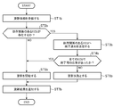
- FIG. 15 is a flowchart showing the update control method according to Embodiment 3 of the present invention, and shows a series of processes corresponding to the process of step ST5c in FIG.
- the dependency relationship checking unit 24 inquires of the ECUs having the dependency relationship with the ECU to be updated whether the update of the ECU to be updated is executable (step ST1d). For example, the dependency check unit 24 specifies all ECUs having a dependency for each update target ECU based on the dependency information d stored in the dependency storage unit 23.
- the dependency confirmation unit 24 determines based on the response information f received from the dependent ECU. Then, it is confirmed whether or not there is a response indicating that the update can be executed from all the ECUs having a dependency relationship for each ECU to be updated (step ST2d). For example, when the response information f indicates that the update is executable, the dependency relationship checking unit 24 outputs the response content information g indicating that the update is executable to the update availability determination unit 27. On the other hand, when the response information f indicates that the update cannot be performed, the dependency relationship checking unit 24 outputs the response content information g indicating that the update cannot be performed to the update availability determination unit 27.
- the update time calculation unit 26 shifts to a repetition loop for the number of the update target ECUs. In this repetition loop, the update time calculation unit 26 calculates an update time i for each ECU to be updated (step ST3d).
- the update time calculation unit 26 refers to the time information h stored in the time information storage unit 25 and the data size a1 of the update data a for each update stored in the update data storage unit 21. The update time i required for the update for each update target ECU is calculated.
- the second communication unit 20b included in the external communication unit 20 acquires the stop time b (step ST4d). For example, the second communication unit 20b receives the stop time b from a traffic light or a roadside wireless communication device provided at a railroad crossing. The stop time b acquired by the second communication unit 20b is output to the update availability determination unit 27.
- the update availability determination unit 27 compares the stop time b input from the second communication unit 20b with the total time of the update time i calculated for each update target ECU by the update time calculation unit 26 (step ST5d). It is determined whether or not the stop time b is longer than the total time (step ST6d). When it is determined that the stop time b is equal to or less than the total time (step ST6d; NO), or when any of the ECUs having a dependency with the update target ECU responds that the update cannot be executed by the dependency relationship checking unit 24. (Step ST2d; NO), the update availability determination unit 27 determines that the update of the update target ECU is not executable (Step ST7d).
- step ST6d When it is determined that the stop time b is longer than the total time (step ST6d; YES), the update availability determination unit 27 determines that the update of the update target ECU is executable (step ST8d). Thereafter, the update permission / inhibition determination unit 27 transmits an update request j for instructing the update target ECU to execute the update using the in-vehicle communication unit 28, and ends the processing in FIG.
- step ST7d when it is determined in step ST7d that the update of the update target ECU cannot be performed, the update availability determination unit 27 excludes the ECUs that have been determined to be not executable and the plurality of ECUs having the update order from the update target ECU ( Step ST9d).
- the update availability determination unit 27 determines the update target ECU that has not been updated regardless of the update order. Therefore, when the process of FIG. 15 is completed and the process returns to the process of FIG. 14, the update order is not considered in step ST8c. Are excluded from the update target ECUs.
- the update control device 2 determines whether the update of the plurality of ECUs to be updated is completed within the stop time b.
- the update availability determination unit 27 determines the longest update time i among the update times i calculated for each ECU by the update time calculation unit 26. And whether or not the update of the plurality of ECUs to be updated is completed within the stop time b.
- the ECU can be updated without intentionally parking the vehicle.
- the update availability determination unit 27 updates the update time calculated for each ECU by the update time calculation unit 26.
- the total time of i is calculated, and the total time is compared with the stop time b to determine whether the update of the plurality of ECUs to be updated is completed within the stop time b.
- the update control device can update the in-vehicle ECU without intentionally parking the vehicle, and thus can be used in an update control system that updates the in-vehicle ECU by OTA.
- 1 update control system 2 update control device, 3a, 3b, 3c, 3d ECU, 4 stop judgment ECU, 5 communication bus, 6 traffic light, 7 server, 20 outside communication unit, 20a first communication unit, 20b second Communication unit, 21, 33 update data storage unit, 21a, 34a, 34b, 34c, 35a, 35b, 35c memory area, 22 stop state detection unit, 23 dependency storage unit, 24 dependency confirmation unit, 25 time information storage unit , 26 update time calculation unit, 27 update availability determination unit, 28, 30 in-vehicle communication unit, 31 dependency relation response unit, 32 end confirmation unit, 33 update data storage unit, 34 update unit, 100 external network I / F, 101, 200 ⁇ in-vehicle network I / F, 102, 201 ⁇ processor, 103, 202 ⁇ memory, 103a, 202 RAM, 103b, 202b ROM.
Landscapes
- Engineering & Computer Science (AREA)
- General Engineering & Computer Science (AREA)
- Theoretical Computer Science (AREA)
- Software Systems (AREA)
- Physics & Mathematics (AREA)
- General Physics & Mathematics (AREA)
- Computer Security & Cryptography (AREA)
- Stored Programmes (AREA)
Abstract
Selon l'invention, dans le cas où une réponse indiquant qu'une mise à jour peut être exécutée est donnée par une ECU embraquée ayant une relation de dépendance avec une ECU embarquée faisant l'objet de la mise à jour, un dispositif de commande de mise à jour (2) détermine si la mise à jour de l'ECU faisant l'objet de la mise à jour est achevée au cours d'une période d'arrêt commençant au moment où le véhicule est arrêté et se terminant au moment où le véhicule démarre.
Priority Applications (5)
| Application Number | Priority Date | Filing Date | Title |
|---|---|---|---|
| US17/253,709 US11726771B2 (en) | 2018-06-29 | 2018-06-29 | Update control device, update control system, and update control method |
| JP2020527146A JP6786013B2 (ja) | 2018-06-29 | 2018-06-29 | 更新制御装置、更新制御システムおよび更新制御方法 |
| DE112018007680.6T DE112018007680T5 (de) | 2018-06-29 | 2018-06-29 | Aktualisierungssteuervorrichtung, Aktualisierungssteuersystem und Aktualisierungssteuerverfahren |
| CN201880094900.3A CN112313618B (zh) | 2018-06-29 | 2018-06-29 | 更新控制装置、更新控制系统和更新控制方法 |
| PCT/JP2018/024899 WO2020003515A1 (fr) | 2018-06-29 | 2018-06-29 | Dispositif de commande de mise à jour, système de commande de mise à jour et procédé de commande de mise à jour |
Applications Claiming Priority (1)
| Application Number | Priority Date | Filing Date | Title |
|---|---|---|---|
| PCT/JP2018/024899 WO2020003515A1 (fr) | 2018-06-29 | 2018-06-29 | Dispositif de commande de mise à jour, système de commande de mise à jour et procédé de commande de mise à jour |
Publications (1)
| Publication Number | Publication Date |
|---|---|
| WO2020003515A1 true WO2020003515A1 (fr) | 2020-01-02 |
Family
ID=68984795
Family Applications (1)
| Application Number | Title | Priority Date | Filing Date |
|---|---|---|---|
| PCT/JP2018/024899 Ceased WO2020003515A1 (fr) | 2018-06-29 | 2018-06-29 | Dispositif de commande de mise à jour, système de commande de mise à jour et procédé de commande de mise à jour |
Country Status (5)
| Country | Link |
|---|---|
| US (1) | US11726771B2 (fr) |
| JP (1) | JP6786013B2 (fr) |
| CN (1) | CN112313618B (fr) |
| DE (1) | DE112018007680T5 (fr) |
| WO (1) | WO2020003515A1 (fr) |
Cited By (9)
| Publication number | Priority date | Publication date | Assignee | Title |
|---|---|---|---|---|
| JP2021149698A (ja) * | 2020-03-19 | 2021-09-27 | 本田技研工業株式会社 | ソフトウェア書換装置 |
| WO2022021191A1 (fr) * | 2020-07-30 | 2022-02-03 | 华为技术有限公司 | Procédé, appareil et système de mise à niveau de logiciel |
| JP2022022833A (ja) * | 2020-07-08 | 2022-02-07 | トヨタ自動車株式会社 | ソフトウェア更新装置、方法、プログラムおよび車両 |
| JP2022102142A (ja) * | 2020-12-25 | 2022-07-07 | 本田技研工業株式会社 | 制御システム、移動体、制御方法及びプログラム |
| US20220308857A1 (en) * | 2021-03-25 | 2022-09-29 | Honda Motor Co., Ltd. | Control device and terminal device |
| WO2023068019A1 (fr) * | 2021-10-20 | 2023-04-27 | 株式会社小糸製作所 | Système de véhicule |
| JP2023096831A (ja) * | 2021-12-27 | 2023-07-07 | 本田技研工業株式会社 | 装置システム |
| US20230418586A1 (en) * | 2020-11-27 | 2023-12-28 | Sony Group Corporation | Information processing device, information processing method, and information processing system |
| WO2024062897A1 (fr) * | 2022-09-22 | 2024-03-28 | 株式会社アドヴィックス | Système de commande et procédé de mise à jour de logiciel |
Families Citing this family (9)
| Publication number | Priority date | Publication date | Assignee | Title |
|---|---|---|---|---|
| JP7124627B2 (ja) * | 2018-10-16 | 2022-08-24 | 株式会社オートネットワーク技術研究所 | 車載更新装置、更新処理プログラム及び、プログラムの更新方法 |
| US11074167B2 (en) * | 2019-03-25 | 2021-07-27 | Aurora Labs Ltd. | Visualization of code execution through line-of-code behavior and relation models |
| JP7502014B2 (ja) * | 2019-10-31 | 2024-06-18 | トヨタ自動車株式会社 | 車両用制御装置、プログラム更新方法、及びプログラム更新システム |
| JP7310570B2 (ja) * | 2019-11-27 | 2023-07-19 | 株式会社オートネットワーク技術研究所 | 車載更新装置、プログラム及び、プログラムの更新方法 |
| WO2022004447A1 (fr) * | 2020-07-03 | 2022-01-06 | ソニーグループ株式会社 | Dispositif de traitement d'informations, procédé de traitement d'informations, système de traitement d'informations et programme |
| JP7540401B2 (ja) * | 2021-06-22 | 2024-08-27 | トヨタ自動車株式会社 | センタ、otaマスタ、方法、プログラム、及び車両 |
| KR20230017634A (ko) * | 2021-07-28 | 2023-02-06 | 현대자동차주식회사 | 차량의 ota 업데이트 제어 장치 및 그 방법 |
| US12373193B2 (en) * | 2022-09-23 | 2025-07-29 | Dell Products, L.P. | Systems and methods for coordinated firmware update using multiple remote access controllers |
| JP7579309B2 (ja) * | 2022-09-28 | 2024-11-07 | 本田技研工業株式会社 | 制御装置、及び、制御方法 |
Citations (8)
| Publication number | Priority date | Publication date | Assignee | Title |
|---|---|---|---|---|
| WO2005059862A1 (fr) * | 2003-12-15 | 2005-06-30 | Hitachi, Ltd. | Procede de mise a jour des informations contenues dans un appareil de commande monte sur vehicule, systeme de communication de la mise a jour des informations, appareil de commande monte sur vehicule et station de base de gestion des informations |
| JP2005182265A (ja) * | 2003-12-17 | 2005-07-07 | Nikon Corp | 電子機器および電子機器のソフトウェア更新用プログラム |
| JP2009053920A (ja) * | 2007-08-27 | 2009-03-12 | Auto Network Gijutsu Kenkyusho:Kk | 車載用電子制御ユニットのプログラム管理システム |
| JP2010277397A (ja) * | 2009-05-29 | 2010-12-09 | Brother Ind Ltd | 周辺装置、プログラム、及び、ネットワークシステム |
| WO2015033660A1 (fr) * | 2013-09-09 | 2015-03-12 | 日本電気株式会社 | Système de cellule de stockage d'énergie, procédé pour mettre à jour un système de cellule de stockage d'énergie et programme |
| JP2016110372A (ja) * | 2014-12-05 | 2016-06-20 | 富士通株式会社 | 情報処理装置、更新時間推定プログラム、及び更新時間推定方法 |
| JP2017097590A (ja) * | 2015-11-24 | 2017-06-01 | アラクサラネットワークス株式会社 | 通信装置、及び管理装置 |
| WO2018079006A1 (fr) * | 2016-10-27 | 2018-05-03 | 住友電気工業株式会社 | Dispositif de commande, procédé de mise à jour de programmes, et programme informatique |
Family Cites Families (21)
| Publication number | Priority date | Publication date | Assignee | Title |
|---|---|---|---|---|
| DE10038096A1 (de) * | 2000-08-04 | 2002-02-14 | Bosch Gmbh Robert | Verfahren und System zur Übertragung von Daten |
| US7366589B2 (en) * | 2004-05-13 | 2008-04-29 | General Motors Corporation | Method and system for remote reflash |
| JP5138949B2 (ja) * | 2007-02-07 | 2013-02-06 | 日立オートモティブシステムズ株式会社 | 車載ゲートウェイ装置 |
| KR100817859B1 (ko) * | 2007-03-03 | 2008-03-31 | 박명호 | 도난 차량 제어장치 |
| KR101018034B1 (ko) * | 2009-05-27 | 2011-03-02 | 주식회사 카네스 | 차량용 통합 이씨유 장치 |
| US9152408B2 (en) * | 2010-06-23 | 2015-10-06 | Toyota Jidosha Kabushiki Kaisha | Program update device |
| JP6056424B2 (ja) * | 2012-11-29 | 2017-01-11 | 株式会社デンソー | 車載プログラム更新装置 |
| WO2014088567A1 (fr) * | 2012-12-05 | 2014-06-12 | Bendix Commercial Vehicle Systems Llc | Procédés et appareil pour la mise à jour de composants de logiciel en coordination avec des modes opérationnels d'un véhicule automobile |
| JP6024564B2 (ja) * | 2013-03-28 | 2016-11-16 | 株式会社オートネットワーク技術研究所 | 車載通信システム |
| WO2015170452A1 (fr) * | 2014-05-08 | 2015-11-12 | パナソニック インテレクチュアル プロパティ コーポレーション オブ アメリカ | Système de réseau dans une voiture, unité de commande électronique et procédé de traitement de mise à jour |
| JP6216730B2 (ja) * | 2015-03-16 | 2017-10-18 | 日立オートモティブシステムズ株式会社 | ソフト更新装置、ソフト更新方法 |
| JP6427054B2 (ja) * | 2015-03-31 | 2018-11-21 | 株式会社デンソー | 並列化コンパイル方法、及び並列化コンパイラ |
| JP6440643B2 (ja) * | 2016-01-26 | 2018-12-19 | 株式会社日立製作所 | ソフトウェア更新システム、サーバ |
| DE102016201279A1 (de) | 2016-01-28 | 2017-08-03 | Robert Bosch Gmbh | Verfahren und Vorrichtung zum Überwachen einer Aktualisierung eines Fahrzeuges |
| JP6372521B2 (ja) * | 2016-06-23 | 2018-08-15 | 住友電気工業株式会社 | 制御装置、プログラム配信方法、およびコンピュータプログラム |
| JP6358286B2 (ja) | 2016-06-02 | 2018-07-18 | 住友電気工業株式会社 | 制御装置、プログラム更新方法、およびコンピュータプログラム |
| CN108701065B (zh) | 2016-03-02 | 2022-03-11 | 住友电气工业株式会社 | 控制设备、程序更新方法和计算机程序 |
| US10268549B2 (en) * | 2016-03-03 | 2019-04-23 | International Business Machines Corporation | Heuristic process for inferring resource dependencies for recovery planning |
| WO2017208890A1 (fr) | 2016-06-02 | 2017-12-07 | 住友電気工業株式会社 | Dispositif de commande, procédé de commande et programme informatique |
| WO2018008453A1 (fr) * | 2016-07-05 | 2018-01-11 | パナソニック インテレクチュアル プロパティ コーポレーション オブ アメリカ | Unité de commande électronique de détection d'anomalie, système de réseau monté sur véhicule, et procédé de détection d'anomalie |
| DE102017117052A1 (de) | 2016-07-28 | 2018-02-01 | GM Global Technology Operations LLC | Planung der fernaktualisierung von installationen eines fahrzeugs |
-
2018
- 2018-06-29 WO PCT/JP2018/024899 patent/WO2020003515A1/fr not_active Ceased
- 2018-06-29 US US17/253,709 patent/US11726771B2/en active Active
- 2018-06-29 CN CN201880094900.3A patent/CN112313618B/zh active Active
- 2018-06-29 DE DE112018007680.6T patent/DE112018007680T5/de active Pending
- 2018-06-29 JP JP2020527146A patent/JP6786013B2/ja active Active
Patent Citations (8)
| Publication number | Priority date | Publication date | Assignee | Title |
|---|---|---|---|---|
| WO2005059862A1 (fr) * | 2003-12-15 | 2005-06-30 | Hitachi, Ltd. | Procede de mise a jour des informations contenues dans un appareil de commande monte sur vehicule, systeme de communication de la mise a jour des informations, appareil de commande monte sur vehicule et station de base de gestion des informations |
| JP2005182265A (ja) * | 2003-12-17 | 2005-07-07 | Nikon Corp | 電子機器および電子機器のソフトウェア更新用プログラム |
| JP2009053920A (ja) * | 2007-08-27 | 2009-03-12 | Auto Network Gijutsu Kenkyusho:Kk | 車載用電子制御ユニットのプログラム管理システム |
| JP2010277397A (ja) * | 2009-05-29 | 2010-12-09 | Brother Ind Ltd | 周辺装置、プログラム、及び、ネットワークシステム |
| WO2015033660A1 (fr) * | 2013-09-09 | 2015-03-12 | 日本電気株式会社 | Système de cellule de stockage d'énergie, procédé pour mettre à jour un système de cellule de stockage d'énergie et programme |
| JP2016110372A (ja) * | 2014-12-05 | 2016-06-20 | 富士通株式会社 | 情報処理装置、更新時間推定プログラム、及び更新時間推定方法 |
| JP2017097590A (ja) * | 2015-11-24 | 2017-06-01 | アラクサラネットワークス株式会社 | 通信装置、及び管理装置 |
| WO2018079006A1 (fr) * | 2016-10-27 | 2018-05-03 | 住友電気工業株式会社 | Dispositif de commande, procédé de mise à jour de programmes, et programme informatique |
Cited By (19)
| Publication number | Priority date | Publication date | Assignee | Title |
|---|---|---|---|---|
| JP2021149698A (ja) * | 2020-03-19 | 2021-09-27 | 本田技研工業株式会社 | ソフトウェア書換装置 |
| JP7467186B2 (ja) | 2020-03-19 | 2024-04-15 | 本田技研工業株式会社 | ソフトウェア書換装置 |
| JP2022022833A (ja) * | 2020-07-08 | 2022-02-07 | トヨタ自動車株式会社 | ソフトウェア更新装置、方法、プログラムおよび車両 |
| US11740889B2 (en) | 2020-07-08 | 2023-08-29 | Toyota Jidosha Kabushiki Kaisha | Software update apparatus, software update method, non-transitory storage medium storing program, vehicle, and OTA master |
| JP7327304B2 (ja) | 2020-07-08 | 2023-08-16 | トヨタ自動車株式会社 | ソフトウェア更新装置、方法、プログラムおよび車両 |
| WO2022021191A1 (fr) * | 2020-07-30 | 2022-02-03 | 华为技术有限公司 | Procédé, appareil et système de mise à niveau de logiciel |
| US20230418586A1 (en) * | 2020-11-27 | 2023-12-28 | Sony Group Corporation | Information processing device, information processing method, and information processing system |
| JP7284143B2 (ja) | 2020-12-25 | 2023-05-30 | 本田技研工業株式会社 | 制御システム、移動体、制御方法及びプログラム |
| CN114759624A (zh) * | 2020-12-25 | 2022-07-15 | 本田技研工业株式会社 | 控制系统、移动体、控制方法和计算机可读存储介质 |
| US11886859B2 (en) | 2020-12-25 | 2024-01-30 | Honda Motor Co., Ltd. | Control system, moving object, control method, and computer-readable storage medium |
| JP2022102142A (ja) * | 2020-12-25 | 2022-07-07 | 本田技研工業株式会社 | 制御システム、移動体、制御方法及びプログラム |
| US20220308857A1 (en) * | 2021-03-25 | 2022-09-29 | Honda Motor Co., Ltd. | Control device and terminal device |
| US12190092B2 (en) * | 2021-03-25 | 2025-01-07 | Honda Motor Co., Ltd. | Control device and terminal device |
| JPWO2023068019A1 (fr) * | 2021-10-20 | 2023-04-27 | ||
| WO2023068019A1 (fr) * | 2021-10-20 | 2023-04-27 | 株式会社小糸製作所 | Système de véhicule |
| JP2023096831A (ja) * | 2021-12-27 | 2023-07-07 | 本田技研工業株式会社 | 装置システム |
| JP7406538B2 (ja) | 2021-12-27 | 2023-12-27 | 本田技研工業株式会社 | 装置システム |
| US12528481B2 (en) | 2021-12-27 | 2026-01-20 | Honda Motor Co., Ltd. | Apparatus system |
| WO2024062897A1 (fr) * | 2022-09-22 | 2024-03-28 | 株式会社アドヴィックス | Système de commande et procédé de mise à jour de logiciel |
Also Published As
| Publication number | Publication date |
|---|---|
| US11726771B2 (en) | 2023-08-15 |
| CN112313618A (zh) | 2021-02-02 |
| JPWO2020003515A1 (ja) | 2020-12-17 |
| CN112313618B (zh) | 2023-12-22 |
| DE112018007680T5 (de) | 2021-04-22 |
| JP6786013B2 (ja) | 2020-11-18 |
| US20210349709A1 (en) | 2021-11-11 |
Similar Documents
| Publication | Publication Date | Title |
|---|---|---|
| JP6786013B2 (ja) | 更新制御装置、更新制御システムおよび更新制御方法 | |
| US11868760B2 (en) | Vehicle controller, program updating method, and non-transitory storage medium that stores program for updating program | |
| EP3933572B1 (fr) | Dispositif de mise à jour de logiciel, procédé de mise à jour logiciel, support d'enregistrement non transitoire et véhicule | |
| JP6519708B2 (ja) | 制御装置、プログラム更新方法、およびコンピュータプログラム | |
| JP7327304B2 (ja) | ソフトウェア更新装置、方法、プログラムおよび車両 | |
| CN112136106B (zh) | 电子控制装置以及存储介质 | |
| WO2017086087A1 (fr) | Dispositif de traitement et système de commande de véhicule | |
| CN112074446B (zh) | 确定是否应针对不同地区配置交通工具 | |
| US20220027143A1 (en) | Server, software updating device, vehicle, software updating system, control method, and non-transitory storage medium | |
| JP2017228103A (ja) | 制御装置、プログラム配信方法、およびコンピュータプログラム | |
| CN116243941A (zh) | Ota升级包的下载方法、装置、车辆及存储介质 | |
| JP7415756B2 (ja) | 車載装置、情報処理方法及びコンピュータプログラム | |
| CN116048578B (zh) | 路侧设备升级方法和装置、存储介质和电子装置 | |
| JP2009087107A (ja) | 車両用制御システム | |
| US20250021323A1 (en) | Cpld firmware over the air updates for autonomous vehicles | |
| US20250147749A1 (en) | Update management system | |
| KR20150043732A (ko) | 자동차 제어기의 소프트웨어 업데이트 시스템 및 방법 | |
| JP7835175B2 (ja) | 情報処理システム、情報処理方法、及び情報処理プログラム | |
| WO2021193252A1 (fr) | Dispositif de traitement d'informations embarqué, procédé de traitement d'informations et programme client | |
| CN121541549B (zh) | 一种辅助驾驶方法、电子设备、车辆及计算机程序产品 | |
| JP7794336B2 (ja) | アプリの品質確認システム、アプリ配信装置及びアプリの品質確認プログラム | |
| WO2026048267A1 (fr) | Système de stationnement de voiturier automatisé et procédé de stationnement de voiturier automatisé | |
| CN110262522B (zh) | 用于控制自动驾驶车辆的方法和装置 | |
| JP2026043807A (ja) | 自動バレー駐車システム | |
| CN115752504A (zh) | 导航提示播报方法、装置、设备和介质 |
Legal Events
| Date | Code | Title | Description |
|---|---|---|---|
| 121 | Ep: the epo has been informed by wipo that ep was designated in this application |
Ref document number: 18924522 Country of ref document: EP Kind code of ref document: A1 |
|
| ENP | Entry into the national phase |
Ref document number: 2020527146 Country of ref document: JP Kind code of ref document: A |
|
| 122 | Ep: pct application non-entry in european phase |
Ref document number: 18924522 Country of ref document: EP Kind code of ref document: A1 |