WO2017208986A1 - 搬送システム、及び薬剤調剤システム - Google Patents
搬送システム、及び薬剤調剤システム Download PDFInfo
- Publication number
- WO2017208986A1 WO2017208986A1 PCT/JP2017/019661 JP2017019661W WO2017208986A1 WO 2017208986 A1 WO2017208986 A1 WO 2017208986A1 JP 2017019661 W JP2017019661 W JP 2017019661W WO 2017208986 A1 WO2017208986 A1 WO 2017208986A1
- Authority
- WO
- WIPO (PCT)
- Prior art keywords
- container
- tray
- transport
- unit
- moving
- Prior art date
- Legal status (The legal status is an assumption and is not a legal conclusion. Google has not performed a legal analysis and makes no representation as to the accuracy of the status listed.)
- Ceased
Links
Images








Classifications
-
- A—HUMAN NECESSITIES
- A61—MEDICAL OR VETERINARY SCIENCE; HYGIENE
- A61J—CONTAINERS SPECIALLY ADAPTED FOR MEDICAL OR PHARMACEUTICAL PURPOSES; DEVICES OR METHODS SPECIALLY ADAPTED FOR BRINGING PHARMACEUTICAL PRODUCTS INTO PARTICULAR PHYSICAL OR ADMINISTERING FORMS; DEVICES FOR ADMINISTERING FOOD OR MEDICINES ORALLY; BABY COMFORTERS; DEVICES FOR RECEIVING SPITTLE
- A61J3/00—Devices or methods specially adapted for bringing pharmaceutical products into particular physical or administering forms
-
- B—PERFORMING OPERATIONS; TRANSPORTING
- B65—CONVEYING; PACKING; STORING; HANDLING THIN OR FILAMENTARY MATERIAL
- B65G—TRANSPORT OR STORAGE DEVICES, e.g. CONVEYORS FOR LOADING OR TIPPING, SHOP CONVEYOR SYSTEMS OR PNEUMATIC TUBE CONVEYORS
- B65G43/00—Control devices, e.g. for safety, warning or fault-correcting
- B65G43/08—Control devices operated by article or material being fed, conveyed or discharged
-
- B—PERFORMING OPERATIONS; TRANSPORTING
- B65—CONVEYING; PACKING; STORING; HANDLING THIN OR FILAMENTARY MATERIAL
- B65G—TRANSPORT OR STORAGE DEVICES, e.g. CONVEYORS FOR LOADING OR TIPPING, SHOP CONVEYOR SYSTEMS OR PNEUMATIC TUBE CONVEYORS
- B65G47/00—Article or material-handling devices associated with conveyors; Methods employing such devices
- B65G47/52—Devices for transferring articles or materials between conveyors i.e. discharging or feeding devices
- B65G47/56—Devices for transferring articles or materials between conveyors i.e. discharging or feeding devices to or from inclined or vertical conveyor sections
- B65G47/57—Devices for transferring articles or materials between conveyors i.e. discharging or feeding devices to or from inclined or vertical conveyor sections for articles
Definitions
- the present invention relates to a delivery system and a drug dispensing system using the same.
- a medicine box dispensing device such as a medicine packaged as disclosed in Patent Document 1 below, for example, a medicine packaged in a box, constitutes a medicine dispensing system for dispensing to a patient or the like. It has been introduced in outpatient pharmacies.
- the medicine box dispensing apparatus disclosed in Patent Document 1 is an apparatus that dispenses medicine in units of boxes (medicine boxes) in which a plurality of medicines are stored, instead of dispensing medicines one by one.
- the medicine box dispensing device can dispense the medicine box according to the prescription based on a prescription instructed from a host control device such as a HIS (Hospital Information System).
- HIS Hospital Information System
- a packaged medicine dispensing device such as the above-mentioned medicine box dispensing device
- this invention aimed at provision of the conveyance system which can suppress the conveyance defect of a container to the minimum, and the chemical
- the present invention provided to solve the above-described problem is a transport system that accommodates an object to be transported in a container and transports the transported object by a predetermined transport path, and the transport direction of the container changes in the middle of the transport path.
- a first conveyance direction conversion unit a detection unit that detects arrival of the container to the first conveyance direction conversion unit; and a control unit that performs conveyance control of the container;
- a first detection device capable of detecting the presence or absence of an article on the downstream side in the conveyance direction in the first conveyance direction conversion unit; And the container is detected by the first detection device and the container is not detected by the second detection device when the container is normally disposed in the first transport direction changing portion.
- the first detector and the first The control unit makes a determination that a defective placement of the container in the first transport direction changing unit is generated on the condition that an article is detected by both of the detection devices. It is what.
- the transport system of the present invention is configured such that the transport direction of the container is changed in a first transport direction changing section provided in the middle of the transport path. For this reason, if the transport direction changes without the container normally reaching the first transport direction changing section, a container transport failure will occur, causing not only a stagnation of the container transport but also a failure of the transport system or damage to the container. It can be.
- the transport system of the present invention it is determined based on the detection information by the first detection device and the second detection device whether or not the container is normally disposed in the first transport direction conversion unit. It is said. Specifically, in the transport system of the present invention, the second detection device is provided at a position where it is assumed that the container will not be detected when the container reaches the position detected by the first detection device. For this reason, in the transport system of the present invention, when the article is detected not only in the first detection device but also in the second detection device, a container placement failure occurs in the first transport direction conversion unit.
- control unit determines that the Therefore, in the transport system of the present invention, it is possible to accurately grasp whether or not the container is normally disposed in the first transport direction changing portion, and the container transport failure, the transport system failure, or the container damage Etc. can be suppressed.
- the first detection device and the second detection device described above may detect an article by irradiating light like a so-called photoelectric sensor.
- sensors When such sensors are used as the first detection device or the second detection device, it is good if there is a portion (light transmission portion) through which light passes due to an opening or a transparent portion in the container. There is concern that the container cannot be detected. Therefore, even when a container having a light-transmitting part is used, it is preferable that the container can be detected with high accuracy by the first detection device or the second detection device.
- the container has a light transmission part that allows light to pass through two opposing side surfaces, and is one of the first detection device and the second detection device. One or both of them detect the article by irradiating light from the side with respect to the container, and can project light toward the bottom of the container through the light transmitting part.
- the first detection apparatus or the second detection apparatus can project light toward the bottom of the container through the light transmission part.
- the container can be detected with high accuracy.
- the transport direction of the container is changed by the first transport direction conversion unit from one or both of a horizontal direction to a vertical direction and a vertical direction to a horizontal direction. Is desirable.
- the container moves three-dimensionally in the first transport direction changing section.
- the container moves three-dimensionally in this way, it is desirable to give maximum consideration so that the container does not fall. Therefore, in the present invention, such a part that moves up and down is used as the first transport direction converting unit, and it is accurately determined whether or not a container placement defect has occurred in the first transport direction converting unit. It is possible to control the operation. Therefore, in the transport system of the present invention, even when a container is transported along a transport path involving vertical movement of the container, it is possible to transport the container stably while considering that the container does not fall. it can.
- the container when a container is transported using a transport device such as a conveyor, the container may be in a posture that does not advance straight and is inclined because the container is lightweight. In such a case, when the traveling direction of the container changes in the middle of the transport path, the container may not move well toward the downstream side, which may cause a transport failure.
- the transport system of the present invention provided on the basis of such knowledge is a transport system that accommodates an object to be transported in a container and transports the transported object by a predetermined transport path, and the transport direction of the container intersects in the middle of the transport path.
- a container that can detect that the container exists in an area that exceeds the width of the conveyance path on the downstream side in the second conveyance direction conversion unit.
- a detection sensor is provided, and the determination that the container is poorly arranged in the second transport direction changing unit is provided on the condition that the presence of the container is detected by the container detection sensor. It is performed by the control unit.
- a second transport direction conversion unit that changes in a direction in which the transport direction of the container intersects in the middle of the transport path.
- the container in a state where the container has reached the second transport direction changing portion, if the container is present in a region exceeding the width of the transport path on the downstream side, the container is transported downstream in this position. Attempting to do so may cause the container to move improperly. Therefore, in the transport system of the present invention, a container detection sensor is provided in the second transport direction conversion unit, and the container that has reached the second transport direction conversion unit exists in a region exceeding the width of the downstream transport path. It is possible to detect whether or not.
- the transport system of the present invention it is determined accurately whether or not the container that has reached the second transport direction changing portion is in a state where it can be moved toward the downstream side without any problem, and the transport failure of the container is determined. Can be suppressed.
- the width of the transport path is smaller on the downstream side than on the upstream side, it is considered that the attitude of the container that has reached the second transport direction changing unit has a large influence on the occurrence of the container transport failure. It is done.
- the transport path has a width of the transport path that is lower on the downstream side in the transport direction than on the upstream side with respect to the second transport direction converting unit. It is characterized by being small.
- a container that is shorter in the width direction than the length direction such as a container having a rectangular planar shape
- a transport mode in which the transport direction is changed so that the container is transported in the length direction of the container on the upstream side in the transport direction and the container is transported in the width direction of the container in the middle first Transport mode
- second transport mode second transport mode
- the transport system of the present invention described above is used. As described above, it is desirable that a container detection sensor is provided in the second transport direction conversion unit so that occurrence of defective container placement can be determined.
- the container is shorter in the width direction than in the length direction, and the transport path is in relation to the second transport direction conversion unit.
- the container is transported in the length direction on the upstream side in the transport direction, and the container is transported in the width direction on the downstream side in the transport direction with respect to the second transport direction converting portion.
- the second transport direction conversion unit is provided. On the basis of the detection result of the container detection sensor, it is possible to accurately determine the occurrence of a container placement failure and to suppress the container transport failure.
- the transport system of the present invention provided on the basis of such knowledge is a transport system that accommodates an object to be transported in a container and transports the transported object along a predetermined transport path, and the transport direction of the container changes in the middle of the transport path.
- a rebound suppressing portion that suppresses rebound to the upstream side, and a step is provided so that the transport path is below the transport path upstream side in the third transport direction changing section,
- the container has a flange projecting outward, and the container is pushed from the upstream side in the conveyance direction toward the third conveyance direction conversion unit by the pushing mechanism, and the container is lowered by the step.
- Oite is characterized in that the ⁇ suppressing portion at a position adjacent to the upstream side in the conveying direction is provided for the collar portion.
- the transport system of the present invention suppresses the rebound of the container reaching the third transport direction converting unit to the upstream side in the transport direction.
- the rebound suppression part is provided. Therefore, in the transport system of the present invention, the container can be prevented from bouncing back to the upstream side while being reliably pushed toward the third transport direction changing portion by the pushing mechanism. Thereby, it becomes possible to change the conveyance direction of a container without delay in a 3rd conveyance direction conversion part, and the generation
- a step is provided in the third transport direction changing portion so as to be lower than the upstream side of the transport path.
- the container that has reached the third transport direction changing portion is in a state of being lowered from the position on the upstream side, and the container is less likely to rebound to the upstream side.
- the rebound suppressing portion is adjacent to the upstream side of the flange portion of the container, and the rebound suppressing portion suppresses the rebound of the container. Become an obstacle. Therefore, according to the above-described configuration, the rebound of the container in the third transport direction changing unit can be suppressed to the maximum.
- the transport system of the present invention is a transport system that accommodates an object to be transported in a container and transports the transported object in a predetermined transport path, and the container has a flange portion that projects outward and is formed in a vertical direction.
- a lowering unit capable of moving from above to below while supporting the container in the container moving space, the lowering unit protruding from the side toward the container moving space, And an operating claw that can be switched to a state of being retracted from the container moving space, and a moving claw that is movable from the side toward the container moving space and that is movable in the vertical direction.
- the container can be lowered by moving the moving claw downward, and one or both of the operating claw and the moving claw in a state where the moving claw has arrived at a position corresponding to the operating claw.
- the container can be supported by the flange.
- the transport system of the present invention includes a lowering unit that can move from above to below while supporting a container.
- the operating claw is provided so as to be able to advance and retreat with respect to the container moving space of the descending unit, and the container can be moved downward by the moving claw with the operating claw retracted.
- the lowering range of the container is the operating claw that is unable to retract and the upper side of the operating claw. It is desirable that it is limited within the range of the operating claw.
- the transport system of the present invention includes a lowering unit that can move from above to below while supporting a container.
- the operating claw is provided so as to be able to advance and retreat with respect to the container moving space of the descending unit, and the container can be moved downward by the moving claw with the operating claw retracted. Therefore, when the operating claw cannot be retracted, the container cannot be moved below the operating claw that cannot be retracted.
- the lowering unit used in the transport system of the present invention even if a part of the operating claw cannot be retracted, the operating claw that cannot be retracted, and the range of the operating claw above this If it is inside, it can be moved downward while supporting the container.
- the lowering unit can be used to the maximum extent within the usable range.
- the transport system of the present invention is a transport system that accommodates an object to be transported in a container and transports the transported object along a predetermined transport path, and supports the container from above and below in a container movement space formed in the vertical direction.
- a lowering unit that can be moved toward the container, and the container movement space is provided with a plurality of container stop positions in which the container can be stopped in the vertical direction, and a reference position among the plurality of container stop positions. The container can be moved so that the containers are arranged in order with respect to the position defined as.
- containers can be concentrated and arranged in a container movement space with reference to a position desired by an operator such as a pharmacist.
- a plurality of container stop positions in which the container can be stopped are provided in the container movement space in the vertical direction, and a part of the plurality of container stop positions stops the container.
- the container is kept stopped at at least a part of the container stop positions in the stopped state on condition that the container is in a non-stop state in which the other container stop position does not stop the container.
- the container stopping position that is in the non-stationary state may be brought into the stationary state by moving at least one of the containers in the container movement space.
- a container can be packed and arrange
- the conveyance system of this invention can arrange
- the container movement space is provided with a plurality of container stop positions in which the container can be stopped in the vertical direction, and a position defined as a reference position among the plurality of container holding positions is used as a reference.
- the container may be movable so that the containers are arranged in order at each container holding position provided in the upward or downward direction.
- the container can be arranged at a position where it can be easily taken out as desired by an operator such as a pharmacist.
- the container such as a pharmacist can take out the container while sitting on a chair or the like.
- the container movement space is provided with a plurality of container stop positions in which the container can be stopped in the vertical direction, and the container stop position is a stop state in which the container is stopped, or The container is placed in a non-stop state where the container is not stopped, and the container stop position in the non-stop state exists between the two or more container stop positions in the stop state.
- the container may be arranged in the up and down direction by moving the container to the container stopping position that is in the non-stationary state.
- a container can be packed and arrange
- the conveyance system of this invention can arrange
- the lowering unit moves the container in the container movement space from the first side surface and the second side surface facing in the direction intersecting the protruding direction of the operating claw and the moving claw.
- a first side sensor that detects the container that has come out from the container movement space to the first side face side, and detects the container that has come out from the container movement space to the second side face side.
- the container is prohibited from moving up and down on the condition that the container is detected by only one of the first side sensor and the second side sensor. It is desirable to be a thing.
- a drug dispensing system is provided with a plurality of types of drugs in a packaged state for dispensing, and a drug dispensing apparatus capable of dispensing a drug selected based on prescription data output from the host controller side;
- the above-described transport system of the present invention is provided, and medicines to be prescribed to patients are collected by collecting medicines dispensed from the medicine dispensing device in the container, and can be transported by the transportation system. It is characterized by.
- the drug dispensing system of the present invention includes the above-described transport system of the present invention. Therefore, the medicine dispensed from the medicine dispensing apparatus to the container can be accurately conveyed to a predetermined position. As a result, troubles such as the suspension of the drug dispensing system due to the poor conveyance of the container can be suppressed to the minimum, and the efficiency of the dispensing operation can be improved.
- the elevating device that moves the container between the lower side transport area and the upper side transport area on the transport path, and the container in the upper side transport area.
- the upper moving device to be moved, the lower moving device to move the container in the lower conveyance area, and the preparation of the medicine to be collected in the container are assigned to the prescription that has been completed by the dispensing by the medicine dispensing apparatus.
- a completed container storage unit for storing the container as a completed container, and an uncompleted container for storing the container assigned to a prescription in which preparation of the medicine to be arranged in the container is insufficient for dispensing by the drug dispensing device as an incomplete container A storage unit is provided, and all of the lifting device, the upper side moving device, and the complete container storage unit are usable.
- the completed container is stored via the lifting device and the upper moving device, reaching the completed container storage unit, and part of the lifting device, the upper moving device, and the completed container storage unit.
- the complete container may be made to reach the uncompleted container storage unit via the lower side moving device and be stored on condition that the whole becomes unusable.
- the completed container can reach the completed container storage unit via the lifting device and the upper side moving device, and can be stored. Therefore, the path for transporting the complete container can be arranged on the ceiling side of the dispensing chamber or the like, and the space can be used effectively. Further, in the drug dispensing system of the present invention, the completed container is routed through the lower side moving device on condition that the lifting device, the upper side moving device, and the completed container storage unit used for transporting the completed container become unusable. It can reach the incomplete container storage and store it. Thus, in the medicine dispensing system of the present invention, the incomplete container storage unit can be used as a backup when the lifting device, the upper side moving device, and the complete container storage unit become unusable. Therefore, according to the present invention, even if the elevating device and the upper side moving device become unusable, it is possible to minimize the decrease in the efficiency of the dispensing operation due to the entire medicine dispensing system being stopped or the like.
- the conveyance system which can suppress the conveyance defect of a container to the minimum, and the chemical
- FIG. 10 It is a side view which shows the structure of the mounting part vicinity in the raising / lowering mechanism of FIG. It is a perspective view which shows a 3rd conveyance direction conversion part and a completion container storage part. It is a principal part enlarged view of the conveyance direction conversion part shown in FIG. (A) is a perspective view which shows the internal structure of the 3rd conveyance direction conversion part shown in FIG. 10, (b) is the A section enlarged view of (a). It is the perspective view which showed the outline
- FIG. 1 It is a conceptual diagram which shows the movable range of a moving nail
- (A) shows a state in which the moving claw protrudes from the side toward the container moving space
- (b) shows a state in which the moving claw swings so as to retreat from the container moving space.
- the movement of the moving claw 58 in the state where the tray is disposed at the container stop position A2 is shown in order.
- positioning of the tray with respect to each container stop position is shown when the upper reference
- (A-1) and (a-2) are states in which the forwardly fed trays are arranged, and (b-1) and (b-2) are states in which four trays are arranged at the container stopping positions A1 to A4, respectively.
- the medicine dispensing system 10 includes a medicine dispensing device 20, a transport system 30, and a control unit 100.
- the medicine dispensing system 10 can pay out medicines stored in a package such as a box in the medicine dispensing device 20 based on prescription information. Further, the medicine dispensing system 10 collects medicines dispensed from the medicine dispensing apparatus 20 in a tray T (container) to collect medicines to be prescribed to a patient, and can be transported to a predetermined position by the transport system 30. Yes.
- a tray T as shown in FIG. 2 is used in this embodiment.
- the tray T may be formed of any material such as resin, metal, wood, paper such as corrugated cardboard, but in the present embodiment, it is formed of an elastic material such as resin. Yes. Further, the tray T may be formed in any shape such as a rectangular parallelepiped, a cube, a polygon, and a cylinder, but in this embodiment, it has a rectangular parallelepiped appearance.
- the tray T has a substantially rectangular shape whose length direction is longer than the width direction in a plan view, has four side surfaces, the bottom surface T1 is closed, and the top surface side is open. A large number of lit openings S are formed on the four side surfaces. Therefore, the tray T is configured such that light can pass between the opposing side surfaces.
- an area surrounded by five surfaces including the side surface (circumferential surface) and the bottom surface T1 is an accommodation space for accommodating the medicine.
- a flange portion T2 is provided on the upper end side (opening end side) of the tray T.
- the flange portion T2 is formed so as to protrude toward the outside of the accommodation space.
- the collar portion T2 is a portion that exhibits a function as a handle when the tray T is carried or moved.
- a storage medium T3 that records (stores) identification information for associating with prescription information is attached to the tray T.
- the storage medium T3 may be attached at any place, but is provided on the bottom surface T1 of the tray T in this embodiment.
- the storage medium T3 may be anything such as a bar code as long as it can record identification information, but in this embodiment, an RF-ID is used.
- the medicine dispensing apparatus 20 is capable of preparing a plurality of kinds of packaged medicines for dispensing, and dispensing a medicine selected based on the prescription data output from the host controller.
- the medicine dispensing device 20 may be any device as long as it can exhibit such a function. For example, it can be as shown in FIG.
- the medicine dispensing device 20 is a device for preparing a large number of medicines in a state where they are packaged in a package such as a box, selecting the prepared medicines appropriately according to the prescription, and dispensing them.
- the medicine dispensing device 20 has a plurality of medicine passages 22 in the up-down direction and the left-right direction when viewed from the front.
- the drug passage 22 has a bowl shape like a so-called channel material, and is configured by a member having a shape in which both ends in the longitudinal direction are opened.
- the medicine passage 22 is arranged so that the longitudinal direction extends in the depth direction of the medicine dispensing device 20, that is, from the front side to the back side.
- an open portion located on the back side functions as an inlet for loading medicine
- an open portion located on the front side functions as an outlet for dispensing the medicine.
- the medicine passage 22 is installed obliquely so as to have a downward slope from the inlet side toward the outlet side.
- the passage width of the medicine passage 22 is equal to or slightly larger than the thickness of the medicine to be prepared. Therefore, the medicine passage 22 can smoothly move the medicine from the inlet side toward the outlet side by free fall.
- a discharge regulating member 26 is attached to the outlet side of the medicine passage 22.
- the discharge regulating member 26 keeps the medicine prepared in the medicine passage 22 at the outlet side at all times, and when the medicine should be dispensed, the medicine jumps upward from the bottom side of the medicine passage 22. Can be discharged.
- the medicine dispensing device 20 has a medicine collection unit 28 on the front side with respect to the medicine passage 22 described above.
- the medicine collection unit 28 collects medicines discharged from the medicine passage 22 and delivers the medicines out of the medicine dispensing device 20.
- the medicine collection unit 28 is configured by a belt conveyor, and can collect the medicine dispensed from the medicine passage 22 and discharge it from an outlet provided on the side surface of the medicine dispensing apparatus 20.
- the conveyance system 30 accommodates the medicine which is a conveyance object in the tray T, and conveys it by a predetermined
- the upper side moving is set on the head side (ceiling side) of a person in the room.
- a transfer path is formed by a moving device such as the device 34 and the lifting device 36, a complete container storage unit 38, an incomplete container storage unit 40, and the like.
- the lower side moving device 32 is for transporting the tray T containing the medicines and the like dispensed by the medicine dispensing device 20 described above.
- the lower side moving device 32 can be formed by an appropriate conveying device such as a conventionally known roller conveyor or belt conveyor.
- the lower side moving device 32 is capable of transporting the tray T through a transport path that reaches various places such as the lifting device 36 and the incomplete container storage unit 40 on the floor side of the room.
- the upper side moving device 34 can be formed by an appropriate conveying device such as a conventionally known roller conveyor or belt conveyor.
- the upper side moving device 34 can transport the tray T that has been raised to the indoor ceiling side by the elevating device 36 on the ceiling side through a predetermined transport path.
- the upper side moving device 34 can cause the tray T to reach the complete container storage unit 38.
- the upper side moving device 34 and the lower side moving device 32 are provided with a conveying direction converting unit 33 (second conveying direction converting unit) in which the conveying direction of the tray T changes in the direction intersecting on the same plane in the middle of the conveying path.
- a conveying direction converting unit 33 second conveying direction converting unit in which the conveying direction of the tray T changes in the direction intersecting on the same plane in the middle of the conveying path.
- the tray T transported with the first side face leading toward the first direction on the upstream side from this is directed to the second direction intersecting the first direction.
- the second side surface intersecting the first side surface is transported.
- the tray T that has been transported starting from the side surface in the width direction is directed toward the second direction that intersects the first direction on the downstream side of the transport direction conversion unit 33 as a boundary.
- the width of the transport path may be the same on the upstream side and the downstream side with respect to the transport direction conversion unit 33, but in the present embodiment, it is considered that the transport direction of the tray T changes as described above.
- the transport path upstream of the transport direction conversion unit 33 is wider than the downstream side.
- a container detection sensor 35 is provided in the transport direction conversion unit 33.
- the container detection sensor 35 can detect the presence of the tray T in a region exceeding the width direction of the conveyance path on the downstream side in the conveyance direction conversion unit 33.
- the container detection sensor 35 may be comprised by what kind of sensors, in this embodiment, the photoelectric sensor is used.
- the conveyance direction of the tray T is changed in the conveyance direction conversion unit 33 such as the conveyance direction conversion unit 33 or the conveyance direction conversion unit 31 provided on the upstream side of the conveyance direction.
- the roller conveyor is arranged at a place that switches at a substantially right angle, the tray T fits between the rollers constituting the roller conveyor and the one end side of the tray T is lifted depending on the deviation of the load of the articles accommodated in the tray T. There is also a possibility of falling into a state of falling or falling.
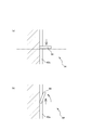
- FIG. , (B) when a transport apparatus having a gap in the transport direction on the downstream side or the upstream side, such as the transport direction conversion units 31 and 33, is used, FIG. , (B), it is desirable to provide the overturn suppressing part 29 in the adjacent position.
- the overturn suppression unit 29 is provided with a guide plate 29a that rises along the conveyor frame that forms the transport direction conversion units 31 and 33, and a guide piece 29b is provided on the guide plate 29a.
- the guide piece 29b is a piece-like member provided so as to extend in the lateral direction at a position on the upper side corresponding to the height of the tray T from the conveyance surface of the conveyance direction conversion units 31 and 33.
- the lifting and falling of the tray T that has reached the conveyance direction changing sections 31 and 33 can be regulated by the conveyance surface and the guide piece 29b. Thereby, it is possible to suppress the occurrence of the conveyance failure of the tray T due to the uneven load of the articles accommodated in the tray T.
- the upper side moving device 34 is connected to a lowering unit 50 of the completed container storage unit 38 described in detail later.
- the tray T conveyed by the upper side moving device 34 can be delivered to the complete container storage unit 38.
- the complete container storage unit 38 moves the tray T from the upper side to the lower side by the lowering unit 50. Therefore, the upper part of the complete container storage unit 38 connected to the upper side moving device 34 has a conveyance direction conversion unit 37 (third conveyance direction conversion unit) in which the conveyance direction of the tray T changes from the horizontal direction to the vertical direction. It becomes.
- the upper side moving device 34 is provided with a pushing mechanism 39 for pushing (pushing) the tray T from the upstream side in the carrying direction toward the carrying direction conversion unit 37.
- the push-in mechanism 39 may be anything as long as it can perform the operation of pushing in the tray T.
- the push-in mechanism 39 is as shown in FIG. Specifically, the pushing mechanism 39 includes a pushing piece 39a and a slide mechanism 39b that slides the pushing piece 39a in a direction in which the pushing piece 39a approaches and separates from the conveyance direction conversion unit 37.
- the pushing piece 39a is disposed at a substantially central portion in the width direction of the upper side moving device 34, and is urged so as to protrude upward from the conveying surface.
- the pushing piece 39a is pushed down when the tray T transported from the upstream side passes through the pushing piece 39a. However, when the tray T passes through, the pushing piece 39a returns to the state protruding upward. Therefore, after the tray T passes over the pushing piece 39a, the tray T can be pushed and moved by the pushing piece 39a by sliding the pushing piece 39a toward the transport direction changing portion 37 by the slide mechanism 39b.
- the elevating device 36 moves the tray T in the vertical direction between a lower side moving device 32 that forms a lower conveyance region and an upper side movement device 34 that forms an upper conveyance region.
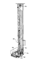
- the lifting device 36 may be any device, but in this embodiment, as shown in FIG. 6, the lifting device 36 has an introduction portion 42 on the lower end side and a discharge portion 44 on the upper end side.
- the lifting device 36 includes a lifting mechanism 46 (see FIG. 7) that moves up and down between the introduction portion 42 and the discharge portion 44.
- the introduction part 42 is a part into which the tray T conveyed by the lower side moving device 32 is introduced.
- the discharge unit 44 is a part that discharges the tray T from the lifting device 36 toward the upward movement device 34.
- the lifting mechanism 46 is a mechanism for moving the tray T introduced in the introducing portion 42 toward the discharging portion 44.
- the elevating device 36 can change the conveyance direction of the tray T from the horizontal direction to the vertical direction in the introduction unit 42, and can change the conveyance direction of the tray T from the vertical direction to the horizontal direction in the discharge unit 44.
- the lifting device 36 functions as a transport direction conversion unit 45 (first transport direction conversion unit) that can three-dimensionally change the transport direction of the tray T.
- the elevating device 36 has an introduction port 42a in a portion forming the introduction portion 42, and the tray T conveyed from the lower side moving device 32 via the introduction port 42a. Can accept. Further, the elevating device 36 has a discharge port 44a at a portion forming the discharge unit 44, and can discharge the tray T toward the upper side moving device 34 through the discharge port 44a.
- the elevating mechanism 46 has a mounting portion 46a, a horizontal operation portion 46b, a vertical operation portion 46c, and a detection portion 46d.
- a horizontal operation unit 46b and a detection unit 46d are mounted on the mounting unit 46a.
- the mounting portion 46a can be moved up and down by operating the up and down operation portion 46c.
- the elevating mechanism 46 can move up and down in a state where the tray T is placed on the horizontal operation unit 46b mounted on the mounting unit 46a.
- the horizontal operation unit 46b performs an operation of drawing the tray T introduced from the introduction port 42a into the mounting unit 46a and an operation of discharging the tray T from the mounting unit 46a.
- the horizontal operation unit 46b may be anything as long as it can pull in and pay out the tray T, such as a roller conveyor or a belt conveyor, but in this embodiment, a belt conveyor is adopted.
- the horizontal operation unit 46b can be operated while changing the feeding direction in the forward direction and the reverse direction by controlling the operation of the motor 46m.
- the horizontal operation part 46b is provided in the mounting part 46a. Therefore, the tray T can be pulled and mounted on the mounting portion 46a by operating the horizontal operation portion 46b in the forward direction. Further, by operating the horizontal operation unit 46b in the reverse direction, the tray T on the horizontal operation unit 46b can be discharged.
- the vertical operation part 46c is for operating the mounting part 46a in the vertical direction.
- the vertical movement part 46c may be anything as long as it can move the mounting part 46a up and down.
- the mounting portion 46 a is mounted on the belt 46 v that is wound around the pulleys 46 e and 46 f provided on the upper end side and the lower end side of the lifting device 36 as the vertical movement portion 46 c.
- the motor 46n is connected to one of the pulleys 46e and 46f (the pulley 4f in this embodiment).
- the vertical movement unit 46c can move the lifting device 36 in the vertical direction by operating the motor 46n and rotating the belt 46v between the pulleys 46e and 46f.
- the elevating device 36 can make the tray T acceptable by operating the up-and-down operation unit 46 c to bring the mounting unit 46 a to the introduction unit 42. Further, the lifting device 36 moves the tray T on the horizontal operation unit 46 b upward by operating the vertical operation unit 46 c to reach the discharge unit 44, and toward the upper side movement device 34. Can be discharged.
- the detection unit 46 d is for detecting the arrival of the tray T to the lifting device 36 that forms the transport direction conversion unit 45.
- the detection unit 46d is used in the introduction unit 42 to detect (determine) whether or not the tray T is normally disposed on the horizontal operation unit 46b.
- the state in which the tray T is normally disposed in the horizontal operation unit 46b means that even if the vertical operation unit 46c is operated, the tray T on the horizontal operation unit 46b moves smoothly without interfering with various places. It refers to the state where it is placed in a possible position.
- the detection unit 46d is mounted on the mounting unit 46a together with the horizontal operation unit 46b.
- the detection unit 46d may be any device that can detect the arrival of the tray T to the lifting device 36, such as a photoelectric sensor.
- the detection unit 46d includes the first detection device 46g and the second detection device 46h so as to be able to determine whether or not the tray T is normally disposed. It is supposed to be.
- the first detection device 46g and the second detection device 46h are sensors that transmit an on-state signal when an article is detected.
- the first detection device 46g is a sensor that detects the presence or absence of an article on the downstream side in the transport direction of the tray T that arrives at the introduction unit 42.
- the first detection device 46g is provided at a position downstream in the transport direction by the transport device that forms the horizontal operation unit 46b.
- the first detection device 46g is provided at a position opposite to the introduction port 42a.
- the second detection device 46h is a sensor that detects the presence or absence of an article on the upstream side in the transport direction from the first detection device 46g.
- the second detection device 46h is provided at a position upstream in the transport direction by the transport device forming the horizontal operation unit 46b.
- the second detection device 46h is provided at a position on the introduction port 42a side with respect to the first detection device 46g. More specifically, the second detection device 46h is provided at a position away from the first detection device 46g on the upstream side by the size of the tray T or more.
- the interval between the first detection device 46g and the second detection device 46h is The length is longer than the length of the tray T.
- the interval between the first detection device 46g and the second detection device 46h is the tray
- the width is preferably equal to or greater than the width of T.
- the first detection device 46g and the second detection device 46h each detect an article by irradiating the tray T with light from the side.
- the four side surfaces of the tray T are provided with the light-transmitting openings S (light-transmitting portions), and the light passes therethrough and accurately detects the presence of the tray T. It may not be possible. Therefore, in the present embodiment, as indicated by arrows in FIG. 9, the first detection device 46g and the second detection device 46h are arranged so that the optical axis is directed obliquely downward.
- the optical axis is such that light (detection light) emitted from the first detection device 46g and the second detection device 46h can be projected through the opening S toward the bottom surface of the tray T with no light passing portion or few. It is installed in the state that adjusted the direction of
- the tray T When the tray T is normally disposed on the horizontal operation unit 46b, the article (tray T) is detected by the first detection device 46g, and the article (tray T) is not detected by the second detection device 46h. In contrast to this, the medicine falls to a position adjacent to the downstream side in the transport direction with respect to the tray T that has reached the horizontal operation unit 46b, and the tray T is not normally disposed on the horizontal operation unit 46b. Then, not only the article is detected by the first detection device 46g but also the article is detected by the second detection device 46h. That is, when both the first detection device 46g and the second detection device 46h detect the article, the tray T protrudes from the normal position to the upstream side in the conveyance direction (second detection device 46h side). It is assumed that
- the complete container storage unit 38 stores, as a complete container, a container assigned to a prescription in which preparation of medicines to be arranged in the tray T has been completed by the dispensing by the medicine dispensing apparatus 20.
- the complete container storage unit 38 can be installed, for example, near the window of the dispensing room.
- the complete container storage unit 38 is connected to the upper side moving device 34 in the upper part. Therefore, as shown in FIG. 1 and FIG. 10, the upper end side of the complete container storage unit 38 is formed with a portion that becomes a conveyance direction conversion unit 37 in which the conveyance direction of the tray T changes from the horizontal direction to the vertical direction. Yes.
- the transport direction changing portion 37 is provided with a step 37 b so that the transport path is lower than the upstream side (the transport surface of the upper moving device 34). For this reason, when the tray T reaches the transport direction changing portion 37, the tray T is lowered by the level difference 37b. Further, the conveyance direction converting unit 37 is provided with a rebound suppressing unit 37a.
- the rebound suppressing unit 37a is for suppressing the tray T pushed into the transport direction converting unit 37 by the pushing mechanism 39 described above from rebounding upstream in the transport direction.
- the rebound suppressing portion 37a may be any member as long as it can perform its function, but is configured by a piece-like member in the present embodiment.
- the rebound suppressing portion 37a is provided so as to arrive at a position adjacent to the upstream side in the transport direction with respect to the flange T2 in a state where the tray T is lowered by the step 37b of the transport direction converting portion 37. Therefore, when the tray T is pushed by the push-in mechanism 39 and reaches the transport direction changing portion 37, the hook T2 interferes with the rebound suppressing portion 37a and cannot be bounced even if the tray T tries to bounce upstream. Thereby, the tray T can be fastened at a predetermined transport position.
- the complete container storage unit 38 includes a lowering unit 50 below the transport direction changing unit 37 described above.
- the lowering unit 50 has a container moving space 54 formed so as to communicate upward in the housing 52 of the completed container storage unit 38.
- the lowering unit 50 can be moved from the upper side to the lower side while supporting the tray T in the container moving space 54.
- the lowering unit 50 is connected to the above-described upper moving device 34 on the upper end side. Therefore, the lowering unit 50 can receive the tray T conveyed by the upper side moving device 34 and store it while lowering the tray T to a position where a pharmacist or the like can easily take it in the dispensing chamber.
- the lowering unit 50 can take out the tray T from an opening provided in a pair of the first side surface 52 a and the second side surface 52 b facing each other forming the housing 52. Therefore, by arranging an operator such as a pharmacist on the first side surface 52a side and the second side surface 52b side, the complete container storage unit 38 can be used in a usage method shared by both workers.
- the lowering unit 50 has two types of claws, that is, an operating claw 56 and a moving claw 58, and an operating claw operating mechanism 60 and a moving claw operating mechanism 62 for operating these claws.
- the operating claw 56 is a claw capable of switching the protruding state between a state protruding from the side toward the container moving space 54 and a state retracted from the container moving space 54.
- a plurality of operating claws 56 are provided at predetermined positions in the vertical direction.
- the operating claw operating mechanism 60 may be anything as long as it can operate the operating claw 56, but in this embodiment, the operating claw 56 includes an actuator such as a motor, and the operating claw 56 is interlocked with the operation of the actuator. Can be operated.
- the moving claw 58 is a claw that is movable in the vertical direction while protruding from the side toward the container moving space 54.
- a plurality of moving claws 58 are provided so as to be arranged corresponding to each of the operating claws 56.
- the moving claw 58 is disposed at a position adjacent to the left and right with respect to one operating claw 56.
- the moving claw actuating mechanism 62 may be anything as long as it can move the moving claw 58 in the vertical direction.
- the moving claw actuating mechanism 62 the moving claw 58 is set at a predetermined interval with respect to the belts 62c and 62d wound around the pulleys 62a and 62b provided on the upper end side and the lower end side of the lowering unit 50.
- Each of the pulleys 62a and 62b is attached to each other, and the power output from the motor 62e can be transmitted to one of the pulleys 62a and 62b (the pulley 62a in this embodiment).
- the lowering unit 50 can lower the tray T by moving the moving claw 58 downward while keeping the operating claw 56 retracted from the container moving space 54. Further, the tray T can be supported from below by the operating claw 56 and the moving claw 58 in a state where the moving claw 58 has arrived at a position corresponding to the operating claw 56. Specifically, the lowering unit 50 has the moving claw 58 in a state where the moving claw 58 has arrived at a position corresponding to the working claw 56 projected from the side (supported state) toward the container moving space 54. 56 and the moving claw 58 can support the tray T from below at the flange portion T2.
- the lowering unit 50 includes a first side sensor 64 and a second side sensor 66 in addition to the operating claws 56 and the moving claws 58 described above.
- the 1st side sensor 64 and the 2nd side sensor 66 are sensors which detect the tray T which came out from the container moving space 54 to the 1st side surface 52a side or the 2nd side surface 52b side, respectively.
- the incomplete container storage unit 40 is for storing, as an incomplete container, the tray T assigned to a prescription in which preparation of medicines to be arranged in the tray T is insufficient for the medicine dispensing apparatus 20 to dispense.
- the incomplete container storage unit 40 may be anything as long as it can store incomplete containers, but may be as shown in FIG. 13, for example.
- the incomplete container storage unit 40 of the present embodiment includes a lifter 70 that can lift the tray T.
- the uncompleted container storage unit 40 can lift and store a plurality of trays T related to the uncompleted prescription with the lifter 70 so as to be in a state of being vertically aligned.
- the lifter 70 has a pair of claw members 72, 72 provided along the left and right side surfaces of the incomplete container storage unit 40.
- the lifter 70 can support the tray T substantially horizontally by supporting the flange portion T2 of the tray T from below by the claw members 72, 72.
- a moving mechanism (not shown) for moving the claw members 72, 72 upward is provided. Therefore, by moving the pair of claw members 72 and 72 supporting the tray T from both sides upward, the tray T can be moved upward while maintaining substantially horizontal.
- the control unit 100 performs operation control of the medicine dispensing device 20 and the transport system 30 that constitute the medicine dispensing system 10.
- the control unit 100 includes a conveyance direction conversion unit 45 (first conveyance direction conversion unit), a conveyance direction conversion unit 33 (second conveyance direction conversion unit), and a conveyance direction conversion unit 37 (third conveyance direction conversion unit). And the operation control relating to the completed container storage unit 38 and the incomplete container storage unit 40.
- operation control of each unit performed by the control unit 100 will be described in detail with reference to the drawings.
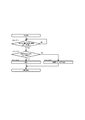
- Step 1-1 the control unit 100 determines whether there is a tray T to be moved toward the upper side moving device 34. As a result, if it is determined that there is a tray T to be moved toward the upper side moving device 34, the control flow proceeds to step 1-2.
- Step 1-2 the control unit 100 moves the mounting portion 46a toward the introduction portion 42 in the lifting device 36. Thereby, the horizontal operation
- step 1-3 the control unit 100 operates the lower side moving device 32. Accordingly, the tray T to be moved toward the upper side moving device 34. (Complete tray) is moved to the lifting device 36 side.
- Step 1-4 the control unit 100 determines whether or not the tray T (complete tray) has reached the inlet 42a of the lifting device 36. Whether or not the tray T has reached the introduction port 42a can be determined based on detection information such as, for example, the second detection device 46h or a sensor provided separately. Here, if it is determined that the tray T has reached the inlet 42a, the control flow proceeds to step 1-5.
- Step 1-5) the control unit 100 operates the horizontal operation unit 46b that is in standby by the introduction unit 42 of the lifting device 36. As a result, the tray T is pulled onto the horizontal operation unit 46b. Thereafter, the control flow proceeds to step 1-6.
- Step 1-6 the control unit 100 confirms whether or not the detection signal of the first detection device 46g has been turned on.
- the control flow proceeds to step 1-7.
- step 1-7 the control unit 100 stops the operation of the horizontal operation unit 46b. Thereby, the operation of pulling in the tray T is completed. Thereafter, the control flow proceeds to step 1-8.
- step 1-8 the control unit 100 confirms whether or not the detection signal of the second detection device 46h is in an on state.
- the tray T is detected by the first detection device 46g, but the tray T is not detected by the second detection device 46h. become.
- the detection signal of the first detection device 46g is in an on state because the contents (conveyed object) of the tray T have fallen to the tip of the tray T or there is another obstacle. It is assumed that the tray T is at a position shifted to the introduction port 42a side by the amount of fallen objects or the like. Therefore, when the detection signal of the second detection device 46h is in the on state in step 1-8, it is considered that the tray T has not been pulled to a normal position due to a fallen object or the like at the tip of the tray T. It is done.
- step 1-8 when the detection signal of the second detection device 46h is in the on state in step 1-8, the control unit 100 determines that the tray T has not reached the normal position. The control flow proceeds to step 1-11. On the other hand, if the detection signal of the second detection device 46h is in the OFF state in step 1-8, it is determined by the control unit 100 that the tray T has been pulled to the normal position, and the control flow is step 1-. Proceed to 9.
- Step 1-9 the control unit 100 operates the up / down operation unit 46c to cause the mounting unit 46a to reach the discharge unit 44. Thereby, the horizontal operation
- Step 1-10 the control unit 100 operates the horizontal operation unit 46b in the direction opposite to that during the pulling operation. Thereby, the tray T is discharged from the discharge port 44a toward the upper side moving device 34, and a series of control flows is completed.
- Step 1-11 the control unit 100 performs a process of notifying that the tray T is in a state where it cannot reach the normal position due to the influence of a falling object or the like. Specifically, the control unit 100 operates such that a notification device such as a buzzer, a speaker, or a display provided separately notifies the user by voice or display, or notifies by using an operation panel provided along with the control unit 100. Control is made. Thereby, a series of control flow is completed.
- a notification device such as a buzzer, a speaker, or a display provided separately notifies the user by voice or display, or notifies by using an operation panel provided along with the control unit 100. Control is made. Thereby, a series of control flow is completed.
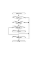
- Step 2-1 the control unit 100 checks whether or not the tray T has reached the transport direction changing unit 33.
- the arrival of the tray T can be confirmed by a sensor or the like provided in the transport direction conversion unit 33. If the arrival of the tray T is confirmed in step 2-1, the control flow proceeds to step 2-2.
- Step 2-2 the control unit 100 confirms whether or not the presence of the tray T is detected by the container detection sensor 35.
- the container detection sensor 35 is a sensor that can detect whether or not the tray T exists in a state where the tray T protrudes to a region exceeding the width direction of the conveyance path on the downstream side in the conveyance direction conversion unit 33. Therefore, in step 2-2, it is confirmed whether or not the presence of the tray T is detected by the container detection sensor 35. If it is detected, the control flow proceeds to step 2-3. The process of advancing the control flow to step 2-4 is performed.
- Step 2-3 As described above, when the presence of the tray T is detected by the container detection sensor 35 in step 2-2, the posture of the tray T is not suitable for transporting downstream of the transport direction converting unit 33. Is in a state. Therefore, in step 2-3, the control unit 100 performs a process of notifying that the tray T cannot be smoothly conveyed toward the downstream side. Specifically, the control unit 100 operates such that a notification device such as a buzzer, a speaker, or a display provided separately notifies the user by voice or display, or notifies by using an operation panel provided along with the control unit 100. Control is made. Thereby, a series of control flow is completed.
- a notification device such as a buzzer, a speaker, or a display provided separately notifies the user by voice or display, or notifies by using an operation panel provided along with the control unit 100. Control is made. Thereby, a series of control flow is completed.
- Step 2-4 As described above, when the presence of the tray T is not detected by the container detection sensor 35 in step 2-2, there is no problem even if the posture of the tray T is transported downstream from the transport direction converting unit 33. It is assumed that it is in a state. Therefore, in step 2-4, operation control is performed so as to perform an operation of feeding the tray T from the transport direction changing unit 33 toward the downstream transport path. Thereby, a series of operation control is completed.
- Step 3-1) the control unit 100 determines whether or not the tray T can be moved to the transport direction changing unit 37. The determination as to whether or not the tray T can be moved is performed by a sensor provided in the transport direction conversion unit 37 as a determination condition that no other tray T exists in the transport direction conversion unit 37. If it is determined in step 3-1 that the tray T can be transported, the control flow proceeds to step 3-2.
- Step 3-2 control for moving the tray T with respect to the transport direction changing portion 37 is performed. Specifically, operation control by the control unit 100 is performed so that the conveyor on the upstream side operates. As a result, the tray T is transported toward the transport direction changing portion 37. Further, when the tray T reaches the position where the pushing mechanism 39 is provided, the pushing mechanism 39 is operated. As a result, the tray T is pushed toward the transport direction changing portion 37. Thereafter, the control flow proceeds to Step 3-3.
- step 3-3 the control unit 100 determines whether or not the tray T has reached the transport direction changing unit 37.
- the arrival of the tray T can be confirmed by a sensor or the like provided in the transport direction conversion unit 37. If the arrival of the tray T is confirmed in step 3-3, the control flow proceeds to step 3-4.
- step 3-4 it is determined whether or not the tray T reaching the transport direction changing section 37 can be moved with respect to the completed container storage section 38 connected to the transport direction changing section 37. This is performed by the control unit 100. Specifically, it is confirmed whether or not there is an empty space in the complete container storage unit 38 where the tray T can be stored. Here, if it is determined that the tray T cannot be moved to the complete container storage unit 38 side, the control flow enters a standby state in step 3-4 until the tray T can be moved. On the other hand, if it is determined that the container can be moved to the complete container storage unit 38 side, the control flow proceeds to step 3-5.
- Step 3-5 it is confirmed whether or not the tray T protrudes from the container moving space 54 only on the first side surface 52a side or the second side surface 52b side (tray protruding state). 100. Whether or not the tray is protruding can be determined by an appropriate method, but in the present embodiment, it is determined based on detection signals output from the first side sensor 64 and the second side sensor 66. Is done. Specifically, the tray is in a protruding state on condition that a detection signal indicating that the tray T is detected is output from only one of the first side sensor 64 and the second side sensor 66. Is determined by the control unit 100.
- step 3-6 the control flow proceeds to step 3-6 to prohibit the warning and the operation of the lowering unit 50 to that effect.
- the control flow is advanced to step 3-7.
- Step 3-6 the control unit 100 performs a warning that the tray is protruding and a process for prohibiting the operation of the lowering unit 50. Thereafter, the control flow is returned to step 3-5.
- Step 3--7 the control unit 100 determines whether or not there is a plurality of operating claws 56 that are arranged in the vertical direction with a predetermined interval and that cannot be retracted from the container moving space 54. Confirm. Whether each operating claw 56 can be retracted is determined by an appropriate method such as a method for determining based on an output signal from a separately provided sensor or the like, or a method for determining based on information input by a user. It can be. In the present embodiment, it is confirmed whether or not the retracting operation is possible by actually operating each operating claw 56. If it is determined in step 3-7 that there is an operating claw 56 that cannot be retracted, the control flow proceeds to step 3-8, and it is determined that there is no operating claw 56 that cannot be retracted. The control flow proceeds to step 3-9.
- Step 3-8) the control unit 100 performs a process (movable range limiting process) for limiting the range in which the tray T can be lowered (the range in which the tray T can be lowered) in the complete container storage unit 38.
- the descendable range is limited to the position where the operating claw 56 determined to be unretractable in step 3-5 is provided, and the range above the region. Thereafter, the control flow proceeds to step 3-9.
- step 3-9 the control unit 100 operates the lowering unit 50, and sequentially feeds the tray T to the position of the operation claw 56 that is confirmed to be empty in step 3-8.
- the tray T is sequentially lowered downward (loading processing).
- the control unit 100 performs the loading process as described in detail later with reference to FIG. Thereby, a series of control flow is completed.
- the tray T (complete tray) is moved up and down the moving device 36 and the upper moving device 34 on condition that the lifting device 36, the upper side moving device 34, and the completed container storage unit 38 are all usable. It can be transferred by a route that passes through and stored in the complete container storage unit 38. However, when any one of the elevating device 36, the upper side moving device 34, and the complete container storage unit 38 becomes unusable, the tray T is transferred to the complete container storage unit 38 to be supplemented. I can't do that.
- the lifting / lowering device 36, the upper side moving device 34, and the complete container storage unit 38 are partially or completely unusable.
- a backup operation using the complete container storage unit 40 for storing the tray T can be executed.
- the backup operation by the incomplete container storage unit 40 will be described in detail with reference to FIG.
- Step 4-1 the control unit 100 determines whether or not a series of processes (complete container transport storage process) until the tray T (complete tray) is transported to the complete container storage unit 38 and stored is possible. Confirm. As a specific example, in this embodiment, it is confirmed whether or not all of the elevating device 36, the upper side moving device 34, and the complete container storage unit 38 are in a usable state. As a result, when the complete container transport and storage process is impossible (in this embodiment, it is confirmed that a part or all of the lifting device 36, the upper side moving device 34, and the complete container storage unit 38 are unusable. The control flow proceeds to step 4-2.
- Step 4-2 the control unit 100 performs control to move the tray T (completed container) to the incomplete container storage unit 40 by the lower side moving device 32. Thereafter, the control flow proceeds to step 4-3.
- step 4-3 the control unit 100 activates the incomplete container storage unit 40 to thereby store the tray T (completed container) that should be stored in the complete container storage unit 38. 40 is stored. Thereby, a series of control flow is completed.
- the transport system 30 determines whether or not the tray T is normally disposed in the transport direction conversion unit 45 . Judgment based on Accordingly, the transport system 30 accurately grasps whether or not the tray T is normally disposed in the transport direction changing unit 45, and the transport failure of the tray T, the failure of the transport system 30, or the damage of the tray T is detected. Etc. can be suppressed.
- the first detection device 46g and the second detection device 46 h have their optical axes directed so that they can project toward the bottom surface T ⁇ b> 1 of the tray T through the opening S provided in the tray T. It is installed at. Therefore, even if the tray T provided with the opening S is used, the tray T can be accurately detected by the first detection device 46g and the second detection device 46h.
- the first detection device 46g and the second detection device 46h are exemplified by the configuration in which the optical axis is directed in the above-described direction, but the present invention is not limited to this. Specifically, one or both of the first detection device 46g and the second detection device 46h may be installed under different installation conditions from those described above.
- first detection device 46g and the second detection device 46h may be configured by other than photoelectric sensors, or the tray T may be a device that does not have a light-transmitting portion such as the opening S. You may eliminate the concern of poor detection due to the passage of light.
- the tray T it is determined whether or not the tray T is present at the normal position in the transport direction conversion unit 45 in a portion where the transport direction of the tray T changes three-dimensionally (three-dimensionally). It is determined whether or not the tray T can be moved up and down thereafter. Therefore, in the transport system 30, even when the tray T is transported along a transport path that involves the vertical movement of the tray T, the tray T is transported stably while taking into consideration that the tray T does not fall or the like. be able to.
- the tray T is in the normal position using the first detection device 46g and the second detection device 46h in the conveyance direction conversion unit 45 at a portion where the conveyance direction of the tray T changes three-dimensionally (three-dimensionally).
- the present invention is not limited to this. Specifically, whether or not the tray T has reached the normal position by the same configuration and control even in a two-dimensionally changing portion where the transport direction of the tray T does not change in the height direction. It may be determined.
- a transport direction conversion unit 33 that changes in a direction in which the transport direction of the tray T intersects in the middle of the transport path is provided. Further, a container detection sensor 35 is provided in the transport direction conversion unit 33 to detect whether or not the tray T that has reached the transport direction conversion unit 33 is tilted or the like and protrudes to a region exceeding the width of the transport path on the downstream side. Thus, it is determined whether or not the tray T can be moved from the transport direction conversion unit 33 toward the downstream side without any problem. Therefore, in the transport system 30, it is possible to prevent the transport failure of the tray T from occurring when the transport direction changes in the transport direction conversion unit 33.
- the transport direction conversion unit 33 and the like are more upstream than the upstream side.
- the portion on the downstream side where the width of the transport path is reduced is illustrated, but the present invention is not limited to this.
- the width of the transport path is substantially the same on the upstream side and the downstream side with respect to the position where the transport direction changes, or on the downstream side of the upstream side with respect to the position where the transport direction changes.
- a similar one to the container detection sensor 35 may be provided in the same manner as the transport direction converting unit 33 to perform the same control.
- the conveyance direction conversion unit 33 and the upstream side in the conveyance direction are typical examples.
- the tray T is transported in the length direction and the tray T is transported in the width direction on the downstream side in the transport direction with respect to the transport direction conversion unit 33.
- the present invention is not limited to this.
- the part opposite to that described above that is, the part that changes the transport direction of the tray T transported in the width direction from the upstream side in the length direction may be configured similarly to the transport direction converting unit 33 described above. .
- the transport system 30 of the present embodiment in addition to the pushing mechanism 39 for pushing the tray T toward the transport direction conversion unit 37, the rebound of the tray T that has reached the transport direction conversion unit 37 to the upstream side in the transport direction is suppressed.
- a rebound suppressing portion 37a is provided. Therefore, it is possible to suppress the tray T from bouncing back to the upstream side while reliably pushing the tray T toward the transport direction conversion unit 37 by the pushing mechanism 39.
- the transport direction conversion unit 37 further suppresses the rebound of the tray T to the upstream side by providing the step 37 b so as to be lower than the upstream side of the transport path.
- the transport direction conversion unit 37 is provided with the step 37b and the bounce suppression unit 37a in consideration of the bounce of the tray T to the upstream side due to the external force acting on the tray T by the push mechanism 39.
- the present invention is not limited to this. Specifically, instead of providing the bounce suppressing portion 37a, the bounce of the tray T may be suppressed by other measures. Further, the tray T is transported to the transport direction conversion unit 37 by a conveyor, and the tray T is fed by various methods such as accelerating in front of the transport direction conversion unit 37, thereby preventing the tray T from being rebounded. May be provided.
- the entire lowering unit 50 is not disabled, but the operating pawl 56 that has become unable to retract, and The tray T is supported while being limited to the range of the operating claw 56 on the upper side than this, and is moved downward. Therefore, in the transport system 30, even if a part of the operating claw 56 cannot be retracted, the lowering unit 50 can be effectively used as much as possible within the usable range.
- the vertical movement of the tray T is performed on the condition that only one of the first side sensor 64 and the second side sensor 66 is detected in the lowering unit 50. It is forbidden. By performing such control, it is possible to prevent the tray T from being moved up and down in an unstable state in which the lowering unit 50 is biased toward the first side surface 52a or the second side surface 52b.
- the tray T that has been transported via the upper side moving device 34 disposed on the ceiling side is moved to the completed container storage unit 38 via the transport direction changing unit 37, and the completion is completed.
- the container storage unit 38 can be lowered toward the floor.
- the transport state of the tray T can be managed based on the read information.
- the conveyance of the tray T on the upper side moving device 34 is stopped.
- the drug dispensing system 10 of the present embodiment includes the transport system 30 as described above. Therefore, the medicine dispensed from the medicine dispensing apparatus 20 to the tray T can be accurately conveyed to a predetermined position. Thereby, troubles, such as a stop of the medicine dispensing system 10 due to the conveyance failure of the tray T, can be suppressed to the minimum, and the efficiency of the dispensing operation can be contributed.
- the completion tray can reach the completion container storage unit 38 via the elevating device 36 and the upper side movement device 34 to be stored. Therefore, the path for transporting the complete tray can be arranged on the ceiling side of the dispensing chamber or the like, and the space can be used effectively.
- the ceiling side space such as the dispensing chamber is effectively used for moving the complete tray and the incomplete tray is moved in the floor side space is shown, but the present invention is not limited thereto. It is not something. Specifically, a configuration that effectively uses the space on the ceiling side of the dispensing room, etc. not only for moving the completed tray, but also for moving the unfinished tray, and for moving the space on the ceiling side for the unfinished tray.
- It may be configured to use and move the complete tray in the space on the floor side. From the viewpoint of effective use of the indoor space, it is desirable to move one or both of the completed tray and the unfinished tray to the space on the ceiling side, but both the completed tray and the unfinished tray are moved on the floor side. It is good also as a structure to which it moves.
- the completion tray is moved downward on condition that the lifting device 36, the upper side movement device 34, and the completion container storage unit 38 used for conveying the completion tray become unusable.
- the uncompleted container storage unit 40 can be reached and stored via the device 32.
- the incomplete container storage unit 40 can be used as a backup when the elevating device 36, the upper movement device 34, and the complete container storage unit 38 become unusable. . Therefore, according to the present embodiment, even when the elevating device 36 and the upper side moving device 34 become unusable, it is possible to minimize the decrease in the efficiency of the dispensing operation due to the entire medicine dispensing system 10 being stopped or the like. Can be suppressed.
- the incomplete container storage unit 40 is used as a backup when the elevating device 36, the upper side moving device 34, and the complete container storage unit 38 become unusable.
- the invention is not limited to this. Specifically, even when the elevating device 36, the upper side moving device 34, and the completed container storage unit 38 become unusable, the uncompleted container storage unit 40 is not used as a backup, and the completed tray can be stored. A separate backup storage may be provided.
- a plurality of container stopping positions A for stopping the tray T are provided in the vertical direction.
- seven container stop positions A1 to A7 are provided in the vertical direction.
- Each container stop position A is provided with an operating claw 56 and a moving claw 58.
- the tray T can be stopped at each container stop position A by supporting the flange portion T ⁇ b> 2 of the tray T by the operation claw 56. Further, in the complete container storage unit 38, the tray T can be moved in the vertical direction with the moving claw 58 supporting the flange portion T2 of the tray T from below.
- the lowering unit 50 has a pair of operating claws 56 for each container stop position A. Further, the lowering unit 50 has a plurality of moving claws 58 provided so as to be movable in the vertical direction on the side of the operating claws 56. The pair of operating claws 56 are arranged so as to face each other through the container moving space 54. The moving claws 58 are also provided so as to face each other through the container moving space 54 in the same manner as the operating claws 56.
- the operation claw 56 is operation-controlled by the control unit 100 and can be switched between a state protruding from the side toward the container moving space 54 (supportable state) and a state retracted from the container moving space 54 (retracted state). ing. More specifically, as shown in FIG. 20, the operating claw 56 can swing with one end as a swing fulcrum. The operating claw 56 has a posture in which the other end, which is a free end, protrudes from the side toward the container moving space 54 (see FIG. 20A), and the other end is located above and retracts from the container moving space 54. It is possible to switch to the posture (see FIG. 20B). By such an operation, the operating claw 56 can be switched between a supportable state and a retracted state.
- the tray C can be stopped at the container stop position A by making the operating claw 56 supportable (stop state).
- the collar portion T2 of the tray T is supported not only by the operating claw 56 but also by the moving claw 58 in the stationary state.
- the moving claw 58 is pressed from above by the flange T2 in the stationary state, and supports the tray T while maintaining a substantially horizontal posture.
- the moving claw 58 is provided on both sides of the one operating claw 56.
- the moving claw 58 is attached to the belts 62c and 62d so as to freely swing up to a predetermined angle. More specifically, as shown in FIG. 21A, when a load is applied from above, the moving claw 58 protrudes from the side toward the container moving space 54 and maintains a substantially horizontal posture. Therefore, the tray T can be moved in the container moving space 54 by moving the moving claw 58 in the vertical direction with the flange portion T2 of the tray T mounted on the moving claw 58.
- the moving claw 58 swings upward with the portions attached to the belts 62c and 62d as swinging fulcrums. Therefore, even if there is a tray T that is still in the container stop position A (illustrated as the container stop position A2 in FIG. 22) as shown in FIG.
- the moving claw 58 can be moved from the upper side to the lower side of the tray T. More specifically, for example, when the tray is stopped at the container stop position A2 as shown in FIG.
- the operating claw 56 at the container stop position A2 protrudes toward the container moving space 54 (a)
- the moving claw 58 moves from above the container stop position A2 toward the flange T2 of the tray T.
- the moving claw 58 can be retracted by swinging the free end side upward by applying a pushing force from below. Further, as shown in FIG. 22B, when the moving claw 58 that has moved downward with the movement of the belt 62c comes into contact with the flange T2 of the tray T that is stopped at the container stopping position A2, the moving claw is moved. A pushing force acts on 58 from below. As a result, the moving claw 58 is pushed upward by the collar portion T ⁇ b> 2 so as to be retracted from the container moving space 54. Therefore, even if there is a tray T that remains in the stopped state at the container stop position A, the presence of the tray T that has been stopped does not become an obstacle, and the moving claw 58 can be moved. .
- the moving claw 58 When the moving claw 58 passes through the position of the tray T in the stationary state and moves further downward, the moving claw 58 is restored to a state protruding from the side toward the container moving space 54 and returns to a state in which the tray T can be supported. .
- the transport system 30 can operate the lowering unit 50 by the control unit 100 to sequentially lower (stack) one or more trays T. Further, in the loading operation, the transport system 30 is placed in a stopped state among the container stop positions A1 to A7 and a state where the operation claw 56 does not support the tray T (empty state). When one or more trays T are present, at least one tray T can be lowered and placed in another container stop position A while maintaining the placement of one or more trays T with respect to the container stop position A. Has been. Further, in the loading operation, the transport system 30 is configured when there is a container stop position A that is vacant between two or more container stop positions A that are stopped among the container stop positions A1 to A7. Then, the tray T can be lowered and placed (filled) with respect to one or more container stop positions A that are in an empty state.
- the lowering unit 50 performs the stacking operation on the basis of an arbitrary position among the container stop positions A (the container stop positions A1 to A7 in the present embodiment) provided in the vertical direction of the container moving space 54.
- the tray T can be moved so that the tray T is arranged in the direction or in the downward direction. That is, the lowering unit 50 can move the tray T so that the tray T is placed at each container stop position A provided upward or downward from the reference container stop position A. .
- the lowering unit 50 uses the container stop position A (for example, the container stop position A1) above the container moving space 54 among the container stop positions A1 to A7 as a reference, An operation (hereinafter also referred to as “upper reference stacking operation”) of lowering the tray T so that the trays T are packed and arranged in the downward direction in order from the container stop position A1 can be performed.
- the lowering unit 50 is configured so that the trays are sequentially moved upward from the container stop position A7 with reference to the container stop position A (for example, the container stop position A7) on the lower side of the container moving space 54.
- An operation of lowering the tray T so that T is arranged in a packed manner (hereinafter also referred to as “upper reference stacking operation”) can be performed.
- FIG. 23 is a conceptual diagram showing an example of the arrangement of the trays T when the trays T are stacked on the upper reference.
- the control unit 100 When loading and unloading the trays T based on the upper reference, the control unit 100 performs operation control for lowering the trays T so that the trays T are arranged sequentially from the container stop position A1.
- the control unit 100 Control is performed to place the tray T (hereinafter also referred to as “new tray T”) that has reached the transport direction conversion unit 37 at the container stop position A1 located at the uppermost stage.
- new tray T the tray T
- FIG. 23 (a-2) when a new tray T arrives at the transport direction changing section 37 in a state where the tray T is disposed at the container stop position A1, the control section 100 The tray T arranged at the stop position A1 is sequentially fed to the container stop position A2, and the operation control for transporting a new tray T to the container stop position A1 is performed.
- FIGS. 23 (b-1) and (b-2) in the state where the plurality of trays T are arranged on the upper reference, one or more trays T are extracted from the completed container storage unit 38. In the case of a failure, no padding operation is performed. More specifically, as shown in FIG. 23 (b-1), from the state in which the tray T is disposed at each of the container stop positions A1 to A4, the container stop position as shown in FIG. 23 (b-2). When the trays T arranged at A2 and A3 are extracted, the arrangement is maintained without lowering the trays T arranged at the container stopping positions A1 and A4.
- FIGS. 23 (c-1) and (c-2) one or more container stop positions A that are vacant exist between two or more container stop positions A that are stopped.
- a stuffing operation is performed. More specifically, in the case where there are container stop positions A2 and A3 that are vacant between the container stop position A1 and the container stop position A4 that have been stopped (see FIG. 23 (c-1)),
- the tray T arranged at the container stopping position A1 is moved to the container stopping position A2 while maintaining the arrangement of the tray T arranged at the container stopping position A4. Then, the new tray T is transported to the container stop position A1 (see FIG. 23 (c-2)).
- the lowering unit 50 can lower the tray T so that the tray T is arranged in the upper position as an upper reference.
- FIG. 24 is a conceptual diagram showing an example of the arrangement of the trays T when the trays T are stacked on the lower reference.
- the control unit 100 When loading and unloading the trays T based on the lower reference, the control unit 100 performs operation control for lowering the trays T so that the trays T are arranged sequentially from the container stop position A7.
- the control section 100 When a new tray T arrives at the transport direction changing section 37 in a state where no tray T exists at any of the container stopping positions A1 to A7, the control section 100 Performs control to place a new tray T at the container stop position A7 located at the lowest level. As shown in FIG. 24 (a-2), when a new tray T arrives at the transport direction changing section 37 in a state where the tray T is arranged at the container stop position A7, the control section 100 Operation control for transporting a new tray T to the container stop position A6 while maintaining the position of the tray T placed at the container stop position A7 so that the new tray T is arranged below the container moving space 54. Do.
- the container stopping positions A5 and A6 are moved as shown in FIG. 24 (b-2).
- an automatic stuffing operation is performed.
- the control unit 100 maintains the arrangement of the tray T arranged in the container stop position A7 so that the tray T is arranged in the empty container stop positions A5 and A6, while maintaining the arrangement of the tray T in the container stop position A4.
- Operation control is performed to lower the arranged tray T to the container stop position A6 that has become empty (see FIG. 24B-3).
- the filling operation is performed by satisfying a predetermined condition.
- the control unit 100 is provided that one or more container stop positions that are vacant exist between two or more container stop positions A that are stopped among the container stop positions A1 to A7. As shown in FIG.
- the transport direction When a new tray T arrives at the conversion unit 37, a stuffing operation is performed.
- the control unit 100 performs operation control to lower the tray T stopped at the container stop position A4 while maintaining the arrangement of the tray T with respect to the container stop position A7.
- the operation control for transporting the new tray T that has reached the transport direction changing unit 37 to the container stop position A5 is performed. Is performed (see FIG. 24C-3).
- FIG. 25 shows a subroutine of a stacking process in the transport control of the tray T in the transport direction changing unit 37 and the completed container storage unit 38 of FIG.
- Step 4-1) the control unit 100 performs a process of determining whether or not the upper reference stacking is set. Specifically, the control unit 100 performs a process of determining whether or not the lowering (upper reference unloading) with respect to the upper side of the container moving space 54 is set. It should be noted that whether the upper standard is to be lowered or the lower standard is to be lowered can be set by the user's selection. If it is determined in step 4-1 that the upper standard stacking is set, the control flow is advanced to step 4-2, and it is determined that the upper reference stacking is not set. If so, a process for advancing the control flow to step 4-3 is performed.
- Step 4-2 the control unit 100 performs an upper reference stacking process, which will be described in detail later with reference to FIG.
- the control unit 100 performs operation control such as an upper reference progressive process.
- step 4-3 the control unit 100 performs a lower reference loading process, which will be described in detail later with reference to FIG. In the lower reference stacking process, the control unit 100 performs operation control such as a lower reference progressive process. When the process of step 4-3 is completed, a series of control flows is completed.
- FIG. 26 is a diagram illustrating a subroutine of the upper reference stacking process.
- Step 5-1) the control unit 100 determines which container stop position A is empty within the range of the container stop positions A that are allowed to be lowered among the container stop positions A1 to A7. I do. Specifically, the control unit 100 is in a state where the operating claw 56 does not support the tray T (empty state) within the range of the container stop position A that can be lowered among the container stop positions A1 to A7. The container stop position A is identified and determined. The determination of the container stop position A in the empty state is performed by determining the container stop position A where the tray T is not detected by a sensor or the like provided at a position corresponding to the container stop positions A1 to A7 of the lowering unit 50. Can do.
- the container stop position A is empty on condition that the tray T is not detected from both the first side sensor 64 and the second side sensor 66. Further, it may be determined that the container stop position A is in an empty state on condition that the sensor provided on the operating claw 56 does not detect the presence of the tray T. Then, after the process of determining the empty container stop position A is performed, the control flow proceeds to step 5-2.
- Step 5-2 the control unit 100 performs a process of determining whether or not the container stop position A1 is empty. If it is determined in step 5-2 that the container stop position A1 is empty, the control flow proceeds to step 5-3, and if it is determined that the container stop position A1 is not empty, The control flow proceeds to step 5-4.
- step 5-3 the control unit 100 performs the uppermost transport process.
- operation control is performed to transport the new tray T that has reached the transport direction changer 37 to the container stop position A1 that is the uppermost stage of the container stop position A. Thereby, a series of control flow is completed.
- Step 5-4 the control unit 100 performs a process of determining whether or not the container stop position A to be stuffed exists among the container stop positions A that are within the descendable range. Specifically, the control unit 100 sets the container stop position A (the target of the padding target) in the empty state between the two container stop positions A set in the stop state at the container stop position A set in the descendable range. A process for determining whether or not the container stop position A) exists is performed. If it is determined that there is a container stop position A to be squeezed among the container stop positions A within the descendable range, the control flow proceeds to step 5-6, and the container within the descendable range is reached. If it is determined that the container stop position A to be stuffed does not exist among the stop positions A, the control flow proceeds to step 5-5.
- Step 5-5) the control unit 100 performs a forward feed process.
- the control unit 100 controls the operation of the operation claw 56 and the moving claw 58 to thereby remove the tray T stopped at the container stop position A and the new tray T that has reached the transport direction conversion unit 37. Then, the operation control for sequentially lowering is performed. Thereby, a series of control flow is completed.
- Step 5-6) the control unit 100 performs a stuffing process.
- the control unit 100 controls the operation of the operating claw 56 and the moving claw 58 to maintain the arrangement of at least one tray T among the plurality of trays T with respect to the container stop position A, while Operation control is performed to lower the new tray T that has reached the tray and transport direction conversion unit 37. Thereby, a series of control flow is completed.
- FIG. 27 is a diagram illustrating a subroutine of the lower reference stacking process.
- Step 6-1 the control unit 100 determines which one of the container stop positions A1 to A7 is in an empty state within the range of the container stop position A that is set as the descendable range. Process. Specifically, the control unit 100 does not support the tray T (empty state) within the range of the container stop position A, which can be lowered, among the container stop positions A1 to A7. The process which determines the container stop position A which is is performed. Then, after the process of determining the empty container stop position A is performed, the control flow proceeds to step 6-2.
- Step 6-2 the control unit 100 performs a process of determining whether or not all of the container stopping positions A1 to A7 are in an empty state. If it is determined in step 6-2 that all the container stop positions A1 to A7 are empty, the control flow proceeds to step 6-4, and any of the container stop positions A1 to A7 is not empty. If it is determined that there is not, the control flow proceeds to step 6-3.
- Step 6-3 the control unit 100 performs a process of determining whether or not the container stop position A to be stuffed exists among the container stop positions A that are within the descendable range. Specifically, the control unit 100, at the container stop position A that is in the descendable range, the container stop position A that is an empty state disposed between the two container stop positions A that are in the stop state (space filling) Processing is performed to determine whether or not the target container stop position A) exists. If it is determined that there is a container stop position A to be padded among the container stop positions A that are within the descendable range, the control flow proceeds to step 6-5, and the containers within the descendable range are reached. If it is determined that the container stop position A to be stuffed does not exist among the stop positions A, the control flow proceeds to step 6-4.
- step 6-4 the control unit 100 performs a lower reference forward process.
- the control unit 100 controls the operation of the operation claw 56 and the moving claw 58 to thereby remove the tray T stopped at the container stop position A and the new tray T that has reached the transport direction conversion unit 37. Then, the operation control for sequentially lowering is performed. Thereby, a series of control flow is completed.
- Step 6-5) the control unit 100 performs a stuffing process.
- the control unit 100 controls the operation of the operating claw 56 and the moving claw 58 to maintain the arrangement of at least one tray T among the plurality of trays T with respect to the container stop position A, while Operation control is performed to lower the new tray T that has reached the tray and transport direction conversion unit 37. Thereby, a series of control flow is completed.
- the control unit 100 controls the operation of stacking the tray T downward (automatic stacking) regardless of whether or not the new tray T has reached the transport direction conversion unit 37 by satisfying a predetermined condition. . Specifically, the control unit 100 performs automatic stacking on the condition that the tray T maintained at the container stop position A is extracted, and that there is a container stop position A that can be unloaded with the tray T as a lower reference. Lower.
- Step 7-1 the control unit 100 performs a process of determining whether or not lower reference loading is set. If it is determined in step 7-1 that lower standard loading is set, the control flow proceeds to step 7-2, and it is determined that lower reference loading is not set A series of control flow is completed.
- Step 7-2 the control unit 100 determines whether or not the tray T has been removed. Whether or not the tray T has been removed is determined from a state in which the tray T is detected by a sensor or the like provided at a position corresponding to the container stop positions A1 to A7 of the lowering unit 50 from a state where the tray T is detected (ON state). Switching to (OFF state) can be detected and performed.
- step 7-2 if it is determined that the tray T has been extracted, the control flow proceeds to step 7-3. If it is determined that the tray T has not been extracted, a series of control flows. Is completed.
- Step 7-3 the control unit 100 performs a process of determining whether or not the container stop position A to be stuffed exists among the container stop positions A that are within the descendable range. Specifically, the control unit 100, at the container stop position A that is in the descendable range, the container stop position A that is an empty state disposed between the two container stop positions A that are in the stop state (space filling) Processing is performed to determine whether or not the target container stop position A) exists. When it is determined that there is a container stop position A to be stuffed out of the container stop positions A within the descendable range, the control flow proceeds to step 7-4, and the containers within the descendable range are reached. If it is determined that there is no container stop position A to be stuffed among the stop positions A, the control flow proceeds to step 7-5.
- Step 7-4 the control unit 100 performs a stuffing process.
- the control unit 100 controls the operation of the operating claw 56 and the moving claw 58 to maintain the arrangement of at least one tray T among the plurality of trays T with respect to the container stop position A, while Operation control is performed to lower the new tray T that has reached the tray and transport direction conversion unit 37. Thereby, a series of control flow is completed.
- Step 7-5 the control unit 100 performs a lower reference forward process. In the processing, the control unit 100 performs operation control for sequentially lowering the tray T downward. Thereby, a series of control flow is completed.
- the transport system 30 is capable of executing both the upper reference unloading and the lower reference unloading. Accordingly, the transport system 30 can select either the upper reference unloading or the lower reference unloading according to the selection of an operator such as a pharmacist. Thereby, the conveyance system 30 can convey the tray T conveyed by the completion container storage part 38 to the position which can take out tray T according to an operator's request.
- the conveyance system 30 of this embodiment can arrange
- the conveyance system 30 of this embodiment showed the example which enabled both the unloading of the upper reference
- the conveyance system of this invention is not limited to this. That is, the conveyance system of the present invention may be one that can execute either the upper reference unloading or the lower reference unloading.
- the transport system of the present invention performs the loading process with reference to the container stop position A located in the middle of the up-down direction, for example, the container stop position A of the container stop position A that is set in the middle of the up-down direction. You may do it.
- the transport system of the present invention may be able to set the timing for transporting the tray T to the reference position as desired by the operator. Specifically, the transport system of the present invention transports the tray T to a set reference position at a timing when a predetermined number or more of the container stop positions A out of a predetermined range of container stop positions A are stopped. It may be done. For example, the transport system of the present invention may lower the tray T to the container stop position A located in the downward direction at the timing when the container stop position A located in the upward direction becomes two or more stops.
- the moving claw 58 is swingably attached to the belts 60c and 60d, so that the moving claw 58 is maintained at the container stop position A when the moving claw 58 descends in a stuffing operation or the like.
- the transport system 30 of the present invention is not limited to this.
- the movement claw 58 may be controlled by the control unit 100 from being protruded into the container movement space 54 to being retracted.
- the present invention can be suitably used in all transport systems that transport a transported object in a container such as a tray.
- the present invention includes a medicine dispensing device that can dispense a medicine packaged in a package such as a box, and collects medicines dispensed from the medicine dispensing apparatus in a container to collect medicines to be prescribed to a patient. It can be suitably used in general drug dispensing systems that can be prepared.
- Drug dispensing system 20 Drug dispensing device 30 Transport system 32 Lower side moving device 33 Conveyance direction conversion unit (second conveyance direction conversion unit) 34 Upper side moving device 35 Container detection sensor 36 Lifting device 37 Conveyance direction conversion unit (third conveyance direction conversion unit) 37a Rebound suppression part 38 Complete container storage 39 Pushing mechanism 40 Incomplete container storage 45 Conveyance direction conversion unit (first conveyance direction conversion unit) 46 detector 46g First detector 46h Second detector 50 lowering unit 52a first side 52b Second side 54 Container movement space 56 Actuation claw 58 Moving claw 64 First side sensor 66 Second side sensor 100 Control unit S opening (light-transmitting part) T tray T1 bottom T2 Isobe A Stop position
Landscapes
- Health & Medical Sciences (AREA)
- General Health & Medical Sciences (AREA)
- Engineering & Computer Science (AREA)
- Chemical & Material Sciences (AREA)
- Medicinal Chemistry (AREA)
- Pharmacology & Pharmacy (AREA)
- Life Sciences & Earth Sciences (AREA)
- Mechanical Engineering (AREA)
- Public Health (AREA)
- Animal Behavior & Ethology (AREA)
- Veterinary Medicine (AREA)
- Control Of Conveyors (AREA)
- Medical Preparation Storing Or Oral Administration Devices (AREA)
- Intermediate Stations On Conveyors (AREA)
- Attitude Control For Articles On Conveyors (AREA)
- Warehouses Or Storage Devices (AREA)
Abstract
Description
本発明は、搬送システム、及びこれを用いた薬剤調剤システムに関する。
従来、下記特許文献1に開示されているような包装された薬剤、例えば箱に包装された薬剤のような薬箱払出装置が、患者等への調剤を行うための薬剤調剤システムを構成するものとして、外来薬局等において導入されている。特許文献1に開示されている薬箱払出装置は、薬剤を一錠ずつ払い出すのではなく、複数の薬剤が収容された箱(薬箱)単位で払い出しを行う装置である。薬箱払出装置は、例えばHIS(Hospital Information System)と称されるような上位制御装置から指示される処方に基づき、処方に応じて薬箱を払い出し可能とされている。
上述した薬箱払出装置のような包装された薬剤の払出装置を採用した場合、被搬送物である薬剤を収容するトレイなどの容器をいかに適確に搬送できるか否かが、一連の作業の効率に大きな影響を与える。そこで本発明は、容器の搬送不良を最小限に抑制可能な搬送システム、及びこれを採用した薬剤調剤システムの提供を目的とした。
上述した課題を解決すべく提供される本発明は、被搬送物を容器に収容して所定の搬送経路で搬送する搬送システムであって、前記搬送経路の中途において前記容器の搬送方向が変化する第一の搬送方向変換部と、前記第一の搬送方向変換部への前記容器の到来を検知する検知部と、前記容器の搬送制御を行う制御部とを有し、前記検知部が、前記第一の搬送方向変換部において搬送方向下流側における物品の有無を検知可能な第一検知装置と、前記第一検知装置よりも搬送方向上流側における物品の有無を検知可能な第二検知装置とを有し、前記第一の搬送方向変換部に前記容器が正常に配置されると、前記第一検知装置により前記容器が検知され、第二検知装置により容器が検知されない状態になるものであり、前記第一検知装置及び第二検知装置の双方により物品が検知された状態であることを条件として、前記第一の搬送方向変換部における前記容器の配置不良が発生しているとの判定が前記制御部により行われることを特徴とするものである。
本発明の搬送システムは、搬送経路の中途に設けられた第一の搬送方向変換部において容器の搬送方向が変化する構成とされている。そのため、第一の搬送方向変換部に容器が正常に到達しないまま搬送方向が変化すると、容器の搬送不良が生じ、容器搬送の停滞のみならず、搬送システムの故障や容器の破損などの原因になりかねない。
そこで、本発明の搬送システムでは、第一の搬送方向変換部に容器が正常に配置された状態にあるか否かを、第一検知装置及び第二検知装置による検知情報に基づいて判定することとしている。具体的には、本発明の搬送システムでは、第一検知装置により検知される位置まで容器が到達した場合に容器が検知されないであろうと想定される位置に第二検知装置が設けられている。そのため、本発明の搬送システムでは、第一検知装置だけでなく、第二検知装置についても物品を検知した状態になった場合には、第一の搬送方向変換部において容器の配置不良が発生しているとの判定を制御部により行うこととしている。従って、本発明の搬送システムでは、第一の搬送方向変換部に容器が正常に配置された状態にあるか否かを正確に把握し、容器の搬送不良や、搬送システムの故障、容器の破損などの発生を抑制できる。
ここで、上述した第一検知装置や第二検知装置は、いわゆる光電センサのように、光を照射することにより物品を検知するものであっても良い。このようなセンサ類を第一検知装置や第二検知装置として用いる場合において、容器に開口部や透明性を有する部分があるなどして光が通り抜けてしまう部分(通光部)があるとうまく容器を検知できない懸念がある。そのため、透光性を有する部分がある容器を用いた場合であっても、容器を第一検知装置や第二検知装置によって高精度に検知可能なようにしておくことが好ましい。
かかる知見に基づいて提供される本発明の搬送システムは、前記容器が、対向する二つの側面に光が通過可能な通光部を有し、前記第一検知装置及び第二検知装置のいずれか一方又は双方が、前記容器に対して側方から光を照射して物品を検知するものであり、かつ前記通光部を通じて前記容器の底に向けて投光可能とされたものである。
かかる構成によれば、側面に通光部が設けられた容器が用いられたとしても、通光部を通じて前記容器の底に向けて投光可能とされた第一検知装置あるいは第二検知装置により容器を精度良く検知できる。
上述した本発明の搬送システムは、前記第一の搬送方向変換部が、水平方向から上下方向、及び上下方向から水平方向のいずれか一方又は双方に前記容器の搬送方向が変化するものであることが望ましい。
本発明の搬送システムでは、第一の搬送方向変換部において容器が三次元的に移動する。このように容器を三次元的に移動させる場合には、容器の落下等が生じないよう、最大限配慮することが望ましい。そこで、本発明においては、このような上下動を伴う部分を第一の搬送方向変換部とし、第一の搬送方向変換部において容器の配置不良が発生しているか否かを精度良く判定したうえで動作制御を行うことができるようにしている。そのため、本発明の搬送システムでは、容器の上下動を伴う搬送経路で容器を搬送する場合であっても、容器の落下等が生じないように配慮しつつ、安定的に容器を搬送することができる。
ここで、容器をコンベアなどの搬送装置を用いて搬送する際、容器が軽量であるなどして容器が真っ直ぐ進まず傾いた姿勢になることがある。このような場合、搬送経路の途中で容器の進行方向が変化する際に、容器が下流側に向けてうまく移動できず、搬送不良の原因となる懸念がある。
かかる知見に基づいて提供される本発明の搬送システムは、被搬送物を容器に収容して所定の搬送経路で搬送する搬送システムであって、前記搬送経路の中途において前記容器の搬送方向が交差する方向に変化する第二の搬送方向変換部を有し、前記第二の搬送方向変換部において、前記下流側における前記搬送経路の幅を超える領域に前記容器が存在することを検知可能な容器検知センサが設けられており、前記容器検知センサにより前記容器の存在が検知されることを条件として、前記第二の搬送方向変換部における前記容器の配置不良が発生しているとの判定が前記制御部により行われることを特徴とするものである。
本発明の搬送システムでは、搬送経路の中途において容器の搬送方向が交差する方向に変化する第二の搬送方向変換部が設けられている。ここで、第二の搬送方向変換部に容器が到達した状態において、下流側における搬送経路の幅を越える領域にまで容器が存在している場合には、このままの姿勢で容器を下流側に搬送しようとしても、容器がうまく移動しない懸念がある。そこで、本発明の搬送システムでは、第二の搬送方向変換部に容器検知センサを設け、第二の搬送方向変換部に到達した容器が、下流側の搬送経路の幅を超える領域に存在しているか否かを検知可能としている。これにより、本発明の搬送システムでは、第二の搬送方向変換部に到達した容器が下流側に向けて問題なく移動可能な状態であるか否かを適確に判定し、容器の搬送不良を抑制できる。
ここで、上流側よりも下流側の方が搬送経路の幅が小さい場合には、第二の搬送方向変換部に到達した容器の姿勢が、容器の搬送不良の発生に与える影響が大きいと考えられる。
かかる知見に基づいて提供される上述した本発明の搬送システムは、前記搬送経路が、前記第二の搬送方向変換部に対して搬送方向下流側の方が上流側よりも前記搬送経路の幅が小さいことを特徴とするものである。
かかる構成によれば、第二の搬送方向変換部に対して搬送方向下流側の方が上流側よりも搬送経路の幅が小さくなるような搬送経路とされている場合であっても、第二の搬送方向変換部に到達した容器の姿勢が適切であるか否かを適確に判定し、容器の搬送不良を抑制できる。
ここで、搬送対象である容器として、例えば平面形状が矩形である容器のように長さ方向に対して幅方向の方が短いものを用いることが考えられる。また、このような容器を使用した場合、搬送方向上流側において容器の長さ方向に容器を搬送し、途中で容器の幅方向に容器を搬送するように搬送方向が変化する搬送形態(第一の搬送形態)と、搬送方向上流側において容器の幅方向に容器を搬送し、途中で容器の長さ方向に容器を搬送するように搬送方向を変化させる搬送形態(第二の搬送形態)の2つの形態で、搬送方向を変化させることが想定される。ここで、第二の搬送方向変換部に到達した時点における容器の傾きが同一であったとしても、これら2つの搬送形態のうち前者の形態(第一の搬送形態)で容器を搬送する場合の方が、後者の形態(第二の搬送形態)で搬送する場合に比べて、容器の傾きが搬送不良の発生に与える影響が大きいと考えられる。従って、第一の搬送形態のように容器の長さ方向に搬送されていた容器を搬送経路の途中で容器の幅方向に搬送するように搬送する場合には、上述した本発明の搬送システムのように第二の搬送方向変換部に容器検知センサを設け、容器の配置不良の発生を判定可能な構成としておくことが望ましい。
かかる知見に基づいて提供される本発明の搬送システムは、前記容器が、長さ方向に対して幅方向の方が短いものとされ、前記搬送経路が、前記第二の搬送方向変換部に対して搬送方向上流側において前記容器を長さ方向に搬送し、前記第二の搬送方向変換部に対して搬送方向下流側において前記容器を幅方向に搬送するものである。
かかる構成によれば、容器の長さ方向に搬送されていた容器を搬送経路の途中で容器の幅方向に搬送するように搬送する場合であっても、第二の搬送方向変換部に設けられた容器検知センサの検知結果に基づき、容器の配置不良の発生を適確に判定し、容器の搬送不良を抑制できる。
ここで、容器を所定の搬送位置まで確実に到達させるべく、容器を後方から押し動かして所定の位置まで到達させる押込機構を設けた構成とすることが可能である。その一方で、例えば樹脂などの軽量で弾性力を有する素材で容器を形成した場合、押込機構により容器を押し動かすと、容器に作用させた力の影響で発生する反発力により、容器が上流側に跳ね返る可能性がある。そのため、前述のような押込機構を設ける場合において、反発力の影響で容器が上流側に跳ね返る懸念がある場合には、このような現象を抑制するための方策を講じておくことが望ましい。
かかる知見に基づいて提供される本発明の搬送システムは、被搬送物を容器に収容して所定の搬送経路で搬送する搬送システムであって、前記搬送経路の中途において前記容器の搬送方向が変化する第三の搬送方向変換部と、搬送方向上流側から前記第三の搬送方向変換部に向けて前記容器を押し込む押込機構と、前記第三の搬送方向変換部に到達した前記容器の搬送方向上流側への跳ね返りを抑制する跳返抑制部とを備えており、前記搬送経路が、前記第三の搬送方向変換部において搬送経路上流側よりも下方になるように段差が設けられており、前記容器が、外側に向けて張り出した鍔部を有し、前記押込機構により搬送方向上流側から前記第三の搬送方向変換部に向けて前記容器が押し込まれ前記段差によって前記容器が下降した状態において、前記鍔部に対して搬送方向上流側に隣接する位置に前記跳返抑制部が設けられていることを特徴とするものである。
本発明の搬送システムは、第三の搬送方向変換部に向けて容器を押し込むための押込機構に加え、第三の搬送方向変換部に到達した容器の搬送方向上流側への跳ね返りを抑制するための跳返抑制部を備えている。そのため、本発明の搬送システムでは、押込機構により第三の搬送方向変換部に向けて確実に容器を押し込みつつ、容器が上流側に跳ね返るのを抑制できる。これにより、第三の搬送方向変換部において容器の搬送方向を滞りなく変化させることが可能となり、第三の搬送方向変換部における搬送不良の発生確率を大幅に低減できる。
また、本発明の搬送システムでは、第三の搬送方向変換部において搬送経路上流側よりも下方になるように段差を設けている。これにより、第三搬送方向変換部に到達した容器が上流側における位置よりも下降した状態になり、容器が上流側に跳ね返りにくくなる。さらに、第三の搬送方向変換部において段差によって容器が下降すると、容器の鍔部に対して上流側に跳返抑制部が隣接した状態になり、跳返抑制部が容器の跳ね返りを抑制するための障害物となる。従って、上述した構成によれば、第三の搬送方向変換部における容器の跳ね返りを最大限抑制できる。
本発明の搬送システムは、被搬送物を容器に収容して所定の搬送経路で搬送する搬送システムであって、前記容器が、外側に向けて張り出した鍔部を有し、上下方向に形成された容器移動空間内において、前記容器を支持しつつ上方から下方に向けて移動させることが可能な下降ユニットを有し、前記下降ユニットが、前記容器移動空間に向けて側方から突出した状態、及び前記容器移動空間から退避した状態に切り替え可能な作動爪と、前記容器移動空間に向けて側方から突出した状態で上下方向に移動可能な移動爪とを有し、複数の前記作動爪が、それぞれ上下方向の所定位置に設けられており、複数の前記移動爪が、前記作動爪のそれぞれに対応する配置で設けられており、前記作動爪を前記容器移動空間から退避させた状態としつつ、前記移動爪を下方側に移動させることにより、前記容器を下降可能であり、前記移動爪が前記作動爪に対応する位置に到来した状態で、前記作動爪及び前記移動爪のいずれか一方又は双方により前記鍔部において前記容器を支持可能なものであることを特徴とするものである。
本発明の搬送システムは、容器を支持しつつ上方から下方に向けて移動させることが可能な下降ユニットを備えている。本発明の搬送システムでは、下降ユニットの容器移動空間に対して進退可能なように作動爪が設けられており、作動爪を退避させた状態で移動爪により容器を下方に移動させることができる。
本発明の搬送システムは、前記作動爪が前記容器移動空間から退避不能な状態になることを条件として、前記容器の下降範囲が、退避不能となった前記作動爪、及びこれよりも上方側の前記作動爪の範囲内に限定されるものであることが望ましい。
本発明の搬送システムは、容器を支持しつつ上方から下方に向けて移動させることが可能な下降ユニットを備えている。本発明の搬送システムでは、下降ユニットの容器移動空間に対して進退可能なように作動爪が設けられており、作動爪を退避させた状態で移動爪により容器を下方に移動させることができる。そのため、作動爪が退避不能な状態になると、容器を退避不能になった作動爪よりも下方に移動させることができなくなる。その反面、本発明の搬送システムで用いられている下降ユニットでは、作動爪の一部が退避不能となったとしても、退避不能となった作動爪、及びこれよりも上方側の作動爪の範囲内であれば、容器を支持しつつ、下方に移動させることができる。従って、本発明のように、一部の作動爪が容器移動空間から退避不能となった場合に、容器の下降範囲を退避不能となった作動爪、及びこれよりも上方側の作動爪の範囲内に限定することにより、下降ユニットを利用可能な範囲内において最大限有効利用できる。
本発明の搬送システムは、被搬送物を容器に収容して所定の搬送経路で搬送する搬送システムであって、上下方向に形成された容器移動空間内において、前記容器を支持しつつ上方から下方に向けて移動させることが可能な下降ユニットを有し、前記容器移動空間には、前記容器を停留可能とする容器停留位置が上下方向に複数設けられ、複数の前記容器停留位置のうち基準位置として規定された位置を基準として、前記容器が順に並ぶように前記容器を移動可能であることを特徴とするものである。
本発明の搬送システムによれば、容器移動空間において、薬剤師等の作業者が所望する位置を基準として、容器を集中して配置させることができる。
本発明の搬送システムは、前記容器移動空間には、前記容器を停留可能とする容器停留位置が上下方向に複数設けられ、複数の前記容器停留位置のうちの一部が前記容器を停留させた停留状態にあり、他の前記容器停留位置が前記容器を停留させていない非停留状態にあることを条件として、前記停留状態にある前記容器停留位置のうち少なくとも一部において前記容器の停留を継続させつつ、少なくとも一の前記容器を前記容器移動空間内において移動させることにより、前記非停留状態である前記容器停留位置を前記停留状態にすることができるものであっても良い。
かかる構成によれば、非停留状態(いわゆる空き状態)にある容器停留位置に対して容器を詰めて配置させることができる。これにより、本発明の搬送システムは、空き状態となった非停留状態の容器停留位置に対して効率的に容器を配置させることができる。
本発明の搬送システムは、前記容器移動空間には、前記容器を停留可能とする容器停留位置が上下方向に複数設けられ、複数の前記容器保留位置のうち基準位置として規定された位置を基準として、上方向あるいは下方向に設けられた各容器保留位置に前記容器が順に並ぶように、前記容器を移動可能なものであってもよい。
かかる構成によれば、薬剤師等の作業者の所望に応じて、取り出しやすい位置に容器を配置させることができる。例えば、容器移動空間の下方にある容器停留位置を基準として上方向に容器を詰めて配置させた場合、薬剤師等の作業者が椅子等に着席したまま容器を取り出すことができる。また例えば、容器移動空間の上方にある容器停留位置を基準として下方向にある各容器停留位置に順に容器が並ぶように配置させた場合、薬剤師等の作業者が立った状態で容器を取り出す作業が行いやすくなる。
本発明の搬送システムは、前記容器移動空間には、前記容器を停留可能とする容器停留位置が上下方向に複数設けられており、前記容器停留位置が、前記容器を停留させた停留状態、あるいは前記容器を停留させていない非停留状態になるものであり、前記停留状態である二以上の前記容器停留位置の間に、前記非停留状態である前記容器停留位置が存在していることを条件として、前記非停留状態である前記容器停留位置に前記容器を移動させることにより、前記容器を上下方向に順に並んだ状態にすることができるものであっても良い。
かかる構成によれば、非停留状態(いわゆる空き状態)にある容器停留位置に対して容器を詰めて配置させることができる。これにより、本発明の搬送システムは、容器停留位置に対して効率的に容器を配置させることができる。
上述した本発明の搬送システムは、前記下降ユニットが、前記作動爪及び前記移動爪の突出方向に対して交差する方向に対向する第一側面及び第二側面から前記容器移動空間にある前記容器を取り出し可能とされており、前記容器移動空間から前記第一側面側に出た前記容器を検知する第一側方センサと、前記容器移動空間から前記第二側面側に出た前記容器を検知する第二側方センサとを有し、前記第一側方センサ及び前記第二側方センサのいずれか一方のみで前記容器が検知されていることを条件として、前記容器の上下動が禁止されるものであることが望ましい。
かかる構成によれば、下降ユニットにおいて第一側面側あるいは第二側面側に偏った不安定な状態で容器が支持された状態で容器を上下動させる動作が行われるのを防止できる。
本発明の薬剤調剤システムは、包装された状態の薬剤を払い出し用として複数種準備しておき、上位制御装置側から出力された処方データに基づいて選ばれた薬剤を払い出し可能な薬剤払出装置と、上述した本発明の搬送システムとを備えており、前記薬剤払出装置から払い出された薬剤を前記容器に収集することにより患者に処方すべき薬剤を取り揃え、前記搬送システムにより搬送可能であることを特徴とするものである。
本発明の薬剤調剤システムは、上述した本発明の搬送システムを備えたものである。そのため、薬剤払出装置から容器に払い出された薬剤を適確に所定位置まで搬送することができる。これにより、容器の搬送不良に伴う薬剤調剤システムの休止等のトラブルを最小限に抑制し、調剤作業の効率化に資することができる。
上述した本発明の薬剤調剤システムは、前記搬送経路に、前記容器を下方側の搬送領域と上方側の搬送領域との間で移動させる昇降装置と、前記上方側の前記搬送領域において前記容器を移動させる上方側移動装置と、前記下方側の前記搬送領域において前記容器を移動させる下方側移動装置と、前記容器に取り揃えるべき薬剤の準備が前記薬剤払出装置による払い出しにより完結できた処方に割り当てられた前記容器を完結容器として保管する完結容器保管部と、前記容器に取り揃えるべき薬剤の準備が前記薬剤払出装置による払い出しでは不足する処方に割り当てられた前記容器を未完結容器として保管する未完結容器保管部とが設けられており、前記昇降装置、前記上方側移動装置、及び完結容器保管部の全てが使用可能であることを条件として、前記完結容器を前記昇降装置及び前記上方側移動装置を経由させ、前記完結容器保管部に到達させて保管し、前記昇降装置、前記上方側移動装置、及び完結容器保管部の一部又は全部が使用不能になることを条件として、前記完結容器を前記下方側移動装置を経由させ前記未完結容器保管部に到達させて保管させるものであっても良い。
本発明の薬剤調剤システムでは、完結容器を昇降装置及び上方側移動装置を経由させて完結容器保管部に到達させ、保管することができる。そのため、完結容器を搬送する経路を調剤室等の天井側に配置でき、空間を有効利用できる。さらに、本発明の薬剤調剤システムでは、完結容器の搬送に用いられる昇降装置や上方側移動装置、完結容器保管部が使用不能になることを条件として、完結容器を下方側移動装置を経由して未完結容器保管部に到達させ、保管することができる。このように、本発明の薬剤調剤システムでは、昇降装置や上方側移動装置、完結容器保管部が使用不可能になった場合のバックアップ用として未完結容器保管部を利用できる。従って、本発明によれば、昇降装置や上方側移動装置が使用不可能になっても、薬剤調剤システム全体が休止等して調剤作業の効率が低下してしまうのを最小限に抑制できる。
本発明によれば、容器の搬送不良を最小限に抑制可能な搬送システム、及びこれを採用した薬剤調剤システムを提供できる。
以下、本発明の一実施形態に係る薬剤調剤システム10、及び搬送システム30について、図面を参照しつつ詳細に説明する。図1に示すように、薬剤調剤システム10は、薬剤払出装置20と、搬送システム30と、制御部100とを備えている。薬剤調剤システム10は、薬剤払出装置20において箱などのパッケージに包装されたままの状態で保管されている薬剤を、処方箋情報に基づいて払い出すことができる。また、薬剤調剤システム10は、薬剤払出装置20から払い出された薬剤をトレイT(容器)に収集することにより患者に処方すべき薬剤を取り揃え、搬送システム30により所定位置まで搬送可能とされている。
薬剤を取り揃えるための容器はいかなるものであっても良いが、本実施形態では図2に示すようなトレイTが用いられている。トレイTは、例えば樹脂や金属、木材、ダンボールなどの紙等、いかなる素材で形成されたものであっても良いが、本実施形態では樹脂等の弾性を有する素材により形成されたものとされている。また、トレイTは、例えば直方体、立方体、多角体、円柱状等いかなる形状に形成されたものであっても良いが、本実施形態では直方体状の外観形状を有するものとされている。
トレイTは、平面視した状態において長さ方向が幅方向に対して長い略矩形状であり4面の側面を有し、底面T1が閉塞され、天面側が開口している。前記4面の側面には、リット状の開口Sが多数形成されている。そのため、トレイTは、対向する側面間において光が通過可能とされている。
トレイTは、前記側面(周面)と、底面T1からなる5面に囲まれた領域が薬剤を収容するための収容空間とされている。また、トレイTの上端側(開口端側)には、鍔部T2が設けられている。鍔部T2は、収容空間の外側に向けて張り出すように形成されている。鍔部T2は、トレイTを持ち運んだり移動させたりする際に持ち手としての機能を発揮する部分である。
トレイTには、処方情報との紐付けを行うための識別情報を記録(記憶)する記憶媒体T3が取り付けられている。記憶媒体T3は、いなかる場所に取り付けられていても良いが、本実施形態ではトレイTの底面T1に設けられている。記憶媒体T3は、識別情報を記録可能なものであれば例えばバーコード等、いかなるものであっても良いが、本実施形態においてはRF-IDが用いられている。搬送経路の途中に識別情報を読み取り可能な読取装置を配置しておくことにより、トレイTの通過確認や、トレイTの所在などを把握可能となる。
薬剤払出装置20は、包装された状態の薬剤を払い出し用として複数種準備しておき、上位制御装置側から出力された処方データに基づいて選ばれた薬剤を払い出し可能なものである。薬剤払出装置20は、このような機能を発揮可能なものであればいかなるものであっても良いが、例えば図3に示すようなものとすることができる。
薬剤払出装置20は、薬剤を箱などのパッケージに包装されたままの状態で多数、予め準備しておき、準備されている薬剤を処方に応じて適宜選択し、払い出すための装置である。薬剤払出装置20は、正面視した状態において上下方向および左右方向に複数の薬剤通路22を有する。薬剤通路22は、いわゆるチャンネル材のように樋状であって、長手方向両端部が開放された形状の部材によって構成されている。
図3に示すように、薬剤通路22は、長手方向が薬剤払出装置20の奥行き方向、すなわち正面側から背面側に向けて延びるように配置されている。薬剤通路22は、背面側に位置する開放部分が薬剤を装填するための入口として機能し、正面側に位置する開放部分が薬剤を払い出すための出口として機能する。薬剤通路22は、入口側から出口側に向けて下り勾配がつくよう、斜めに設置されている。また、薬剤通路22の通路幅は、準備しておく薬剤の厚みと同等あるいは僅かに大きい程度である。従って、薬剤通路22は、薬剤を入口側から出口側に向けて自由落下によってスムーズに移動させることが可能である。
図3に示すように、薬剤通路22の出口側には、排出規制部材26が取り付けられている。排出規制部材26は、常時は薬剤通路22に準備された薬剤を出口側においてせき止めておき、薬剤を払い出すべき状態になったときに薬剤を薬剤通路22の底側から上方に向けて跳ね上げ、排出させることが可能なものである。
図3に示すように、薬剤払出装置20は、上述した薬剤通路22に対して正面側に薬剤収集部28を有する。薬剤収集部28は、薬剤通路22から排出された薬剤をとりまとめ、薬剤払出装置20の外に払い出すためのものである。薬剤収集部28は、ベルトコンベアによって構成されており、薬剤通路22から払い出された薬剤を集め、薬剤払出装置20の側面に設けられた排出口から排出させることができる。
搬送システム30は、被搬送物である薬剤をトレイTに収容して所定の搬送経路で搬送するものである。図1に示すように、本実施形態では、調剤室などの室内において床面上に設置された下方側移動装置32に加え、室内にいる人の頭上側(天井側)に設置され上方側移動装置34、昇降装置36などの移動装置や、完結容器保管部38、未完結容器保管部40などによって搬送経路が形成されている。
下方側移動装置32は、上述した薬剤払出装置20により払い出された薬剤などを収容したトレイTを搬送するためのものである。下方側移動装置32は、従来公知のローラコンベアやベルトコンベアなど、適宜の搬送装置により形成することができる。下方側移動装置32は、室内の床側において昇降装置36や未完結容器保管部40などの各所に至る搬送経路でトレイTを搬送可能とされている。
上方側移動装置34は、下方側移動装置32と同様に従来公知のローラコンベアやベルトコンベアなど、適宜の搬送装置により形成することができる。上方側移動装置34は、昇降装置36によって室内の天井側に上昇させたトレイTを、天井側において所定の搬送経路でトレイTを搬送できる。上方側移動装置34は、トレイTを完結容器保管部38に到達させることができる。
上方側移動装置34や下方側移動装置32には、搬送経路の中途においてトレイTの搬送方向が同一平面上において交差する方向に変化する搬送方向変換部33(第二の搬送方向変換部)を設けることができる。本実施形態では、図1や図4、図5に示すように、上方側移動装置34に搬送方向変換部33が設けられている。搬送方向変換部33においては、これよりも上流側において第一の方向に向けて第一の側面を先頭にして搬送されていたトレイTが、第一の方向と交差する第二の方向に向けて、第一の側面と交差する第二の側面を先頭にして搬送される。本実施形態では、幅方向の側面を先頭にして搬送されていたトレイTが、搬送方向変換部33を境としてこれよりも下流側において第一の方向と交差する第二の方向に向けて、長さ方向の側面を先頭にして搬送される。ここで、搬送方向変換部33に対して上流側及び下流側で搬送経路の幅が同一であっても良いが、本実施形態では前述のようにトレイTの搬送方向が変化することを考慮し、搬送方向変換部33に対して搬送方向上流側の方が下流側よりも搬送経路の幅が大きいものとされている。
搬送方向変換部33には、容器検知センサ35が設けられている。容器検知センサ35は、搬送方向変換部33において、下流側における搬送経路の幅方向を超える領域にトレイTが存在することを検知可能なものである。容器検知センサ35は、いかなるセンサ類によって構成されていても良いが、本実施形態では光電センサが用いられている。
ここで、図4に示すように、搬送方向変換部33や、これよりも搬送方向上流側に設けられた搬送方向変換部31などのように、搬送方向変換部33においてトレイTの搬送方向が略直角に切り替わる場所にローラコンベアを配置した場合、トレイTに収容されている物品の荷重の偏り次第では、ローラコンベアをなす各ローラの間にトレイTが嵌まり込み、トレイTの一端側が浮き上がった状態になったり、転倒したりする可能性もある。そのため、搬送方向変換部31,33のようにトレイTの搬送方向が略直角に切り替わる場所にローラコンベアのような隙間を有する搬送装置を用いる場合には、前述のようなトレイTの浮き上がりを防止することが望ましい。
かかる知見のもと、本実施形態では搬送方向変換部31,33のように、これよりも下流側、あるいは上流側における搬送方向に隙間を有する搬送装置を用いる場合には、図4(a),(b)に示すように、隣接する位置に転倒抑制部29を設けることが望ましい。転倒抑制部29は、搬送方向変換部31,33をなすコンベアのフレームに沿って立ち上がるガイド板29aを設け、このガイド板29aにガイド片29bを設けたものである。ガイド片29bは、搬送方向変換部31,33の搬送面からトレイTの高さ相当分だけ上方側の位置において、横方向に延びるように設けられた片状の部材である。ガイド片29bを設けることにより、搬送方向変換部31,33に到達したトレイTの浮き上がりや転倒を、搬送面とガイド片29bによって規制できる。これにより、トレイTに収容されている物品の荷重の偏りなどが原因となって、トレイTの搬送不良が生じるのを抑制できる。
また、上方側移動装置34は、後に詳述する完結容器保管部38の下降ユニット50に接続されている。これにより、上方側移動装置34により搬送されたトレイTを完結容器保管部38に受け渡し可能とされている。ここで、完結容器保管部38は、下降ユニット50によりトレイTを上方から下方に向けて移動させるものである。そのため、上方側移動装置34に接続された完結容器保管部38の上方部分は、トレイTの搬送方向が水平方向から上下方向へと変化する搬送方向変換部37(第三の搬送方向変換部)となる。
上方側移動装置34には、搬送方向変換部37に向けて搬送方向上流側からトレイTを押し込む(押し動かす)ための押込機構39が設けられている。押込機構39は、トレイTを押し込む動作を行えるものであればいかなるものであっても良いが、本実施形態では図5のようなものとされている。具体的には、押込機構39は、押込片39aと、これを搬送方向変換部37に近接及び離反する方向にスライドさせるスライド機構39bとを備えている。押込片39aは、上方側移動装置34の幅方向略中央部に配置されており、搬送面よりも上方に突出するように付勢されている。押込片39aは、これよりも上流側から搬送されてきたトレイTが通過する際に押し下げられた状態になるが、トレイTが通過すると上方に突出した状態に戻る。そのため、トレイTが押込片39a上を通過した後、スライド機構39bにより押込片39aを搬送方向変換部37側にスライドさせることにより、押込片39aでトレイTを押し動かすことができる。
昇降装置36は、トレイTを下方側の搬送領域をなす下方側移動装置32と、上方側の搬送領域をなす上方側移動装置34との間で上下方向に移動させるものである。昇降装置36は、いかなるものであっても良いが、本実施形態では図6に示すように下端側に導入部42を有し、上端側に排出部44を有するものとされている。また、昇降装置36は、導入部42と排出部44との間で上下動する昇降機構46(図7参照)を内部に備えている。導入部42は、下方側移動装置32により搬送されてきたトレイTが導入される部分である。また、排出部44は、昇降装置36から上方側移動装置34に向けてトレイTを排出する部分である。昇降機構46は、導入部42において導入されたトレイTを排出部44に向けて移動させるための機構である。昇降装置36は、導入部42においてトレイTの搬送方向を水平方向から上下方向に変化させ、排出部44においてトレイTの搬送方向を上下方向から水平方向に搬送方向を変化させることができる。このように、昇降装置36は、トレイTの搬送方向を三次元的に変化可能な搬送方向変換部45(第一の搬送方向変換部)として機能する。
さらに詳細に説明すると、図6に示すように、昇降装置36は、導入部42をなす部分に導入口42aを有し、導入口42aを介して下方側移動装置32から搬送されてきたトレイTを受け入れることができる。また、昇降装置36は、排出部44をなす部分に排出口44aを有し、排出口44aを介して上方側移動装置34に向けてトレイTを排出することができる。
図7~図9に示すように、昇降機構46は、搭載部46aと、水平動作部46bと、上下動作部46cと、検知部46dとを有する。搭載部46aには、水平動作部46bや検知部46dが搭載されている。また、搭載部46aは、上下動作部46cを作動させることにより上下動可能とされている。昇降機構46は、搭載部46aに搭載された水平動作部46bにトレイTを乗せた状態で上下動できる。
水平動作部46bは、導入口42aから導入されたトレイTを搭載部46aに引き込む動作や、搭載部46aから排出する動作を行うものである。水平動作部46bは、例えばローラコンベアやベルトコンベアのようにトレイTの引き込みや払い出しを行えるものであればいかなるものであっても良いが、本実施形態ではベルトコンベアが採用されている。水平動作部46bは、モータ46mの動作制御を行うことにより正方向及び逆方向に送方向を変化させつつ、作動させることができる。水平動作部46bは、搭載部46aに設けられている。そのため、水平動作部46bを正方向に作動させることにより、搭載部46aにトレイTを引き込んで搭載することができる。また、水平動作部46bを逆方向に作動させることにより、水平動作部46b上にあるトレイTを排出させることができる。
上下動作部46cは、搭載部46aを上下方向に動作させるためのものである。上下動作部46cは、搭載部46aを上下動させられるものであればいかなるものであっても良い。図7に示すように、本実施形態では、上下動作部46cとして、昇降装置36の上端側及び下端側に設けられたプーリ46e,46fの間に掛け回されたベルト46vに対して搭載部46aを接続し、プーリ46e,46fのうち一方(本実施形態ではプーリ4f)にモータ46nを接続した構成とされている。上下動作部46cは、モータ46nを作動させ、ベルト46vをプーリ46e,46f間で回動させることにより、昇降装置36を上下方向に移動させることができる。昇降装置36は、上下動作部46cを作動させて搭載部46aを導入部42に到来させることにより、トレイTを受け入れ可能な状態とすることができる。また、昇降装置36は、上下動作部46cを作動させて搭載部46aを排出部44に到達させることにより、水平動作部46b上にあるトレイTを上方に移動させ、上方側移動装置34に向けて排出可能な状態とすることができる。
検知部46dは、搬送方向変換部45をなす昇降装置36へのトレイTの到来を検知するためのものである。本実施形態では、検知部46dは、導入部42において、トレイTが水平動作部46b上に正常に配置された状態にあるか否かを検知(判定)するために用いられる。ここで、水平動作部46bにトレイTが正常に配置された状態とは、上下動作部46cを作動させたとしても、水平動作部46b上にあるトレイTが各所に干渉することなくスムーズに移動可能な位置に配置された状態を指す。
検知部46dは、水平動作部46bと共に、搭載部46aに搭載されている。検知部46dは、例えば光電式のセンサなど、昇降装置36へのトレイTの到来を検知可能なものであればいかなるものであっても良い。本実施形態では、上述したようにトレイTが正常に配置された状態か否かの判定を可能とすべく、検知部46dは、第一検知装置46gと、第二検知装置46hとを備えたものとされている。第一検知装置46g及び第二検知装置46hは、それぞれ物品を検知するとオン状態の信号を発信するセンサである。
第一検知装置46gは、導入部42において到来したトレイTの搬送方向下流側における物品の有無を検知するセンサである。本実施形態では、第一検知装置46gは、水平動作部46bをなす搬送装置による搬送方向下流側の位置に設けられている。具体的には、第一検知装置46gは、導入口42aとは反対側の位置に設けられている。また、第二検知装置46hは、第一検知装置46gよりも搬送方向上流側における物品の有無を検知するセンサである。本実施形態では、第二検知装置46hは、水平動作部46bをなす搬送装置による搬送方向上流側の位置に設けられている。具体的には、第二検知装置46hは、第一検知装置46gに対して導入口42a側の位置に設けられている。さらに具体的には、第二検知装置46hは、第一検知装置46gに対してトレイTの大きさ分以上、上流側に離れた位置に設けられている。本実施形態では、搬送方向にトレイTの長さ方向(長手方向)が向く姿勢で水平動作部46bにトレイTが搬送されるため、第一検知装置46gと第二検知装置46hの間隔は、トレイTの長さ以上とされている。なお、搬送方向にトレイTの幅方向(短手方向)が向く姿勢で水平動作部46bにトレイTが搬送される場合には、第一検知装置46gと第二検知装置46hの間隔は、トレイTの幅以上とされることが好ましい。
第一検知装置46g及び第二検知装置46hは、それぞれトレイTに対して側方から光を照射して物品を検知するものである。ここで、上述したように、トレイTにおいて4面の側面には透光性を有する開口S(通光部)が設けられており、光を通過してしまい、トレイTの存在を正確に検知できない場合がありうる。そこで、本実施形態では、図9において矢印で示すように、第一検知装置46g及び第二検知装置46hは、光軸が斜め下方に向くように配置されている。これにより、第一検知装置46g及び第二検知装置46hから放出された光(検出光)が開口Sを通じて通光部の無い、或いは少ないトレイTの底面に向けて投光可能なように光軸の向きを調整した状態で設置されている。
水平動作部46b上にトレイTが正常に配置されると、第一検知装置46gにより物品(トレイT)が検知され、第二検知装置46hにより物品(トレイT)が検知されない状態になる。これに対し、水平動作部46bに到達したトレイTに対して搬送方向下流側に隣接する位置に薬剤が落下するなどして、水平動作部46b上にトレイTが正常に配置されていない状態になると、第一検知装置46gにより物品が検知されるだけでなく、第二検知装置46hによっても物品が検知される。すなわち、第一検知装置46g及び第二検知装置46hの双方が物品を検知している状態になると、トレイTが正常な位置から搬送方向上流側(第二検知装置46h側)にまではみ出た状態になっていることが想定される。
完結容器保管部38は、トレイTに取り揃えるべき薬剤の準備が薬剤払出装置20による払い出しにより完結できた処方に割り当てられた容器を完結容器として保管するものである。完結容器保管部38は、例えば調剤室の窓口付近などに設置することができる。ここで、上述したように、完結容器保管部38は、上方部分において上方側移動装置34に接続されている。そのため、図1や図10に示すように、完結容器保管部38の上端側には、トレイTの搬送方向が水平方向から上下方向へと変化する搬送方向変換部37となる部分が形成されている。
図11に示すように、搬送方向変換部37には、搬送経路がこれよりも上流側(上方側移動装置34の搬送面)よりも下方になるように段差37bが設けられている。そのため、搬送方向変換部37にトレイTが到達すると、段差37bの分だけトレイTが下がった状態になる。また、搬送方向変換部37には、跳返抑制部37aが設けられている。跳返抑制部37aは、上述した押込機構39により搬送方向変換部37に押し込まれたトレイTが搬送方向上流側に跳ね返るのを抑制するためのものである。跳返抑制部37aは、機能を発揮可能なものであればいかなるものであっても良いが、本実施形態では片状の部材によって構成されている。跳返抑制部37aは、搬送方向変換部37の段差37bによりトレイTが下降した状態において、鍔部T2に対して搬送方向上流側に隣接する位置に到来するように設けられている。そのため、トレイTが押込機構39により搬送方向変換部37に押し込まれて到達すると、トレイTが上流側に跳ね返ろうとしても鍔部T2が跳返抑制部37aに干渉し、跳ね返ることができない。これにより、所定の搬送位置にトレイTを留めることができる。
完結容器保管部38は、上述した搬送方向変換部37の下方に下降ユニット50を有する。図10に示すように、下降ユニット50は、完結容器保管部38の筐体52内に上方向に連通するように形成された容器移動空間54を有する。下降ユニット50は、容器移動空間54内において、トレイTを支持しつつ上方から下方に向けて移動させることができるものである。下降ユニット50は、上端側において上述した上方側移動装置34に対して接続されている。そのため、下降ユニット50は、上方側移動装置34により搬送されてきたトレイTを受け入れ、調剤室内で薬剤師などが取りやすい位置までトレイTを下降させつつ、保管することができる。また、下降ユニット50は、筐体52をなす対向する一対の第一側面52a及び第二側面52bに設けられた開口からトレイTを取り出すことができる。そのため、薬剤師などの作業者を第一側面52a側、及び第二側面52b側に配置することにより、双方の作業者により共用する使用方法で完結容器保管部38を使用できる。
図12等に示すように、下降ユニット50は、作動爪56及び移動爪58の2種類の爪と、これらの爪を作動させるための作動爪作動機構60及び移動爪作動機構62を有する。作動爪56は、容器移動空間54に向けて側方から突出した状態、及び容器移動空間54から退避した状態に突出状態を切り替え可能な爪である。作動爪56は、複数、それぞれ上下方向の所定位置に設けられている。作動爪作動機構60は、作動爪56を作動させうるものであればいかなるものであっても良いが、本実施形態ではモータなどのアクチュエータを備えており、アクチュエータの作動に連動して作動爪56を作動させることができるものとされている。
移動爪58は、容器移動空間54に向けて側方から突出した状態のまま、上下方向に移動可能とされた爪である。移動爪58は、作動爪56のそれぞれに対応する配置となるように複数設けられている。移動爪58は、一つの作動爪56に対して左右に隣接する位置に配置されている。移動爪作動機構62は、移動爪58を上下方向に移動させうるものであればいかなるものであっても良い。本実施形態では、移動爪作動機構62として、下降ユニット50の上端側及び下端側に設けられたプーリ62a,62bの間に掛け回されたベルト62c,62dに対して移動爪58を所定の間隔毎に取り付けると共に、プーリ62a,62bのうち一方(本実施形態ではプーリ62a)にモータ62eから出力された動力を伝達可能とした構成とされている。
下降ユニット50は、作動爪56を容器移動空間54から退避させた状態としつつ、移動爪58を下方側に移動させることにより、トレイTを下降させることができる。また、移動爪58が作動爪56に対応する位置に到来した状態で作動爪56及び移動爪58によりトレイTを鍔部T2において下方から支持できる。具体的には、下降ユニット50は、容器移動空間54に向けて側方より突出した状態(支持可能状態)とされた作動爪56に対応する位置に移動爪58が到来した状態で、作動爪56及び移動爪58によりトレイTを鍔部T2において下方から支持できる。
下降ユニット50は、上述した作動爪56や移動爪58等に加え、第一側方センサ64及び第二側方センサ66を備えている。第一側方センサ64及び第二側方センサ66は、それぞれ容器移動空間54から第一側面52a側あるいは第二側面52b側に出たトレイTを検知するセンサである。
未完結容器保管部40は、トレイTに取り揃えるべき薬剤の準備が薬剤払出装置20による払い出しでは不足する処方に割り当てられたトレイTを未完結容器として保管するためのものである。未完結容器保管部40は、未完結容器を保管可能なものであればいかなるものであっても良いが、例えば図13に示すようなものとすることができる。
本実施形態の未完結容器保管部40は、トレイTを持ち上げ可能なリフター70を備えている。未完結容器保管部40は、未完結処方に係るトレイTを複数、上下に並んだ状態となるようにリフター70で持ち上げ、保管することができる。リフター70は、未完結容器保管部40の左右側面に沿って設けられた一対の爪部材72,72を有する。リフター70は、爪部材72,72によってトレイTの鍔部T2を下方から支持することにより、トレイTを略水平に支持可能とされている。また、爪部材72,72を上方に移動させる移動機構(図示せず)が設けられている。そのため、トレイTを両側から支持している一対の爪部材72,72を上方に移動させることにより、トレイTを略水平に維持しつつ上方に移動させることができる。
制御部100は、薬剤調剤システム10を構成する薬剤払出装置20や搬送システム30の動作制御を行うものである。制御部100は、搬送方向変換部45(第一の搬送方向変換部)、搬送方向変換部33(第二の搬送方向変換部)、及び搬送方向変換部37(第三の搬送方向変換部)におけるトレイTの搬送制御や、完結容器保管部38や未完結容器保管部40に関する動作制御に特徴を有する。以下、制御部100により行われる各部についての動作制御について、図面を参照しつつ詳細に説明する。
≪搬送方向変換部45におけるトレイTの搬送制御について≫
下方側移動装置32から上方側移動装置34に向けて移動させるべきトレイTがある場合には、制御部100は、図14に示した制御フローに則って搬送方向変換部45におけるトレイTの搬送制御を行う。
ステップ1-1において、制御部100は、上方側移動装置34に向けて移動させるべきトレイTがあるか否かを判定する。その結果、上方側移動装置34に向けて移動させるべきトレイTがあると判定された場合には、制御フローがステップ1-2に進められる。
(ステップ1-2)
ステップ1-2において、制御部100は、昇降装置36内において搭載部46aを導入部42側に移動させる。これにより、水平動作部46bを導入部42に待機させる。その後、制御フローがステップ1-3に進められる。
(ステップ1-3)
ステップ1-3において、制御部100は、下方側移動装置32を作動させる。これにより、上方側移動装置34に向けて移動させるべきトレイT
(完結トレイ)を昇降装置36側に移動させる。
(ステップ1-4)
ステップ1-4において、制御部100は、トレイT(完結トレイ)が昇降装置36の導入口42aに到達しているか否かを判定する。トレイTが導入口42aに到達しているか否かは、例えば第二検知装置46hや、これとは別に設けられたセンサなどの検知情報に基づいて判定することができる。ここで、導入口42aにトレイTが到達していると判定された場合には、制御フローがステップ1-5にフローが進められる。
(ステップ1-5)
ステップ1-5において、制御部100は、昇降装置36の導入部42に待機させてある水平動作部46bを作動させる。これにより、トレイTを水平動作部46bの上に引き込む。その後、制御フローがステップ1-6に進められる。
(ステップ1-6)
ステップ1-6において、制御部100は、第一検知装置46gの検知信号がオン状態になったか否かを確認する。ここで、第一検知装置46gの検知信号がオン状態になったことが確認された場合には、トレイTあるいは何らかの物品が存在しているものと考えられる。そこで、第一検知装置46gにより出力される検知信号がオン状態であることが確認された場合には、制御フローがステップ1-7に進められる。
(ステップ1-7)
ステップ1-7において、制御部100は、水平動作部46bの動作を停止させる。これにより、トレイTを引き込む動作を完了させる。その後、制御フローがステップ1-8に進められる。
(ステップ1-8)
ステップ1-8において、制御部100は、第二検知装置46hの検知信号がオン状態であるか否かを確認する。ここで、上述したように、搬送方向変換部45にトレイTが正常に配置されると、第一検知装置46gによりトレイTが検知されるものの、第二検知装置46hではトレイTが検知されない状態になる。しかしながら、トレイTの収容物(被搬送物)がトレイTの先に落下したり、別の障害物が存在しているなどして第一検知装置46gの検知信号がオン状態になっている場合には、落下物などの分だけトレイTが導入口42a側にずれた位置にあると想定される。そのため、ステップ1-8において第二検知装置46hの検知信号がオン状態である場合には、トレイTの先に落下物等があるなどしてトレイTが正常な位置まで引き込まれていないと考えられる。
上記したような知見に基づき、ステップ1-8において第二検知装置46hの検知信号がオン状態である場合には、トレイTが正常な位置まで到達していないとの判定が制御部100によりなされ、制御フローがステップ1-11に進められる。一方、ステップ1-8において第二検知装置46hの検知信号がオフ状態である場合には、トレイTが正常な位置まで引き込まれているものと制御部100により判定され、制御フローがステップ1-9に進められる。
(ステップ1-9)
ステップ1-9において、制御部100は、上下動作部46cを作動させて搭載部46aを排出部44まで到達させる。これにより、水平動作部46b及びこの上に乗っているトレイTが搭載部46aと共に排出部44まで到達する。その後、制御フローがステップ1-10に進められる。
(ステップ1-10)
ステップ1-10において、制御部100は、水平動作部46bを引き込み動作時とは逆方向に作動させる。これにより、排出口44aから上方側移動装置34に向けてトレイTが排出され、一連の制御フローが完了する。
(ステップ1-11)
ステップ1-11において、制御部100は、トレイTが落下物等の影響により正常な位置に到達できない状態にあることを報知する処理を行う。具体的には、別途設けられたブザーやスピーカー、ディスプレイなどの報知装置により音声や表示により報知したり、制御部100に付随して設けられた操作パネルなどによって報知するよう、制御部100により動作制御がなされる。これにより、一連の制御フローが完了する。
≪搬送方向変換部33におけるトレイTの搬送制御について≫
続いて、搬送方向変換部33においてトレイTの搬送方向を変化させる際に制御部100によって行われる動作制御について、図15を参照しつつ詳細に説明する。なお、本実施形態では、上方側移動装置34に搬送方向変換部33が設けられた構成を例示しているが、以下に記載の制御方法は、下方側移動装置32など他の場所に搬送方向変換部33に相当するものが設けられている場合であっても同様にして制御することができる。
(ステップ2-1)
ステップ2-1において、制御部100は、搬送方向変換部33にトレイTが到達したか否かを確認する。トレイTの到達は、搬送方向変換部33に設けたセンサなどによって確認することが可能である。ステップ2-1においてトレイTの到達が確認された場合には、制御フローがステップ2-2に進められる。
(ステップ2-2)
ステップ2-2において、制御部100は、容器検知センサ35によりトレイTの存在が検知されているか否かを確認する。ここで上述したように、搬送方向変換部33においてトレイTが傾いた姿勢になっているなどして下流側における搬送経路の幅方向を超える領域までトレイTがはみ出した状態になっている場合がある。このような場合には、搬送方向変換部33よりも下流側にトレイTを搬送しようとしても、トレイTが各所に引っかかるなどしてスムーズに搬送できない。容器検知センサ35は、搬送方向変換部33において下流側における搬送経路の幅方向を超える領域までトレイTがはみ出した状態で存在しているのか否かを検知可能なセンサである。そこで、ステップ2-2で容器検知センサ35によりトレイTの存在が検知されているか否かが確認され、検知されている場合には制御フローをステップ2-3に進め、検知されていない場合には制御フローをステップ2-4に進める処理が行われる。
(ステップ2-3)
上述したように、ステップ2-2において容器検知センサ35によりトレイTの存在が検知されている場合には、トレイTの姿勢が搬送方向変換部33よりも下流側に搬送するのには適さない状態にある。そのため、ステップ2-3において、下流側に向けてトレTをスムーズに搬送できない状態にあることを報知する処理が制御部100によって行われる。具体的には、別途設けられたブザーやスピーカー、ディスプレイなどの報知装置により音声や表示により報知したり、制御部100に付随して設けられた操作パネルなどによって報知するよう、制御部100により動作制御がなされる。これにより、一連の制御フローが完了する。
(ステップ2-4)
上述したように、ステップ2-2において容器検知センサ35によりトレイTの存在が検知されていない場合には、トレイTの姿勢が搬送方向変換部33よりの下流側に搬送しても支障のない状態にあると想定される。そこで、ステップ2-4では、搬送方向変換部33から下流側の搬送経路に向けてトレイTを送り出す動作を行うように動作制御がなされる。これにより、一連の動作制御が完了する。
≪搬送方向変換部37及び完結容器保管部38におけるトレイTの搬送制御について≫
続いて、搬送方向変換部37におけるトレイTの搬送制御について、図16を参照しつつ詳細に説明する。
(ステップ3-1)
ステップ3-1において、搬送方向変換部37にトレイTを移動させて良い状態であるか否かの判定が、制御部100により行われる。トレイTを移動させて良いか否かの判定は、搬送方向変換部37に設けたセンサなどによって、搬送方向変換部37に他のトレイTが存在していないことなどを判定条件として行われる。ステップ3-1においてトレイTを搬送させて良いとの判定がなされた場合には、ステップ3-2に制御フローが進められる。
(ステップ3-2)
ステップ3-2においては、搬送方向変換部37に対してトレイTを移動させる制御が行われる。具体的には、上流側にあるコンベアが作動するよう、制御部100による動作制御がなされる。これにより、トレイTが搬送方向変換部37に向けて搬送される。また、押込機構39が設けられた位置までトレイTが到達すると、押込機構39を作動させる。これにより、トレイTが搬送方向変換部37に向けて押し込まれる。その後、制御フローがステップ3-3に進められる。
(ステップ3-3)
ステップ3-3において、搬送方向変換部37にトレイTが到達したか否かが制御部100により判定される。トレイTの到達は、搬送方向変換部37に設けたセンサなどによって確認することが可能である。ステップ3-3においてトレイTの到達が確認された場合には、制御フローがステップ3-4に進められる。
(ステップ3-4)
ステップ3-4において、搬送方向変換部37に接続された完結容器保管部38に対し、搬送方向変換部37に到達しているトレイTを移動させることができる状態であるか否かの判定が制御部100により行われる。具体的には、完結容器保管部38にトレイTを保管できる空きスペースがあるか否かの確認がなされる。ここで、トレイTを完結容器保管部38側に移動できないと判定された場合には、移動できる状態になるまでステップ3-4において制御フローが待機状態になる。一方、完結容器保管部38側に移動可能であると判定された場合には、ステップ3-5に制御フローが進められる。
(ステップ3-5)
ステップ3-5において、容器移動空間54から第一側面52a側あるいは第二側面52b側のいずれか一方にのみトレイTがはみ出した状態(トレイはみ出し状態)になっているか否かの確認が制御部100により行われる。トレイはみ出し状態になっているか否かは適宜の方法で判定することが可能であるが、本実施形態では第一側方センサ64及び第二側方センサ66から出力される検知信号に基づいて判定される。具体的には、第一側方センサ64及び第二側方センサ66のいずれか一方のみからトレイTが検知されたとの検知信号が出力されることを条件として、トレイはみ出し状態になっているとの判定が制御部100により行われる。トレイはみ出し状態で下降ユニット50を作動させると、トレイTが落下するなど予期せぬ不具合が生じる懸念がある。そこで、トレイはみ出し状態であるとの判定がなされた場合には、その旨の警告や下降ユニット50の動作を禁止すべく、制御フローがステップ3-6に進められる。一方、トレイはみ出し状態でないとの判定がなされた場合には、下降ユニット50を作動させても問題がないため、制御フローがステップ3-7に進められる。
(ステップ3-6)
ステップ3-6において、制御部100は、トレイはみ出し状態であることの警告、及び下降ユニット50の作動を禁止する処理を行う。その後、制御フローがステップ3-5に戻される。
(ステップ3-7)
ステップ3-7において、制御部100は、上下方向に複数、所定の間隔をあけて配置された作動爪56のうち、容器移動空間54から退避不能な状態になったものが存在するか否かの確認を行う。各作動爪56が退避動作可能か否かの判定は、別途設けられたセンサ等の出力信号に基づいて判定する方法や、使用者により入力された情報に基づいて判定する方法など、適宜の方法とすることができる。本実施形態では、各作動爪56を実際に作動させることにより、退避動作が可能であるか否かの確認を行う。ステップ3-7において退避不能となった作動爪56が存在すると判定された場合には、制御フローがステップ3-8に進められ、退避不能となった作動爪56が存在しないと判定された場合には、制御フローがステップ3-9に進められる。
(ステップ3-8)
ステップ3-8において、制御部100は、完結容器保管部38においてトレイTを下降させうる範囲(下降可能範囲)を制限する処理(可動範囲制限処理)を行う。本実施形態では、ステップ3-5において退避不能と判定された作動爪56が設けられた位置、及びこれよりも上方側の領域の範囲内に下降可能範囲が限定される。その後、制御フローがステップ3-9に進められる。
(ステップ3-9)
ステップ3-9において、制御部100は、下降ユニット50を作動させ、ステップ3-8において空き状態であると確認された作動爪56の位置までトレイTを順送りすること等により、1又は2以上のトレイTを順次下方に下げる処理(積み下げ処理)を行う。具体的には、制御部100は、例えば後に図26を参照しつつ詳述するようにして積み下げ処理を行う。これにより、一連の制御フローが完了する。
≪未完結容器保管部40によるバックアップ動作について≫
薬剤調剤システム10においては、昇降装置36や上方側移動装置34、完結容器保管部38が全て使用可能であることを条件として、トレイT(完結トレイ)を昇降装置36及び上方側移動装置34を経由する経路で移送し、完結容器保管部38にて保管することができる。しかしながら、昇降装置36、上方側移動装置34、及び完結容器保管部38のうち、いずれか一つでも使用不可能になった場合には、トレイTを完結容器保管部38に移送して補完することができなくなる。このような事態に備え、本実施形態の薬剤調剤システム10では、昇降装置36、上方側移動装置34、及び完結容器保管部38の一部又は全部が使用不可能になることを条件として、未完結容器保管部40をトレイTの保管用として使用するバックアップ動作を実行可能とされている。以下、未完結容器保管部40によるバックアップ動作について図17を参照しつつ、詳細に説明する。
(ステップ4-1)
ステップ4-1において、制御部100は、トレイT(完結トレイ)を完結容器保管部38まで搬送して保管するまでの一連の処理(完結容器搬送保管処理)が可能な状態であるか否かの確認を行う。具体的な一例として、本実施形態では、昇降装置36、上方側移動装置34、及び完結容器保管部38の全てが使用可能な状態であるか否かの確認を行う。その結果、完結容器搬送保管処理が不可能である場合(本実施形態では昇降装置36、上方側移動装置34、及び完結容器保管部38の一部又は全部が使用不可能であることが確認された場合)には、制御フローがステップ4-2に進められる。
(ステップ4-2)
ステップ4-2において、制御部100は、下方側移動装置32によりトレイT(完結容器)を未完結容器保管部40に移動させる制御を行う。その後、制御フローがステップ4-3に進められる。
(ステップ4-3)
ステップ4-3において、制御部100は、未完結容器保管部40を作動させることにより、本来であれば完結容器保管部38に保管すべきであるトレイT(完結容器)を未完結容器保管部40に保管させる処理を行う。これにより、一連の制御フローが完了する。
上述したように、本実施形態の搬送システム30では、搬送方向変換部45にトレイTが正常に配置された状態にあるか否かを、第一検知装置46g及び第二検知装置46hによる検知情報に基づいて判定することとしている。従って、搬送システム30では、搬送方向変換部45にトレイTが正常に配置された状態にあるか否かを正確に把握し、トレイTの搬送不良や、搬送システム30の故障、トレイTの破損などの発生を抑制できる。
また、搬送システム30では、第一検知装置46g及び第二検知装置46hが、トレイTに設けられた開口Sを通じてトレイTの底面T1に向けて投光可能なように光軸を向けた設置条件で設置されている。そのため、開口Sが設けられたトレイTが用いられたとしても、第一検知装置46g及び第二検知装置46hによりトレイTを精度良く検知できる。なお、本実施形態では、第一検知装置46g及び第二検知装置46hとして光軸を前述のような方向に向けた構成を例示したが、本発明はこれに限定されるものではない。具体的には、第一検知装置46g及び第二検知装置46hのいずれか一方又は双方を前述したのとは異なる設置条件で設置したものとしても良い。また、第一検知装置46g及び第二検知装置46hを光電センサ以外のもので構成したり、トレイTとして開口Sのような通光部を有さないものを利用する等して、開口Sを光が通過することに起因する検知不良の懸念を解消しても良い。
本実施形態の搬送システム30では、立体的(三次元的)にトレイTの搬送方向が変化する部分にある搬送方向変換部45においてトレイTが正常位置に存在しているか否かを判定し、以後に行うトレイTの上下動の可否を判定することとしている。そのため、搬送システム30では、トレイTの上下動を伴う搬送経路でトレイTを搬送する場合であっても、トレイTの落下等が生じないように配慮しつつ、安定的にトレイTを搬送することができる。
なお、本実施形態では立体的(三次元的)にトレイTの搬送方向が変化する部分にある搬送方向変換部45において第一検知装置46gや第二検知装置46hを用いてトレイTが正常位置に到達しているか否かを判定することとしているが、本発明はこれに限定されるものではない。具体的には、トレイTの搬送方向が高さ方向への変化を伴わず、二次元的に変化する部分においても同様の構成、及び制御によりトレイTが正常位置に到達しているか否かを判定することとしても良い。
本実施形態の搬送システム30では、搬送経路の中途においてトレイTの搬送方向が交差する方向に変化する搬送方向変換部33が設けられている。また、搬送方向変換部33に容器検知センサ35を設け、搬送方向変換部33に到達したトレイTが傾くなどして下流側における搬送経路の幅を越える領域にまではみ出しているか否かを検知することにより、搬送方向変換部33から下流側に向けて問題なくトレイTを移動可能な状態であるか否かを判定することとしている。そのため、搬送システム30では、搬送方向変換部33において搬送方向が変化する際にトレイTの搬送不良が発生するのを未然に防止できる。
なお、本実施形態では、トレイTの姿勢が傾いた状態になることにより搬送方向の変化させる際に問題が生じる懸念がある箇所の代表例として、搬送方向変換部33のように上流側よりも下流側の方が搬送経路の幅が小さくなる部分を例示したが、本発明はこれに限定されるものではない。具体的には、搬送方向が変化する位置に対して上流側と下流側とで搬送経路の幅が略同一である場合や、搬送方向が変化する位置に対して上流側よりも下流側の方が搬送経路の幅が大きくなる場合であっても、搬送方向変換部33と同様に容器検知センサ35に相当するものを設け、同様の制御を行うようにしても良い。
また、本実施形態では、トレイTの姿勢が傾いた状態になることにより搬送方向の変化させる際に問題が生じる懸念がある箇所の代表例として、搬送方向変換部33のように搬送方向上流側においてトレイTを長さ方向に搬送し、搬送方向変換部33に対して搬送方向下流側においてトレイTを幅方向に搬送する部分を例示したが、本発明はこれに限定されるものではない。具体的には、前述とは逆に、すなわち上流側から幅方向に搬送されてきたトレイTの搬送方向を長さ方向に変化させる部分を上述した搬送方向変換部33と同様の構成としても良い。
本実施形態の搬送システム30では、搬送方向変換部37に向けてトレイTを押し込むための押込機構39に加え、搬送方向変換部37に到達したトレイTの搬送方向上流側への跳ね返りを抑制するための跳返抑制部37aを設けている。そのため、押込機構39により搬送方向変換部37に向けて確実にトレイTを押し込みつつ、トレイTが上流側に跳ね返るのを抑制できる。さらに、搬送システム30では、搬送方向変換部37において搬送経路上流側よりも下方になるように段差37bを設けることにより、トレイTの上流側への跳ね返りを一層抑制している。従って、上述した構成によれば、搬送方向変換部37におけるトレイTの跳ね返りを最大限抑制できる。なお、本実施形態では、搬送方向変換部37において、押込機構39によりトレイTに作用する外力の影響でトレイTが上流側に跳ね返ることを考慮して段差37bや跳返抑制部37aを設けた例を示したが、本発明はこれに限定されるものではない。具体的には、跳返抑制部37aを設ける代わりに、他の方策によりトレイTの跳ね返りを抑制しても良い。また、搬送方向変換部37へのトレイTの搬送をコンベアにより行い、搬送方向変換部37に対して手前で加速するなど様々な方法で送り込むこととし、これによるトレイTの跳ね返り防止として段差37b等を設けるようにしてもよい。
本実施形態の搬送システム30では、下降ユニット50において作動爪56が退避不能な状態になった場合に、下降ユニット50全体を使用不能とするのではなく、退避不能となった作動爪56、及びこれよりも上方側の作動爪56の範囲内に限定してトレイTを支持しつつ、下方に移動させるようにしている。そのため、搬送システム30では、作動爪56の一部が退避不能となったとしても、下降ユニット50を利用可能な範囲内において最大限有効利用できる。
本実施形態の搬送システム30では、下降ユニット50において第一側方センサ64及び第二側方センサ66のいずれか一方のみでトレイTが検知されていることを条件として、トレイTの上下動が禁止される。このような制御を行うことにより、下降ユニット50において第一側面52a側あるいは第二側面52b側に偏った不安定な状態でトレイTが上下動されるのを防止できる。
上述したように、搬送システム30においては、天井側に配置された上方側移動装置34を介して搬送されてきたトレイTを搬送方向変換部37を介して完結容器保管部38に移動させ、完結容器保管部38において床側に向けて下降させることができる。また、搬送システム30を構成する搬送経路の各部に、トレイTの記憶媒体T3を読み取り可能な読み取り装置を設けることにより、読取情報に基づいてトレイTの搬送状態を管理することができる。ここで、このような構成とした場合において、上方側移動装置34を通過中のトレイTについて記憶媒体T3の読み取り不良が発生した際に、上方側移動装置34上においてトレイTの搬送を停止すると、脚立を準備するなどしてエラーの原因となったトレイTの回収などの手間のかかる作業を行わねばならない懸念がある。そのため、上方側移動装置34を通過中のトレイTについて記憶媒体T3の読み取り不良が発生した場合には、トレイTの搬送を上方側移動装置34において停止させるのではなく、エラーが発生したトレイTであると認識可能な状態で完結容器保管部38を介して床側に向けて下降させるようにすることが望ましい。かかる構成とすることにより、ユーザーにかかる負担を最小限に抑制できる。
本実施形態の薬剤調剤システム10は、上述したような搬送システム30を備えたものである。そのため、薬剤払出装置20からトレイTに払い出された薬剤を適確に所定位置まで搬送することができる。これにより、トレイTの搬送不良に伴う薬剤調剤システム10の休止等のトラブルを最小限に抑制し、調剤作業の効率化に資することができる。
本実施形態の薬剤調剤システム10では、完結トレイを昇降装置36及び上方側移動装置34を経由させて完結容器保管部38に到達させ、保管することができる。そのため、完結トレイを搬送する経路を調剤室等の天井側に配置でき、空間を有効利用できる。なお、本実施形態では調剤室等の天井側の空間を完結トレイの移動のために有効利用し、未完結トレイを床側の空間で移動させる例を示したが、本発明はこれに限定されるものではない。具体的には、調剤室等の天井側の空間を完結トレイの移動だけでなく、未完結トレイの移動のためにも有効利用した構成や、天井側の空間を未完結トレイの移動のために利用し、完結トレイを床側の空間で移動させる構成であっても良い。また、室内空間の有効利用の観点からすれば、完結トレイ及び未完結トレイのいずれか一方又は双方を天井側の空間を移動させることが望ましいが、完結トレイ及び未完結トレイの双方を床側で移動させる構成としても良い。
また、本実施形態の薬剤調剤システム10では、完結トレイの搬送に用いられる昇降装置36や上方側移動装置34、完結容器保管部38が使用不能になることを条件として、完結トレイを下方側移動装置32を経由して未完結容器保管部40に到達させ、保管することができる。このように、本実施形態の薬剤調剤システム10では、昇降装置36や上方側移動装置34、完結容器保管部38が使用不可能になった場合のバックアップ用として未完結容器保管部40を利用できる。従って、本実施形態によれば、昇降装置36や上方側移動装置34が使用不可能になっても、薬剤調剤システム10全体が休止等して調剤作業の効率が低下してしまうのを最小限に抑制できる。
なお、本実施形態では、昇降装置36や上方側移動装置34、完結容器保管部38が使用不可能になった場合に未完結容器保管部40をバックアップ用として利用する例を示したが、本発明はこれに限定されるものではない。具体的には、昇降装置36や上方側移動装置34、完結容器保管部38が使用不可能になった場合でも未完結容器保管部40をバックアップ用として利用しない構成としたり、完結トレイを保管可能なバックアップ用の保管庫などを別途設けても良い。
≪トレイの下降動作≫
完結容器保管部38におけるトレイTの下降動作について、図面を参照しつつ、さらに詳細に説明する。
完結容器保管部38の容器移動空間54には、トレイTを停留させるための容器停留位置Aが上下方向に複数設けられている。例えば、本実施形態の容器移動空間54では、上下方向に7つの容器停留位置A1~A7が設けられている。また、各容器停留位置Aには作動爪56と移動爪58とが設けられている。完結容器保管部38では、トレイTの鍔部T2を作動爪56によって支持することにより、トレイTを各容器停留位置Aに停留させることができる。また、完結容器保管部38では、移動爪58によってトレイTの鍔部T2を下方から支持した状態でトレイTを上下方向に移動させることができる。
さらに具体的には、図19(a)及び(b)に示すとおり、下降ユニット50は、各容器停留位置A毎に一対の作動爪56を有している。また、下降ユニット50は、作動爪56の側方を上下方向に移動可能なように設けられた複数の移動爪58を有する。一対の作動爪56は、容器移動空間54を介して向かい合うように配置されている。また、移動爪58も、作動爪56と同様に容器移動空間54を介して向かい合い、対をなすように設けられている。
作動爪56は、制御部100により動作制御されて、容器移動空間54に向けて側方から突出した状態(支持可能状態)及び容器移動空間54から退避した状態(退避状態)に切り替え可能とされている。より具体的には、図20に示すように、作動爪56は、一端を揺動支点として揺動可能とされている。作動爪56は、自由端とされた他端を容器移動空間54に向けて側方より突出した姿勢(図20(a)参照)と、他端が上方に位置して容器移動空間54から退避した姿勢(図20(b)参照)とに切り替え可能とされている。このような動作により、作動爪56は、支持可能状態と退避状態とに切り替えることができる。
図19(b)に示すとおり、完結容器保管部38では、作動爪56を支持可能状態にすることにより、トレイTを容器停留位置Aにおいて停留させることができる(停留状態)。本実施形態では、停留状態において作動爪56だけでなく移動爪58によってもトレイTの鍔部T2が支持される。移動爪58は、停留状態において、鍔部T2によって上方から押圧され、略水平の姿勢を維持しつつトレイTを支持する。
図19(a)等に示すとおり、移動爪58は、一の作動爪56の両側方に設けられている。移動爪58は、ベルト62c,62dに対して所定の角度まで自由に揺動可能に取り付けられている。より具体的には、図21(a)に示すとおり、移動爪58は、上方から荷重が作用すると、容器移動空間54に向けて側方から突出し、略水平の姿勢を維持する。そのため、移動爪58の上にトレイTの鍔部T2を搭載した状態で移動爪58を上下方向に移動させることにより、トレイTを容器移動空間54内で移動させることができる。
また、図21(b)に示すとおり、移動爪58は、下方からの突き上げる方向に外力が作用すると、ベルト62c,62dに取り付けられた部分を揺動支点として上方に向けて揺動する。そのため、仮に図22に示すように容器停留位置A(図22においては容器停留位置A2として例示)に停留状態とされたままのトレイTが存在している場合であっても、停留状態とされたトレイTの上方側から下方側に向けて移動爪58を移動させることができる。さらに詳細に説明すると、例えば図22(a)に示すとおり容器停留位置A2にトレイが停留している状態において、容器停留位置A2にある作動爪56を容器移動空間54に向けて突出した状態(支持可能状態)にしたままベルト60cを下方へ移動させると、移動爪58が容器停留位置A2の上方からトレイTの鍔部T2に向けて移動してくる。
ここで上述したように、移動爪58は、下方から突き上げ力を作用させることにより自由端側を上方に向けて揺動させ、退避させることができる。また、図22(b)に示すとおり、ベルト62cの移動に伴って下方に移動してきた移動爪58が容器停留位置A2に停留しているトレイTの鍔部T2に上方から接触すると、移動爪58には下方から突き上げ力が作用する。これにより、移動爪58が鍔部T2によって上方に押し退けられ、容器移動空間54から退避した姿勢となる。そのため、容器停留位置Aに停留状態とされたままのトレイTが存在している場合であっても、停留状態とされたトレイTの存在が障害とせず、移動爪58を移動させることができる。移動爪58は、停留状態とされたトレイTの位置を通過してさらに下方に移動すると、容器移動空間54に向けて側方から突出した状態に復元し、トレイTを支持可能な状態に戻る。
≪積み下げ動作について≫
搬送システム30は、下降ユニット50を制御部100により作動させ、1又は2以上のトレイTを順次下降させること(積み下げ)ができる。また、搬送システム30は、積み下げ動作において、容器停留位置A1~A7のうち、停留状態とされた容器停留位置Aと、作動爪56がトレイTを支持していない状態(空き状態)とされた容器停留位置Aとが存在する場合に、1又は2以上のトレイTの容器停留位置Aに対する配置を維持しつつ、少なくとも一のトレイTを下降させて他の容器停留位置Aに配置可能とされている。さらに、搬送システム30は、積み下げ動作において、容器停留位置A1~A7のうち、停留状態とされた2以上の容器停留位置Aの間に空き状態とされた容器停留位置Aが存在する場合に、空き状態とされた1以上の容器停留位置Aに対してトレイTを下降させて配置すること(間詰め)ができる。
さらに、下降ユニット50は、積み下げ動作において、容器移動空間54の上下方向に設けられた各容器停留位置A(本実施形態では容器停留位置A1~A7)のうち、任意の位置を基準として上方向あるいは下方向にトレイTが詰めて配置された状態になるようにトレイTを移動させることができる。すなわち、下降ユニット50は、基準となる容器停留位置Aから上方向あるいは下方向に設けられた各容器停留位置AにそれぞれトレイTが配置された状態になるようにトレイTを移動させることができる。
具体的には、例えば図23に示すように、下降ユニット50は、容器停留位置A1~A7のうち容器移動空間54の上方側にある容器停留位置A(例えば容器停留位置A1)を基準とし、容器停留位置A1から順に下方に向けてトレイTが詰めて配置されるようにトレイTを下降させる動作(以下、「上基準の積み下げ動作」とも称す)を行うことができる。また、例えば図24に示すように、下降ユニット50は、容器移動空間54の下方側にある容器停留位置A(例えば容器停留位置A7)を基準とし、容器停留位置A7から上方に向けて順にトレイTが詰めて配置されるようにトレイTを下降させる動作(以下、「上基準の積み下げ動作」とも称す)を行うことができる。
≪上基準の積み下げ動作≫
図23は、上基準でトレイTを積み下げる場合のトレイTの配置の一例を示す概念図である。上基準でトレイTを積み下げる場合、制御部100は、容器停留位置A1から順に詰めてトレイTが配置されるように、トレイTを下降させる動作制御を行う。
例えば、図23(a-1)に示すとおり、容器停留位置A1~A7のいずれにもトレイTが存在しない状態において搬送方向変換部37にトレイTが到達した場合には、制御部100は、搬送方向変換部37に到達したトレイT(以下、「新たなトレイT」とも称す)を最上段に位置する容器停留位置A1に配置させる制御を行う。また、図23(a-2)に示すとおり、容器停留位置A1にトレイTが配置されている状態において搬送方向変換部37に新たなトレイTが到達した場合には、制御部100は、容器停留位置A1に配置されたトレイTを容器停留位置A2へ順送りして、容器停留位置A1に新たなトレイTを搬送する動作制御を行う。
また、図23(b-1)及び(b-2)に示すとおり、複数のトレイTが上基準で配置されている状態において、1又は2以上のトレイTが完結容器保管部38から抜き取られた場合には、間詰め動作が行われない。より具体的には、図23(b-1)に示すとおり、容器停留位置A1~A4のそれぞれにトレイTが配置されている状態から、図23(b-2)に示すように容器停留位置A2,A3に配置されていたトレイTが抜き取られた場合には、容器停留位置A1,A4に配置されているトレイTを下降させずに配置を維持する。
一方、図23(c-1)及び(c-2)に示すとおり、停留状態とされた2以上の容器停留位置Aの間に、空き状態とされた1以上の容器停留位置Aが存在する場合において、搬送方向変換部37に新たなトレイTが到達した場合には、間詰め動作が行われる。より具体的には、停留状態とされた容器停留位置A1及び容器停留位置A4の間に空き状態とされた容器停留位置A2,A3が存在する場合(図23(c-1)参照)において、搬送方向変換部37に新たなトレイTが到達した場合には、容器停留位置A4に配置されたトレイTの配置を維持しつつ、容器停留位置A1に配置されたトレイTを容器停留位置A2まで下降させ、新たなトレイTを容器停留位置A1に搬送する(図23(c-2)参照)。これにより、下降ユニット50は、上基準としてトレイTを上方に詰めて配置させるようにトレイTを下降させることができる。
≪下基準の積み下げ動作≫
図24は、下基準でトレイTを積み下げる場合のトレイTの配置の一例を示す概念図である。下基準でトレイTを積み下げる場合、制御部100は、容器停留位置A7から順に詰めてトレイTが配置されるように、トレイTを下降させる動作制御を行う。
例えば、図24(a-1)に示すとおり、容器停留位置A1~A7のいずれにもトレイTが存在しない状態において搬送方向変換部37に新たなトレイTが到達した場合には、制御部100は、新たなトレイTを最下段に位置する容器停留位置A7に配置させる制御を行う。また、図24(a-2)に示すとおり、容器停留位置A7にトレイTが配置されている状態において搬送方向変換部37に新たなトレイTが到達した場合には、制御部100は、新たなトレイTを容器移動空間54の下方に詰めて配置させるように、容器停留位置A7に配置されたトレイTの位置を維持しつつ、新たなトレイTを容器停留位置A6に搬送する動作制御を行う。
≪下基準の積み下げにおける自動積み下げ動作≫
制御部100は、下基準の積み下げが行われる場合において、所定の条件を充足することにより、搬送方向変換部37に新たなトレイTが到達したか否かに関わらず積み下げ(自動積み下げ)を行う。具体的には、制御部100は、下基準の積み下げが行われる場合において、容器停留位置Aに配置されていたトレイTが抜き取られて、停留状態とされた容器停留位置Aの下方に空き状態とされた容器停留位置Aが存在する場合に、自動積み下げを行う。
例えば、図24(b-1)に示すとおり、容器停留位置A4~A7のそれぞれにトレイTが配置されている状態から、図24(b-2)に示すように容器停留位置A5,A6に配置されたトレイTが抜き取られた場合には、自動間詰め動作が行われる。制御部100は、空き状態とされた容器停留位置A5,A6に詰めてトレイTが配置されるように、容器停留位置A7に配置されたトレイTの配置を維持しつつ、容器停留位置A4に配置されたトレイTを空き状態となった容器停留位置A6まで下降させる動作制御を行う(図24(b-3)参照)。
また、下基準の積み下げが行われる場合であって搬送方向変換部37に新たなトレイTが到達した場合には、所定の条件を充足することにより間詰め動作が行われる。具体的には、制御部100は、容器停留位置A1~A7のうち停留状態とされた2以上の容器停留位置Aの間に空き状態とされた1以上の容器停留位置が存在することを条件として、間詰め動作を行う。
例えば、図24(c-1)に示すとおり、停留状態とされた2つの容器停留位置A4,A7の間に空き状態とされた2つの容器停留位置A5,A6が存在する場合において、搬送方向変換部37に新たなトレイTが到達した場合には、間詰め動作が行われる。間詰め動作において、制御部100は、容器停留位置A7に対するトレイTの配置を維持した状態で容器停留位置A4に停留されたトレイTを下降させる動作制御を行う。また、容器停留位置A4に配置されたトレイTを容器停留位置A6へ下降させる動作が行われた後、搬送方向変換部37に到達した新たなトレイTを容器停留位置A5へ搬送させる動作制御が行われる(図24(c-3)参照)。
≪積み下げ動作の制御について≫
続いて、完結容器保管部38におけるトレイTの積み下げ動作の制御について、図25を参照しつつ詳細に説明する。なお、図25は、図16の搬送方向変換部37及び完結容器保管部38におけるトレイTの搬送制御における積み下げ処理のサブルーチンを示している。
(ステップ4-1)
ステップ4-1において、制御部100は、上基準の積み下げが設定されているか否かを判定する処理を行う。具体的には、制御部100は、容器移動空間54の上方を基準(上基準)とした積み下げ(上基準の積み下げ)を行うことが設定されているか否かを判定する処理を行う。なお、上基準の積み下げを行うか、あるいは下基準の積み下げを行うかは、使用者の選択により設定することができる。そして、ステップ4-1において上基準の積み下げが設定されていると判定された場合には制御フローをステップ4-2に進める処理が行われ、上基準の積み下げが設定されていないと判定された場合には制御フローをステップ4-3に進める処理が行われる。
(ステップ4-2)
ステップ4-2において、制御部100は、後で図26を用いて詳述する上基準積み下げ処理を行う。上基準積み下げ処理において、制御部100は、上基準順送り処理等の動作制御を行う。そして、ステップ4-2の処理が終了すると、一連の制御フローが完了する。
(ステップ4-3)
ステップ4-3において、制御部100は、後で図27を用いて詳述する下基準積み下げ処理を行う。下基準積み下げ処理において、制御部100は、下基準順送り処理等の動作制御を行う。そして、ステップ4-3の処理が終了すると、一連の制御フローが完了する。
≪上基準積み下げ処理について≫
続いて、上基準積み下げ処理について、図26を用いて説明する。図26は、上基準積み下げ処理のサブルーチンを示す図である。
(ステップ5-1)
ステップ5-1において、制御部100は、容器停留位置A1~A7のうち下降可能範囲とされた容器停留位置Aの範囲内で、いずれの容器停留位置Aが空き状態であるかを判定する処理を行う。具体的には、制御部100は、容器停留位置A1~A7のうち下降可能範囲とされた容器停留位置Aの範囲内で、作動爪56がトレイTを支持していない状態(空き状態)とされた容器停留位置Aを特定して判定する処理を行う。空き状態とされた容器停留位置Aの判定は、下降ユニット50の容器停留位置A1~A7に対応する位置に設けたセンサなどによって、トレイTが検知されない容器停留位置Aを判定することにより行うことができる。例えば、第一側方センサ64又は第二側方センサ66の双方からトレイTが検知されないことを条件として、容器停留位置Aが空き状態であるとの判定を行うことができる。また、作動爪56に設けられたセンサがトレイTの存在を検知しないことを条件として、容器停留位置Aが空き状態であるとの判定を行うようにしても良い。そして、空き状態の容器停留位置Aを判定する処理が行われた後、制御フローがステップ5-2に進められる。
(ステップ5-2)
ステップ5-2において、制御部100は、容器停留位置A1が空き状態であるか否かを判定する処理を行う。ステップ5-2において、容器停留位置A1が空き状態であると判定された場合には、制御フローがステップ5-3に進められ、容器停留位置A1が空き状態ではないと判定された場合には、制御フローがステップ5-4に進められる。
(ステップ5-3)
ステップ5-3において、制御部100は、最上段搬送処理を行う。最上段搬送処理において、搬送方向変換部37に到達した新たなトレイTを容器停留位置Aの最上段である容器停留位置A1へ搬送する動作制御が行われる。これにより、一連の制御フローが完了する。
(ステップ5-4)
ステップ5-4において、制御部100は、下降可能範囲とされた容器停留位置Aのうち、間詰め対象の容器停留位置Aが存在するか否かを判定する処理を行う。具体的には、制御部100は、下降可能範囲とされた容器停留位置Aにおいて、停留状態とされた2の容器停留位置Aの間に空き状態とされた容器停留位置A(間詰め対象の容器停留位置A)が存在するか否かを判定する処理を行う。そして、下降可能範囲とされた容器停留位置Aのうち間詰め対象の容器停留位置Aが存在すると判定された場合には、制御フローがステップ5-6に進められ、下降可能範囲とされた容器停留位置Aのうち間詰め対象の容器停留位置Aが存在しないと判定された場合には、制御フローがステップ5-5に進められる。
(ステップ5-5)
ステップ5-5において、制御部100は、順送り処理を行う。当該処理において、制御部100は、作動爪56及び移動爪58の動作を制御することにより、容器停留位置Aに停留状態とされたトレイT及び搬送方向変換部37に到達した新たなトレイTを、順次下降させる動作制御が行われる。これにより、一連の制御フローが完了する。
(ステップ5-6)
ステップ5-6において、制御部100は、間詰め処理を行う。当該処理において、制御部100は、作動爪56及び移動爪58の動作を制御することにより、複数のトレイTのうちの少なくとも一のトレイTの容器停留位置Aに対する配置を維持しつつ、他のトレイ及び搬送方向変換部37に到達した新たなトレイTを下降させる動作制御が行われる。これにより、一連の制御フローが完了する。
≪下基準積み下げ処理について≫
続いて、下基準積み下げ処理について、図27を用いて説明する。図27は、下基準積み下げ処理のサブルーチンを示す図である。
(ステップ6-1)
ステップ6-1において、制御部100は、容器停留位置A1~A7のうち、下降可能範囲とされた容器停留位置Aの範囲内で、いずれの容器停留位置Aが空き状態であるかを判定する処理を行う。具体的には、制御部100は、容器停留位置A1~A7のうち、下降可能範囲とされた容器停留位置Aの範囲内で、作動爪56がトレイTを支持していない状態(空き状態)である容器停留位置Aを判定する処理を行う。そして、空き状態の容器停留位置Aを判定する処理が行われた後、制御フローがステップ6-2に進められる。
(ステップ6-2)
ステップ6-2において、制御部100は、容器停留位置A1~A7の全てが空き状態であるか否かを判定する処理を行う。ステップ6-2において、容器停留位置A1~A7全てが空き状態であると判定された場合には、制御フローがステップ6-4に進められ、容器停留位置A1~A7のいずれかが空き状態ではないと判定された場合には、制御フローがステップ6-3に進められる。
(ステップ6-3)
ステップ6-3において、制御部100は、下降可能範囲とされた容器停留位置Aのうち、間詰め対象の容器停留位置Aが存在するか否かを判定する処理を行う。具体的には、制御部100は、下降可能範囲とされた容器停留位置Aにおいて、停留状態とされた2の容器停留位置Aの間に配置された空き状態である容器停留位置A(間詰め対象の容器停留位置A)が存在するか否かを判定する処理を行う。そして、下降可能範囲とされた容器留位置Aのうち間詰め対象の容器停留位置Aが存在すると判定された場合には、制御フローがステップ6-5に進められ、下降可能範囲とされた容器停留位置Aのうち間詰め対象の容器停留位置Aが存在しないと判定された場合には、制御フローがステップ6-4に進められる。
(ステップ6-4)
ステップ6-4において、制御部100は、下基準順送り処理を行う。当該処理において、制御部100は、作動爪56及び移動爪58の動作を制御することにより、容器停留位置Aに停留状態とされたトレイT及び搬送方向変換部37に到達した新たなトレイTを、順次下降させる動作制御が行われる。これにより、一連の制御フローが完了する。
(ステップ6-5)
ステップ6-5において、制御部100は、間詰め処理を行う。当該処理において、制御部100は、作動爪56及び移動爪58の動作を制御することにより、複数のトレイTのうちの少なくとも一のトレイTの容器停留位置Aに対する配置を維持しつつ、他のトレイ及び搬送方向変換部37に到達した新たなトレイTを下降させる動作制御が行われる。これにより、一連の制御フローが完了する。
≪自動積み下げ処理≫
続いて、図28を参照しつつ、自動積み下げ処理について説明する。制御部100は、所定の条件を充足することにより、搬送方向変換部37に新たなトレイTが到達したか否かに関わらず、トレイTを下方に積み下げる(自動積み下げ)動作制御を行う。具体的には、制御部100は、容器停留位置Aに維持されたトレイTが抜き取られ、トレイTをさらに下基準として積み下げ可能となる容器停留位置Aが存在することを条件として、自動積み下げを行う。
(ステップ7-1)
ステップ7-1において、制御部100は、下基準の積み下げが設定されているか否かを判定する処理を行う。ステップ7-1において、下基準の積み下げが設定されていると判定された場合には、制御フローがステップ7-2に進められ、下基準の積み下げが設定されていないと判定された場合には、一連の制御フローが完了する。
(ステップ7-2)
ステップ7-2において、制御部100は、トレイTの抜き取りがあったか否かを判定する処理を行う。トレイTの抜き取りがあったか否かの判定は、下降ユニット50の容器停留位置A1~A7に対応する位置に設けたセンサなどによって、トレイTが検知された状態(ON状態)からトレイT検知されない状態(OFF状態)への切り替えを検出して行うことができる。ステップ7-2において、トレイTの抜き取りが有ったと判定された場合には、制御フローがステップ7-3に進められ、トレイTの抜き取りが無かったと判定された場合には、一連の制御フローが完了する。
(ステップ7-3)
ステップ5-3において、制御部100は、下降可能範囲とされた容器停留位置Aのうち、間詰め対象の容器停留位置Aが存在するか否かを判定する処理を行う。具体的には、制御部100は、下降可能範囲とされた容器停留位置Aにおいて、停留状態とされた2の容器停留位置Aの間に配置された空き状態である容器停留位置A(間詰め対象の容器停留位置A)が存在するか否かを判定する処理を行う。そして、下降可能範囲とされた容器停留位置Aのうち間詰め対象の容器停留位置Aが存在すると判定された場合には、制御フローがステップ7-4に進められ、下降可能範囲とされた容器停留位置Aのうち間詰め対象の容器停留位置Aが存在しないと判定された場合には、制御フローがステップ7-5に進められる。
(ステップ7-4)
ステップ7-4において、制御部100は、間詰め処理を行う。当該処理において、制御部100は、作動爪56及び移動爪58の動作を制御することにより、複数のトレイTのうちの少なくとも一のトレイTの容器停留位置Aに対する配置を維持しつつ、他のトレイ及び搬送方向変換部37に到達した新たなトレイTを下降させる動作制御が行われる。これにより、一連の制御フローが完了する。
(ステップ7-5)
ステップ7-5において、制御部100は、下基準順送り処理を行う。当該処理において、制御部100は、トレイTを順次下方に下降させる動作制御を行う。これにより、一連の制御フローが完了する。
上述したように、本実施形態の搬送システム30は、上基準の積み下げ及び下基準の積み下げの双方を実行可能とされている。従って、搬送システム30では、薬剤師等の作業者の選択により、上基準の積み下げ及び下基準の積み下げのいずれかを選択することができる。これにより、搬送システム30は、完結容器保管部38に搬送されるトレイTを作業者の所望に応じてトレイTを取り出しやすい位置に搬送することができる。
また、本実施形態の搬送システム30は、間詰め動作を実行することにより、空き状態をなった容器停留位置Aに対して効率的にトレイTを配置させることができる。
なお、本実施形態の搬送システム30は、上基準の積み下げ及び下基準の積み下げの双方を実行可能とされた例を示したが、本発明の搬送システムはこれに限定されない。すなわち、本発明の搬送システムは、上基準の積み下げ及び下基準の積み下げのうち、いずれかを実行可能とされたものであってもよい。また、本発明の搬送システムは、上下方向のうちの中間位置、例えば容器停留位置Aのうち作業者の所望により設定された上下方向の中間に位置する容器停留位置Aを基準として積み下げ処理を行うものであってもよい。
また、本発明の搬送システムは、トレイTを基準位置まで搬送させるタイミングを作業者の所望により設定可能としてもよい。具体的には、本発明の搬送システムは、所定の範囲の容器停留位置Aのうち、所定数以上の容器停留位置Aが停留状態となったタイミングで、トレイTを設定された基準位置まで搬送されるものであってもよい。例えば、本発明の搬送システムは、上方向に位置する容器停留位置Aが2以上停留状態となったタイミングで、トレイTを下方向に位置する容器停留位置Aまで下降させるものとしてもよい。
また、本実施形態の搬送システム30は、移動爪58を揺動可能にベルト60c,60dに取り付けることにより、移動爪58が間詰め動作等において下降する際に容器停留位置Aに維持されているトレイTの鍔部T2に下降が阻害されることを回避可能としたが、本発明の搬送システム30はこれに限定されない。例えば、移動爪58は、制御部100により容器移動空間54に突出した状態から退避した状態へ動作制御されるものであってもよい。
本発明は、被搬送物をトレイなどの容器に入れて搬送する搬送システム全般において好適に利用可能である。また、本発明は、箱などのパッケージに包装された状態の薬剤を払い出し可能な薬剤払出装置を備え、薬剤払出装置から払い出された薬剤を容器に収集することにより患者に処方すべき薬剤を取り揃えることが可能な薬剤調剤システム全般において好適に利用できる。
10 薬剤調剤システム
20 薬剤払出装置
30 搬送システム
32 下方側移動装置
33 搬送方向変換部(第二の搬送方向変換部)
34 上方側移動装置
35 容器検知センサ
36 昇降装置
37 搬送方向変換部(第三の搬送方向変換部)
37a 跳返抑制部
38 完結容器保管部
39 押込機構
40 未完結容器保管部
45 搬送方向変換部(第一の搬送方向変換部)
46 検知部
46g 第一検知装置
46h 第二検知装置
50 下降ユニット
52a 第一側面
52b 第二側面
54 容器移動空間
56 作動爪
58 移動爪
64 第一側方センサ
66 第二側方センサ
100 制御部
S 開口(通光部)
T トレイ
T1 底面
T2 鍔部
A 停留位置
Claims (16)
-
被搬送物を容器に収容して所定の搬送経路で搬送する搬送システムであって、
前記搬送経路の中途において前記容器の搬送方向が変化する第一の搬送方向変換部と、
前記第一の搬送方向変換部への前記容器の到来を検知する検知部と、
前記容器の搬送制御を行う制御部とを有し、
前記検知部が、
前記第一の搬送方向変換部において搬送方向下流側における物品の有無を検知可能な第一検知装置と、
前記第一検知装置よりも搬送方向上流側における物品の有無を検知可能な第二検知装置とを有し、
前記第一の搬送方向変換部に前記容器が正常に配置されると、前記第一検知装置により前記容器が検知され、第二検知装置により前記容器が検知されない状態になるものであり、
前記第一検知装置及び第二検知装置の双方により物品が検知された状態であることを条件として、前記第一の搬送方向変換部における前記容器の配置不良が発生しているとの判定が前記制御部により行われることを特徴とする搬送システム。
-
前記容器が、対向する二つの側面に光が通過可能な通光部を有し、
前記第一検知装置及び第二検知装置のいずれか一方又は双方が、前記容器に対して側方から光を照射して物品を検知するものであり、かつ前記通光部を通じて前記容器の底に向けて投光可能とされたものであることを特徴とする請求項1に記載の搬送システム。
-
前記第一の搬送方向変換部が、水平方向から上下方向、及び上下方向から水平方向のいずれか一方又は双方に前記容器の搬送方向を変化させるものであることを特徴とする請求項1又は2に記載の搬送システム。
-
被搬送物を容器に収容して所定の搬送経路で搬送する搬送システムであって、
前記搬送経路の中途において前記容器の搬送方向が交差する方向に変化する第二の搬送方向変換部を有し、
前記第二の搬送方向変換部において、前記下流側における前記搬送経路の幅を超える領域に前記容器が存在することを検知可能な容器検知センサが設けられており、
前記容器検知センサにより前記容器の存在が検知されることを条件として、前記第二の搬送方向変換部における前記容器の配置不良が発生しているとの判定が制御部により行われることを特徴とする搬送システム。
-
前記搬送経路が、前記第二の搬送方向変換部に対して搬送方向下流側の方が上流側よりも前記搬送経路の幅が小さいことを特徴とする請求項4に記載の搬送システム。
-
前記容器が、長さ方向に対して幅方向の方が短いものとされ、
前記搬送経路が、前記第二の搬送方向変換部に対して搬送方向上流側において前記容器を長さ方向に搬送し、前記第二の搬送方向変換部に対して搬送方向下流側において前記容器を幅方向に搬送するものであることを特徴とする請求項4又は5に記載の搬送システム。
-
被搬送物を容器に収容して所定の搬送経路で搬送する搬送システムであって、
前記搬送経路の中途において前記容器の搬送方向が変化する第三の搬送方向変換部と、
搬送方向上流側から前記第三の搬送方向変換部に向けて前記容器を押し込む押込機構と、
前記第三の搬送方向変換部に到達した前記容器の搬送方向上流側への跳ね返りを抑制する跳返抑制部とを備えており、
前記搬送経路が、前記第三の搬送方向変換部において搬送経路上流側よりも下方になるように段差が設けられており、
前記容器が、外側に向けて張り出した鍔部を有し、
前記押込機構により搬送方向上流側から前記第三の搬送方向変換部に向けて前記容器が押し込まれ前記段差によって前記容器が下降した状態において、前記鍔部に対して搬送方向上流側に隣接する位置に前記跳返抑制部が設けられていることを特徴とする搬送システム。
-
被搬送物を容器に収容して所定の搬送経路で搬送する搬送システムであって、
前記容器が、外側に向けて張り出した鍔部を有し、
上下方向に形成された容器移動空間内において、前記容器を支持しつつ上方から下方に向けて移動させることが可能な下降ユニットを有し、
前記下降ユニットが、
前記容器移動空間に向けて側方から突出した状態、及び前記容器移動空間から退避した状態に切り替え可能な作動爪と、
前記容器移動空間に向けて側方から突出した状態で上下方向に移動可能な移動爪とを有し、
複数の前記作動爪が、それぞれ上下方向の所定位置に設けられており、
複数の前記移動爪が、前記作動爪のそれぞれに対応する配置で設けられており、
前記作動爪を前記容器移動空間から退避させた状態としつつ、前記移動爪を下方側に移動させることにより、前記容器を下降可能であり、
前記移動爪が前記作動爪に対応する位置に到来した状態で、前記作動爪及び前記移動爪のいずれか一方又は双方により前記鍔部において前記容器を支持可能なものでることを特徴とする搬送システム。
-
前記作動爪が前記容器移動空間から退避不能な状態になることを条件として、前記容器の下降範囲が、退避不能となった前記作動爪、及びこれよりも上方側の前記作動爪の範囲内に限定されることを特徴とする請求項8に記載の搬送システム。
-
被搬送物を容器に収容して所定の搬送経路で搬送する搬送システムであって、
上下方向に形成された容器移動空間内において、前記容器を支持しつつ上方から下方に向けて移動させることが可能な下降ユニットを有し、
前記容器移動空間には、前記容器を停留可能とする容器停留位置が上下方向に複数設けられ、
複数の前記容器停留位置のうち基準位置として規定された位置を基準として、前記容器が順に並ぶように前記容器を移動可能であることを特徴とする搬送システム。
-
前記容器移動空間には、前記容器を停留可能とする容器停留位置が上下方向に複数設けられ、
複数の前記容器停留位置のうちの一部が前記容器を停留させた停留状態にあり、他の前記容器停留位置が前記容器を停留させていない非停留状態にあることを条件として、前記停留状態にある前記容器停留位置のうち少なくとも一部において前記容器の停留を継続させつつ、少なくとも一の前記容器を前記容器移動空間内において移動させることにより、前記非停留状態である前記容器停留位置を前記停留状態にすることができることを特徴とするシ請求項8~10のいずれかに記載の搬送システム。
-
前記容器移動空間には、前記容器を停留可能とする容器停留位置が上下方向に複数設けられ、
複数の前記容器停留位置のうち基準位置として規定された位置を基準として、上方向あるいは下方向に設けられた各容器停留位置に前記容器が順に並ぶように、前記容器を移動可能であることを特徴とする請求項8~11のいずれかに記載の搬送システム。
-
前記容器移動空間には、前記容器を停留可能とする容器停留位置が上下方向に複数設けられており、
前記容器停留位置が、前記容器を停留させた停留状態、あるいは前記容器を停留させていない非停留状態になるものであり、
前記停留状態である二以上の前記容器停留位置の間に、前記非停留状態である前記容器停留位置が存在していることを条件として、前記非停留状態である前記容器停留位置に前記容器を移動させることにより、前記容器を上下方向に順に並んだ状態にすることができることを特徴とする請求項8~12のいずれかに記載の搬送システム。
-
前記下降ユニットが、前記作動爪及び前記移動爪の突出方向に対して交差する方向に対向する第一側面及び第二側面から前記容器移動空間にある前記容器を取り出し可能とされており、
前記容器移動空間から前記第一側面側に出た前記容器を検知する第一側方センサと、
前記容器移動空間から前記第二側面側に出た前記容器を検知する第二側方センサとを有し、
前記第一側方センサ及び前記第二側方センサのいずれか一方のみで前記容器が検知されていることを条件として、前記容器の上下動が禁止されることを特徴とする請求項8~13のいずれかに記載の搬送システム。
-
包装された状態の薬剤を払い出し用として複数種準備しておき、上位制御装置側から出力された処方データに基づいて選ばれた薬剤を払い出し可能な薬剤払出装置と、
請求項1~14のいずれかに記載の搬送システムとを備えており、
前記薬剤払出装置から払い出された薬剤を前記容器に収集することにより患者に処方すべき薬剤の一部又は全部を取り揃え、前記搬送システムにより搬送可能であることを特徴とする薬剤調剤システム。
-
前記搬送経路に、
前記容器を下方側の搬送領域と上方側の搬送領域との間で移動させる昇降装置と、
前記上方側の前記搬送領域において前記容器を移動させる上方側移動装置と、
前記下方側の前記搬送領域において前記容器を移動させる下方側移動装置と、
前記容器に取り揃えるべき薬剤の準備が前記薬剤払出装置による払い出しにより完結できた処方に割り当てられた前記容器を完結容器として保管する完結容器保管部と、
前記容器に取り揃えるべき薬剤の準備が前記薬剤払出装置による払い出しでは不足する処方に割り当てられた前記容器を未完結容器として保管する未完結容器保管部とが設けられており、
前記昇降装置、前記上方側移動装置、及び前記完結容器保管部の全てが使用可能であることを条件として、前記完結容器を前記昇降装置及び前記上方側移動装置を経由させ、前記完結容器保管部に到達させて保管し、
前記昇降装置、前記上方側移動装置、及び前記完結容器保管部の一部又は全部が使用不能になることを条件として、前記完結容器を前記下方側移動装置を経由させ前記未完結容器保管部に到達させて保管させることを特徴とする請求項15に記載の薬剤調剤システム。
Priority Applications (3)
| Application Number | Priority Date | Filing Date | Title |
|---|---|---|---|
| AU2017275023A AU2017275023B2 (en) | 2016-05-30 | 2017-05-26 | Conveyance system and medicine dispensing system |
| JP2018520862A JP6881446B2 (ja) | 2016-05-30 | 2017-05-26 | 搬送システム、及び薬剤調剤システム |
| CN201780030552.9A CN109153506B (zh) | 2016-05-30 | 2017-05-26 | 输送系统和药剂配药系统 |
Applications Claiming Priority (4)
| Application Number | Priority Date | Filing Date | Title |
|---|---|---|---|
| JP2016-107796 | 2016-05-30 | ||
| JP2016107796 | 2016-05-30 | ||
| JP2017-102555 | 2017-05-24 | ||
| JP2017102555 | 2017-05-24 |
Publications (1)
| Publication Number | Publication Date |
|---|---|
| WO2017208986A1 true WO2017208986A1 (ja) | 2017-12-07 |
Family
ID=60477509
Family Applications (1)
| Application Number | Title | Priority Date | Filing Date |
|---|---|---|---|
| PCT/JP2017/019661 Ceased WO2017208986A1 (ja) | 2016-05-30 | 2017-05-26 | 搬送システム、及び薬剤調剤システム |
Country Status (4)
| Country | Link |
|---|---|
| JP (1) | JP6881446B2 (ja) |
| CN (1) | CN109153506B (ja) |
| AU (1) | AU2017275023B2 (ja) |
| WO (1) | WO2017208986A1 (ja) |
Families Citing this family (1)
| Publication number | Priority date | Publication date | Assignee | Title |
|---|---|---|---|---|
| CN112978172B (zh) * | 2021-02-09 | 2022-11-25 | 苏州艾隆科技股份有限公司 | 一种智慧处方发药系统 |
Citations (8)
| Publication number | Priority date | Publication date | Assignee | Title |
|---|---|---|---|---|
| JPS53131660A (en) * | 1977-04-18 | 1978-11-16 | Kunihiko Takagi | Method of and apparatus for carrying articles |
| JPS59186832A (ja) * | 1983-04-06 | 1984-10-23 | Nec Corp | 紙葉類移載機構 |
| JPH11206857A (ja) * | 1998-01-22 | 1999-08-03 | Tosho:Kk | 調剤監査支援システム |
| JP2003104541A (ja) * | 2001-09-28 | 2003-04-09 | Star Techno Kk | コンテナ昇降装置 |
| JP2003206024A (ja) * | 2002-01-16 | 2003-07-22 | Yuyama Manufacturing Co Ltd | 調剤システム |
| JP2009012971A (ja) * | 2007-07-09 | 2009-01-22 | Asyst Technologies Japan Inc | 搬送装置 |
| JP2009292642A (ja) * | 2008-06-09 | 2009-12-17 | Seiko Kikai Kk | 段積み搬出装置 |
| JP2012085892A (ja) * | 2009-03-01 | 2012-05-10 | Yuyama Manufacturing Co Ltd | 薬箱払出装置 |
Family Cites Families (6)
| Publication number | Priority date | Publication date | Assignee | Title |
|---|---|---|---|---|
| US5901827A (en) * | 1997-08-19 | 1999-05-11 | Carter Control Systems, Inc. | Spiral conveyor apparatus with automatic flow control |
| KR101703365B1 (ko) * | 2009-02-05 | 2017-02-06 | 가부시키가이샤 유야마 세이사쿠쇼 | 약품 트레이 공급 장치 |
| US9470510B2 (en) * | 2012-03-29 | 2016-10-18 | Biomerieux, Inc. | Systems and methods for detecting fallen containers suitable for apparatus for automated evaluation of microorganism growth in test samples |
| WO2014162857A1 (ja) * | 2013-04-02 | 2014-10-09 | 株式会社湯山製作所 | 薬剤調剤システム |
| CN203699326U (zh) * | 2013-09-10 | 2014-07-09 | 北新集团建材股份有限公司 | 一种板材转向运行的控制系统 |
| CN104512714A (zh) * | 2014-12-20 | 2015-04-15 | 江门市安诺特炊具制造有限公司 | 一种输送带的直角转弯机构 |
-
2017
- 2017-05-26 AU AU2017275023A patent/AU2017275023B2/en not_active Ceased
- 2017-05-26 WO PCT/JP2017/019661 patent/WO2017208986A1/ja not_active Ceased
- 2017-05-26 JP JP2018520862A patent/JP6881446B2/ja active Active
- 2017-05-26 CN CN201780030552.9A patent/CN109153506B/zh active Active
Patent Citations (8)
| Publication number | Priority date | Publication date | Assignee | Title |
|---|---|---|---|---|
| JPS53131660A (en) * | 1977-04-18 | 1978-11-16 | Kunihiko Takagi | Method of and apparatus for carrying articles |
| JPS59186832A (ja) * | 1983-04-06 | 1984-10-23 | Nec Corp | 紙葉類移載機構 |
| JPH11206857A (ja) * | 1998-01-22 | 1999-08-03 | Tosho:Kk | 調剤監査支援システム |
| JP2003104541A (ja) * | 2001-09-28 | 2003-04-09 | Star Techno Kk | コンテナ昇降装置 |
| JP2003206024A (ja) * | 2002-01-16 | 2003-07-22 | Yuyama Manufacturing Co Ltd | 調剤システム |
| JP2009012971A (ja) * | 2007-07-09 | 2009-01-22 | Asyst Technologies Japan Inc | 搬送装置 |
| JP2009292642A (ja) * | 2008-06-09 | 2009-12-17 | Seiko Kikai Kk | 段積み搬出装置 |
| JP2012085892A (ja) * | 2009-03-01 | 2012-05-10 | Yuyama Manufacturing Co Ltd | 薬箱払出装置 |
Also Published As
| Publication number | Publication date |
|---|---|
| JP6881446B2 (ja) | 2021-06-02 |
| AU2017275023A1 (en) | 2018-11-29 |
| AU2017275023B2 (en) | 2022-12-22 |
| JPWO2017208986A1 (ja) | 2019-04-25 |
| CN109153506A (zh) | 2019-01-04 |
| CN109153506B (zh) | 2021-06-01 |
Similar Documents
| Publication | Publication Date | Title |
|---|---|---|
| CN104361683B (zh) | 带有机械手的升降式自动售货机及其工作方法 | |
| US20120042609A1 (en) | Medicament filling machine | |
| US20160167866A1 (en) | Drug feeder | |
| US20110014018A1 (en) | Method and apparatus for picking a package from a dispensing system | |
| US10583998B2 (en) | Egg tray stacking machine | |
| US8640747B2 (en) | Medicine filling device | |
| JP5725373B2 (ja) | シート状物品収納設備 | |
| CN104854008B (zh) | 用于操作卫生产品的方法和设备 | |
| JP5694682B2 (ja) | ラック装置 | |
| US6290452B1 (en) | Apparatus for replenishing the supply of commodities in a reservoir | |
| WO2017208986A1 (ja) | 搬送システム、及び薬剤調剤システム | |
| JP5383640B2 (ja) | 薬品払出装置 | |
| CZ269395A3 (en) | Device for removing wound-up packages from a textile machine | |
| KR102561248B1 (ko) | 내열 용기의 배출 적재장치 | |
| CN108349665B (zh) | 用于自动货物存储系统的货物转移装置的货物升降机 | |
| WO2010095563A1 (ja) | 薬剤充填装置 | |
| CN111070774B (zh) | 防倒上料装置及切边取模装置 | |
| JP5486288B2 (ja) | 物品搬送装置 | |
| WO2022224712A1 (ja) | 搬送装置及び保管装置 | |
| JP2019150558A (ja) | 薬箱払出装置 | |
| JP5160070B2 (ja) | 遊技機本体ユニット投入システム | |
| JP5160069B2 (ja) | 遊技機本体ユニット投入システム | |
| JP2007308148A (ja) | 農産物供給装置 | |
| JPH0649526Y2 (ja) | 被搬送物一時集積装置 | |
| JPS5853673Y2 (ja) | ブツピンオクリダシソウチ |
Legal Events
| Date | Code | Title | Description |
|---|---|---|---|
| ENP | Entry into the national phase |
Ref document number: 2018520862 Country of ref document: JP Kind code of ref document: A |
|
| 121 | Ep: the epo has been informed by wipo that ep was designated in this application |
Ref document number: 17806542 Country of ref document: EP Kind code of ref document: A1 |
|
| ENP | Entry into the national phase |
Ref document number: 2017275023 Country of ref document: AU Date of ref document: 20170526 Kind code of ref document: A |
|
| NENP | Non-entry into the national phase |
Ref country code: DE |
|
| 122 | Ep: pct application non-entry in european phase |
Ref document number: 17806542 Country of ref document: EP Kind code of ref document: A1 |