WO2017209162A1 - 歯部、綴じ具、用紙処理装置および画像形成システム - Google Patents
歯部、綴じ具、用紙処理装置および画像形成システム Download PDFInfo
- Publication number
- WO2017209162A1 WO2017209162A1 PCT/JP2017/020191 JP2017020191W WO2017209162A1 WO 2017209162 A1 WO2017209162 A1 WO 2017209162A1 JP 2017020191 W JP2017020191 W JP 2017020191W WO 2017209162 A1 WO2017209162 A1 WO 2017209162A1
- Authority
- WO
- WIPO (PCT)
- Prior art keywords
- tooth
- teeth
- binding
- convex
- surface portion
- Prior art date
- Legal status (The legal status is an assumption and is not a legal conclusion. Google has not performed a legal analysis and makes no representation as to the accuracy of the status listed.)
- Ceased
Links
Images












Classifications
-
- B—PERFORMING OPERATIONS; TRANSPORTING
- B42—BOOKBINDING; ALBUMS; FILES; SPECIAL PRINTED MATTER
- B42B—PERMANENTLY ATTACHING TOGETHER SHEETS, QUIRES OR SIGNATURES OR PERMANENTLY ATTACHING OBJECTS THERETO
- B42B5/00—Permanently attaching together sheets, quires or signatures otherwise than by stitching
- B42B5/08—Permanently attaching together sheets, quires or signatures otherwise than by stitching by finger, claw or ring-like elements passing through the sheets, quires or signatures
- B42B5/10—Permanently attaching together sheets, quires or signatures otherwise than by stitching by finger, claw or ring-like elements passing through the sheets, quires or signatures the elements being of castellated or comb-like form
-
- B—PERFORMING OPERATIONS; TRANSPORTING
- B31—MAKING ARTICLES OF PAPER, CARDBOARD OR MATERIAL WORKED IN A MANNER ANALOGOUS TO PAPER; WORKING PAPER, CARDBOARD OR MATERIAL WORKED IN A MANNER ANALOGOUS TO PAPER
- B31F—MECHANICAL WORKING OR DEFORMATION OF PAPER, CARDBOARD OR MATERIAL WORKED IN A MANNER ANALOGOUS TO PAPER
- B31F5/00—Attaching together sheets, strips or webs; Reinforcing edges
- B31F5/02—Attaching together sheets, strips or webs; Reinforcing edges by crimping or slotting or perforating
-
- B—PERFORMING OPERATIONS; TRANSPORTING
- B42—BOOKBINDING; ALBUMS; FILES; SPECIAL PRINTED MATTER
- B42B—PERMANENTLY ATTACHING TOGETHER SHEETS, QUIRES OR SIGNATURES OR PERMANENTLY ATTACHING OBJECTS THERETO
- B42B5/00—Permanently attaching together sheets, quires or signatures otherwise than by stitching
-
- B—PERFORMING OPERATIONS; TRANSPORTING
- B65—CONVEYING; PACKING; STORING; HANDLING THIN OR FILAMENTARY MATERIAL
- B65H—HANDLING THIN OR FILAMENTARY MATERIAL, e.g. SHEETS, WEBS, CABLES
- B65H37/00—Article or web delivery apparatus incorporating devices for performing specified auxiliary operations
- B65H37/04—Article or web delivery apparatus incorporating devices for performing specified auxiliary operations for securing together articles or webs, e.g. by adhesive, stitching or stapling
Definitions
- the present invention relates to a tooth portion, a binding tool, a paper processing apparatus, and an image forming system.
- a binding tool that binds a bundle of sheets in which a plurality of sheets are stacked, a paper processing apparatus on which the binding tool is mounted, and the like are widely used.
- As a binding tool it is common to use staples.
- binding means that does not use metal materials such as staples have attracted attention from the viewpoints of resource saving, environmental measures, and recyclability.
- As a binding means that does not use a metal material for example, one that binds a sheet bundle by pressing the sheet bundle in the thickness direction by a pair of upper and lower teeth and press-bonding it is known.
- the binding tool of Patent Document 1 is configured such that the absolute value of the inclination angle of the inclined surface portions of the paired teeth with respect to the tooth contact / separation direction is less than 38 °. Then, the sheets are bound by pressing the sheet bundle laminated between the teeth on the inclined surface portion of the teeth with the expansion of the sheet material.
- the paper processing apparatus of Patent Document 2 includes a fixed tooth mold that can form an uneven pressure deforming portion on a paper bundle, and a movable tooth mold that can contact and separate from the fixed tooth mold. Then, the sheet bundle is bound by a fixed tooth mold and a movable tooth mold in which the end of the top surface is formed in a round shape.
- the present invention has been made in view of the above problems, and its purpose is to reliably prevent tearing of sheets when binding a sheet bundle by increasing the binding load in order to bind a large number of sheets. It is an object of the present invention to provide a tooth portion, a binding tool, a sheet processing apparatus, and an image forming system that can be used.
- the present invention can adopt the following forms, for example.
- the convex part of at least one tooth part of the pair of tooth parts has a convex part of the other tooth part on the facing surface facing the convex part of the other tooth part when the pair of tooth parts are engaged with each other.
- a non-contact surface that does not contact the convex portion of the other tooth portion.
- the convex portion has an end surface that is bent from one end side of the facing surface and configured as a surface along the convex direction,
- the tooth part according to (1), wherein the non-contact surface is provided between the contact surface and the end surface.
- the convex portion has a top surface formed on one end side in the convex direction, The said top surface has an inclined surface which inclines toward a top part.
- the plurality of convex portions of the pair of tooth portions are arranged so as to be arranged in a predetermined direction, respectively.
- the non-contact surface of the convex portion of the one tooth portion is engaged with the pair of tooth portions, the distance from the non-contact surface of the convex portion of the other tooth portion is the end surface side. It is comprised so that it may become large as it goes to (1),
- the length in the longitudinal direction of the facing surface of the convex portions arranged at both ends is arranged in an intermediate portion of the plurality of convex portions.
- the tooth portion according to (4), wherein the tooth portion is configured to be longer than the length in the longitudinal direction of the opposing surface of the convex portion.
- the tooth portion according to (4), wherein the pair of tooth portions are formed by alternately arranging the plurality of convex portions having the facing surfaces having different lengths in the longitudinal direction.
- a pair of teeth having a plurality of protrusions arranged to mesh with each other when close to each other,
- the convex part of at least one tooth part of the pair of tooth parts has a convex part of the other tooth part on the facing surface facing the convex part of the other tooth part when the pair of tooth parts are engaged with each other.
- a contact surface that contacts the portion and a non-contact surface that does not contact the convex portion of the other tooth portion The normal line between the contact surface of the opposing surface of the convex portion of the one tooth portion and the contact surface of the opposing surface of the convex portion of the other tooth portion is engaged with the pair of tooth portions.
- the tooth part characterized by having an opposing length of 0 mm or more.
- the second teeth are provided between a top surface portion, a front surface portion, a side surface portion, an inclined surface portion provided between the top surface portion and the front surface portion, and between the inclined surface portion and the side surface portion.
- a third ridge line portion When the first teeth and the second teeth are engaged with each other with a predetermined interval, the length of a half of the straight portion of the inclined surface portion of the first teeth is A, and the second teeth The length of the half of the straight part of the inclined surface part of the tooth is B, and the length of the common tangent part of the third ridge line part of the first tooth and the third ridge line part of the second tooth is C, and the length from the intersection of the third ridge line portion of the first tooth and the straight line portion of the inclined surface portion to the common tangential portion is D, and the third ridge line portion of the second tooth The length from the intersection of the inclined surface portion with the straight portion to the common tangent portion is E, and the center point of the straight portion of the inclined surface
- gear part characterized by the above-mentioned.
- (10) The tooth part according to any one of (1) to (9); A drive unit capable of being driven in a direction in which the pair of teeth are brought into contact with and separated from each other;
- a binding tool characterized by comprising: (11) a transport unit for transporting paper; A stacking unit for stacking sheets conveyed by the conveying unit; The binding tool according to (10), which binds a bundle of sheets stacked by the stacking unit;
- a sheet processing apparatus comprising: (12) A position control unit that controls a position of the binding tool with respect to the sheet bundle, The sheet processing apparatus according to (11), wherein the position control unit controls the position of the binding tool so that the end face is directed toward the center of the sheet bundle.
- an image forming apparatus for forming an image on a sheet
- a transport unit for transporting a sheet on which an image is formed by the image forming apparatus
- a stacking unit for stacking sheets conveyed by the conveying unit
- An image forming system comprising:
- the local elongation of the paper can be further alleviated and the paper can be prevented from being torn.
- the side surface separation distance is 0.23 mm or more and 0.35 mm or less, even when the number of sheets to be bound is increased by setting the pressure contact distance to be 0 mm or more, the first pair is formed.
- the sheet can be prevented from being torn when the sheet bundle is crimped by the meshing of the first and second teeth.
- the rate of change of the elongation rate is set to 0.4 or less, so that the sheet of paper at the time of crimping the sheet bundle by the meshing of the first teeth and the second teeth forming a pair Local elongation can be alleviated, thereby preventing tearing of the paper.
- FIG. 1 is a diagram illustrating a configuration example of an image forming system according to an embodiment of the present invention.
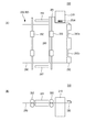
- 2A is a plan view of the post-processing apparatus
- FIG. 2B is a side view thereof.
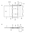
- 3A and 3B are diagrams for explaining an example of the operation of the post-processing apparatus when the binding process is performed.
- FIG. 3A is a plan view of the post-processing apparatus.
- B) is a side view thereof.
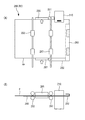
- FIGS. 4A and 4B are diagrams for explaining an example of the operation of the post-processing apparatus when the binding process is performed, and
- FIG. 4A is a plan view of the post-processing apparatus.
- B) is a side view thereof.
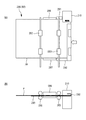
- FIGS. 5A and 5B are diagrams for explaining an operation example of the post-processing apparatus when the binding process is performed, and FIG. 5A is a plan view of the post-processing apparatus.
- B) is a side view thereof.
- FIGS. 6A and 6B are diagrams for explaining an example of the operation of the post-processing apparatus when performing the binding process, and FIG. 6A is a plan view of the post-processing apparatus.
- B) is a side view thereof.
- FIGS. 7A and 7B are diagrams for explaining an operation example of the post-processing apparatus when performing the binding process, and FIG. 7A is a plan view of the post-processing apparatus.
- B) is a side view thereof. It is a perspective view which shows the structural example of a binding apparatus.
- FIG. 12A is a cross-sectional view taken along the line AA in FIG. 11, and FIG. 12B is an enlarged view of a main part A in FIG. It is a figure which shows the structural example of a binding tooth.
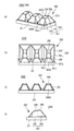
- FIGS. 14A to 14C are diagrams showing an example of the operation of the binding device when performing the crimping binding process.
- FIGS. 15A to 15D are diagrams showing an example of a process for binding and binding a sheet bundle with binding teeth.
- FIG. 16A is a perspective view of the lower teeth of the binding teeth, and FIG.
- FIG. 16B is the main part thereof.
- 17A is a plan view of the lower teeth of the binding teeth
- FIG. 17B is a front view thereof
- FIG. 17C is a side view thereof.
- FIG. 18A is a side view of the binding teeth when the lower teeth and the upper teeth are engaged with each other
- FIG. 18B is a cross-sectional plan view along the line BB.
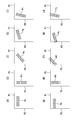
- FIGS. 19A to 19J are diagrams for explaining the binding positions of the binding portions Pa to Pj obtained by binding the sheet bundle with the binding teeth and performing the binding processing.
- 20A is a perspective view showing an example of the configuration of the lower teeth of the binding teeth
- FIG. 20B is a plan view thereof
- FIG. 20C is a front view thereof
- FIG. ) Is a side view thereof.
- 21A is a perspective view showing an example of the configuration of the lower teeth of the binding teeth
- FIG. 21B is a plan view thereof
- FIG. 21C is a front view thereof
- FIG. ) Is a side view thereof
- 22A is a perspective view showing an example of the configuration of the lower teeth of the binding teeth
- FIG. 22B is a plan view thereof
- FIG. 22C is a front view thereof
- FIG. ) Is a side view thereof
- 23A is a perspective view showing an example of the configuration of the lower teeth of the binding teeth
- FIG. 23B is a plan view thereof
- FIG. 23C is a front view thereof
- FIG. ) Is a side view thereof.
- FIG. 24A is a perspective view showing an example of the configuration of the lower teeth of the binding teeth
- FIG. 24B is a plan view thereof
- FIG. 24C is a front view thereof
- FIG. ) Is a side view thereof. It is a figure for demonstrating a side surface separation distance and a pressure contact distance.
- the distance between the lower teeth and the upper teeth of each binding teeth is changed, and the lateral separation distance is changed so that the pressure contact distance becomes 0 mm, the sheet bundle
- It is a figure which shows the verification result of the retention strength in a binding part. It is a figure for demonstrating elongation rate.
- FIG. 29 (A) to 29 (D) are diagrams showing the elongation rate in each cross section of the binding tooth shown in FIG. 28, and FIG. 29 (A) is a cross sectional view taken along the line ww. 29B is a cross-sectional view taken along line xx, FIG. 29C is a cross-sectional view taken along line yy, and FIG. 29D is a cross-sectional view taken along line zz.
- FIG. FIG. 30 (A) is a graph showing the rate of change in elongation when a plurality of types of binding teeth are used, and FIG. 30 (B) shows the shape of the binding teeth used in FIG.
- FIG. 30 (A) is a block diagram illustrating an example of a functional configuration of an image forming system.
- 6 is a flowchart illustrating an operation example of the post-processing apparatus when a print job including a binding instruction is executed.
- FIG. 1 shows an example of the configuration of the image forming system 300.
- the image forming system 300 includes an image forming apparatus 100 that forms an image on a sheet, and a post-processing apparatus 200 that performs crimping and the like on a plurality of sheet bundles on which images are formed. I have.
- the post-processing apparatus 200 constitutes an example of a sheet processing apparatus.
- the image forming apparatus 100 includes a document conveying unit 160, an image reading unit 170, a paper feeding unit 130, an image forming unit 110, a fixing unit 120, a display unit 140, and an input unit 150. .
- the document transport unit 160 feeds the document sheet set on the transport tray to the glass table.
- the image reading unit 170 generates image data by scanning a document set on a glass table or a document fed by the document transport unit 160 with a laser beam and reading it with a photoelectric exchange element.
- the paper feed unit 130 has a plurality of stages of paper feed trays that accommodate paper P of sizes A4, A3, etc., and takes out the paper P of the specified paper type at the start of the print job, and the image forming unit 110. Transport to.
- the image forming unit 110 forms a predetermined toner image by performing charging, exposure, and development processing on the surface of the photosensitive drum based on the input image data, and the surface of the paper P conveyed from the paper supply unit 130. Transfer the image to.
- the image forming unit 110 may employ a configuration capable of forming only a monochrome image, or may employ a configuration capable of forming a color image.
- the fixing unit 120 fixes the image on the paper P by performing pressure and heat treatment on the paper P on which the image has been transferred by the image forming unit 110.
- the sheets P fixed by the fixing unit 120 are sequentially carried out from the carry-out port to the post-processing device 200. Also, when performing duplex printing, the front and back of the paper P are reversed via a paper reversing path (not shown), and then the image is transferred to the back side of the paper P and carried out from the carry-out port to the post-processing device 200.
- the display unit 140 and the input unit 150 can be configured by a touch panel, operation buttons provided in the periphery thereof, and the like.
- the display unit 140 and the input unit 150 in addition to the image forming conditions such as the paper size and the number of printed sheets, the presence / absence of the crimp binding using the binding teeth and the staple binding using the staples, the number of bindings, the binding position, etc.
- the post-processing condition setting is configured to be input on the operation screen or operation buttons.
- FIG. 2 (A) is a plan view showing an example of the configuration of the post-processing apparatus 200
- FIG. 2 (B) is a side view thereof.
- the right side of the drawing corresponds to the lower side of the post-processing device 200
- the left side of the drawing corresponds to the upper side of the post-processing device 200.
- the post-processing device 200 is connected to the downstream side in the paper transport direction D of the image forming apparatus 100, and with respect to a paper bundle of paper P on which an image is formed by the image forming apparatus 100. Then, a booklet is created by performing crimp binding or staple binding.
- a known technique can be adopted for the staple binding, a detailed description thereof will be omitted.
- the post-processing apparatus 200 includes transport paths R1 and R2, a transport path switching unit 204, a binding device 210, and a paper stacking unit 280.
- the transport path R1 is a path through which the paper P is transported when binding processing such as crimp binding is not performed, and extends horizontally from the carry-in port toward the carry-out port.
- the transport path R2 is a path through which the paper P is transported when a binding process such as crimp binding is performed.
- the transport path R2 branches from the transport path R1 and extends in a substantially U shape, and is transported downstream from the branch portion. It joins the route R1.
- the transport route switching unit 204 is arranged at a branch portion of the transport routes R1 and R2, and switches the transport route based on the presence or absence of binding processing such as crimping.
- a solenoid can be used for the transport path switching unit 204.
- the paper stacking unit 280 includes transport rollers 282 and 283, side joggers 286 and 287, a paper stacking base 290, a guide member 291 and an end wall 292.
- the paper stacking unit 280 is provided in the transport path that extends from the bottom to the top of the transport path R2.
- the transport rollers 282 and 283 are provided so as to be able to rotate forward and backward, switch back transport the paper P carried into the transport path R2 and store it in the paper stacking unit 280, or stack the booklet for which the binding process has been completed.
- the sheet 280 is sent out to the paper discharge tray 206.
- the method for discharging the booklet to the paper discharge tray 206 is not limited to the method using the transport rollers 282 and 283, and the booklet is discharged by holding and transporting the booklet by a transport unit having a claw portion. You may make it discharge on the tray 206.
- the side joggers 286 and 287 are provided between the conveyance rollers 282 and 283 and at positions corresponding to the respective side portions of the paper P (on both sides of the conveyance path R2).
- the side joggers 286 and 287 are configured to be movable in the paper width direction, and align the side surfaces of the paper P stacked on the paper stacking unit 280.
- the paper P transported to the paper stacking unit 280 is sequentially stacked on the paper stacking base 290.
- the guide member 291 is formed in a substantially L shape so as to extend along the side surface from the front side of the binding position of the binding device 210, and guides the sheet bundle stacked on the paper stacking base 290 to the binding position of the binding device 210. Accordingly, the sheet bundle can be transported to the binding position so as not to be caught in the gap of the binding device 210 or the binding teeth 250A.
- the end wall 292 has a substantially U-shaped side surface, is disposed below the paper stacking base 290, and supports the front end portion (lower end) of the paper P conveyed to the paper stacking portion 280 in alignment.
- the end wall 292 is provided so as to be movable along the paper conveyance direction of the conveyance path R2, and can move between the home position (initial position) and the binding position.
- the end wall 292 and the guide member 291 are integrally formed, but may be formed separately.
- Two notches 292 a and 292 b are formed at the lower end of the end wall 292.
- An electric stapler (not shown) can be disposed in the notches 292a and 292b.
- the electric stapler may be configured to perform binding processing at one place or two places by moving between the notches 292a and 292b and changing the binding position with respect to the sheet bundle.
- the binding device 210 is provided in the paper stacking unit 280, and binds the paper bundle collected on the paper stacking base 290 by crimping with a pair of binding teeth 250A.
- the binding device 210 may be configured to be movable so that the binding position can be changed. At this time, you may enable it to move the binding apparatus 210 to the notch parts 292a and 292b mentioned above. The configuration and operation of the binding device 210 will be described later.
- FIGS. 5 to 7 are diagrams for explaining an example of the operation of the post-processing device 200 when the binding process is performed.
- 3 (A), FIG. 4 (A), FIG. 5 (A), FIG. 6 (A), and FIG. 7 (A) are plan views of the post-processing apparatus 200.
- FIG. 3 (B) and FIG. B), FIG. 5B, FIG. 6B, and FIG. 7B are side views thereof.
- the sheet bundle includes two or more sheets P stacked thereon.
- the right side of the drawing corresponds to the lower side of the post-processing apparatus 200
- the left side of the drawing corresponds to the upper side of the post-processing apparatus 200.
- the paper P on which the image is formed by the image forming apparatus 100 is transported to the transport path R2 of the post-processing apparatus 200. As shown in FIGS. 3A and 3B, the paper P transported to the transport path R ⁇ b> 2 is switchback transported by transport rollers 282 and 283, and is sequentially placed on the paper stacking table 290.
- each of the side joggers 286 and 287 moves inward to align the side surfaces of the paper P. Note that the operation of aligning the side surfaces of the paper P may be performed for each sheet or for a plurality of sheets.
- the side position is based on one end side of the paper P, only the side joggers 286 and 287 on one side may be moved.
- the side joggers 286 and 287 sandwich the side surface of the sheet bundle PP. Then, it moves to the binding device 210 side in the paper width direction. In other words, the sheet bundle is moved to the binding position by the side joggers 286 and 287, and the sheet width direction of the binding position is aligned.
- the end wall 292 moves upward. That is, the sheet bundle is moved to the binding position by the end wall 292, and the binding position in the sheet conveyance direction is aligned. As a result, the sheet bundle PP is set at the binding position designated by the user, and the binding process is performed on the sheet bundle by the binding device 210.
- the paper bundle PP is formed and then moved to the binding position. However, the paper P may be directly moved to the binding position one by one.
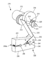
- FIG. 8 is a perspective view showing an example of the configuration of the binding device 210
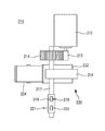
- FIG. 9 is a side view thereof
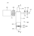
- FIG. 10 is a plan view thereof
- FIG. 11 is a front view thereof
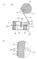
- 12A is a cross-sectional view taken along the line AA in FIG. 11, and
- FIG. 12B is an enlarged view of a main part A thereof. 8 to 12, the side on which the binding teeth 250A are provided is the front end side, and the opposite side is the rear end side.
- a binding device 210 equipped with an example of a drive unit includes a drive motor 212, an eccentric cam 216, a home position sensor (hereinafter referred to as HP sensor) 218, a timing sensor 220, , A binding tool 230.
- HP sensor home position sensor
- the drive unit is not limited to that described in this embodiment.
- the drive motor 212 is composed of, for example, a DC motor or a stepping motor, and is driven to rotate based on a binding command.
- the eccentric cam 216 is a disc cam and is connected to the motor gear 213 of the drive motor 212 via the gear 214 and rotates eccentrically as the drive motor 212 rotates.
- the eccentric cam 216 may be controlled to return to the home position by one rotation, or may be controlled to return to the home position by, for example, reverse rotation after rotating to the maximum load position.
- a drive shaft 217 protrudes from the surface of the eccentric cam 216 opposite to the drive motor 212.
- a detection piece 219 for HP sensor and a detection piece 221 for timing sensor each having a fan shape are attached to the drive shaft 217 from the eccentric cam 216 side.
- the detection piece 221 is formed with a central angle larger than that of the detection piece 219 and 180 ° or less in order to detect the rotational position of the eccentric cam 216 at intervals of 180 °.
- the HP sensor 218 is composed of, for example, a transmissive or reflective optical sensor, and is disposed in the vicinity of the detection piece 219. The HP sensor 218 detects whether the eccentric cam 216 is located at the home position based on the presence or absence of the detection piece 219.
- the timing sensor 220 is composed of, for example, a transmissive or reflective optical sensor, and is disposed in the vicinity of the detection piece 221. The timing sensor 220 detects the rotational position of the eccentric cam 216 based on the presence or absence of the detection piece 221.
- the binding tool 230 includes a pressing lever 232, an upper arm 234, a lower arm 236, a return spring 238, an elastic member 240, and a binding tooth 250A.
- the upper arm 234 and the lower arm 236 constitute an example of a drive unit.
- the pressing lever 232 is an elongated flat plate member, and the outer surface on one end side is in contact with the circumferential surface of the eccentric cam 216. At the other end of the pressing lever 232, protrusions 233 and 233 extending from the side surface in a direction orthogonal to the longitudinal direction of the pressing lever 232 are provided.
- the protrusions 233 and 233 are fitted into the rear end portion of the upper arm 234 from the outside, and are rotatably attached to the upper arm 234 via a lever fulcrum portion 246 made of a shaft member.
- the upper arm 234 has an elongated rectangular parallelepiped shape with an opening on the lower side.
- the lower arm 236 has an elongated rectangular parallelepiped shape whose upper side is opened, and is disposed to face the upper arm 234.
- the upper arm 234 and the lower arm 236 are configured to be rotatable with respect to each other via an arm fulcrum portion 242 made of a shaft member at a slightly distal end side from the center portion.
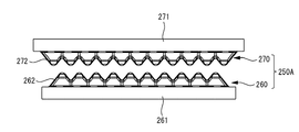
- FIG. 13 shows an example of the configuration of a binding tooth 250A as an example of a pair of tooth portions having a plurality of convex portions.
- the binding tooth 250 ⁇ / b> A includes a pair of lower teeth 260 and upper teeth 270.
- the lower teeth 260 are detachably attached to the distal end side of the lower arm 236, and the upper teeth 270 are detachably attached to the distal end side of the upper arm 234.
- the lower teeth 260 and the upper teeth 270 mesh with each other in a state where the sheet bundle is interposed, thereby crimping and binding the sheet bundle.
- the lower teeth 260 are an example in which a plurality of tooth portions 262 as an example of a plurality of convex portions are provided side by side.
- the upper tooth 270 is an example in which a plurality of tooth portions 262 as an example of a plurality of convex portions are arranged in parallel.
- a pair of tooth parts the example which provided the single tooth part 262 in the lower tooth and provided the single tooth part 262 in the upper tooth may be sufficient.
- a single tooth portion 262 may be provided on one of the lower teeth and the upper teeth, and a plurality of tooth portions 262 may be provided on the other.
- the binding teeth 250A will be described later.
- the return spring 238 is composed of, for example, a tension spring or the like, and has one end attached to the inside of the substantially central portion of the upper arm 234 and the other end to the inside of the substantially center of the lower arm 236 Is attached. In a state where no load is applied to the pressing lever 232, the distal end portion of the upper arm 234 and the distal end portion of the lower arm 236 are separated from each other by the urging of the return spring 238.
- the elastic member 240 is composed of, for example, a compression spring, and is attached to the inside of the rear end portion of the lower arm 236.
- the pressing member 244 is composed of a shaft member, is attached across the projecting portions 233 and 233, and the outer peripheral surface thereof is elastically supported by the upper end portion of the elastic member 240.
- the pressing member 244 moves to the rear side while pressing the elastic member 240 as the pressing lever 232 rotates, and moves the lever fulcrum 246 in a direction away from the upper arm 234.
- the elastic member 240 can also be configured from a leaf spring, rubber, resin material, or the like.
- FIGS. 14A to 14C are diagrams illustrating an example of the operation of the binding device 210 when performing the crimping binding process. As shown in FIG. 14A, until the binding command is received, the eccentric cam 216 is positioned at the home position, and the binding teeth 250A provided on the respective distal end portions of the upper arm 234 and the lower arm 236 are provided. Are in a separated state.
- the eccentric cam 216 is rotated by the rotational drive of the drive motor 212 to press one end of the pressing lever 232, and the pressing lever 232 is moved to the upper arm 234.
- the pressing member 244 moves to the rear side while pressing the elastic member 240 according to the applied load, and moves the lever fulcrum portion 246 of the pressing lever 232 in a direction away from the lower arm 236.
- the rear end side of the upper arm 234 is pushed upward, so that the tip end side of the upper arm 234 moves to the lower arm 236 side with the arm fulcrum 242 as a fulcrum, and the upper teeth 270 mesh with the lower teeth 260. It becomes a state.
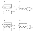
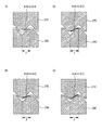
- 15 (A) to 15 (D) show an example of a process of crimping and binding the sheet bundle PP by meshing the binding teeth 250A.
- the sheet bundle PP with the front end and side surfaces aligned is conveyed to the binding position between the lower teeth 260 and the upper teeth 270.
- the upper teeth 270 move downward and the upper teeth 270 mesh with the lower teeth 260.
- FIG. 15D when the maximum load is applied to the upper teeth 270, the sheet bundle PP is deformed into a concavo-convex shape and pressed. Through such a process, a booklet that has been crimped and bound is created.
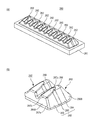
- FIG. 16A is a perspective view showing an example of the configuration of the lower teeth 260 constituting the binding teeth 250A according to the present invention, and FIG. 16B shows the main part thereof.
- 17A is a plan view of the lower teeth 260
- FIG. 17B is a front view thereof
- FIG. 17C is a side view thereof.
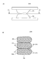
- 18A is a side view of the binding teeth 250A when the lower teeth 260 and the upper teeth 270 are engaged with each other
- FIG. 18B is a plan sectional view taken along the line BB. Since the lower teeth 260 and the upper teeth 270 have the same configuration, only the configuration of the lower teeth 260 will be described below as a representative.
- the lower teeth 260 include a base 261 having an elongated rectangular parallelepiped shape, and a plurality of tooth portions 262 as an example of a plurality of convex portions formed on the base 261.
- the tooth part 262 is an elongated ridge, and is made of a metal material such as SK material (carbon tool steel) or SUS material.
- the tooth portion 262 includes a side surface portion 263 as an example of an opposing surface facing the convex portion of the other tooth portion, a front surface portion 266A as an end surface portion as an example of an end surface configured as a surface along the convex direction, A surface portion 268 and an inclined surface portion 269 are provided.
- a first ridge line portion 267a is provided at a boundary portion between the front surface portion 266A and the side surface portion 263.
- a second ridge line portion 267b is provided at a boundary portion between the front surface portion 266A and the inclined surface portion 269.
- a third ridge line portion 267 c is provided at the boundary portion between the inclined surface portion 269 and the side surface portion 263.
- Each of the 1st ridgeline part 267a, the 2nd ridgeline part 267b, and the 3rd ridgeline part 267c is a curved surface which has roundness, for example.
- the side surface portion 263 is a surface that faces the side surface portion of the upper tooth 270 when the pair of upper teeth 270 are engaged with each other. Has the function of combining.
- the side surface portion 263 has a contact surface portion 264 and a non-contact surface portion 265.
- the contact surface portion 264 is a surface that is continuous with the top surface portion 268 and is a surface that contacts (contacts) the contact surface portion 274 facing the upper teeth 270 when the upper teeth 270 are engaged with each other without the paper P. It is.
- the non-contact surface portion 265 is a surface continuous with the contact surface portion 264, and is provided between the contact surface portion 264 and the first ridge line portion 267a.
- the non-contact surface portion 265 has a gap with the side surface portions of the upper teeth 270 that face each other when the upper teeth 270 are engaged with each other in the absence of the paper P (does not contact the side surfaces of the upper teeth 270). Surface.
- the non-contact surface portion 265 is weaker than the contact surface portion 264, but has a function of crimping the sheet bundle. Further, as shown in FIG.
- the non-contact surface portion 265 of the lower tooth 260 has a distance from the non-contact surface portion 275 (side surface portion 273) of the upper tooth 270 when the upper teeth 270 are engaged with each other. As an example, the distance increases toward the front surface 266A side (front).
- the non-contact surface portion 265 is composed of two surfaces having different angles, but may be composed of one surface or three or more surfaces.
- the top surface portion 268 is a surface provided on the top of the tooth portion 262, and is configured by a curved surface. Note that the top surface portion 268 can also be configured as a flat surface.
- the inclined surface portion 269 is a surface inclined from the top surface portion 268 toward the front surface portion 266A.
- the angle ⁇ formed by the top surface portion 268 and the inclined surface portion 269 is set in a range of 0 ° ⁇ ⁇ 20 °. By setting it within this range, as will be described later, it is possible to prevent local elongation of the paper when binding a bundle of paper, and to prevent the booklet from being torn.
- the front surface portion 266A is bent from one end side of the side surface portion 263, and is configured to be inclined with respect to the horizontal surface of the base 261 at, for example, more than 45 °. It faces the center (inner side) of the stack of paper.
- the rear surface portion 266B of the binding teeth 250 faces the outside of the sheet bundle, and is formed of, for example, a curved surface.
- the plurality of tooth portions 262 are arranged so as to be aligned in a direction perpendicular to the longitudinal direction of the tooth portions 262 so as to be arranged in a predetermined direction, and the longitudinal directions of the plurality of tooth portions 262 are parallel to each other. It is arranged to become.
- the length of the longitudinal direction of the some tooth part 262 is comprised by the same, it is not limited to this.
- the length in the longitudinal direction of the tooth portions 262 disposed at both ends of the plurality of tooth portions 262 may be configured to be longer than the length in the longitudinal direction of the tooth portions 262 disposed in the intermediate portion. it can.
- the lengths in the longitudinal direction of the side surfaces 263 and the like of the plurality of tooth portions 262 may be configured with different lengths, and the plurality of tooth portions 262 having different lengths in the longitudinal direction may be alternately arranged.
- the length of the tooth portion 262 in the longitudinal direction may be composed of a first length and two lengths that are longer than the first length, or may be composed of three or more different lengths. May be.
- the upper teeth 270 also have the same configuration as the lower teeth 260 shown in FIG. 16A and FIG.
- the upper teeth 270 include a side surface portion 273 including the contact surface portion 274 and the non-contact surface portion 275, a front surface portion 276A as an example of an end surface portion, a top surface portion 278, an inclined surface portion 279, A tooth portion 272 having one ridge line portion 277a, a second ridge line portion 277b, and a third ridge line portion 277c is provided (see FIGS. 16A and 16B).
- FIGS. 19A to 19J are diagrams for explaining binding positions of the binding portions Pa to Pj obtained by binding the sheet bundle with the binding teeth 250A and performing the binding processing.
- the binding portion Pa is in the vicinity of the corner portion of the sheet bundle, and the arrangement direction of the unevenness (hereinafter referred to as the unevenness of the binding portion) formed by the crimping of the binding process is the side P1. Formed along.
- the binding portion Pb is in the vicinity of the corner portion of the sheet bundle, and the arrangement direction of the unevenness of the binding portion Pb is formed along the side P1, and the entire binding portion Pb is the side. It is formed near the P2 side. Further, the binding portion Pb may be on the side P2.
- the binding portion Pc is in the vicinity of the corner portion of the sheet bundle, and the arrangement direction of the unevenness of the binding portion Pc is formed along the side P2.
- the binding portion Pd is in the vicinity of the corner portion of the sheet bundle, and the arrangement direction of the unevenness of the binding portion Pd is formed along the side P2, and the entire binding portion Pd is the side. Formed near the P1 side. Further, the binding portion Pd may cover the side P1.
- the binding portion Pe is in the vicinity of the corner portion of the sheet bundle, and the arrangement direction of the unevenness of the binding portion Pe is substantially 45 ° with respect to the sides P1 and P2. It is formed.
- the binding portion Pf is in the vicinity of the corner portion of the sheet bundle, and the arrangement direction of the unevenness of the binding portion Pf is substantially 45 ° with respect to the sides P1 and P2, and Both ends are formed at positions protruding from the sides P1 and P2 (positions straddling the corners).
- the binding portion Pg is in the vicinity of the corner of the sheet bundle, and the arrangement direction of the unevenness of the binding portion Pg is the arrangement direction of the unevenness of the binding portion Pe shown in FIG. It is formed so as to be slightly inclined with respect to the side P1.
- the binding portion Ph is formed in the vicinity of the corner portion of the sheet bundle and in the same direction as the arrangement direction of the unevenness of the binding portion Pg, and one end portion protrudes from the side P2. Formed at different positions.
- the binding portion Pi is in the vicinity of the corner portion of the sheet bundle, and the arrangement direction of the unevenness of the binding portion Pi is the arrangement direction of the unevenness of the binding portion Pe shown in FIG. It is formed so as to be slightly inclined with respect to the side P2.
- the binding portion Pj is formed in the vicinity of the corner portion of the sheet bundle and in the same direction as the arrangement direction of the unevenness of the binding portion Pi, and one end portion protrudes from the side P1. Formed at different positions.
- the front surface portion 266A as an example of the end surface portion of the binding teeth 250A is disposed so as to face the center side (inner side) of the sheet bundle. Yes. In this manner, by arranging the front surface portion 266A, it is possible to increase the peeling load when the paper is turned and peeled off from the bundle of paper that has been crimped and bound, thereby making it difficult to peel off the paper.
- the binding direction of the binding portions Pa to Pj is bound at a binding position in the range of 0 ° to 90 ° of the corner portion of the sheet bundle.
- the binding portion is preferably formed in a range of 0 ° to less than 30 °.
- [Modification of bound teeth] 20A is a perspective view showing an example of the configuration of the lower teeth 260 of the binding teeth 250B according to the present invention
- FIG. 20B is a plan view thereof
- FIG. 20C is a front view thereof
- FIG. 20D is a side view thereof. Note that elements having substantially the same functional configuration as the binding teeth 250 ⁇ / b> A are denoted by the same reference numerals and redundant description is omitted. Since the lower teeth 260 and the upper teeth 270 have the same configuration, only the configuration of the lower teeth 260 will be described below as a representative.
- the lower teeth 260 of the binding teeth 250B include a base 261 and a plurality of tooth portions 262 formed on the base 261.
- the tooth portion 262 includes a side surface portion 263 including a contact surface portion 264 and a non-contact surface portion 265, a front surface portion 266A as an example of an end surface portion, a first ridge line portion 267a, a top surface portion 268, and an inclined surface portion 269. ,have.
- the binding teeth 250B are configured such that the inclination angle of the inclined surface portion 269 is smaller than that of the binding teeth 250A and the surface thereof is formed with a curved surface.
- FIG. 21A is a perspective view showing an example of the configuration of the lower teeth 260 of the binding teeth 250C according to the present invention
- FIG. 21B is a plan view thereof
- FIG. 21C is a front view thereof
- FIG. 21D is a side view thereof. Note that elements having substantially the same functional configuration as the binding teeth 250 ⁇ / b> A are denoted by the same reference numerals and redundant description is omitted. Since the lower teeth 260 and the upper teeth 270 have the same configuration, only the configuration of the lower teeth 260 will be described below as a representative.
- the lower teeth 260 of the binding teeth 250C include a base 261 and a plurality of tooth portions 262 formed on the base 261.
- the tooth portion 262 includes a side surface portion 263 including a contact surface portion 264 and a non-contact surface portion 265, a front surface portion 266A as an example of an end surface portion, a first ridge line portion 267a, and a top surface portion 268.
- the binding tooth 250 ⁇ / b> C is different from the configuration of the binding tooth 250 ⁇ / b> A in that an inclined surface portion is not provided.
- FIG. 22A is a perspective view showing an example of the configuration of the lower teeth 260 of the binding teeth 250D according to the present invention
- FIG. 22B is a plan view thereof
- FIG. 22C is a front view thereof
- FIG. 22D is a side view thereof. Note that elements having substantially the same functional configuration as the binding teeth 250 ⁇ / b> A are denoted by the same reference numerals and redundant description is omitted. Since the lower teeth 260 and the upper teeth 270 have the same configuration, only the configuration of the lower teeth 260 will be described below as a representative.
- the lower teeth 260 of the binding teeth 250D include a base 261 and a plurality of tooth portions 262 formed on the base 261.
- the tooth portion 262 includes a side surface portion 263 including a contact surface portion 264 and a non-contact surface portion 265, a front surface portion 266A as an example of an end surface portion, a first ridge line portion 267a, a second ridge line portion 267b, and a top surface portion. 268 and an inclined surface portion 269.
- the binding teeth 250D are configured such that the area of the inclined surface portion 269 is smaller than that of the binding teeth 250A and the inclination angle of the front surface portion 266A is smaller.
- FIG. 23A is a perspective view showing an example of the configuration of the lower teeth 260 of the binding teeth 250E according to the present invention
- FIG. 23B is a plan view thereof
- FIG. 23C is a front view thereof
- FIG. 23D is a side view thereof. Note that elements having substantially the same functional configuration as the binding teeth 250 ⁇ / b> A are denoted by the same reference numerals and redundant description is omitted. Since the lower teeth 260 and the upper teeth 270 have the same configuration, only the configuration of the lower teeth 260 will be described below as a representative.
- the lower teeth 260 of the binding teeth 250E include a base 261 and a plurality of tooth portions 262 formed on the base 261.
- the tooth portion 262 includes a side surface portion 263 including a contact surface portion 264 and a non-contact surface portion 265, a front surface portion 266A as an example of an end surface portion, a first ridge line portion 267a, a second ridge line portion 267b, and a top surface portion. 268 and an inclined surface portion 269.
- the binding teeth 250E are configured such that the area of the inclined surface portion 269 is smaller than that of the binding teeth 250A and the inclination angle of the front surface portion 266A is smaller.
- FIG. 24A is a perspective view showing an example of the configuration of the lower teeth 260 of the binding teeth 250F according to the present invention
- FIG. 24B is a plan view thereof
- FIG. 24C is a front view thereof
- FIG. 24D is a side view thereof. Note that elements having substantially the same functional configuration as the binding teeth 250 ⁇ / b> A are denoted by the same reference numerals and redundant description is omitted. Since the lower teeth 260 and the upper teeth 270 have the same configuration, only the configuration of the lower teeth 260 will be described below as a representative.
- the lower teeth 260 of the binding teeth 250F include a plurality of tooth portions 262.
- the tooth portion 262 includes a side surface portion 263 including a contact surface portion 264 and a non-contact surface portion 265, a front surface portion 266A as an example of an end surface portion, a first ridge line portion 267a, a second ridge line portion 267b, and a top surface portion. 268 and an inclined surface portion 269.
- the binding teeth 250F differ from the configuration of the binding teeth 250A in that no base is provided.
- the press contact distance N is 0 mm or more when the side surface separation distance M is 0.23 mm or more and 0.35 mm or less when the sheet bundle is crimped.
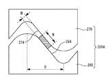
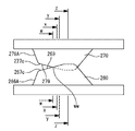
- FIG. 25 is a diagram for explaining the side surface separation distance M and the pressure contact distance N.
- the side surface separation distance M is the contact surface portion 264 of the lower tooth 260 and the contact surface portion 274 of the upper tooth 270 when the lower teeth 260 and the upper teeth 270 are engaged and the sheet bundle is crimped. Is the length of the normal between.
- the pressure contact distance N is a length in which the contact surface portion 264 of the lower tooth 260 and the contact surface portion 274 of the upper tooth 270 face each other in parallel when the lower teeth 260 and the upper teeth 270 are engaged and the sheet bundle is pressure-bonded. It is.
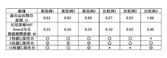
- FIG. 26 a plurality of types of binding teeth are used, the distance O between the lower teeth and the upper teeth of each binding teeth is changed, and the side surface separation distance M is changed so that the pressure contact distance N becomes 0 mm. In this case, the verification result of the holding force in the binding portion of the sheet bundle is shown.
- the distance O is a distance between the peak part and trough part of a lower tooth (upper tooth).
- the binding teeth 250A of the present invention having similar shapes with different sizes were used.
- the evaluation index of the holding force of the binding portion shown in FIG. 26 is as follows. (Double-circle): The binding part is sticking firmly and can fully be put into practical use as a binding booklet. ⁇ : When the paper is turned up, the binding portion is not easily peeled off. X: When the paper is turned up, the binding portion is easily peeled off.
- the distance O between the crests and troughs of the lower teeth is 0.63 mm to 0.96 mm
- the side surface separation distance M is 0.23 mm or more
- the binding holding force of 2, 5, or 10 sheets was “ ⁇ ” or “ ⁇ ”.
- Comparative Example 3 even when the distance O between the crests and troughs of the lower teeth is 1.09 mm and the pressure contact distance N is 0 mm when the side surface separation distance M is greater than 0.35 mm, 5 sheets The binding capacity of 10 sheets was “ ⁇ ” or “ ⁇ ”, but the binding capacity of 2 sheets was “ ⁇ ”. This is because when the number of sheet bundles is two and the side surface separation distance M exceeds 0.35 mm, the load due to the crimping is insufficient and binding cannot be performed sufficiently.
- the binding tooth 250A when the side surface separation distance M when the sheet bundle is pressed is 0.23 mm or more and 0.35 mm or less, the binding tooth 250A according to the present embodiment that can make the press contact distance N 0 mm. By using this, it is possible to suitably press and bind 2 to 10 sheet bundles that are generally used for pressure binding without tearing.
- the binding tooth 250A according to the present embodiment is used as the binding tooth.
- the present invention is not limited to this, and even when the above-described binding teeth 250B to 250F are used, the results shown in FIG. It was found that the same result was obtained.
- the pressure contact distance N is set to 0 mm or more when the side surface separation distance M is 0.23 mm or more and 0.35 mm or less.
- the side surface separation distance M is 0.23 mm or more and 0.35 mm or less, the same result as that shown in FIG.
- FIG. 27 is a diagram for explaining the elongation rate, and shows a part of a cross section in a direction orthogonal to the longitudinal direction of the tooth 250.
- the side surface separation distance M (see FIG. 25) between the lower teeth 260 and the upper teeth 270 is 0.09 mm.
- the side separation distance M 0.09 mm corresponds to the thickness of a sheet bundle after pressure bonding of two general copy sheets.
- the elongation rate is a virtual representation of the elongation with respect to the reference length when the sheet bundle is not crimped when the sheet bundle is engaged with the tooth 250 and is crimped.
- the elongation percentage is defined by the following formula (1) based on the lengths A to E of the respective portions of the binding teeth 250A shown in FIG.
- Elongation rate (A + B + C + D + E) / F (1)
- FIG. 28 shows a side view of the state where the lower teeth 260 and the upper teeth 270 are engaged with each other.
- 29 (A) to 29 (D) show the elongation percentage in each cross section of the binding tooth 250A shown in FIG.
- FIG. 29A is a cross-sectional view of the binding tooth 250A along the line ww
- FIG. 29B is a cross-sectional view of the binding tooth 250A along the line xx
- FIG. 29D is a cross-sectional view of the binding tooth 250A along the yy line
- FIG. 29D is a cross-sectional view of the binding tooth 250A along the zz line.
- the cross section along the line ww shown in FIG. 29A is a cross section at a position ww where the lower teeth 260 and the upper teeth 270 start to mesh.
- the non-contact surface portion 265 and the inclined surface portion 269 are provided on the binding teeth 250A, so that they extend toward the second ridge line portion 267b on the front surface portion 266A side.
- the rate can be gradually reduced. In this way, by gradually changing the elongation rate from the top surface portion 268 toward the front surface portion 266A, it is possible to prevent a rapid change in the elongation rate with reference to the start of meshing of the binding teeth 250A.
- the front portion 266A is shown as having a flat portion, but it is not always necessary to have a flat portion, and the front portion 266A is formed of a curved surface. Also good.
- the rate of change in elongation is the rate of change in elongation between two cross sections in the direction orthogonal to the longitudinal direction of the binding teeth 250A, and indicates how easily the sheet bundle is torn during crimping. It is an indicator.
- the change rate of the elongation rate is defined by the following formula (2).
- Elongation rate change ratio (Elongation rate Y ⁇ Elongation rate X) / Distance Z (2) Elongation rate X: Elongation rate at cross section X Elongation rate Y: Elongation rate at cross section Y Z: Distance between cross section X and cross section Y
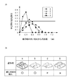
- FIG. 30 (A) is a graph showing the rate of change in elongation when multiple types of binding teeth are used.
- the vertical axis represents the rate of change of the elongation rate
- the horizontal axis represents the distance from the start of meshing of the teeth.
- FIG. 30B shows the shape of the binding teeth used in FIG. 30A, and the verification result of the binding booklet tearing when the binding processing of the sheet bundle is performed using these binding teeth. ing. Note that in FIG. 30B, ⁇ indicates that the binding booklet has not been torn, and x indicates that the binding booklet has torn.
- the binding tooth A is the binding tooth 250A described in the present embodiment, and has non-contact surface portions 265 and 275 and inclined surface portions 269 and 279.
- the binding tooth D is a conventional binding tooth and does not have a non-contact surface portion and an inclined surface portion.
- the binding teeth B and C have a non-contact surface, and the inclined surface portion has a curved shape.
- the binding tooth B is different from the binding tooth C in that it has a front surface portion.
- the sheet bundle used was composed of 10 sheets.
- the non-contact surface portions 265 and 275 and the inclined surface portions 269 and 279 are provided so that the rate of elongation change is meshed. It gradually increases from the beginning, and gradually decreases with a value less than 0.4 as a peak value. Accordingly, as shown in FIG. 30B, when the binding teeth A are used, the rate of change in the elongation rate does not exceed 0.4 as a peak value. Since the change can be prevented, no tearing occurred in the booklet after the binding process.
- the rate of change in the elongation rate increases rapidly from the beginning of the engagement of the binding tooth B, but the peak value of the rate of change in the elongation rate does not exceed 0.4, so the booklet after the binding process No tearing occurred.
- FIG. 31 is a block diagram illustrating an example of a functional configuration of the image forming system 300.
- the image forming system 300 includes an image forming apparatus 100 and a post-processing apparatus 200.
- the image forming apparatus 100 includes a control unit 102 for controlling the operation of each component.
- the control unit 102 includes a CPU (Central Processing Unit), a ROM (Read Only Memory), and the like.
- the CPU executes various functions related to image forming processing by reading and executing a program stored in the ROM.
- the display unit 140 and the input unit 150 are connected to the control unit 102, respectively.
- the display unit 140 and the input unit 150 supply information such as post-processing conditions input by the user to the control unit 202, or display a predetermined image on the screen based on control from the control unit 202.
- an external device 500 is connected to the control unit 102 via a network such as a LAN (Local Area Network) as an example.
- the external device 500 includes a personal computer, an information portable terminal, and the like, and communicates with the control unit 102 regarding image forming processing such as a print job.
- the post-processing device 200 includes a control unit 202 for controlling the operation of each component.
- the control unit 202 is connected to the control unit 102 of the image forming apparatus 100, and executes functions related to post-processing including pressure binding in conjunction with the control unit 102. Similar to the control unit 102, the control unit 202 includes a CPU, a ROM, and the like.
- the control unit 202 is connected to a binding device 210, a paper transport unit 284, a paper stacking unit 280, a door opening / closing detection unit 294, and a power supply unit 296.
- the binding device 210 includes a drive motor 212, an HP sensor 218, a timing sensor 220, and an encoder 224.
- the drive motor 212 is driven based on the drive signal supplied from the control unit 202 and rotates the eccentric cam 216. Note that an upper limit value may be set for the current value supplied to the drive motor 212 to prevent damage to the drive motor 212 due to overcurrent. Further, as a stop control of the drive motor 212, a short brake, a reverse brake, or a return at the time of overrun can be employed.
- the HP sensor 218 detects the presence or absence of the detection piece 219 indicating whether the eccentric cam 216 is at the home position, and supplies a detection signal to the control unit 202.
- the timing sensor 220 detects the presence or absence of the detection piece 221 indicating the rotational position of the eccentric cam 216 and supplies a detection signal to the control unit 202. For example, when an abnormality such as a failure of the binding device 210 occurs during the binding process and the timing sensor 220 is on, the control unit 202 has advanced the eccentric cam 216 from the half position, and the load Is after the peak, the drive motor 212 is controlled to return the eccentric cam 216 to the home position by forward rotation. On the other hand, when the abnormality occurs and the timing sensor 220 is off, the control unit 202 moves the eccentric cam 216 because the eccentric cam 216 has not advanced from the half position and the load is before the peak. The drive motor 212 is controlled to return to the home position by reverse rotation.
- Encoder 224 is attached to motor gear 213 (see FIG. 10) of drive motor 212, detects the rotational speed of drive motor 212, and supplies a detection signal to control unit 202.
- the control unit 202 controls, for example, the rotation speed of the drive motor 212 based on the rotation speed of the drive motor 212 detected by the encoder 224, thereby suppressing noise of the drive motor 212, for example.
- the paper transport unit 284 is composed of, for example, a DC motor, a stepping motor, or the like, and is driven based on a drive signal supplied from the control unit 202, whereby the transport rollers 282 and 283 of the transport path R1 and the transport rollers 282 and 283 of the transport path R2. Etc. are driven to rotate.
- the paper stacking unit 280 has a jogger driving unit 288 and an end wall driving unit 293.
- the jogger driving unit 288 is constituted by, for example, a DC motor or a stepping motor, and moves based on the driving signal supplied from the control unit 202 to move the side joggers 286 and 287 in the paper width direction.
- the end wall drive unit 293 is configured by, for example, a DC motor, a stepping motor, or the like, and is driven based on a drive signal supplied from the control unit 202 to move the end wall 292 to a binding position provided in the sheet conveyance direction. .
- the door opening / closing detection unit 294 detects the opening / closing operation of the opening / closing door provided on the near side of the post-processing device 200 and supplies a detection signal to the control unit 202.
- the power supply unit 296 is an AC power supply of 100 V, for example, and supplies power to the post-processing device 200.
- the control unit 202 controls the power supply unit 296 to stop the supply of power to the post-processing device 200. Thereby, when the post-processing apparatus 200 is abnormally stopped, the power can be turned off.
- FIG. 32 is a flowchart illustrating an example of a binding operation including a binding command.
- the CPU of the control unit 202 executes the processing shown in FIG. 32 by reading a program from a memory such as a ROM.
- step S100 the control unit 202 determines whether a print job including a binding command has been transmitted from the control unit 102, for example. When it is determined that the print job including the binding command has been transmitted, the control unit 202 proceeds to step S110, and when it is determined that the print job including the binding command has not been transmitted, the control unit 202 waits for the binding command.
- step S110 when the sheet bundle on which the image is formed is set at the binding position, the control unit 202 rotates the drive motor 212. Thereby, when the eccentric cam 216 makes one rotation, the teeth 250 change from the separated state to the meshed state, the sheet bundle is crimped and bound, and a booklet is created.
- step S120 the control unit 202 sets a timer for abnormality determination and starts counting as the drive motor 212 is driven to rotate.
- step S130 the control unit 202 determines whether the HP sensor 218 is turned on. That is, it is determined whether or not the eccentric cam 216 has returned to the home position after one rotation.
- the control unit 202 determines that the sheet bundle pressure-bonding process by the binding teeth 250A has been completed, proceeds to step S140, and stops the rotation of the drive motor 212.
- step S130 determines in step S130 that the HP sensor 218 is not turned on
- the process proceeds to step S150.
- step S150 the control unit 202 determines whether or not the set timer has timed out. If the timer has not timed out, the control unit 202 determines that the binding process by the teeth 250 has not been completed yet, returns to step S130, and continues to drive the drive motor 212.
- control unit 202 determines that an abnormality has occurred due to a failure of the drive motor 212 and the like, proceeds to step S160, and stops the rotational drive of the drive motor 212.
- step S160 the control unit 202 displays an error message on the screen of the display unit 140 or the screen of the external device 500 indicating that the binding process has not been completed normally. In the present embodiment, such processing is repeatedly executed.
- the non-contact surface portion 265 is provided between the contact surface portion 264 and the first ridge line portion 267a, or the top surface portion 268 and the second surface portion 268a. Since the inclined surface portion 269 is provided between the ridgeline portion 267b and the ridgeline portion 267b, local elongation of the paper P at the time of pressure bonding can be reduced. That is, the boundary portions between the side surface portion 263 and the inclined surface portion 269 and the first ridge line portion 267a and the second ridge line portion 267b can be gradually changed. Thereby, tearing of the paper P can be reliably prevented.
- the sheet P can be prevented from being torn, and therefore the number of sheets to be bound can be increased by increasing the pressing load. For example, it is possible to satisfactorily perform a binding process for a sheet bundle of about 5 to 10 sheets by pressure binding.
- the distance between the starting point of the booklet that has been crimped and bound and the starting point of the crimping part of the booklet is reduced, so that the holding force at the binding part of the booklet bundle can be improved.
- the non-contact surface portions 265 are provided on the side surface portions 263 of all the tooth portions 262 in the binding teeth 250A and the like, but the present invention is not limited to this.
- the non-contact surface portion 265 may be provided only on one side surface portion 263 of the tooth portion 262, or the non-contact surface portion 265 may be provided only on a specific tooth portion 262 among the plurality of tooth portions 262. May be.
- the non-contact surface portion 265 may be provided only on one of the lower teeth 260 and the upper teeth 270. The same applies to the inclined surface portion 269.
- the binding device 210 is mounted in the post-processing device 200 .
- the present invention is not limited to this, and the binding device 210 may be mounted in the image forming apparatus 100.
- the binding device 210 is installed downstream of the fixing unit 120 in the paper transport direction D.
- the binding edge of the sheet bundle is crimped by the binding device 210
- the present invention is not limited to this, and the vicinity of the folded portion of the half-folded booklet is crimped and bound. You may make it produce a booklet. In this case, it is preferable to arrange the arrangement direction of the unevenness of the crimping binding along the crease.
- the present invention is not limited to this.
- the lower teeth 260 and the upper teeth 270 may be arranged not in a straight line but in a curved shape or an annular shape, in a plurality of rows, or in a lattice shape.
- Image forming apparatus Post-processing apparatus (paper conveying apparatus) 212 Drive motor (drive unit) 230 Binding Tool 232 Pressing Lever 234 Upper Arm (Driver) 236 Lower arm (drive unit) 242 Arm fulcrum (shaft) 250A, 250B, 250C, 250D, 250E, 250F Binding teeth 260 Lower teeth (first teeth) 262 Tooth portion 263 Side surface portion 264 Contact surface portion 265 Non-contact surface portion 267a First ridge line portion 267b Second ridge line portion 267c Third ridge line portion 268 End surface portion (front surface portion) 269 Inclined surface portion 270 Upper teeth (second teeth) 280 Paper stacking unit (stacking unit) 284 Paper transport section (transport section) 300 Image forming system
Landscapes
- Engineering & Computer Science (AREA)
- Textile Engineering (AREA)
- Mechanical Engineering (AREA)
- Folding Of Thin Sheet-Like Materials, Special Discharging Devices, And Others (AREA)
- Paper Feeding For Electrophotography (AREA)
Abstract
一対の歯部は、互いに近接させたときに噛み合うように配置された複数の凸部を有する。一対の歯部のうちの少なくとも一方の歯部の凸部は、一対の歯部を噛み合わせたとき、他方の歯部の凸部と対向する対向面に、他方の歯部の凸部と当接する当接面と、前記他方の歯部の凸部と当接しない非当接面と、を有する。
Description
本発明は、歯部、綴じ具、用紙処理装置および画像形成システムに関する。
従来から、複数枚の用紙を積層した用紙束を綴じる綴じ具や、この綴じ具が搭載された用紙処理装置等が広く利用されている。綴じ具としては、ステープルを用いることが一般的であった。しかし、近年、省資源化や環境対策、リサイクル性の観点から、ステープル等の金属材料を用いない綴じ手段が注目されている。金属材料を用いない綴じ手段としては、例えば、上下一対の歯により用紙束を厚み方向に押圧して圧着することにより、用紙束を綴じるものが知られている。
例えば、特許文献1の綴じ具では、対をなす歯の傾斜面部の歯の接離方向に対する傾斜角度の絶対値が38°を下回るように構成される。そして、歯の傾斜面部で歯の間に積層させた用紙束を用紙素材の伸長を伴わせつつ圧接することにより、用紙が綴じられる。
また、特許文献2の用紙処理装置は、用紙束に凹凸状の加圧変形部を形成可能な固定歯型と、この固定歯型に対して接離可能な可動歯型と、を備える。そして、頂面の端部を丸み形状で構成した固定歯型および可動歯型により、用紙束が綴じ処理される。
また、特許文献2の用紙処理装置は、用紙束に凹凸状の加圧変形部を形成可能な固定歯型と、この固定歯型に対して接離可能な可動歯型と、を備える。そして、頂面の端部を丸み形状で構成した固定歯型および可動歯型により、用紙束が綴じ処理される。
しかしながら、上述した特許文献1に記載の綴じ具では、多くの枚数を綴じようとした場合、圧着するための領域(圧接面)を確保できず、綴じ枚数を増やすことができない。綴じ枚数を増やすためには、圧着後の綴じ厚さにおいて対をなす歯の側面部による圧接可能な距離を確保することが必要である。ところが、最小綴じ枚数の2枚綴じ時には、圧接距離が大きくなるため、従来と同様の圧力を得るためには、圧接距離に応じて綴じ荷重をアップさせる必要があり、荷重をアップさせることによって綴じ枚数が増加した時に用紙に破れが生じてしまうという問題があった。
また、上述した特許文献2に記載の用紙処理装置では、綴じ歯の端部や稜線を丸み形状にすることで、用紙の破れを防止することはできる。しかしながら、多くの枚数の用紙を綴じようとした場合、歯の角や稜線を丸み形状とするだけでは、用紙の破れ対策としては不十分であり、綴じの強度が低下してしまうという問題があった。
そこで、本発明は、上記課題に鑑みてなされたものであり、その目的は、多くの枚数を綴じるために綴じ荷重を増加させて用紙束を圧着綴じする場合において、用紙の破れを確実に防止することが可能な歯部、綴じ具、用紙処理装置および画像形成システムを提供することにある。
本発明は、例えば以下の形態を採用し得る。
(1) 互いに近接させたときに噛み合うように配置された複数の凸部を有する一対の歯部であって、
前記一対の歯部のうちの少なくとも一方の歯部の凸部は、前記一対の歯部を噛み合わせたとき、他方の歯部の凸部と対向する対向面に、前記他方の歯部の凸部と当接する当接面と、前記他方の歯部の凸部と当接しない非当接面と、を有する
ことを特徴とする歯部。
(2) 前記凸部は、前記対向面の一端側から屈曲し且つ凸方向に沿う面として構成される端面を有し、
前記非当接面は、前記当接面と前記端面との間に設けられる
ことを特徴とする(1)に記載の歯部。
(3) 前記凸部は、凸方向の一端側に形成される頂面を有し、
前記頂面は、頂部に向かって傾斜する傾斜面を有する
ことを特徴とする(1)に記載の歯部。
(4) 前記一対の歯部の複数の凸部は、それぞれ所定方向に列なるように配置される
ことを特徴とする(1)に記載の歯部。
(5) 前記一方の歯部の凸部の非当接面は、前記一対の歯部を噛み合わせたとき、前記他方の歯部の凸部の非当接面との距離が、前記端面側に向かうに従って大きくなるように構成される
ことを特徴とする(1)に記載の歯部。
(6) 前記所定方向に列なった複数の凸部のうち、両端部に配置された凸部の前記対向面の長手方向の長さは、前記複数の凸部のうち、中間部に配置された凸部の前記対向面の長手方向に長さよりも長く構成される
ことを特徴とする(4)に記載の歯部。
(7) 前記一対の歯部は、長手方向の長さが異なる前記対向面を有する複数の前記凸部を交互に配置してなる
ことを特徴とする(4)に記載の歯部。
(8) 互いに近接させたときに噛み合うように配置された複数の凸部を有する一対の歯部であって、
前記一対の歯部のうちの少なくとも一方の歯部の凸部は、前記一対の歯部を噛み合わせたとき、他方の歯部の凸部と対向する対向面に、前記他方の歯部の凸部と当接する当接面と、前記他方の歯部の凸部と当接しない非当接面とを有し、
前記一対の歯部を噛み合わせて、前記一方の歯部の凸部の対向面の当接面と、前記他方の歯部の凸部の対向面の当接面と、の間の法線の長さが0.23mm以上0.35mm以下のとき、前記一方の歯部の凸部の対向面の当接面と、前記他方の歯部の凸部の対向面の当接面と、が平行に対向する対向長さが0mm以上である
ことを特徴とする歯部。
(9) 対をなす第1の歯と第2の歯との噛み合わせにより用紙束を圧着して綴じる歯部であって、
前記第1の歯は、頂面部と、前面部と、側面部と、前記頂面部と前記前面部との間に設けられた傾斜面部と、前記傾斜面部と前記側面部との間に設けられた第3の稜線部と、を備え、
前記第2の歯は、頂面部と、前面部と、側面部と、前記頂面部と前記前面部との間に設けられた傾斜面部と、前記傾斜面部と前記側面部との間に設けられた第3の稜線部と、を備え、
前記第1の歯と前記第2の歯とを一定の間隔をあけて噛み合わせた際における、前記第1の歯の前記傾斜面部の直線部の半分の長さをAとし、前記第2の歯の前記傾斜面部の直線部の半分の長さをBとし、前記第1の歯の前記第3の稜線部と第2の歯の前記第3の稜線部との共通接線部の長さをCとし、前記第1の歯の前記第3の稜線部と前記傾斜面部の直線部との交点から共通接線部までの長さをDとし、前記第2の歯の前記第3の稜線部と前記傾斜面部の直線部との交点から共通接線部までの長さをEとし、前記第1の歯の前記傾斜面部の直線部の中心点と前記第2の歯の前記傾斜面部の直線部の中心点との間の長さをFとし、(A+B+C+D+E)/Fを伸び率とすると共に、
前記第1の歯と前記第2の歯とを一定の間隔をあけて噛み合わせた際における、前記第1の歯と前記第2の歯との長手方向で位置を異ならせた2箇所の前記伸び率をX,Yとし、前記伸び率Xの位置と伸び率Yの位置との間の距離をZとし、(Y-X)/Zを伸び率の変化割合としたとき、
前記伸び率の変化割合が0.4以下である
ことを特徴とする歯部。
(10) (1)~(9)のいずれか1つに記載の歯部と、
前記一対の歯部を互いに接離させる方向に駆動可能な駆動部と、
を備えた
ことを特徴とする綴じ具。
(11) 用紙を搬送する搬送部と、
前記搬送部により搬送された用紙を積載する積載部と、
前記積載部により積載された用紙束を綴じる(10)に記載の綴じ具と、
を備えた
ことを特徴とする用紙処理装置。
(12) 前記用紙束に対する前記綴じ具の位置を制御する位置制御部を備え、
前記位置制御部は、前記端面が前記用紙束の中央部側に向くように前記綴じ具の位置を制御する
ことを特徴とする(11)に記載の用紙処理装置。
(13) 用紙に画像を形成する画像形成装置と、
前記画像形成装置により画像が形成された用紙を搬送する搬送部と、
当該搬送部により搬送された用紙を積載する積載部と、
当該積載部に積載された用紙束を綴じる(10)に記載の綴じ具と、
を備えた
ことを特徴とする画像形成システム。
(1) 互いに近接させたときに噛み合うように配置された複数の凸部を有する一対の歯部であって、
前記一対の歯部のうちの少なくとも一方の歯部の凸部は、前記一対の歯部を噛み合わせたとき、他方の歯部の凸部と対向する対向面に、前記他方の歯部の凸部と当接する当接面と、前記他方の歯部の凸部と当接しない非当接面と、を有する
ことを特徴とする歯部。
(2) 前記凸部は、前記対向面の一端側から屈曲し且つ凸方向に沿う面として構成される端面を有し、
前記非当接面は、前記当接面と前記端面との間に設けられる
ことを特徴とする(1)に記載の歯部。
(3) 前記凸部は、凸方向の一端側に形成される頂面を有し、
前記頂面は、頂部に向かって傾斜する傾斜面を有する
ことを特徴とする(1)に記載の歯部。
(4) 前記一対の歯部の複数の凸部は、それぞれ所定方向に列なるように配置される
ことを特徴とする(1)に記載の歯部。
(5) 前記一方の歯部の凸部の非当接面は、前記一対の歯部を噛み合わせたとき、前記他方の歯部の凸部の非当接面との距離が、前記端面側に向かうに従って大きくなるように構成される
ことを特徴とする(1)に記載の歯部。
(6) 前記所定方向に列なった複数の凸部のうち、両端部に配置された凸部の前記対向面の長手方向の長さは、前記複数の凸部のうち、中間部に配置された凸部の前記対向面の長手方向に長さよりも長く構成される
ことを特徴とする(4)に記載の歯部。
(7) 前記一対の歯部は、長手方向の長さが異なる前記対向面を有する複数の前記凸部を交互に配置してなる
ことを特徴とする(4)に記載の歯部。
(8) 互いに近接させたときに噛み合うように配置された複数の凸部を有する一対の歯部であって、
前記一対の歯部のうちの少なくとも一方の歯部の凸部は、前記一対の歯部を噛み合わせたとき、他方の歯部の凸部と対向する対向面に、前記他方の歯部の凸部と当接する当接面と、前記他方の歯部の凸部と当接しない非当接面とを有し、
前記一対の歯部を噛み合わせて、前記一方の歯部の凸部の対向面の当接面と、前記他方の歯部の凸部の対向面の当接面と、の間の法線の長さが0.23mm以上0.35mm以下のとき、前記一方の歯部の凸部の対向面の当接面と、前記他方の歯部の凸部の対向面の当接面と、が平行に対向する対向長さが0mm以上である
ことを特徴とする歯部。
(9) 対をなす第1の歯と第2の歯との噛み合わせにより用紙束を圧着して綴じる歯部であって、
前記第1の歯は、頂面部と、前面部と、側面部と、前記頂面部と前記前面部との間に設けられた傾斜面部と、前記傾斜面部と前記側面部との間に設けられた第3の稜線部と、を備え、
前記第2の歯は、頂面部と、前面部と、側面部と、前記頂面部と前記前面部との間に設けられた傾斜面部と、前記傾斜面部と前記側面部との間に設けられた第3の稜線部と、を備え、
前記第1の歯と前記第2の歯とを一定の間隔をあけて噛み合わせた際における、前記第1の歯の前記傾斜面部の直線部の半分の長さをAとし、前記第2の歯の前記傾斜面部の直線部の半分の長さをBとし、前記第1の歯の前記第3の稜線部と第2の歯の前記第3の稜線部との共通接線部の長さをCとし、前記第1の歯の前記第3の稜線部と前記傾斜面部の直線部との交点から共通接線部までの長さをDとし、前記第2の歯の前記第3の稜線部と前記傾斜面部の直線部との交点から共通接線部までの長さをEとし、前記第1の歯の前記傾斜面部の直線部の中心点と前記第2の歯の前記傾斜面部の直線部の中心点との間の長さをFとし、(A+B+C+D+E)/Fを伸び率とすると共に、
前記第1の歯と前記第2の歯とを一定の間隔をあけて噛み合わせた際における、前記第1の歯と前記第2の歯との長手方向で位置を異ならせた2箇所の前記伸び率をX,Yとし、前記伸び率Xの位置と伸び率Yの位置との間の距離をZとし、(Y-X)/Zを伸び率の変化割合としたとき、
前記伸び率の変化割合が0.4以下である
ことを特徴とする歯部。
(10) (1)~(9)のいずれか1つに記載の歯部と、
前記一対の歯部を互いに接離させる方向に駆動可能な駆動部と、
を備えた
ことを特徴とする綴じ具。
(11) 用紙を搬送する搬送部と、
前記搬送部により搬送された用紙を積載する積載部と、
前記積載部により積載された用紙束を綴じる(10)に記載の綴じ具と、
を備えた
ことを特徴とする用紙処理装置。
(12) 前記用紙束に対する前記綴じ具の位置を制御する位置制御部を備え、
前記位置制御部は、前記端面が前記用紙束の中央部側に向くように前記綴じ具の位置を制御する
ことを特徴とする(11)に記載の用紙処理装置。
(13) 用紙に画像を形成する画像形成装置と、
前記画像形成装置により画像が形成された用紙を搬送する搬送部と、
当該搬送部により搬送された用紙を積載する積載部と、
当該積載部に積載された用紙束を綴じる(10)に記載の綴じ具と、
を備えた
ことを特徴とする画像形成システム。
(1)に係る発明によれば、対向面に非当接面部を設けることで、対をなす歯を噛み合わせて用紙束を綴じる圧着時における用紙の局所的な伸びを緩和することができ、これにより、用紙の破れを防止することができる。
(3)に係る発明によれば、さらに傾斜面を形成することで、用紙の局所的な伸びをよりいっそう緩和することができ、用紙の破れを防止できる。
(8)に係る発明によれば、側面離間距離が0.23mm以上0.35mm以下である場合に、圧接距離を0mm以上とすることで、綴じ枚数を多くした場合でも、対をなす第1の歯と第2の歯との噛み合わせによる用紙束の圧着時における用紙の破れを防止することができる。
(9)に係る発明によれば、伸び率の変化割合を0.4以下とすることで、対をなす第1の歯と第2の歯との噛み合わせによる用紙束の圧着時における用紙の局所的な伸びを緩和することができ、これにより、用紙の破れを防止することができる。
以下に添付図面を参照しながら、本発明の好適な実施の形態について詳細に説明する。なお、図面の寸法比率は、説明の都合上拡張されており、実際の比率と異なる場合がある。
[画像形成システム300の構成例]
図1は、画像形成システム300の構成の一例を示している。図1に示すように、画像形成システム300は、用紙に画像を形成する画像形成装置100と、画像が形成された複数枚の用紙束に対して圧着綴じ等を行う後処理装置200と、を備えている。なお、後処理装置200は、用紙処理装置の一例を構成している。
図1は、画像形成システム300の構成の一例を示している。図1に示すように、画像形成システム300は、用紙に画像を形成する画像形成装置100と、画像が形成された複数枚の用紙束に対して圧着綴じ等を行う後処理装置200と、を備えている。なお、後処理装置200は、用紙処理装置の一例を構成している。
画像形成装置100は、原稿搬送部160と、画像読取部170と、給紙部130と、画像形成部110と、定着部120と、表示部140と、入力部150と、を有している。
原稿搬送部160は、搬送トレイにセットされた原稿シートをガラス台に給送する。画像読取部170は、ガラス台上にセットされた原稿や原稿搬送部160により給送された原稿を、レーザー光により走査して光電交換素子で読みとることで画像データを生成する。給紙部130は、A4、A3等のサイズの用紙Pを収容する複数段の給紙トレイを有し、印刷ジョブの開始に伴って指定された紙種の用紙Pを取り出して画像形成部110に搬送する。
画像形成部110は、入力される画像データに基づいて感光体ドラムの表面に帯電、露光、現像処理を行うことにより所定のトナー像を形成し、給紙部130から搬送される用紙Pの表面に画像を転写する。なお、画像形成部110としては、モノクロ画像のみを形成可能な構成を採用しても良いし、カラー画像を形成可能な構成を採用しても良い。
定着部120は、画像形成部110により画像が転写された用紙Pに加圧、加熱処理を行うことにより画像を用紙Pに定着させる。定着部120により定着処理された用紙Pは、搬出口から後処理装置200に順次搬出される。また、両面印刷を行う場合には、図示しない用紙反転経路を経由して用紙Pの表裏が反転された後、用紙Pの裏面側に画像が転写され、搬出口から後処理装置200に搬出される。
表示部140および入力部150は、タッチパネルや、その周辺部に設けた操作ボタン等により構成することができる。表示部140および入力部150では、用紙サイズや印刷枚数等の画像形成条件の他に、綴じ歯を用いた圧着による圧着綴じやステープルを用いたステープル綴じ等の有無や綴じ枚数、綴じ位置等の後処理条件の設定を、操作画面や操作ボタンで入力できるように構成されている。
図2(A)は後処理装置200の構成の一例を示す平面図であり、図2(B)はその側面図である。なお、図2において、紙面右は後処理装置200の下側に対応し、紙面左は後処理装置200の上側に対応している。
図1および図2に示すように、後処理装置200は、画像形成装置100の用紙搬送方向Dの下流側に連結され、画像形成装置100で画像が形成された用紙Pの用紙束に対して、圧着綴じやステープル綴じを行って冊子を作成する。なお、以下において、ステープル綴じについては、公知の技術を採用することができるため、詳細な説明については省略する。
後処理装置200は、搬送経路R1,R2と、搬送経路切替部204と、綴じ装置210と、用紙積載部280と、を有している。
搬送経路R1は、圧着綴じ等の綴じ処理が行われない場合に用紙Pが搬送される経路であり、搬入口から搬出口に向かって水平に延在している。搬送経路R2は、圧着綴じ等の綴じ処理が行われる場合に用紙Pが搬送される経路であり、搬送経路R1から分岐して略U字形状に延在し、分岐部よりも下流側で搬送経路R1に合流している。
搬送経路切替部204は、搬送経路R1,R2の分岐部に配置され、圧着等の綴じ処理の有無に基づいて搬送経路の切り替えを行う。搬送経路切替部204には、例えばソレノイドを用いることができる。
用紙積載部280は、搬送ローラー282,283と、サイドジョガー286,287と、用紙積載台290と、ガイド部材291と、エンドウォール292と、を有している。用紙積載部280は、搬送経路R2の下方から上方に向かう搬送経路に設けられている。
搬送ローラー282,283は、正回転および逆回転可能に設けられ、搬送経路R2に搬入された用紙Pをスイッチバック搬送して用紙積載部280に収容したり、綴じ処理が完了した冊子を用紙積載部280から排紙トレイ206に送り出したりする。なお、冊子の排紙トレイ206への排出方法は、搬送ローラー282,283を用いた方法に限定されることはなく、爪部を有した搬送手段により冊子を保持して搬送することで排紙トレイ206上に排出するようにしても良い。
サイドジョガー286,287は、搬送ローラー282,283間であって、用紙Pの側面部のそれぞれに対応した位置(搬送経路R2の両側)に設けられている。サイドジョガー286,287は、用紙幅方向に移動可能に構成され、用紙積載部280に集積された用紙Pの側面位置を揃える。
用紙積載台290には、用紙積載部280に搬送される用紙Pが順次積載される。ガイド部材291は、綴じ装置210の綴じ位置の手前から側面に沿うように略L字状に形成され、用紙積載台290上に集積された用紙束を綴じ装置210の綴じ位置まで案内する。これにより、用紙束が綴じ装置210の隙間や綴じ歯250Aに引っ掛からないように綴じ位置まで搬送することができる。
エンドウォール292は、側面形状が略コの字形状からなり、用紙積載台290の下方に配置され、用紙積載部280に搬送される用紙Pの先端部(下端部)を揃えて支持する。エンドウォール292は、搬送経路R2の用紙搬送方向に沿って移動可能に設けられ、ホームポジション(初期位置)と綴じ位置との間を移動できるようになっている。なお、本実施の形態では、エンドウォール292とガイド部材291とを一体に形成しているが、別体で形成することもできる。エンドウォール292の下端部には、二つの切欠き部292a,292bが形成されている。切欠き部292a,292bには、図示しない電動ステープラを配置することができる。電動ステープラは、切欠き部292a,292b間を移動し、用紙束に対する綴じ位置を変更することにより一箇所または二箇所を綴じ処理するように構成されても良い。
綴じ装置210は、用紙積載部280に設けられ、用紙積載台290に集積された用紙束を一対の綴じ歯250Aにより圧着することで綴じる。本実施の形態では、綴じ装置210を固定して設置した例について説明しているが、綴じ装置210を移動可能な構成とし、綴じ位置を変更できるようにしても良い。このとき、上述した切欠き部292a,292bに綴じ装置210を移動できるようにしても良い。なお、綴じ装置210の構成や動作については、後述する。
[後処理装置200の動作例]
図3~図7は、綴じ処理を行う場合における後処理装置200の動作の一例を説明するための図である。図3(A),図4(A),図5(A),図6(A),図7(A)は、後処理装置200の平面図であり、図3(B),図4(B),図5(B),図6(B),図7(B)は、その側面図である。なお、図5~図7では、2枚以上の用紙Pが積載された用紙束であるものとする。また、図3~図7において、紙面右は後処理装置200の下側に対応し、紙面左は後処理装置200の上側に対応している。
図3~図7は、綴じ処理を行う場合における後処理装置200の動作の一例を説明するための図である。図3(A),図4(A),図5(A),図6(A),図7(A)は、後処理装置200の平面図であり、図3(B),図4(B),図5(B),図6(B),図7(B)は、その側面図である。なお、図5~図7では、2枚以上の用紙Pが積載された用紙束であるものとする。また、図3~図7において、紙面右は後処理装置200の下側に対応し、紙面左は後処理装置200の上側に対応している。
画像形成装置100で画像が形成された用紙Pは、後処理装置200の搬送経路R2に搬送される。図3(A)および図3(B)に示すように、搬送経路R2に搬送された用紙Pは、搬送ローラー282,283によりスイッチバック搬送され、用紙積載台290上に順次載置される。
次に、図4(A)および図4(B)に示すように、用紙Pが用紙積載台290上に載置されると、搬送ローラー282,283の用紙Pとの当接状態が解除されると共に回転が停止される。続けて、サイドジョガー286,287のそれぞれが内側方向に移動し、用紙Pの側面位置を揃える。なお、用紙Pの側面位置の揃え動作は、用紙一枚毎に行っても良いし、複数枚毎に行っても良い。また、側面位置として用紙Pの一方の端部側を基準とする場合には、一方側のサイドジョガー286,287のみを移動するようにしても良い。
次に、図5(A)および図5(B)に示すように、指定された枚数の用紙Pの側面揃えが完了したら、サイドジョガー286,287が用紙束PPの側面部を挟んだ状態で、用紙幅方向における綴じ装置210側に移動する。つまり、サイドジョガー286,287により用紙束が綴じ位置に移動され、綴じ位置の用紙幅方向が位置合わせされる。
次に、図6(A)および図6(B)に示すように、サイドジョガー286,287による移動が終了すると、エンドウォール292が上方側に移動する。つまり、エンドウォール292により用紙束が綴じ位置まで移動され、用紙搬送方向の綴じ位置が位置合わせされる。これにより、用紙束PPがユーザーにより指定された綴じ位置にセットされ、綴じ装置210により用紙束に綴じ処理が行われる。なお、上述した実施の形態では、用紙束PPを形成した後に綴じ位置に移動させるようにしたが、用紙Pを一枚単位で直接綴じ位置に移動させるようにしても良い。
次に、図7(A)および図7(B)に示すように、綴じ処理が終了すると、搬送ローラー282,283が再度用紙Pと当接されると共に回転駆動される。これにより、綴じ処理が行われた用紙束PPが用紙積載台290から搬送され、排紙ローラーを介して排紙トレイ206上に排出される。
[綴じ装置210の構成例]
図8は綴じ装置210の構成の一例を示す斜視図であり、図9はその側面図であり、図10はその平面図であり、図11はその正面図である。図12(A)は図11のA-A線に沿った断面図であり、図12(B)はその要部Aの拡大図である。なお、図8~図12において、綴じ歯250Aが設けられる側を先端側とし、その反対側を後端側とする。
図8は綴じ装置210の構成の一例を示す斜視図であり、図9はその側面図であり、図10はその平面図であり、図11はその正面図である。図12(A)は図11のA-A線に沿った断面図であり、図12(B)はその要部Aの拡大図である。なお、図8~図12において、綴じ歯250Aが設けられる側を先端側とし、その反対側を後端側とする。
図8~図12に示すように、駆動部の一例を搭載した綴じ装置210は、駆動モータ212と、偏芯カム216と、ホームポジションセンサ(以下、HPセンサという)218と、タイミングセンサ220と、綴じ具230と、を備えている。なお、駆動部は、本実施の形態に記載したものに限定されるものではない。
駆動モータ212は、例えばDCモータやステッピングモータ等から構成され、綴じ指令に基づいて回転駆動する。
偏芯カム216は、円板カムであって、ギア214を介して駆動モータ212のモータギア213に接続され、駆動モータ212の回転に伴って偏芯回転する。なお、偏芯カム216は、一回転でホームポジションに戻るように制御しても良いし、例えば最大荷重位置まで回転させた後に逆回転させることでホームポジションに戻すように制御しても良い。
偏芯カム216の駆動モータ212とは反対側の面には、駆動軸217が突設されている。駆動軸217には、偏芯カム216側から扇形状をなすHPセンサ用の検出片219およびタイミングセンサ用の検出片221がそれぞれ取り付けられている。一例として検出片221は、偏芯カム216の回転位置を180°間隔で検出するため、検出片219よりも中心角が大きくかつ180°以下で形成される。
HPセンサ218は、例えば透過型または反射型の光センサから構成され、検出片219の近傍に配置されている。HPセンサ218は、検出片219の有無に基づいて偏芯カム216がホームポジションに位置しているかを検出する。タイミングセンサ220は、例えば透過型または反射型の光センサから構成され、検出片221の近傍に配置されている。タイミングセンサ220は、検出片221の有無に基づいて偏芯カム216の回転位置を検出する。
綴じ具230は、押圧レバー232と、上アーム234と、下アーム236と、リターンばね238と、弾性部材240と、綴じ歯250Aと、を有している。なお、上アーム234および下アーム236は、駆動部の一例を構成している。
押圧レバー232は、細長の平板部材であって、一端側の外面が偏芯カム216の周面に当接している。押圧レバー232の他端部には、その側面から押圧レバー232の長手方向に対して直交する方向に延びる突出部233,233が設けられている。突出部233,233は、上アーム234の後端部に外側から嵌め込まれ、軸部材からなるレバー支点部246を介して上アーム234に回動可能に取り付けられている。
上アーム234は、下方側が開口された細長の直方体形状からなる。下アーム236は、上方側が開口された細長の直方体形状からなり、上アーム234に対向して配置されている。上アーム234と下アーム236は、中央部より若干先端側において軸部材からかなるアーム支点部242を介して互いに回動可能に構成されている。
図13は、複数の凸部を有する一対の歯部の一例としての綴じ歯250Aの構成の一例を示している。図12(B)および図13に示すように、綴じ歯250Aは、一対の下歯260および上歯270から構成されている。下歯260は下アーム236の先端部側に着脱可能に取り付けられ、上歯270は上アーム234の先端部側に着脱可能に取り付けられている。下歯260および上歯270は、用紙束が介在している状態で互いに噛み合うことで用紙束を圧着して綴じる。下歯260は、複数の凸部の一例としての複数の歯部262を並設した一例である。上歯270は、複数の凸部の一例としての複数の歯部262を並設した一例である。一対の歯部の一例としては、下歯に単数の歯部262を設け、上歯に単数の歯部262を設けた例であってもよい。また、一対の歯部の一例としては、下歯と上歯のうち、一方に単数の歯部262を設け、他方に複数の歯部262を設けた例であってもよい。なお、綴じ歯250Aについては後述する。
図8~図12に戻り、リターンばね238は、例えば引っ張りばね等から構成され、一端部が上アーム234の略中央部の内側に取り付けられ、他端部が下アーム236の略中央部の内側に取り付けられている。押圧レバー232に荷重がかかっていない状態では、リターンばね238の付勢により、上アーム234の先端部と下アーム236の先端部とが離間した状態とされる。
弾性部材240は、例えば圧縮ばねから構成され、下アーム236の後端部の内側に取り付けられている。押圧部材244は、軸部材から構成され、突出部233,233間に跨って取り付けられると共に、その外周面が弾性部材240の上端部によって弾性的に支持されている。押圧部材244は、押圧レバー232の回動に伴って弾性部材240を押圧しながら後部側に移動すると共に、レバー支点部246を上アーム234から離れる方向に移動させる。なお、弾性部材240は、板バネやゴム、樹脂材料等から構成することもできる。
[綴じ装置210の動作例]
図14(A)~図14(C)は、圧着綴じ処理を行う場合における綴じ装置210の動作の一例を示す図である。図14(A)に示すように、綴じ指令を受けるまでは、偏芯カム216がホームポジションに位置しており、上アーム234および下アーム236のそれぞれの先端部側に設けられた綴じ歯250Aは離間した状態とされる。
図14(A)~図14(C)は、圧着綴じ処理を行う場合における綴じ装置210の動作の一例を示す図である。図14(A)に示すように、綴じ指令を受けるまでは、偏芯カム216がホームポジションに位置しており、上アーム234および下アーム236のそれぞれの先端部側に設けられた綴じ歯250Aは離間した状態とされる。
図14(B)に示すように、綴じ指令を受けると、駆動モータ212の回転駆動により偏芯カム216が回転して押圧レバー232の一端部側を押圧し、押圧レバー232が上アーム234に接近する方向に移動する。押圧部材244は、付与される荷重に応じて弾性部材240を押圧しながら後部側に移動すると共に、押圧レバー232のレバー支点部246を下アーム236から離れる方向に移動させる。これに伴い、上アーム234の後端部側が上方に押し上げられることで、上アーム234の先端部側がアーム支点部242を支点として下アーム236側に移動し、上歯270が下歯260に噛み合った状態となる。
図14(C)に示すように、上歯270と下歯260の噛み合いを最大荷重の状態とする場合、駆動モータ212の回転駆動により偏芯カム216が回転し、押圧レバー232が上アーム234にさらに接近する方向に移動する。これに伴い、押圧部材244は、付与される最大荷重に応じて弾性部材240を押圧しながら後部側に移動する。これにより、上アーム234の後端部が若干上方に押し上げられることで、下歯260と上歯270との噛み合いが最大荷重となる。また、弾性部材240は、押圧部材244からの最大荷重により収縮することで、荷重を逃がすと共に、押圧レバー232の移動が停止してロック状態となることを防止する。
図15(A)~図15(D)は、綴じ歯250Aの噛み合わせにより用紙束PPを圧着して綴じる工程の一例を示している。図15(A)に示すように、先端や側面が揃えられた用紙束PPが下歯260と上歯270との間の綴じ位置まで搬送される。続けて、図15(B)および図15(C)に示すように、上歯270が下方に移動していき、上歯270が下歯260に噛み合う。続けて、図15(D)に示すように、上歯270に最大荷重が付与されると、用紙束PPが凹凸状に変形して圧着される。このような工程により、圧着綴じされた冊子が作成される。
[綴じ歯250Aの構成例]
図16(A)は本発明に係る綴じ歯250Aを構成する下歯260の構成の一例を示す斜視図であり、図16(B)はその要部を示している。図17(A)は下歯260の平面図であり、図17(B)はその正面図であり、図17(C)はその側面図である。図18(A)は下歯260と上歯270とを噛み合わせた際の綴じ歯250Aの側面図であり、図18(B)はそのB-B線に沿った平断面図である。なお、下歯260と上歯270とは構成が同一であるため、以下では下歯260の構成のみを代表して説明する。
図16(A)は本発明に係る綴じ歯250Aを構成する下歯260の構成の一例を示す斜視図であり、図16(B)はその要部を示している。図17(A)は下歯260の平面図であり、図17(B)はその正面図であり、図17(C)はその側面図である。図18(A)は下歯260と上歯270とを噛み合わせた際の綴じ歯250Aの側面図であり、図18(B)はそのB-B線に沿った平断面図である。なお、下歯260と上歯270とは構成が同一であるため、以下では下歯260の構成のみを代表して説明する。
図16~図18に示すように、下歯260は、細長の直方体形状からなる基台261と、基台261上に形成された複数の凸部の一例としての複数の歯部262と、を備えている。歯部262は、細長の凸条体であって、例えばSK材(炭素工具鋼)やSUS材等の金属材料からなる。歯部262は、他方の歯部の凸部と対向する対向面の一例としての側面部263と、凸方向に沿う面として構成される端面の一例としての端面部である前面部266Aと、頂面部268と、傾斜面部269と、を有している。前面部266Aと側面部263との境界部には、第1の稜線部267aが設けられている。前面部266Aと傾斜面部269との境界部には、第2の稜線部267bが設けられている。傾斜面部269と側面部263との境界部には、第3の稜線部267cが設けられている。第1の稜線部267a、第2の稜線部267bおよび第3の稜線部267cのそれぞれは、例えば丸みを有する曲面である。
側面部263は、対をなす上歯270が噛み合わされた際に上歯270の側面部に対向する面であって、上歯270との間に用紙Pを挟んで圧着することにより用紙同士を結合させる機能を有している。側面部263は、当接面部264と、非当接面部265と、を有している。
当接面部264は、頂面部268に連続する面であると共に、用紙Pがない状態で上歯270が噛み合わされた際に上歯270の対向する当接面部274と当接(接触)する面である。
非当接面部265は、当接面部264に連続する面であって、当接面部264と第1の稜線部267aとの間に設けられている。非当接面部265は、用紙Pが無い状態で上歯270が噛み合わされた際に、上歯270の対向する側面部との間に隙間を有する(上歯270の側面部に当接しない)面である。なお、非当接面部265は、当接面部264よりも弱いが用紙束を圧着する機能を有している。また、下歯260の非当接面部265は、図18に示すように、上歯270が噛み合わされた際における上歯270の非当接面部275(側面部273)との距離が、端面部の一例としての前面部266A側(前方)に向かうに従って大きくなっている。この非当接面部265を設けることで、第1の稜線部267a、第2の稜線部267bおよび第3の稜線部267cでの用紙の局所的な伸びを緩和することができる。なお、本実施の形態では、非当接面部265を角度の異なる2面で構成しているが、1面で構成しても良いし、3面以上で構成しても良い。
頂面部268は、歯部262の頂上に設けられる面であり、湾曲面で構成されている。なお、頂面部268は、平面で構成することもできる。
傾斜面部269は、頂面部268から前面部266Aに向かって傾斜する面である。本実施の形態では、図17(C)に示すように、頂面部268と傾斜面部269とのなす角度αが、0°<α≦20°の範囲に設定される。この範囲とすることで、後述するように、用紙束を綴じ処理する際における用紙の局所的な伸びを防止することができ、冊子の破れを防止できる。
前面部266Aは、側面部263の一端側から屈曲し、基台261の水平面に対して角度が例えば45°超で傾斜するように構成されており、用紙Pを挟んで綴じる位置において圧着綴じする用紙束の中央側(内側)を向いている。なお、綴じ歯250の後面部266Bは、用紙束の外側を向いており、例えば湾曲面で構成される。
複数の歯部262は、それぞれ所定方向に列なるように歯部262の長手方向とは直交する方向に沿って並ぶように配置されると共に、複数の歯部262の長手方向のそれぞれが互いに平行となるように配置されている。
なお、図17(A)等では、複数の歯部262の長手方向の長さを同一で構成しているが、これに限定されることはない。例えば、複数の歯部262のうち両端側に配置される歯部262の長手方向の長さが、中間部に配置される歯部262の長手方向の長さよりも長くなるように構成することもできる。また、複数の歯部262の側面部263等の長手方向の長さをそれぞれ異なる長さで構成し、長手方向の長さが異なる複数の歯部262を交互に配置することもできる。歯部262の長手方向の長さは、第1の長さと、これよりも長い第2の長さの2つの長さと、で構成しても良いし、3つ以上の異なる長さで構成しても良い。
また、上歯270についても、図16(A)および図16(B)等で示した下歯260とは符号が異なるのみで、それ以外の構成は共通している。図示は省略するが、上歯270は、当接面部274および非当接面部275を含む側面部273と、端面部の一例としての前面部276Aと、頂面部278と、傾斜面部279と、第1の稜線部277aと、第2の稜線部277bと、第3の稜線部277cと、を有する歯部272を備えている(図16(A)および図16(B)参照)。
[綴じ部の綴じ位置について]
図19(A)~図19(J)は、綴じ歯250Aにより用紙束を圧着して綴じ処理した綴じ部Pa~Pjの綴じ位置を説明するための図である。
図19(A)~図19(J)は、綴じ歯250Aにより用紙束を圧着して綴じ処理した綴じ部Pa~Pjの綴じ位置を説明するための図である。
図19(A)に示すように、綴じ部Paは、用紙束の角部の近傍であって、綴じ処理の圧着により形成される凹凸(以下、綴じ部の凹凸という)の配列方向が辺P1に沿って形成される。図19(B)に示すように、綴じ部Pbは、用紙束の角部の近傍であって、綴じ部Pbの凹凸の配列方向が辺P1に沿って形成されると共に綴じ部Pb全体が辺P2側に寄って形成される。また、綴じ部Pbは、辺P2にかかっても良い。
図19(C)に示すように、綴じ部Pcは、用紙束の角部の近傍であって、綴じ部Pcの凹凸の配列方向が辺P2に沿って形成される。図19(D)に示すように、綴じ部Pdは、用紙束の角部の近傍であって、綴じ部Pdの凹凸の配列方向が辺P2に沿って形成されると共に綴じ部Pd全体が辺P1側に寄って形成される。また、綴じ部Pdは、辺P1にかかっても良い。
図19(E)に示すように、綴じ部Peは、用紙束の角部の近傍であって、綴じ部Peの凹凸の配列方向が辺P1,P2に対して互いに略45°となるように形成される。図19(F)に示すように、綴じ部Pfは、用紙束の角部の近傍であって、綴じ部Pfの凹凸の配列方向が辺P1,P2に対して互いに略45°となると共にその両端部が各辺P1,P2からはみ出した位置(角部を跨いだ位置)に形成される。
図19(G)に示すように、綴じ部Pgは、用紙束の角部の近傍であって、綴じ部Pgの凹凸の配列方向が図19(E)に示す綴じ部Peの凹凸の配列方向よりも辺P1に対して若干緩やかに傾斜するように形成される。図19(H)に示すように、綴じ部Phは、用紙束の角部の近傍であって、綴じ部Pgの凹凸の配列方向と同一方向に形成されると共に、一端部が辺P2からはみ出した位置に形成される。
図19(I)に示すように、綴じ部Piは、用紙束の角部の近傍であって、綴じ部Piの凹凸の配列方向が図19(E)に示す綴じ部Peの凹凸の配列方向よりも辺P2に対して若干緩やかに傾斜するように形成される。図19(J)に示すように、綴じ部Pjは、用紙束の角部の近傍であって、綴じ部Piの凹凸の配列方向と同一方向に形成されると共に、一端部が辺P1からはみ出した位置に形成される。
図19(A)~図19(J)に示した何れの場合でも、綴じ歯250Aの端面部の一例としての前面部266Aは、用紙束の中央側(内側)を向くように配設されている。このように、前面部266Aを配置することで、圧着綴じされた用紙束から用紙をめくり剥がす際の剥がし荷重を大きくして、用紙を剥がれ難くすることができる。
なお、本実施の形態では、綴じ部Pa~Pjの配列方向を用紙束の角部の0°~90°の範囲の綴じ位置で綴じる場合について説明したが、より好ましくは用紙Pの紙目方向に対して0°~30°未満の範囲で綴じ部を形成することが好ましい。
[綴じ歯の変形例]
図20(A)は本発明に係る綴じ歯250Bの下歯260の構成の一例を示す斜視図であり、図20(B)はその平面図であり、図20(C)はその正面図であり、図20(D)はその側面図である。なお、綴じ歯250Aと、実質的に同一の機能構成を有する要素については、同一の符号を付すと共に重複する説明を省略する。また、下歯260と上歯270とは構成が同一であるため、以下では下歯260の構成のみを代表して説明する。
図20(A)は本発明に係る綴じ歯250Bの下歯260の構成の一例を示す斜視図であり、図20(B)はその平面図であり、図20(C)はその正面図であり、図20(D)はその側面図である。なお、綴じ歯250Aと、実質的に同一の機能構成を有する要素については、同一の符号を付すと共に重複する説明を省略する。また、下歯260と上歯270とは構成が同一であるため、以下では下歯260の構成のみを代表して説明する。
綴じ歯250Bの下歯260は、基台261と、基台261上に形成された複数の歯部262と、を備えている。歯部262は、当接面部264および非当接面部265を含む側面部263と、端面部の一例としての前面部266Aと、第1の稜線部267aと、頂面部268と、傾斜面部269と、を有している。綴じ歯250Bは、綴じ歯250Aよりも、傾斜面部269の傾斜角度が小さくなると共にその面が曲面で形成されて構成されている。
図21(A)は本発明に係る綴じ歯250Cの下歯260の構成の一例を示す斜視図であり、図21(B)はその平面図であり、図21(C)はその正面図であり、図21(D)はその側面図である。なお、綴じ歯250Aと、実質的に同一の機能構成を有する要素については、同一の符号を付すと共に重複する説明を省略する。また、下歯260と上歯270とは構成が同一であるため、以下では下歯260の構成のみを代表して説明する。
綴じ歯250Cの下歯260は、基台261と、基台261上に形成された複数の歯部262と、を備えている。歯部262は、当接面部264および非当接面部265を含む側面部263と、端面部の一例としての前面部266Aと、第1の稜線部267aと、頂面部268と、を有している。綴じ歯250Cは、傾斜面部を設けていない点で綴じ歯250Aの構成と相違している。
図22(A)は本発明に係る綴じ歯250Dの下歯260の構成の一例を示す斜視図であり、図22(B)はその平面図であり、図22(C)はその正面図であり、図22(D)はその側面図である。なお、綴じ歯250Aと、実質的に同一の機能構成を有する要素については、同一の符号を付すと共に重複する説明を省略する。また、下歯260と上歯270とは構成が同一であるため、以下では下歯260の構成のみを代表して説明する。
綴じ歯250Dの下歯260は、基台261と、基台261上に形成された複数の歯部262とを備えている。歯部262は、当接面部264および非当接面部265を含む側面部263と、端面部の一例としての前面部266Aと、第1の稜線部267a,第2の稜線部267bと、頂面部268と、傾斜面部269と、を有している。綴じ歯250Dは、綴じ歯250Aよりも、傾斜面部269の面積が小さいと共に、前面部266Aの傾斜角度が小さくなるように構成されている。
図23(A)は本発明に係る綴じ歯250Eの下歯260の構成の一例を示す斜視図であり、図23(B)はその平面図であり、図23(C)はその正面図であり、図23(D)はその側面図である。なお、綴じ歯250Aと、実質的に同一の機能構成を有する要素については、同一の符号を付すと共に重複する説明を省略する。また、下歯260と上歯270とは構成が同一であるため、以下では下歯260の構成のみを代表して説明する。
綴じ歯250Eの下歯260は、基台261と、基台261上に形成された複数の歯部262と、を備えている。歯部262は、当接面部264および非当接面部265を含む側面部263と、端面部の一例としての前面部266Aと、第1の稜線部267a,第2の稜線部267bと、頂面部268と、傾斜面部269と、を有している。綴じ歯250Eは、綴じ歯250Aよりも、傾斜面部269の面積が小さいと共に、前面部266Aの傾斜角度が小さくなるように構成されている。
図24(A)は本発明に係る綴じ歯250Fの下歯260の構成の一例を示す斜視図であり、図24(B)はその平面図であり、図24(C)はその正面図であり、図24(D)はその側面図である。なお、綴じ歯250Aと、実質的に同一の機能構成を有する要素については、同一の符号を付すと共に重複する説明を省略する。また、下歯260と上歯270とは構成が同一であるため、以下では下歯260の構成のみを代表して説明する。
綴じ歯250Fの下歯260は、複数の歯部262を備えている。歯部262は、当接面部264および非当接面部265を含む側面部263と、端面部の一例としての前面部266Aと、第1の稜線部267a,第2の稜線部267bと、頂面部268と、傾斜面部269と、を有している。綴じ歯250Fは、基台を設けていない点において綴じ歯250Aの構成と相違している。
[側面離間距離Mおよび圧接距離Nの関係について]
次に、用紙束を圧着綴じする際の好適な側面離間距離Mおよび圧接距離Nについて説明する。本実施の形態に係る綴じ歯250Aは、用紙束を圧着したときの側面離間距離Mが0.23mm以上かつ0.35mm以下である場合に、圧接距離Nが0mm以上である。
次に、用紙束を圧着綴じする際の好適な側面離間距離Mおよび圧接距離Nについて説明する。本実施の形態に係る綴じ歯250Aは、用紙束を圧着したときの側面離間距離Mが0.23mm以上かつ0.35mm以下である場合に、圧接距離Nが0mm以上である。
図25は、側面離間距離Mおよび圧接距離Nを説明するための図である。図25に示すように、側面離間距離Mとは、下歯260と上歯270とを噛み合わせて用紙束を圧着した際における下歯260の当接面部264と上歯270の当接面部274との間の法線の長さである。圧接距離Nとは、下歯260と上歯270とを噛み合わせて用紙束を圧着した際における下歯260の当接面部264と上歯270の当接面部274とが平行に対向する長さである。
図26は、複数の種類の綴じ歯を使用し、各綴じ歯の下歯と上歯との間の距離Oを変化させると共に、圧接距離Nが0mmとなるように側面離間距離Mを変化させた場合における、用紙束の綴じ部における保持力の検証結果を示している。なお、図25に示すように、距離Oは、下歯(上歯)の山部と谷部との間の距離である。また、実施例1~3、および比較例1~3では、本発明の綴じ歯250Aを、大きさをそれぞれ異ならせた相似形状のものを使用した。
また、図26に示す綴じ部の保持力の評価指標は以下の通りである。
◎:綴じ部がしっかりとくっついており、綴じ冊子として十分に実用に耐え得る。
○:用紙をめくりあげた際に綴じ部が簡単には剥がれない。
×:用紙をめくりあげた際に綴じ部が簡単に剥がれる。
◎:綴じ部がしっかりとくっついており、綴じ冊子として十分に実用に耐え得る。
○:用紙をめくりあげた際に綴じ部が簡単には剥がれない。
×:用紙をめくりあげた際に綴じ部が簡単に剥がれる。
図26に示すように、実施例1~3によれば、下歯の山部と谷部との距離Oを0.63mm~0.96mmとし、側面離間距離Mが0.23mm以上かつ0.35mm以下とした際における圧接距離Nを0mmとすることで、2枚、5枚、10枚の綴じ保持力が何れも「○」または「◎」となった。
これに対し、比較例1、2では、下歯の山部と谷部との距離Oを0.27mm、0.55mmとし、側面離間距離Mが0.23mm未満とした際における圧接距離Nを0mmとした場合、2枚、5枚の綴じ保持力は何れも「○」となったが、10枚の綴じ保持力は何れも「×」となった。これは、用紙束が10枚の場合に、圧接距離Nが無くなり、用紙同士の結合力が弱まり、綴じ保持力が低下するためである。
また、比較例3では、下歯の山部と谷部との距離Oを1.09mmとし、側面離間距離Mが0.35mm超とした際における圧接距離Nを0mmとした場合でも、5枚、10枚の綴じ保持力は「○」または「◎」となったが、2枚の綴じ保持力は「×」となった。これは、用紙束が2枚の場合に、側面離間距離Mを0.35mm超とすると、圧着による荷重が不足し、十分に綴じることができないからである。
このように、用紙束を圧着したときの側面離間距離Mが0.23mm以上かつ0.35mm以下である場合に、圧接距離Nが0mmとすることが可能な本実施の形態に係る綴じ歯250Aを用いることで、一般に圧着綴じに良く使用される2~10枚の用紙束を破れなく好適に圧着して綴じることができる。
なお、本例では、綴じ歯として本実施の形態に係る綴じ歯250Aを使用したが、これに限定されることはなく、上述した綴じ歯250B~250Fを使用した場合でも、図26に示す結果と同様の結果が得られることが分かった。また、非当接面部や傾斜面部が設けられていない綴じ歯(図示省略)においても、側面離間距離Mが0.23mm以上かつ0.35mm以下である場合に圧接距離Nが0mm以上とすることで、図26に示す結果と同様の結果が得られることが分かった。また、側面離間距離Mが0.23mm以上かつ0.35mm以下である場合に、圧接距離Nを0mm超とした場合にも、図26に示す結果と同様の結果が得られることが分かった。
[伸び率および伸び率の変化割合について]
次に、用紙束を圧着綴じする際の好適な伸び率の変化割合について説明する。本実施の形態では、非当接面部265,275および傾斜面部269,279を有する綴じ歯250Aを用い、従来よりも伸び率の変化割合を小さくすることで、綴じ処理後の冊子の破れを防止している。
次に、用紙束を圧着綴じする際の好適な伸び率の変化割合について説明する。本実施の形態では、非当接面部265,275および傾斜面部269,279を有する綴じ歯250Aを用い、従来よりも伸び率の変化割合を小さくすることで、綴じ処理後の冊子の破れを防止している。
まず、伸び率について説明する。図27は、伸び率を説明するための図であり、歯250の長手方向に直交する方向の断面の一部を示している。なお、図27において、下歯260と上歯270との側面離間距離M(図25参照)は0.09mmとしている。側面離間距離M=0.09mmは、一般的なコピー用紙2枚の圧着後の用紙束の厚さに相当する。
本実施の形態において伸び率とは、歯250により用紙束を噛み合わせて圧着した際における、用紙束の非圧着時の基準の長さに対する伸びを仮想的に示したものである。伸び率は、図27に示す綴じ歯250Aの各部の長さA~Eに基づいて以下の式(1)で定義される。
伸び率=(A+B+C+D+E)/F・・・(1)
A:下歯260の傾斜面部269の直線部の半分の長さ
B:上歯270の傾斜面部279の直線部の半分の長さ
C:下歯260の第3の稜線部267cと上歯270の第3の稜線部277cとの共通接線部の長さ
D:下歯260の第3の稜線部267cと傾斜面部269の直線部との交点から共通接線部までの湾曲線に沿った長さ
E:上歯270の第3の稜線部277cと傾斜面部279の直線部との交点から共通接線部までの湾曲線に沿った長さ
F:下歯260の傾斜面部269の直線部の中心点と上歯270の傾斜面部279の直線部の中心点との間の長さ
A:下歯260の傾斜面部269の直線部の半分の長さ
B:上歯270の傾斜面部279の直線部の半分の長さ
C:下歯260の第3の稜線部267cと上歯270の第3の稜線部277cとの共通接線部の長さ
D:下歯260の第3の稜線部267cと傾斜面部269の直線部との交点から共通接線部までの湾曲線に沿った長さ
E:上歯270の第3の稜線部277cと傾斜面部279の直線部との交点から共通接線部までの湾曲線に沿った長さ
F:下歯260の傾斜面部269の直線部の中心点と上歯270の傾斜面部279の直線部の中心点との間の長さ
図28は、下歯260および上歯270が噛み合った状態の側面図を示している。図29(A)~図29(D)は、図28に示した綴じ歯250Aの各断面における伸び率を示している。図29(A)は綴じ歯250Aのw-w線に沿った断面図であり、図29(B)は綴じ歯250Aのx-x線に沿った断面図であり、図29(C)は綴じ歯250Aのy-y線に沿った断面図であり、図29(D)は綴じ歯250Aのz-z線に沿った断面図である。なお、図29(A)に示すw-w線に沿った断面は、下歯260と上歯270とが噛み合い始める位置wwでの断面である。
図29(A)~図29(D)に示すように、綴じ歯250Aに非当接面部265および傾斜面部269を設けているので、前面部266A側の第2の稜線部267bに向かって伸び率を徐々に小さくできる。このように、頂面部268から前面部266Aに向かって伸び率を徐々に変化させることにより、綴じ歯250Aの噛み合い始めを基準とした際の伸び率の急激な変化を防止することができる。なお、図28の図示において、前面部266Aは、平面をなす部分を備えている例を示したが、必ずしも平面をなす部分を備えている必要はなく、前面部266Aは曲面で構成されていても良い。
次に、伸び率の変化割合について説明する。本実施の形態において、伸び率の変化割合とは、綴じ歯250Aの長手方向に直交する方向における2つの断面間の伸び率の変化の割合であり、用紙束の圧着時の破れやすさを示す指標である。伸び率の変化割合は、以下の式(2)で定義される。
伸び率の変化割合=(伸び率Y-伸び率X)/距離Z・・・(2)
伸び率X:断面Xでの伸び率
伸び率Y:断面Yでの伸び率
距離Z:断面Xと断面Yとの距離
伸び率X:断面Xでの伸び率
伸び率Y:断面Yでの伸び率
距離Z:断面Xと断面Yとの距離
図30(A)は、複数の種類の綴じ歯を使用した場合における伸び率の変化割合を示すグラフである。図30(A)において縦軸は伸び率の変化割合であり、横軸は歯の噛み合い始めからの距離である。図30(B)は、図30(A)で使用した綴じ歯の形状を示すと共に、これらの綴じ歯を使用して用紙束の綴じ処理を行った際の綴じ冊子の破れの検証結果を示している。なお、図30(B)において、○は綴じ冊子の破れが発生しなかったことを示し、×は綴じ冊子の破れが発生したことを示す。綴じ歯Aは、本実施の形態で説明した綴じ歯250Aであり、非当接面部265,275および傾斜面部269,279を有する。綴じ歯Dは、従来における綴じ歯であり、非当接面部および傾斜面部を有していない構成となっている。綴じ歯B,Cは、非当接面を持ち、傾斜面部が曲面形状の構成となっている。綴じ歯Bは、前面部を有する点で、綴じ歯Cと異なる。なお、用紙束は、10枚で構成されたものを用いた。
図30(A)および図30(B)に示すように、綴じ歯Aを用いた場合、非当接面部265,275および傾斜面部269,279を設けたことで、伸び変化率の割合が噛み合い始めから徐々に大きくなり、0.4未満の値をピーク値として徐々に小さくなっている。これにより、図30(B)に示すように、綴じ歯Aを用いた場合には、伸び率の変化割合がピーク値として、0.4を超えないため、用紙束の圧着時における急激な伸び変化を防止できるので、綴じ処理後の冊子において破れが発生しなかった。
綴じ歯Bを用いた場合、伸び率の変化割合が、綴じ歯Bの噛み合い始めから急激に上昇するが、伸び率の変化割合のピーク値が0.4を超えないため、綴じ処理後の冊子において、破れが生じなかった。
これに対し、綴じ歯Cを用いた場合、伸び率の変化割合が噛み合い始めから急激に上昇して0.4を超え、その後、急激にさがった。綴じ歯Dを用いた場合、伸び率の変化割合が綴じ歯Aよりも大きい傾きで上昇して0.4を超え、その後、徐々に下降している。これらの場合、図30(B)に示すように、用紙束の圧着時に第2の稜線部267や第3の稜線部267c等での急激な伸び変化が生じてしまい、その結果、綴じ処理後の冊子において破れが発生した。
[画像形成システム300のブロック構成例]
図31は、画像形成システム300の機能構成の一例を示すブロック図である。図31に示すように、画像形成システム300は、画像形成装置100と、後処理装置200と、を備えている。
図31は、画像形成システム300の機能構成の一例を示すブロック図である。図31に示すように、画像形成システム300は、画像形成装置100と、後処理装置200と、を備えている。
画像形成装置100は、各構成部の動作を制御するための制御部102を備えている。制御部102は、CPU(Central Processing Unit)やROM(Read Only Memory)等を有している。CPUは、ROMに格納されているプログラムを読み出して実行することにより、画像形成処理に関する各種機能を実行する。
制御部102には、表示部140および入力部150のそれぞれ接続されている。表示部140および入力部150は、ユーザーにより入力される後処理条件等の情報を制御部202に供給したり、制御部202からの制御に基づいて所定の画像を画面上に表示したりする。
また、制御部102には、一例としてLAN(Local Area Network)等のネットワークを介して外部装置500が接続されている。外部装置500は、パーソナルコンピュータや情報携帯端末等から構成され、制御部102との間で印刷ジョブ等の画像形成処理に関する通信を行う。
後処理装置200は、各構成部の動作を制御するための制御部202を備えている。制御部202は、画像形成装置100の制御部102に接続され、制御部102との間で連動して圧着綴じを含む後処理に関する機能を実行する。制御部202は、制御部102と同様に、CPUやROM等を有している。
制御部202には、綴じ装置210と、用紙搬送部284と、用紙積載部280と、ドア開閉検知部294と、電源部296と、がそれぞれ接続されている。
綴じ装置210は、駆動モータ212と、HPセンサ218と、タイミングセンサ220と、エンコーダ224と、を有している。
駆動モータ212は、制御部202から供給される駆動信号に基づいて駆動し、偏芯カム216を回転させる。なお、駆動モータ212に供給される電流値に対して上限値を設定することで、過電流による駆動モータ212の損傷等を防止するようにしても良い。また、駆動モータ212の停止制御としては、ショートブレーキや、逆転ブレーキ、オーバーラン時の戻しを採用することができる。
HPセンサ218は、偏芯カム216がホームポジションにあるかを示す検出片219の有無を検出して検出信号を制御部202に供給する。
タイミングセンサ220は、偏芯カム216の回転位置を示す検出片221の有無を検出して検出信号を制御部202に供給する。例えば、制御部202は、綴じ処理中に綴じ装置210の故障等の異常が発生した場合であって、タイミングセンサ220がオンの場合、偏芯カム216が半分の位置よりも進んでおり、荷重がピーク後であるので、偏芯カム216を正回転でホームポジションに戻すように駆動モータ212を制御する。一方、制御部202は、異常が発生した場合であってタイミングセンサ220がオフの場合、偏芯カム216が半分の位置より進んでおらず、荷重がピーク前であるので、偏芯カム216を逆回転でホームポジションに戻すように駆動モータ212を制御する。
エンコーダ224は、駆動モータ212のモータギア213(図10参照)に取り付けられ、駆動モータ212の回転速度を検出して検出信号を制御部202に供給する。制御部202は、エンコーダ224により検出された駆動モータ212の回転速度に基づいて駆動モータ212の回転速度を制御することにより、例えば駆動モータ212の騒音を抑制する。
用紙搬送部284は、例えばDCモータやステッピングモータ等から構成され、制御部202から供給される駆動信号に基づいて駆動することにより、搬送経路R1の搬送ローラーや搬送経路R2の搬送ローラー282,283等を回転駆動する。
用紙積載部280は、ジョガー駆動部288と、エンドウォール駆動部293と、を有している。ジョガー駆動部288は、例えばDCモータやステッピングモータ等から構成され、制御部202から供給される駆動信号に基づいて駆動することによりサイドジョガー286,287を用紙幅方向に移動させる。
エンドウォール駆動部293は、例えばDCモータやステッピングモータ等から構成され、制御部202から供給される駆動信号に基づいて駆動することによりエンドウォール292を用紙搬送方向に設けられた綴じ位置に移動させる。
ドア開閉検知部294は、後処理装置200の手前側に設けられた開閉ドアの開閉動作を検知して検知信号を制御部202に供給する。電源部296は、例えば100Vの交流電源であって、後処理装置200に電力を供給する。制御部202は、ドア開閉検知部294からの検出信号を取得すると、電源部296を制御して後処理装置200への電力の供給を停止させる。これにより、後処理装置200が異常停止した場合等において、電源をオフできる。
[後処理装置200の動作例]
図32は、綴じ指令を含む綴じ動作の一例を示すフローチャートである。制御部202のCPUは、ROM等のメモリからブログラムを読み出すことにより図32に示す処理を実行する。
図32は、綴じ指令を含む綴じ動作の一例を示すフローチャートである。制御部202のCPUは、ROM等のメモリからブログラムを読み出すことにより図32に示す処理を実行する。
ステップS100において、制御部202は、綴じ指令を含む印刷ジョブが例えば制御部102から送信されたか否かを判断する。制御部202は、綴じ指令を含む印刷ジョブが送信されたと判断した場合にはステップS110に進み、綴じ指令を含む印刷ジョブが送信されていないと判断した場合には綴じ指令があるまで待機する。
ステップS110において、制御部202は、画像が形成された用紙束が綴じ位置にセットされると、駆動モータ212を回転駆動させる。これにより、偏芯カム216が一回転することで、歯250が離間状態から噛み合い状態となり、用紙束が圧着されて綴じられ、冊子が作成される。
ステップS120において、制御部202は、駆動モータ212の回転駆動に伴い、異常判断用のタイマーをセットし、カウントを開始する。
ステップS130において、制御部202は、HPセンサ218がオンになったか否かを判断する。つまり、偏芯カム216が一回転して再びホームポジションに戻ってきたか否かを判断する。制御部202は、HPセンサ218がオンになった場合、綴じ歯250Aによる用紙束の圧着処理が完了したと判断してステップS140に進み、駆動モータ212の回転を停止させる。
一方、ステップS130において、制御部202は、HPセンサ218がオンになっていないと判断した場合、ステップS150に進む。ステップS150において、制御部202は、セットしたタイマーがタイムアウトになったか否かを判断する。制御部202は、タイマーがタイムアウトしていない場合、歯250による綴じ処理がまだ終了していないと判断し、ステップS130に戻り、駆動モータ212の駆動を継続する。
一方、制御部202は、タイマーがタイムアウトしたと判断した場合、駆動モータ212等の故障による異常が発生したと判断してステップS160に進み、駆動モータ212の回転駆動を停止させる。
ステップS160において、制御部202は、表示部140の画面上や外部装置500の画面上に綴じ処理が正常に終了していない旨のエラー表示を行う。本実施の形態では、このような処理を繰り返し実行する。
以上説明したように、本実施の形態によれば、綴じ歯250A等において、当接面部264と第1の稜線部267aとの間に非当接面部265を設けたり、頂面部268と第2の稜線部267bとの間に傾斜面部269を設けているので、圧着時における用紙Pの局所的な伸びを緩和することができる。つまり、側面部263および傾斜面部269と第1の稜線部267a,第2の稜線部267bとの境界部を緩やかに変化させることができる。これにより、用紙Pの破れを確実に防止することができる。また、圧着時の押圧荷重を大きくした場合であっても用紙Pの破れを防止できるため、押圧荷重を大きくすることで綴じ枚数を増やすことができる。例えば、圧着綴じで5~10枚程度の用紙束の綴じ処理も良好に行うことができる。
また、本実施の形態によれば、圧着綴じした冊子の剥がれ始めの起点と、冊子の圧着部の起点との距離を近づけるので、冊子束の綴じ部における保持力を向上させることができる。
なお、本発明を実施の形態を用いて説明したが、本発明の技術的範囲は、上述した実施の形態に記載の範囲には限定されることはない。本発明の趣旨を逸脱しない範囲で、上述した実施の形態に、多様な変更または改良を加えることが可能である。
上述した実施の形態では、綴じ歯250A等において、全ての歯部262の両方の側面部263に非当接面部265を設けた例について説明したが、これに限定されることはない。例えば、歯部262の一方の側面部263にのみ非当接面部265を設けるようにしても良いし、複数の歯部262のうち特定の歯部262にのみ非当接面部265を設けるようにしても良い。また、下歯260および上歯270のうち一方の歯のみに非当接面部265を設けるようにしても良い。また、傾斜面部269についても同様である。
また、上述した実施の形態では、綴じ装置210を後処理装置200内に搭載した例について説明したが、これに限定されることはなく、画像形成装置100内に搭載するようにしても良い。この場合、定着部120よりも用紙搬送方向Dの下流側に綴じ装置210を設置する。
また、上述した実施の形態では、綴じ装置210により用紙束の角を圧着綴じする場合について説明したが、これに限定されることはなく、中折りされた冊子の折り部分の近傍を圧着綴じして冊子を作成するようにしても良い。この場合、圧着綴じの凹凸の配列方向を折り目に沿うようにすることが好ましい。
また、上述した実施の形態では、綴じ歯250A等の歯部262を直線状に配列した場合について説明したが、これに限定されることはない。例えば、下歯260および上歯270を、直線状ではなく湾曲状や環状に配列しても良いし、複数段の列で配列しても良いし、格子状に配列するようにしても良い。
本出願は、2016年5月31日出願の日本特許出願2016-109564に基づくものであり、その内容はここに参照として取り込まれる。
100 画像形成装置
200 後処理装置(用紙搬送装置)
212 駆動モータ(駆動部)
230 綴じ具
232 押圧レバー
234 上アーム(駆動部)
236 下アーム(駆動部)
242 アーム支点部(軸部)
250A,250B,250C,250D,250E,250F 綴じ歯
260 下歯(第1の歯)
262 歯部
263 側面部
264 当接面部
265 非当接面部
267a 第1の稜線部
267b 第2の稜線部
267c 第3の稜線部
268 端面部(前面部)
269 傾斜面部
270 上歯(第2の歯)
280 用紙積載部(集積部)
284 用紙搬送部(搬送部)
300 画像形成システム
200 後処理装置(用紙搬送装置)
212 駆動モータ(駆動部)
230 綴じ具
232 押圧レバー
234 上アーム(駆動部)
236 下アーム(駆動部)
242 アーム支点部(軸部)
250A,250B,250C,250D,250E,250F 綴じ歯
260 下歯(第1の歯)
262 歯部
263 側面部
264 当接面部
265 非当接面部
267a 第1の稜線部
267b 第2の稜線部
267c 第3の稜線部
268 端面部(前面部)
269 傾斜面部
270 上歯(第2の歯)
280 用紙積載部(集積部)
284 用紙搬送部(搬送部)
300 画像形成システム
Claims (13)
- 互いに近接させたときに噛み合うように配置された複数の凸部を有する一対の歯部であって、
前記一対の歯部のうちの少なくとも一方の歯部の凸部は、前記一対の歯部を噛み合わせたとき、他方の歯部の凸部と対向する対向面に、前記他方の歯部の凸部と当接する当接面と、前記他方の歯部の凸部と当接しない非当接面と、を有する
ことを特徴とする歯部。 - 前記凸部は、前記対向面の一端側から屈曲し且つ凸方向に沿う面として構成される端面を有し、
前記非当接面は、前記当接面と前記端面との間に設けられる
ことを特徴とする請求項1に記載の歯部。 - 前記凸部は、凸方向の一端側に形成される頂面を有し、
前記頂面は、頂部に向かって傾斜する傾斜面を有する
ことを特徴とする請求項1に記載の歯部。 - 前記一対の歯部の複数の凸部は、それぞれ所定方向に列なるように配置される
ことを特徴とする請求項1に記載の歯部。 - 前記一方の歯部の凸部の非当接面は、前記一対の歯部を噛み合わせたとき、前記他方の歯部の凸部の非当接面との距離が、前記端面側に向かうに従って大きくなるように構成される
ことを特徴とする請求項1に記載の歯部。 - 前記所定方向に列なった複数の凸部のうち、両端部に配置された凸部の前記対向面の長手方向の長さは、前記複数の凸部のうち、中間部に配置された凸部の前記対向面の長手方向に長さよりも長く構成される
ことを特徴とする請求項4に記載の歯部。 - 前記一対の歯部は、長手方向の長さが異なる前記対向面を有する複数の前記凸部を交互に配置してなる
ことを特徴とする請求項4に記載の歯部。 - 互いに近接させたときに噛み合うように配置された複数の凸部を有する一対の歯部であって、
前記一対の歯部のうちの少なくとも一方の歯部の凸部は、前記一対の歯部を噛み合わせたとき、他方の歯部の凸部と対向する対向面に、前記他方の歯部の凸部と当接する当接面と、前記他方の歯部の凸部と当接しない非当接面とを有し、
前記一対の歯部を噛み合わせて、前記一方の歯部の凸部の対向面の当接面と、前記他方の歯部の凸部の対向面の当接面と、の間の法線の長さが0.23mm以上0.35mm以下のとき、前記一方の歯部の凸部の対向面の当接面と、前記他方の歯部の凸部の対向面の当接面と、が平行に対向する対向長さが0mm以上である
ことを特徴とする歯部。 - 対をなす第1の歯と第2の歯との噛み合わせにより用紙束を圧着して綴じる歯部であって、
前記第1の歯は、頂面部と、前面部と、側面部と、前記頂面部と前記前面部との間に設けられた傾斜面部と、前記傾斜面部と前記側面部との間に設けられた第3の稜線部と、を備え、
前記第2の歯は、頂面部と、前面部と、側面部と、前記頂面部と前記前面部との間に設けられた傾斜面部と、前記傾斜面部と前記側面部との間に設けられた第3の稜線部と、を備え、
前記第1の歯と前記第2の歯とを一定の間隔をあけて噛み合わせた際における、前記第1の歯の前記傾斜面部の直線部の半分の長さをAとし、前記第2の歯の前記傾斜面部の直線部の半分の長さをBとし、前記第1の歯の前記第3の稜線部と第2の歯の前記第3の稜線部との共通接線部の長さをCとし、前記第1の歯の前記第3の稜線部と前記傾斜面部の直線部との交点から共通接線部までの長さをDとし、前記第2の歯の前記第3の稜線部と前記傾斜面部の直線部との交点から共通接線部までの長さをEとし、前記第1の歯の前記傾斜面部の直線部の中心点と前記第2の歯の前記傾斜面部の直線部の中心点との間の長さをFとし、(A+B+C+D+E)/Fを伸び率とすると共に、
前記第1の歯と前記第2の歯とを一定の間隔をあけて噛み合わせた際における、前記第1の歯と前記第2の歯との長手方向で位置を異ならせた2箇所の前記伸び率をX,Yとし、前記伸び率Xの位置と伸び率Yの位置との間の距離をZとし、(Y-X)/Zを伸び率の変化割合としたとき、
前記伸び率の変化割合が0.4以下である
ことを特徴とする歯部。 - 請求項1~9のいずれか1項に記載の歯部と、
前記一対の歯部を互いに接離させる方向に駆動可能な駆動部と、
を備えた
ことを特徴とする綴じ具。 - 用紙を搬送する搬送部と、
前記搬送部により搬送された用紙を積載する積載部と、
前記積載部により積載された用紙束を綴じる請求項10に記載の綴じ具と、
を備えた
ことを特徴とする用紙処理装置。 - 前記用紙束に対する前記綴じ具の位置を制御する位置制御部を備え、
前記位置制御部は、前記端面が前記用紙束の中央部側に向くように前記綴じ具の位置を制御する
ことを特徴とする請求項11に記載の用紙処理装置。 - 用紙に画像を形成する画像形成装置と、
前記画像形成装置により画像が形成された用紙を搬送する搬送部と、
当該搬送部により搬送された用紙を積載する積載部と、
当該積載部に積載された用紙束を綴じる請求項10に記載の綴じ具と、
を備えた
ことを特徴とする画像形成システム。
Priority Applications (2)
| Application Number | Priority Date | Filing Date | Title |
|---|---|---|---|
| EP17806714.6A EP3466710A4 (en) | 2016-05-31 | 2017-05-31 | Teeth part, binder, paper-processing apparatus, and image formation system |
| US16/304,237 US10974532B2 (en) | 2016-05-31 | 2017-05-31 | Teeth part, binder, paper-processing apparatus, and image formation system |
Applications Claiming Priority (2)
| Application Number | Priority Date | Filing Date | Title |
|---|---|---|---|
| JP2016109564A JP2017213787A (ja) | 2016-05-31 | 2016-05-31 | 歯部、綴じ具、用紙処理装置および画像形成システム |
| JP2016-109564 | 2016-05-31 |
Publications (1)
| Publication Number | Publication Date |
|---|---|
| WO2017209162A1 true WO2017209162A1 (ja) | 2017-12-07 |
Family
ID=60477496
Family Applications (1)
| Application Number | Title | Priority Date | Filing Date |
|---|---|---|---|
| PCT/JP2017/020191 Ceased WO2017209162A1 (ja) | 2016-05-31 | 2017-05-31 | 歯部、綴じ具、用紙処理装置および画像形成システム |
Country Status (4)
| Country | Link |
|---|---|
| US (1) | US10974532B2 (ja) |
| EP (1) | EP3466710A4 (ja) |
| JP (1) | JP2017213787A (ja) |
| WO (1) | WO2017209162A1 (ja) |
Cited By (1)
| Publication number | Priority date | Publication date | Assignee | Title |
|---|---|---|---|---|
| CN111688382A (zh) * | 2019-03-15 | 2020-09-22 | 柯尼卡美能达株式会社 | 片材处理装置以及图像形成装置 |
Families Citing this family (3)
| Publication number | Priority date | Publication date | Assignee | Title |
|---|---|---|---|---|
| US10987890B2 (en) * | 2018-03-16 | 2021-04-27 | Fuji Xerox Co., Ltd. | Binding apparatus |
| JP7275887B2 (ja) | 2019-06-17 | 2023-05-18 | 株式会社リコー | 綴じ処理装置、画像形成システム |
| JP7654961B2 (ja) * | 2020-11-17 | 2025-04-02 | 富士フイルムビジネスイノベーション株式会社 | 針なし綴じ部の製造方法 |
Citations (7)
| Publication number | Priority date | Publication date | Assignee | Title |
|---|---|---|---|---|
| US2188222A (en) * | 1936-01-10 | 1940-01-23 | Stephen E Lewis | Binding means |
| JP2014073681A (ja) * | 2012-09-12 | 2014-04-24 | Ricoh Co Ltd | 用紙綴じ装置、用紙処理装置、画像形成システム、画像形成装置、及び、用紙綴じ装置のプログラム |
| JP2014121865A (ja) | 2012-11-19 | 2014-07-03 | Ricoh Co Ltd | 用紙処理装置および画像形成システム |
| JP2014162106A (ja) * | 2013-02-25 | 2014-09-08 | Ricoh Co Ltd | シート処理装置および画像形成システム |
| WO2014208237A1 (ja) | 2013-06-26 | 2014-12-31 | コクヨS&T株式会社 | 綴じ具 |
| JP2015024891A (ja) * | 2013-07-25 | 2015-02-05 | 株式会社リコー | 圧着部材の組み付け方法、用紙綴じ装置および画像形成装置 |
| JP2016109564A (ja) | 2014-12-05 | 2016-06-20 | 国立大学法人九州大学 | 光測定装置及び光測定方法 |
Family Cites Families (5)
| Publication number | Priority date | Publication date | Assignee | Title |
|---|---|---|---|---|
| JP6095496B2 (ja) * | 2012-06-29 | 2017-03-15 | キヤノン株式会社 | 画像形成システム |
| JP2014040307A (ja) | 2012-08-22 | 2014-03-06 | Ricoh Co Ltd | 用紙処理装置、画像形成システムおよび用紙綴じ方法 |
| JP6548886B2 (ja) | 2014-10-20 | 2019-07-24 | キヤノンファインテックニスカ株式会社 | シート綴じ処理装置及びこれを備えた後処理装置 |
| JP6841064B2 (ja) | 2016-03-31 | 2021-03-10 | 富士ゼロックス株式会社 | 綴じ部材、綴じ処理装置および画像処理装置 |
| WO2017169791A1 (ja) | 2016-03-31 | 2017-10-05 | 富士ゼロックス株式会社 | 綴じ部材、綴じ処理装置および画像処理装置 |
-
2016
- 2016-05-31 JP JP2016109564A patent/JP2017213787A/ja active Pending
-
2017
- 2017-05-31 US US16/304,237 patent/US10974532B2/en not_active Expired - Fee Related
- 2017-05-31 WO PCT/JP2017/020191 patent/WO2017209162A1/ja not_active Ceased
- 2017-05-31 EP EP17806714.6A patent/EP3466710A4/en active Pending
Patent Citations (7)
| Publication number | Priority date | Publication date | Assignee | Title |
|---|---|---|---|---|
| US2188222A (en) * | 1936-01-10 | 1940-01-23 | Stephen E Lewis | Binding means |
| JP2014073681A (ja) * | 2012-09-12 | 2014-04-24 | Ricoh Co Ltd | 用紙綴じ装置、用紙処理装置、画像形成システム、画像形成装置、及び、用紙綴じ装置のプログラム |
| JP2014121865A (ja) | 2012-11-19 | 2014-07-03 | Ricoh Co Ltd | 用紙処理装置および画像形成システム |
| JP2014162106A (ja) * | 2013-02-25 | 2014-09-08 | Ricoh Co Ltd | シート処理装置および画像形成システム |
| WO2014208237A1 (ja) | 2013-06-26 | 2014-12-31 | コクヨS&T株式会社 | 綴じ具 |
| JP2015024891A (ja) * | 2013-07-25 | 2015-02-05 | 株式会社リコー | 圧着部材の組み付け方法、用紙綴じ装置および画像形成装置 |
| JP2016109564A (ja) | 2014-12-05 | 2016-06-20 | 国立大学法人九州大学 | 光測定装置及び光測定方法 |
Non-Patent Citations (1)
| Title |
|---|
| See also references of EP3466710A4 * |
Cited By (2)
| Publication number | Priority date | Publication date | Assignee | Title |
|---|---|---|---|---|
| CN111688382A (zh) * | 2019-03-15 | 2020-09-22 | 柯尼卡美能达株式会社 | 片材处理装置以及图像形成装置 |
| CN111688382B (zh) * | 2019-03-15 | 2022-01-11 | 柯尼卡美能达株式会社 | 片材处理装置以及图像形成装置 |
Also Published As
| Publication number | Publication date |
|---|---|
| US10974532B2 (en) | 2021-04-13 |
| EP3466710A1 (en) | 2019-04-10 |
| US20200316978A1 (en) | 2020-10-08 |
| EP3466710A4 (en) | 2020-02-19 |
| JP2017213787A (ja) | 2017-12-07 |
Similar Documents
| Publication | Publication Date | Title |
|---|---|---|
| US10538121B2 (en) | Sheet processing apparatus and image forming apparatus | |
| JP5797186B2 (ja) | シート処理装置及び画像形成装置 | |
| JP6232704B2 (ja) | シート処理装置及び画像形成システム | |
| US10479636B2 (en) | Sheet processing apparatus and image forming apparatus having the same | |
| US20150076759A1 (en) | Sheet binding device, sheet processing apparatus, and image forming system | |
| EP2026138B1 (en) | Image forming system and image forming apparatus | |
| US10029880B2 (en) | Sheet bundle binding device and image forming system having the same | |
| US8876107B2 (en) | Sheet stacking device, image forming system, and sheet stacking method | |
| JP4921290B2 (ja) | シート処理装置及び画像形成装置 | |
| WO2017209162A1 (ja) | 歯部、綴じ具、用紙処理装置および画像形成システム | |
| US10234808B2 (en) | Sheet bundle binding device and image forming system having the same | |
| US20170087795A1 (en) | Sheet bundle binding device and image forming system having the same | |
| JP6988968B2 (ja) | 歯部、綴じ具、用紙処理装置および画像形成システム | |
| JP6532324B2 (ja) | シート処理装置及びこれを備えた画像形成装置 | |
| JP6065659B2 (ja) | 用紙処理装置、画像形成システム及び用紙束綴じ方法 | |
| US9096407B2 (en) | Sheet processing apparatus and image forming apparatus | |
| JP6016991B2 (ja) | シート処理装置及び画像形成装置 | |
| JP6737362B2 (ja) | シート処理装置及び画像形成システム | |
| JP5023979B2 (ja) | 後処理装置及び画像形成システム | |
| JP6004268B2 (ja) | 用紙綴じ装置、用紙処理装置、及び、画像形成システム | |
| JP2009179430A (ja) | シート綴じ処理ユニット、シート後処理装置及び画像形成装置 | |
| JP6031941B2 (ja) | 画像形成装置及び中継装置 | |
| JP2024104212A (ja) | 媒体処理装置、画像形成装置及び画像形成システム | |
| JP2025080434A (ja) | シート処理装置 |
Legal Events
| Date | Code | Title | Description |
|---|---|---|---|
| 121 | Ep: the epo has been informed by wipo that ep was designated in this application |
Ref document number: 17806714 Country of ref document: EP Kind code of ref document: A1 |
|
| NENP | Non-entry into the national phase |
Ref country code: DE |
|
| ENP | Entry into the national phase |
Ref document number: 2017806714 Country of ref document: EP Effective date: 20190102 |