WO2017209163A1 - Machine de moulage et panneau de commande - Google Patents
Machine de moulage et panneau de commande Download PDFInfo
- Publication number
- WO2017209163A1 WO2017209163A1 PCT/JP2017/020193 JP2017020193W WO2017209163A1 WO 2017209163 A1 WO2017209163 A1 WO 2017209163A1 JP 2017020193 W JP2017020193 W JP 2017020193W WO 2017209163 A1 WO2017209163 A1 WO 2017209163A1
- Authority
- WO
- WIPO (PCT)
- Prior art keywords
- operation panel
- molding machine
- box part
- box
- display
- Prior art date
- Legal status (The legal status is an assumption and is not a legal conclusion. Google has not performed a legal analysis and makes no representation as to the accuracy of the status listed.)
- Ceased
Links
Images

Classifications
-
- B—PERFORMING OPERATIONS; TRANSPORTING
- B29—WORKING OF PLASTICS; WORKING OF SUBSTANCES IN A PLASTIC STATE IN GENERAL
- B29C—SHAPING OR JOINING OF PLASTICS; SHAPING OF MATERIAL IN A PLASTIC STATE, NOT OTHERWISE PROVIDED FOR; AFTER-TREATMENT OF THE SHAPED PRODUCTS, e.g. REPAIRING
- B29C45/00—Injection moulding, i.e. forcing the required volume of moulding material through a nozzle into a closed mould; Apparatus therefor
- B29C45/17—Component parts, details or accessories; Auxiliary operations
- B29C45/76—Measuring, controlling or regulating
Definitions
- the present invention relates to a molding machine such as an injection molding machine or a die casting machine having a large operation panel, and in particular, by cooperation between a soft switch displayed on a large display panel and a hard switch provided on the operation panel.
- the present invention provides a molding machine and an operation panel such as an injection molding machine and a die casting machine having an operation panel with good operability.
- Patent Document 1 Japanese Patent Laid-Open No. 2002-154135
- a display / operation unit in which a display unit and an operation unit are integrated is erected in the center of the front of the machine to improve the usability of the display / operation unit.
- the display / operation unit can be turned to the retracted position, and the structure for mounting the display / operation unit to the machine is simplified.
- the display unit and the operation unit are integrated on the right side of the mold opening / closing mechanism system on the front side of the top surface of the base panel member, so that the mounting of the display / operation unit can be made common to many models.
- a molding machine that arranges the display / operation unit in the form of a thin box so that the display / operation unit can be rotated horizontally while maintaining the standing position. It is shown.
- Patent Document 2 Japanese Patent Laid-Open No. 2001-191381 discloses an injection molding machine that can adjust the height and horizontal angle of a setting display to improve operability.
- a linear guide mechanism having a slider that moves in a vertical direction along a rail is attached to a side surface of an operation box fixed to a fixed platen, and a setting indicator is swiveled in a horizontal plane on the slider.
- the holding member provided with the turning support part to support is fixed.
- the turning support portion for the setting indicator holding member is provided with a lock mechanism for stopping the setting indicator at a plurality of turning angle positions.
- the injection molding machine disclosed in Patent Document 2 is provided with a setting display device capable of adjusting the position on the side surface of the operation box fixed to the injection molding machine, so that the operator can set the setting display device himself. Although it can be adjusted to a height position suitable for the height of the body and an easy-to-see direction, it is necessary to further improve the operability.
- the molding machine according to the present invention includes a mold opening / closing mechanism and an injection mechanism on a machine base having a substantially rectangular parallelepiped shape, and a door that can be opened and closed at a substantially central portion on the front side of the molding machine on the machine base.
- a molding machine in which an operation panel in which a display unit and an operation unit made of a display panel are integrated on the front side of the machine base is disposed,
- the operation panel has a substantially rectangular shape with a short side in the vertical direction and a long side in the horizontal direction, and it can rotate horizontally while maintaining a standing posture around the pivot on one long side.
- the operation panel generally has a generally thin box shape, and the generally thin box shape includes an adjacent front box portion and a rear box portion,
- the horizontal dimension of the front box part and the rear box part is substantially the same dimension, and the vertical dimension of the front box part and the rear box part is larger than the dimension of the rear box part. It is characterized in that a step portion is formed at the lower end portion of the operation panel by adjoining in a state where the upper box is aligned at the upper part and the front box part extends beyond the rear box part at the lower part.
- the molding machine of the present invention is characterized in that a step portion is formed at the lower end portion of the operation panel, thereby facilitating operation by sandwiching the operation panel between the thumb and the other four fingers from below.
- the display panel of the operation panel is disposed close to the pivot part side of the one long side and the upper end part side of the short side, and a long side frame is provided on the opposite side of each.
- a body part and a short side frame part, and a plurality of device operation display parts, a plurality of mode selection buttons and a selection operation instruction button are provided on the long side frame part, and the short side frame part
- the section is provided with a page display light and a plurality of operation selection hard switches.
- the operation panel of the present invention is an operation panel used in a molding machine, A thin box-shaped front box portion having a vertically long rectangular shape in front view and smaller in the depth direction than in the height direction and width direction, and the height direction size is substantially smaller than the front box portion. And having a thin box-shaped rear box portion adjacent to the rear side of the front box portion in the width direction substantially the same size as the front box portion, The front box part and the rear box part are aligned in the upper part and in the lower part, the front box part is adjacent to the lower box part in a state of extending downward, and a step is formed at the lower end part.
- the operation switch is provided in the lower end part of the front surface of the front box part.
- the horizontal dimensions of the front box part and the rear box part are substantially the same, and the vertical dimension of the front box part and the rear box part is the same as that of the rear box part. Larger than the dimensions, aligned at the top, and adjacent to the bottom with the front box extending beyond the rear box, forming a step at the lower end of the control panel, and the control panel from the bottom to the thumb And the other four fingers to facilitate the operation and improve the operability of the operation panel.
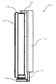
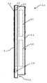
- FIG. 4 is a side view of the operation panel shown in FIG. 3. It is operation
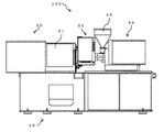
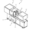
- the molding machine 100 of the present invention includes a mold opening / closing mechanism 20 and an injection mechanism on a machine base 10 having a substantially rectangular parallelepiped shape, and a schematic central portion on the front side (front side in FIG. 1) of the molding machine 100 on the machine base 10. And a door 21 that can be opened and closed, and a molding machine in which an operation panel 50 in which a display unit composed of a display panel 60 and an operation unit are integrated is arranged on the front side of the machine base 10 adjacent to the mold opening / closing mechanism 20.
- the operation panel 50 has a substantially rectangular shape in which short sides are arranged to face the vertical direction (up and down direction in FIG. 1) and long sides are arranged to face the horizontal direction (left and right direction in FIG. 1).
- the operation panel 50 generally has a generally thin box shape, and the generally thin box shape is composed of an adjacent front box portion 51 and a rear box portion 52,
- the horizontal dimension (width direction) of the front box part 51 and the rear box part 52 is substantially the same dimension
- the vertical dimension (height direction) of the front box part 51 and the rear box part 52 is
- the size of the front box portion 51 is larger than the size of the rear box portion 52, aligned at the upper portion, and adjacent to the lower portion of the front box portion 51 in a state where the front box portion 51 extends beyond the rear box portion 52.
- a step portion 53 is formed at the lower end portion.
- the horizontal dimension of the front box part 51 and the rear box part 52 is substantially the same dimension, but this does not need to be configured with exactly the same dimension as shown in FIG. This means that the dimensions are not positively made different.
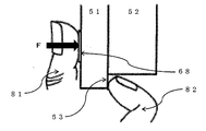
- the molding machine 100 forms a stepped portion 53 at the lower end (lower side in FIG. 3) of the operation panel 50, so that the operation panel is sandwiched between the thumb and the other four fingers from below. It is easy to operate.
- the display panel 60 of the operation panel 50 is disposed close to the pivot side of the one long side and the upper end side of the short side, and is long on the opposite side.
- a side frame 61 and a short frame 62 are provided.
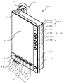
- the long frame 61 includes a plurality of device operation display units 63a and 63b, a plurality of mode selection buttons 64a to 64e, and a selection operation.
- An instruction button 66 is provided, and the short side frame portion 62 is provided with a page display light 67 and a plurality of operation selection hard switches 68 (68a, 68b to 68i, 68j).
- FIG. 1 is a front view of an injection molding machine according to an embodiment of the present invention
- FIG. 2 is a bird's eye perspective view thereof.
- 3 to 7 are diagrams showing details of the operation panel attached to the injection molding machine according to the embodiment of the present invention.
- An injection molding machine 100 is for injecting plastic or the like into a mold (not shown) and performing molding processing.
- a mold opening and closing is performed on the machine base 10 of the injection molding machine 100.
- a mechanism 20 and an injection unit 30 are provided on the machine base 10 of the injection molding machine 100.
- the mold opening / closing mechanism 20 includes a fixed mold (not shown) and a movable mold (not shown) that are opened and closed with each other, and is fixed by mold opening / closing means such as a conventional toggle mechanism (not shown). The movable mold is moved back and forth with respect to the mold to perform mold closing (clamping) and mold opening operations.
- FIG. 1 the machine base 10, the mold opening / closing mechanism 20 and the injection unit 30 are covered with a cover, and the detailed configuration of the internal mechanism is not drawn, but these are well-known configurations in the injection molding machine, It is not shown because it is not an essential feature of the invention.
- the injection unit 30 is provided with a heating cylinder 31, and a resin kneading screw (not shown) is provided in the heating cylinder 31.
- the tip of the heating cylinder 31 is provided with an assembled injection nozzle (not shown).
- the screw in the heating cylinder 31 is rotated using a driving force such as a motor (not shown) as a driving source to convey the molten resin while melting it, and the molten resin is conveyed from the tip of the injection nozzle to the fixed mold and the movable mold. Injection into the cavity formed by the mold.
- the details of the operation panel which is a characteristic part of the present invention are indicated by reference numeral 50 in FIGS. 3 to 7, and the operation panel 50 is disposed in the vicinity of the tip of the injection nozzle.
- the operation panel 50 has a vertically long rectangular shape (including a substantially rectangular shape) when viewed from the front, and is arranged such that the short sides face each other in the vertical direction and the long sides face each other in the horizontal direction.
- the operation panel 50 includes a large display panel 60 that displays the operating conditions and operating conditions of the injection molding machine 100.
- the display panel 60 is a liquid crystal display panel, for example, and is arranged vertically in this embodiment.
- the side frame section 62 is provided with a display section and an operation key group (a plurality of operation switches) to be described later for performing an operation by the operator.
- the long side frame body 61 on the other side of the vertically arranged display panel 60 has a plurality of device operation display units 63 (two in the figure, a motor drive display LED 63a and a heater operation display LED 63b) by LED blinking display,
- a plurality of mode selection buttons 64 as operation switches (five are shown, from the top, an injection molding machine off mode selection button 64a, a mold change mode selection button 64b, a manual mode selection button 64c, a semi-automatic mode selection button 64d, all An automatic mode selection button 64e) is provided.
- a selection operation instruction button 66 as an operation switch is provided at the lower end position of the long side frame body 61 on the other side of the display panel 60.
- the selection operation instruction button 66 cooperates with individual operation switches (soft switches) displayed in the display panel 60 according to the operation mode of the injection molding machine selected by the plurality of mode selection buttons 64 (64a to 64e). The operation of the injection molding machine is selected and executed by the operation.
- a short side frame body 62 on the lower side of the vertically arranged display panel 60 has a page display light 67 (LED) and a plurality of operation selection hard switches 68a, b; 68c, d; 68e, f; 68g, h; 68i, j (two pairs are shown in the figure, from left to right: mold opening / closing switch 68a, b, eject backward / forward switch 68c, d, injection / plasticizing switch 68e, f, nozzle touch Back switches 68g, h, mold thickness reverse / forward switches 68i, j) are provided.
- These operation selection hard switches 68a, b to 68i, j correspond to soft switches (not shown) displayed on the lower end portion of the display panel 60 and determine what operation is instructed. Yes, it is not limited to the types of operations described above.
- the page display light 67 notifies the operator that the display panel 60 is in the display state even if the backlight of the display panel 60 is turned off by turning on the LED.
- the plurality of operation selection hard switches (68a, b to 68i, j) correspond to a plurality of soft switches (not shown) displayed on the lower end of the display panel 60.
- the display / arrangement of the soft switch displayed on the display panel 60, the relationship with the operation selection hard switch, and the operation are not the problems to be solved by the present invention and will not be described in detail.
- the operation panel 50 is supported by a support bracket 70 that supports the operation panel 50 with respect to the injection molding machine 100 so as to be rotatable at least 90 ° in the horizontal direction (FIG. 5).
- the support bracket 70 of the operation panel 50 includes a support stem 71 that supports the operation panel 50 so as to sandwich the operation panel 50 from above and below, and the support stem 71 includes an upper support rod 72 that supports the operation panel 50 from above and a lower support that supports the operation panel 50 from below.
- a support member 73 is rotatably supported.
- the support stem 71 is attached to the frame of the injection molding machine 100 via an attachment member 74.
- the operation panel 50 includes a front box part 51 and a rear box part 52.
- the front box portion 51 and the rear box portion 52 may be integrally configured by pressing, or may be formed separately and joined. In that case, joining by welding or mechanical joining may be used.
- the operation panel 50 is provided with a cover glass 54 on the front surface, a touch panel 55 on the lower surface thereof, and a liquid crystal display unit 56 on the lower surface thereof to display appropriate charts, soft switches and the like at appropriate positions. Adjacent to the liquid crystal display unit 56 for displaying charts, soft switches, etc., the PC board 57 for controlling display, the input signal from the soft switch as the displayed input means, and the long side frame of the operation panel 50 An interface board 58 for taking in an input signal or the like from a hard switch provided in the part 61 and the short side frame part 62 is disposed. Below the liquid crystal display unit 56 of the front box 51, a selection operation instruction button 66 and a switch board 59 corresponding to a plurality of operation selection hard switches 68a, b to 68i, j are arranged.
- the front box portion 51 and the rear box portion 52 that constitute the operation panel 50 are configured such that the front box portion 51 is longer in the vertical direction than the rear box portion 52, thereby forming a step portion on the lower end side of the operation panel 50. 53 is formed. This is a characteristic matter of the present invention.
- the display panel 60 of the operation panel 50 is arranged close to one long side and the upper end side where the pivot is located, and the long side frame is placed on the opposite side.
- a body part 61 and a short side frame part 62 are provided.
- the long side frame part 61 has a plurality of device operation display parts 63a and 63b, a plurality of mode selection buttons 64a to 64e, and a selection operation instruction button 66.
- the short side frame 62 is provided with a page display light 67 and a plurality of operation selection hard switches 68a, 68b to 68i, 68j.
- a cover glass 54, a touch panel 55, a liquid crystal display unit 56, and a switch board 59 are arranged in the front box portion 51 of the operation panel 50.
- the rear box portion 52 is provided with a PC board 57 and an interface board 58, and the vertical dimension of the front box portion 51 is larger than the vertical dimension of the rear box portion.
- a stepped portion 53 is formed at the lower end of 50.
- the horizontal dimensions of the front box part 51 and the rear box part 52 are substantially the same, and the front box part 51 and the rear box part are the same.
- the vertical dimension of the part 52 is such that the size of the front box part 51 is larger than the dimension of the rear box part 52 and is aligned at the upper part and adjacent to the lower part in a state where the front box part 51 extends beyond the rear box part 52. Accordingly, a stepped portion 53 is formed at the lower end portion of the operation panel 50.
- the operation panel 50 is operated by being sandwiched from below the operation panel 50.
- the page display light 67 disposed in the short side frame portion 62 provided below the operation panel 50 the operation selection hard switches 68a, 68b to 68i, 68j, and the length provided on the side of the operation panel 50. It is easy to operate the selection operation instruction button 66 arranged at the lower end of the side frame portion 61 by pushing it with the thumb 81 from below the operation panel 50.
Landscapes
- Engineering & Computer Science (AREA)
- Manufacturing & Machinery (AREA)
- Mechanical Engineering (AREA)
- Injection Moulding Of Plastics Or The Like (AREA)
- Moulds For Moulding Plastics Or The Like (AREA)
Abstract
Le problème décrit par la présente invention est de fournir une machine de moulage dans laquelle : un mécanisme d'ouverture et de fermeture de moule et un mécanisme d'injection sont disposés sur une base de machine sensiblement cuboïde ; une porte capable de s'ouvrir et de se fermer est disposée sensiblement dans la partie centrale du côté avant de la machine de moulage, au-dessus de la base de la machine ; et un panneau de commande, dans lequel une partie de commande intégrée et une partie d'affichage comprenant un panneau d'affichage sont disposées sur le côté avant de la base de la machine, à côté du mécanisme d'ouverture et de fermeture du moule. La solution selon l'invention consiste en une machine de moulage dans laquelle : un panneau de commande est sensiblement cuboïde, le côté court de celui-ci étant disposé dans le sens vertical et le côté long de celui-ci étant disposé dans le sens horizontal ; le panneau de commande est disposé de façon à pouvoir tourner dans le sens horizontal, tout en maintenant une orientation verticale autour d'une partie de pivot sur un côté long de celui-ci ; le panneau de commande se présente sous la forme d'un boîtier sensiblement mince, et la forme de boîtier sensiblement mince comprend une partie de boîtier avant et une partie de boîtier arrière, adjacentes l'une à l'autre ; les dimensions dans le sens horizontal de la partie de boîtier avant et de la partie de boîtier arrière sont sensiblement identiques ; les dimensions dans le sens vertical de la partie de boîtier avant et de la partie de boîtier arrière sont telles que la dimension de la partie de boîtier avant est plus grande que la dimension de la partie de boîtier arrière ; en conséquence du fait que la partie de boîtier avant soit adjacente à la partie de boîtier arrière et s'étende plus loin que la partie de boîtier arrière au niveau de la partie inférieure, une marche est formée au niveau de la partie d'extrémité inférieure du panneau de commande.
Priority Applications (2)
| Application Number | Priority Date | Filing Date | Title |
|---|---|---|---|
| CN201780033557.7A CN109195767A (zh) | 2016-05-31 | 2017-05-31 | 成型机以及操作板 |
| JP2018520945A JP6805247B2 (ja) | 2016-05-31 | 2017-05-31 | 成形機および操作盤 |
Applications Claiming Priority (2)
| Application Number | Priority Date | Filing Date | Title |
|---|---|---|---|
| JP2016-109127 | 2016-05-31 | ||
| JP2016109127 | 2016-05-31 |
Publications (1)
| Publication Number | Publication Date |
|---|---|
| WO2017209163A1 true WO2017209163A1 (fr) | 2017-12-07 |
Family
ID=60477508
Family Applications (1)
| Application Number | Title | Priority Date | Filing Date |
|---|---|---|---|
| PCT/JP2017/020193 Ceased WO2017209163A1 (fr) | 2016-05-31 | 2017-05-31 | Machine de moulage et panneau de commande |
Country Status (3)
| Country | Link |
|---|---|
| JP (1) | JP6805247B2 (fr) |
| CN (1) | CN109195767A (fr) |
| WO (1) | WO2017209163A1 (fr) |
Families Citing this family (2)
| Publication number | Priority date | Publication date | Assignee | Title |
|---|---|---|---|---|
| CN112453089A (zh) * | 2020-11-02 | 2021-03-09 | 西安谢赫特曼诺奖新材料研究院有限公司 | 一种应用于高强度镁合金原材料加工的棒材成型装置 |
| CN116330575A (zh) * | 2023-03-20 | 2023-06-27 | 佛山市顺德区震德精密机械有限公司 | 一种射出成型机 |
Citations (6)
| Publication number | Priority date | Publication date | Assignee | Title |
|---|---|---|---|---|
| JPH02106316U (fr) * | 1989-02-13 | 1990-08-23 | ||
| JPH068299A (ja) * | 1993-02-08 | 1994-01-18 | Fanuc Ltd | 計量・混練条件をグラフ表示する射出成形機 |
| JPH07232363A (ja) * | 1994-02-24 | 1995-09-05 | Fanuc Ltd | 表示装置を備えた射出成形機 |
| JP2003231030A (ja) * | 2002-02-14 | 2003-08-19 | Eguro:Kk | 跳ね上げ式操作盤およびそれを用いたnc旋盤 |
| JP2004100819A (ja) * | 2002-09-09 | 2004-04-02 | Toshiba Mach Co Ltd | 弾力性部材で被覆形成した機械構成部材を有する成形機及びその被覆形成方法ならびに同方法により製造された機械構成部材および産業機械および構造体 |
| JP2008272872A (ja) * | 2007-04-27 | 2008-11-13 | Toyo Mach & Metal Co Ltd | 工作機の操作盤及び射出成形機の操作盤 |
Family Cites Families (3)
| Publication number | Priority date | Publication date | Assignee | Title |
|---|---|---|---|---|
| CN2696814Y (zh) * | 2004-04-01 | 2005-05-04 | 胡惠昌 | 大型注塑机的按钮箱 |
| JP5391856B2 (ja) * | 2008-07-23 | 2014-01-15 | 株式会社リコー | パネル支持装置およびパネル支持装置を用いた装置 |
| CN204149480U (zh) * | 2014-09-07 | 2015-02-11 | 宁波鑫星汽车部件有限公司 | 一种防辐射注塑机装置 |
-
2017
- 2017-05-31 JP JP2018520945A patent/JP6805247B2/ja active Active
- 2017-05-31 WO PCT/JP2017/020193 patent/WO2017209163A1/fr not_active Ceased
- 2017-05-31 CN CN201780033557.7A patent/CN109195767A/zh active Pending
Patent Citations (6)
| Publication number | Priority date | Publication date | Assignee | Title |
|---|---|---|---|---|
| JPH02106316U (fr) * | 1989-02-13 | 1990-08-23 | ||
| JPH068299A (ja) * | 1993-02-08 | 1994-01-18 | Fanuc Ltd | 計量・混練条件をグラフ表示する射出成形機 |
| JPH07232363A (ja) * | 1994-02-24 | 1995-09-05 | Fanuc Ltd | 表示装置を備えた射出成形機 |
| JP2003231030A (ja) * | 2002-02-14 | 2003-08-19 | Eguro:Kk | 跳ね上げ式操作盤およびそれを用いたnc旋盤 |
| JP2004100819A (ja) * | 2002-09-09 | 2004-04-02 | Toshiba Mach Co Ltd | 弾力性部材で被覆形成した機械構成部材を有する成形機及びその被覆形成方法ならびに同方法により製造された機械構成部材および産業機械および構造体 |
| JP2008272872A (ja) * | 2007-04-27 | 2008-11-13 | Toyo Mach & Metal Co Ltd | 工作機の操作盤及び射出成形機の操作盤 |
Also Published As
| Publication number | Publication date |
|---|---|
| CN109195767A (zh) | 2019-01-11 |
| JP6805247B2 (ja) | 2020-12-23 |
| JPWO2017209163A1 (ja) | 2019-04-25 |
Similar Documents
| Publication | Publication Date | Title |
|---|---|---|
| JP5401079B2 (ja) | 射出成形機 | |
| KR101192376B1 (ko) | 판체를 갖는 사출물 절단장치 | |
| JP2011121310A (ja) | 射出成形機 | |
| JP6805247B2 (ja) | 成形機および操作盤 | |
| WO2020195680A1 (fr) | Fonction d'affichage de prévisualisation pour le fonctionnement d'une machine de moulage par injection | |
| CN108136641B (zh) | 具有至少一个摄像机的塑料注射成型机 | |
| US20250355553A1 (en) | Molding machine | |
| CN104943054B (zh) | 注射成型机 | |
| JP2006305814A (ja) | 射出成形機の制御装置 | |
| US5520528A (en) | Molding machine having hand operated control | |
| JP2006289911A (ja) | 射出成形機の制御装置 | |
| JP2025015819A (ja) | 加熱筒交換治具および竪型射出成形機の加熱筒交換方法 | |
| JP4972485B2 (ja) | 燈体の製造装置 | |
| JP6300350B2 (ja) | 樹脂成形品取出し機におけるゲート切断位置データ設定方法及び樹脂成形品取出し機 | |
| JP2017213839A (ja) | 射出成型機 | |
| JP5451021B2 (ja) | 射出成形機の制御方法 | |
| JP6774777B2 (ja) | 表示操作装置および成形機 | |
| TWM452174U (zh) | 用來製造模造玻璃之成型設備 | |
| JP7114437B2 (ja) | 射出成形機および射出成形方法 | |
| CN106863726B (zh) | 注射成型机 | |
| CN101486235B (zh) | 旋转式滑块装置及应用该滑块装置的塑胶注塑模具 | |
| JP3142059U (ja) | 射出成形機の監視装置 | |
| US20250044927A1 (en) | Data display device and molding machine | |
| JP6603843B1 (ja) | 射出成形装置、および射出成形装置制御プログラム | |
| JP2025066856A (ja) | 射出成形機 |
Legal Events
| Date | Code | Title | Description |
|---|---|---|---|
| WWE | Wipo information: entry into national phase |
Ref document number: 2018520945 Country of ref document: JP |
|
| 121 | Ep: the epo has been informed by wipo that ep was designated in this application |
Ref document number: 17806715 Country of ref document: EP Kind code of ref document: A1 |
|
| NENP | Non-entry into the national phase |
Ref country code: DE |
|
| 122 | Ep: pct application non-entry in european phase |
Ref document number: 17806715 Country of ref document: EP Kind code of ref document: A1 |