WO2017209189A1 - Rétracteur de ceinture de sécurité et système de ceinture de sécurité - Google Patents
Rétracteur de ceinture de sécurité et système de ceinture de sécurité Download PDFInfo
- Publication number
- WO2017209189A1 WO2017209189A1 PCT/JP2017/020291 JP2017020291W WO2017209189A1 WO 2017209189 A1 WO2017209189 A1 WO 2017209189A1 JP 2017020291 W JP2017020291 W JP 2017020291W WO 2017209189 A1 WO2017209189 A1 WO 2017209189A1
- Authority
- WO
- WIPO (PCT)
- Prior art keywords
- rotation
- seat belt
- spool
- magnet
- detection unit
- Prior art date
- Legal status (The legal status is an assumption and is not a legal conclusion. Google has not performed a legal analysis and makes no representation as to the accuracy of the status listed.)
- Ceased
Links
Images




Classifications
-
- B—PERFORMING OPERATIONS; TRANSPORTING
- B60—VEHICLES IN GENERAL
- B60R—VEHICLES, VEHICLE FITTINGS, OR VEHICLE PARTS, NOT OTHERWISE PROVIDED FOR
- B60R22/00—Safety belts or body harnesses in vehicles
- B60R22/48—Control systems, alarms, or interlock systems, for the correct application of the belt or harness
Definitions
- the present invention relates to a seat belt retractor and a seat belt system.
- a webbing take-up shaft comprising a webbing take-up shaft, a spring spring having one end connected to the take-up shaft, and a spring holding box that is rotatably supported while the other end of the spring spring is locked.
- An apparatus is known (see, for example, Patent Document 1).
- This webbing take-up device detects the rotation direction of the take-up shaft and the rotation position of the spring holding box, and rotates the spring holding box with a motor to change the setting position of the spring spring, so that the winding biasing force by the main spring is used. To adjust.
- the tension of the seatbelt by the mainspring changes depending on how much the winding shaft rotates with respect to the spring holding box. Therefore, it is difficult to adjust the tension of the seat belt with high accuracy unless the amounts of rotation of the winding shaft and the spring holding box are known when the spring holding box is rotated by a motor.
- an aspect of the present disclosure is intended to provide a seat belt retractor and a seat belt system that can adjust the tension of the seat belt with high accuracy.
- a spool that winds up the seat belt One end connected to the rotating shaft of the spool, and a spiral spring that urges the spool in the winding direction of the seat belt;
- a spring case connected to the other end of the spiral spring and rotatably provided around the rotation axis;
- the spring case is rotated according to a difference between a rotation amount of the spool whose rotation is detected by the first rotation detection unit and a rotation amount of the spring case whose rotation is detected by the second rotation detection unit.
- a seat belt system includes the seat belt retractor and a control device that controls driving of the motor according to the difference.
- the tension of the seat belt can be adjusted with high accuracy.
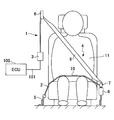
- FIG. 1 is a diagram illustrating an example of a configuration of a seat belt system 1 according to an embodiment.
- the seat belt system 1 is an example of a system mounted on a vehicle.
- the seat belt system 1 includes, for example, a seat belt 4, a retractor 3, a shoulder anchor 6, a tongue 7, a buckle 8, and an ECU (Electronic Control Unit) 100.
- ECU Electronic Control Unit
- the seat belt 4 is an example of a webbing that restrains the occupant 11 sitting on the seat 2 of the vehicle, and is a belt-like member that is wound around the retractor 3 so that it can be pulled out.
- the belt anchor 5 at the tip of the seat belt 4 is fixed to the floor of the vehicle body or the seat 2.
- the retractor 3 is an example of a take-up device that enables the seat belt 4 to be taken up or pulled out. When an acceleration / deceleration or a vehicle angle of a predetermined value or more at the time of a vehicle collision or the like is detected, the seat belt 4 is retracted. To be drawn from.
- the retractor 3 is fixed to the seat 2 or a vehicle body near the seat 2.
- the retractor 3 is an example of a seat belt retractor.
- the retractor 3 winds the seat belt 4 around the spool by the power of the motor.
- the retractor 3 operates a motor based on a signal from a sensor such as a millimeter wave radar to wind the seat belt 4 around a spool before the vehicle collides, and applies a pretension to the seat belt 4 to restrain the passenger by the seat belt 4. Do it quickly.
- the retractor 3 operates the motor when the engagement between the tongue 7 and the buckle 8 is released, and winds up the seat belt 4 with the spool. Further, the retractor 3 operates the motor to adjust the tension of the seat belt 4 in accordance with the driving situation (the state of the vehicle), thereby restraining the occupant by the seat belt 4 and comfort when the seat belt 4 is worn. Improve each.
- the shoulder anchor 6 is an example of a belt insertion tool through which the seat belt 4 is inserted, and is a member that guides the seat belt 4 pulled out from the retractor 3 toward the shoulder of the occupant 11.
- the tongue 7 is an example of a belt insertion tool through which the seat belt 4 is inserted, and is a component that is slidably attached to the seat belt 4 guided by the shoulder anchor 6.
- the buckle 8 is a part to which the tongue 7 is detachably connected, and is fixed to the floor of the vehicle body or the seat 2, for example.
- the portion of the seat belt 4 between the shoulder anchor 6 and the tongue 7 is a shoulder belt portion 9 that restrains the chest and shoulder portions of the occupant 11.
- the portion of the seat belt 4 between the belt anchor 5 and the tongue 7 is a lap belt portion 10 that restrains the waist of the occupant 11.
- the ECU 100 is an example of a control device connected via one or a plurality of wire harnesses 101 so as to be communicable with the retractor 3.
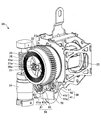
- FIG. 2 is a perspective view showing an example of the configuration of the retractor 3A.
- the retractor 3A is a first example of the retractor 3 shown in FIG.
- the retractor 3 ⁇ / b> A includes, for example, a frame 19, a spool 20 that is rotatably supported by the frame 19 and winds up the seat belt 4, a retainer 16 fixed to the frame 19, and a cover attached to the retainer 16.
- the frame 19 includes a frame plate 18 and a base frame 17.
- the retainer 16 and the frame plate 18 are fixed to the base frame 17.
- the spool 20 is rotatably supported by the base frame 17.
- FIG. 3 is a perspective view showing an example of a configuration of the retractor 3A with a part thereof omitted.
- FIG. 4 is a front view showing an example of a configuration of the retractor 3A with a part thereof omitted.
- FIG. 5 is a side view showing an example of a configuration of the retractor 3A with a part thereof omitted.
- FIG. 6 is an exploded perspective view showing an example of a configuration of the retractor 3A with a part thereof omitted.
- the retractor 3 ⁇ / b> A includes a spool 20, a spiral spring 22, a spring case 23, a first rotating disk 38, a first rotation detecting unit 40, a second rotating disk 58, and a second rotation detecting unit 60. And an arithmetic unit 73 and a motor 24.
- the spool 20 is a rotating member that winds up the seat belt 4.
- the rotating shaft of the spool 20 includes a shaft 20a and a bush 21 fixed to one end of the shaft 20a.
- the spiral spring 22 has one end 22 a connected to the rotating shaft of the spool 20 and the other end connected to the outer peripheral wall of the spring case 23, and elastically urges the spool 20 in the winding direction of the seat belt 4. It is an example of a body.
- One end 22a of the spiral spring 22 is connected to a bush 21 attached to the spool 20 so as to be integrally rotatable, and the spool 20 is constantly urged in the winding direction of the seat belt 4.
- One end 22 a of the spiral spring 22 is hooked in a groove 21 a formed in the bush 21.
- the spring case 23 has an outer peripheral wall to which the other end of the spiral spring 22 is connected, and accommodates the spiral spring 22 inside the outer peripheral wall.
- the spring case 23 is provided so as to be rotatable with respect to the frame plate 18 (see FIG. 2) of the frame 19 around the rotation axis of the spool 20. That is, the spring case 23 is provided so as to be rotatable coaxially with the rotation axis of the spool 20.
- External teeth 23 a are formed on the outer peripheral wall of the spring case 23.
- the first rotary disk 38 is attached to the frame plate 18 so as to be rotatable.
- the first rotating disk 38 includes an annular first magnet holding member 42 and a first magnet 41 that is integrally rotatable with the first magnet holding member 42 and arranged in an annular shape.
- the annular first magnet 41 is formed by alternately arranging N-pole magnets 41 a and S-pole magnets 41 b in the circumferential direction of the first magnet 41.
- the magnetization width of the N-pole magnet 41 a is set to a predetermined first angular width in the circumferential direction of the first magnet 41, and the magnetization width of the S-pole magnet 41 b is the circumference of the first magnet 41.
- a predetermined second angular width is set in the direction.
- the second angular width may be the same as or different from the first angular width.
- the first magnet holding member 42 integrally has a cylindrical first driven gear 43 having external teeth 43 a (see FIG. 5) arranged concentrically with the first magnet holding member 42. . As the first driven gear 43 rotates, the first magnet 41 rotates together with the first driven gear 43 coaxially with the rotation shaft of the first driven gear 43.
- a transmission gear 44 is attached to the shaft 20a of the rotating shaft of the spool 20 so as to be rotatable integrally with the shaft 20a.
- External teeth 44 a are formed on the outer periphery of the transmission gear 44.
- the external teeth 43 a of the first driven gear 43 mesh with the external teeth 44 a of the transmission gear 44.
- the first rotation detection unit 40 is an example of a rotation detection unit that detects the rotation of the spool 20.
- the first rotation detection unit 40 detects the rotation of the spool 20 by detecting the rotation of the first magnet 41.
- the first rotation detection unit 40 includes, for example, a first magnetic detection unit 40a and a second magnetic detection unit 40b.
- the first magnetic detection unit 40 a and the second magnetic detection unit 40 b detect the strength of the magnetic field (magnetic field) that changes as the first magnet 41 rotates.
- a specific example of the first magnetic detection unit 40a and the second magnetic detection unit 40b is a Hall element.
- the Hall element is an example of a semiconductor element that detects a magnetic change by the Hall effect.
- the transmission gear 44 that rotates integrally with the rotation shaft of the spool 20 rotates.
- the first driven gear 43 formed with the outer teeth 43a meshing with the outer teeth 44a of the transmission gear 44 rotates, so that the first magnet 41 of the first rotating disk 38 is rotated. Rotate. That is, when the spool 20 rotates in the seat belt 4 pull-out direction, the first magnet 41 rotates in a rotation direction corresponding to the seat belt 4 pull-out direction in conjunction with the rotation of the spool 20.
- the first magnetic detection unit 40a and the second magnetic detection unit 40b respectively detect the N-pole magnet 41a and the S-pole magnet 41b.
- a detection signal whose phase is inverted is output.
- the amplitude of the detection signal is proportional to the strength of the detected magnetic field, for example.
- the phase of the detection signal output from the first magnetic detection unit 40a is the second magnetic detection unit.
- the phase of the detection signal output from the unit 40b is shifted by a predetermined amount.
- the calculation unit 73 detects the rotation amount (rotation position) of the spool 20 by counting the number of phase inversions of the detection signal output from each of the first magnetic detection unit 40a and the second magnetic detection unit 40b. To do. In addition, the calculation unit 73 rotates the spool 20 based on the phase shift between the detection signal output from the first magnetic detection unit 40a and the detection signal output from the second magnetic detection unit 40b. It is determined whether the direction is the pulling direction of the seat belt 4 or the winding direction of the seat belt 4.
- the second rotating disk 58 is rotatably attached to the frame plate 18.
- the second rotating disk 58 includes an annular second magnet holding member 62 and a second magnet 61 arranged in an annular shape so as to be rotatable integrally with the second magnet holding member 62. Yes.
- the annular second magnet 61 is formed by alternately arranging N-pole magnets 61 a and S-pole magnets 61 b in the circumferential direction of the second magnet 61.
- the magnetization width of the N-pole magnet 61 a is set to a predetermined third angular width in the circumferential direction of the second magnet 61, and the magnetization width of the S-pole magnet 61 b is the circumference of the second magnet 61.
- a predetermined fourth angular width is set in the direction.
- the fourth angular width may be the same as or different from the third angular width.
- the second magnet holding member 62 integrally includes a cylindrical second driven gear 63 having external teeth 63 a disposed concentrically with the second magnet holding member 62. As the second driven gear 63 rotates, the second magnet 61 rotates coaxially with the rotation axis of the second driven gear 63 together with the second driven gear 63.
- the external teeth 63a of the second driven gear 63 mesh with the external teeth 23a of the spring case 23.
- the second rotation detector 60 is an example of a rotation detector that detects the rotation of the spring case 23.
- the second rotation detection unit 60 detects the rotation of the spring case 23 by detecting the rotation of the second magnet 61.
- the second rotation detection unit 60 includes, for example, a third magnetic detection unit 60a and a fourth magnetic detection unit 60b.
- the third magnetic detection unit 60 a and the fourth magnetic detection unit 60 b detect the strength of the magnetic field (magnetic field) that changes as the second magnet 61 rotates.
- Specific examples of the third magnetic detection unit 60a and the fourth magnetic detection unit 60b include Hall elements.
- the Hall element is an example of a semiconductor element that detects a magnetic change by the Hall effect.
- the third magnetic detection unit 60a and the fourth magnetic detection unit 60b respectively detect the N-pole magnet 61a and the S-pole magnet 61b.
- a detection signal whose phase is inverted is output.
- the amplitude of the detection signal is proportional to the strength of the detected magnetic field, for example.
- the phase of the detection signal output from the third magnetic detector 60a is the fourth magnetic detection.
- the phase of the detection signal output from the unit 60b is shifted by a predetermined amount.
- the calculation unit 73 counts the number of inversions of the phase of the detection signal output from each of the third magnetic detection unit 60a and the fourth magnetic detection unit 60b, thereby calculating the rotation amount (rotation position) of the spring case 23. Detect. In addition, the calculation unit 73 determines whether the spring case 23 has a phase shift between the detection signal output from the third magnetic detection unit 60a and the detection signal output from the fourth magnetic detection unit 60b. It is determined whether the rotation direction is the pulling direction of the seat belt 4 or the winding direction of the seat belt 4.
- the calculation unit 73 calculates a difference between the rotation amount of the spool 20 whose rotation is detected by the first rotation detection unit 40 and the rotation amount of the spring case 23 whose rotation is detected by the second rotation detection unit 60 (hereinafter, referred to as “rotation amount”). (Referred to as difference D), and the calculation result of difference D is output.
- rotation amount a difference between the rotation amount of the spool 20 whose rotation is detected by the first rotation detection unit 40 and the rotation amount of the spring case 23 whose rotation is detected by the second rotation detection unit 60 (hereinafter, referred to as “rotation amount”).
- difference D the calculation result of difference D is output.
- Specific examples of the calculation unit 73 include a microcomputer, an ASIC (Application Specific Integrated Circuit), and an FPGA (Field Programmable Gate Array).
- ECU100 acquires the calculation result of the difference D obtained by the calculating part 73 via the wire harness 101.
- FIG. The ECU 100 controls the driving of the motor 24 according to the obtained calculation result of the difference D.
- the ECU 100 includes a processor such as a CPU (Central Processing ⁇ ⁇ Unit) and a memory.
- Each function of ECU 100 (such as a function for controlling driving of motor 24) is realized by a program processed by the processor. Programs for realizing these functions are stored in the memory.
- the ECU 100 controls the driving of the motor 24 in this way, so that the motor 24 rotates the spring case 23 according to the difference D.
- the tension of the seat belt 4 changes (for example, increases). Therefore, when the motor 24 rotates the spring case 23 according to the difference D, the motor 24 can adjust the tension of the seat belt 4 continuously and continuously with high accuracy.
- ECU100 controls the drive of the motor 24, for example so that the difference D may correspond to a predetermined target value.
- the motor 24 rotates the spring case 23 so that the difference D matches a predetermined target value.
- the motor 24 can adjust the tension of the seat belt 4 to a predetermined target tension value with high accuracy.
- the ECU 100 may control the driving of the motor 24 so that a change amount (hereinafter referred to as a change amount A) that changes according to the difference D matches a predetermined target value.
- a change amount A a change amount that changes according to the difference D matches a predetermined target value.
- the motor 24 rotates the spring case 23 so that the change amount A matches a predetermined target value. Accordingly, the motor 24 can adjust the tension of the seat belt 4 to a predetermined target tension value with high accuracy.
- change amount A include the tension of the seat belt 4 and the winding force of the seat belt 4 by the spiral spring 22.
- the ECU100 controls the drive of the motor 24, for example so that the difference D or the variation
- the ECU 100 drives the motor 24 to move the spring case 23 in the direction in which the seat belt 4 is pulled out.
- the same amount of rotation can be rotated. Therefore, even when the seat belt 4 is pulled out, the tension of the spiral spring 22 in the winding direction of the seat belt 4 can be suppressed and the tension of the seat belt 4 can be kept constant at all times.
- the ECU 100 drives the motor case 24 to move the spring case 23 in the direction in which the seat belt 4 is pulled out from the amount of rotation.
- a large amount of rotation can be rotated.
- the ECU 100 increases or decreases the tension of the seat belt 4 by keeping the urging force of the spiral spring 22 from rising in the seat belt 4 winding direction in accordance with the amount of the seat belt 4 pulled out. it can. As a result, the wearing operation of the seat belt 4 becomes light.
- the amount of the seat belt withdrawn increases, the amount of winding of the spring spring also increases uniformly, so that the tension of the seat belt 4 becomes higher. As a result, the wearing operation of the seat belt 4 becomes heavy.
- the ECU 100 can freely adjust the tension of the seat belt 4 according to the difference D while the seat belt 4 is worn after the tongue 7 and the buckle 8 are connected. Therefore, the ECU 100 can reduce the feeling of pressure applied to the occupant 11 when the seat belt 4 is worn by reducing the tension of the seat belt 4 according to the difference D.
- ECU100 may control the drive of the motor 24, for example so that the difference D or the variation
- the motor 24 rotates the spring case 23 so that the difference D or the change amount A matches the target value set according to the state of the vehicle.
- the motor 24 can adjust the tension of the seat belt 4 to a target tension value suitable for each state of the vehicle with high accuracy.
- the state of the vehicle includes, for example, whether or not the seat belt 4 is pulled out, whether or not the occupant 11 is present, traveling speed of the vehicle, acceleration of the vehicle, steering operation, accelerator operation, brake operation, operation of the buckle 8, door operation, and operation by the occupant This refers to a state that represents a possible operation input of an on-vehicle selection switch.
- the ECU 100 controls the driving of the motor 24 so that the difference D or the change amount A matches the target value set according to the traveling speed and / or acceleration of the vehicle.
- the ECU 100 can increase the tension of the seat belt 4 as the traveling speed and / or acceleration of the vehicle increases. Therefore, the posture retention of the occupant 11 is improved.
- the ECU 100 may control the driving of the motor 24 so that the difference D or the change amount A matches the target value set according to the operation of the occupant.
- the passenger can set the tension of the seat belt 4 to a desired tension by manual operation using a dial, a switch, or the like or by voice operation.
- the ECU 100 increases the tension of the seat belt 4 according to the difference D until the seat belt 4 is stored in the retractor 3 when the connection between the tongue 7 and the buckle 8 is released. Can be improved.
- the spring case 23 in which the external teeth 23a are formed functions as a worm wheel.
- the motor 24 rotates the spring case 23 via a worm 25 that meshes with the external teeth 23a.
- the external teeth 23 a rotate the worm 25 for rotating the spring case 23 and the second magnet 61 for rotating the second magnet 61 so that the second rotation detector 60 detects the rotation of the spring case 23. It meshes with both the transmission gear 63.
- the gear for detecting the rotation of the spring case 23 and the gear for driving the rotation of the spring case 23 are shared as the external teeth 23a. By sharing the gear, it is possible to reduce the size and cost.
- the worm 25 may have a lead angle capable of self-locking. Thereby, transmission of rotation from the spring case 23 to the worm 25 can be suppressed. Therefore, the ECU 100 can maintain the urging force of the spiral spring 22 in the winding direction of the seat belt 4 even when the motor 24 is not energized. As a result, it is possible to reduce the power consumed by the motor 24 during the period when the tension of the seat belt 4 is not required to be adjusted.
- the retractor 3 ⁇ / b> A has a substrate 70.
- the substrate 70 includes a first rotation detection unit 40, a second rotation detection unit 60, and a calculation unit 73. Since the first rotation detection unit 40, the second rotation detection unit 60, and the calculation unit 73 are arranged on a common board 70, the number of components can be reduced.
- the ECU 100 acquires the detection signals output from the first rotation detection unit 40 and the second rotation detection unit 60 via the wire harness 101 and the ECU 100 calculates the difference D is conceivable.
- the wire harness 101 for transmitting the detection signal output from the first rotation detection unit 40 to the ECU 100 and the detection signal output from the second rotation detection unit 60 are transmitted to the ECU 100.
- the wire harness 101 is required separately.
- the calculation unit 73 outputs a signal corresponding to the calculation result of the difference D to the ECU 100 via the wire harness 101. Therefore, the number of wire harnesses 101 can be reduced as compared with the above-described embodiment in which separate wire harnesses 101 are necessary for transmitting the detection signals.
- the substrate 70 is disposed between the spool 20 and the spring case 23.
- the substrate 70 has a first substrate surface on the spool 20 side and a second substrate surface on the spring case 23 side (the opposite side to the first substrate surface). Since the first rotation detection unit 40 is disposed on the surface of the first substrate and the second rotation detection unit 60 is disposed on the surface of the second substrate, the two rotation bodies of the spool 20 and the spring case 23 are arranged. The rotation detection can be realized on one common substrate 70.
- the first rotation detector 40 On the surface of the first substrate, the first rotation detector 40 is arranged so as to face the first magnet 41 of the first rotating disk 38. On the surface of the second substrate, the second rotation detector 60 is disposed so as to face the second magnet 61 of the second rotating disk 58. Since the magnet and the rotation detection unit are arranged to face each other, the rotation detection accuracy is improved.
- FIG. 7 is a diagram showing an example of the configuration of the retractor 3B.
- the retractor 3B is a second example of the retractor 3 shown in FIG. Of the configuration and effect of the retractor 3B, the description of the same configuration and effect as the retractor 3A is omitted by using the above description.
- the first rotation detection unit 40 and the second rotation detection unit 60 are mounted on a common substrate 70.
- the first rotation detection unit 40 and the second rotation detection unit 60 are mounted on separate substrates.
- the first rotation detection unit 40 is mounted on the substrate 71.
- the second rotation detection unit 60 is mounted on the substrate 72.
- the computing unit 73 is mounted on the substrate 71 or the substrate 72.
- the calculation unit 73 may be mounted on a board different from the boards 71 and 72.
- FIG. 8 is a front view showing an example of the configuration of the retractor 3C.
- FIG. 9 is a side view showing an example of the configuration of the retractor 3C.
- the description of the same configuration and effect as the retractor 3A is omitted or simplified by using the above description.
- the retractor 3 ⁇ / b> C includes a spool 20 that winds up the seat belt, a substrate case 180 that accommodates the substrate 170, a retainer 116 that is fixed to the base frame 17 together with the substrate case 180, and a cover 115 that is attached to the retainer 116.
- the retainer 116 covers part or all of the substrate 170 between the substrate case 180 and the retainer 116.
- a substrate 170 and a substrate case 180 are sandwiched between the retainer 116 and the base frame 17.
- the worm 25 is rotated by the motor 24.
- a worm cover 26 that houses the worm 25 is fixed to the retainer 116.
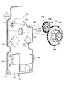
- FIG. 10 is an exploded perspective view showing an example of the configuration of the retractor 3C with a part thereof omitted.
- illustration of the spiral spring 22 housed in the spring case 23 and the cover 115 covering the spiral spring 22 is omitted to improve the visibility of the drawing.
- the retractor 3C includes a substrate 170.
- the substrate 170 is disposed between the spool 20 and the spring case 23, and is disposed between the substrate case 180 and the retainer 116.
- the substrate 170 has a first substrate surface 171 on the spool 20 side and a second substrate surface 172 on the spring case 23 side (opposite side to the first substrate surface).
- the first rotation detector 40 is disposed on the first substrate surface 171
- the second rotation detector 60 is disposed on the second substrate surface 172. Therefore, the rotation detection of the two rotating bodies of the spool 20 and the spring case 23 can be realized on one common substrate 170.
- the retractor 3 ⁇ / b> C includes a first magnet 141 and a second magnet 161.
- the first magnet 141 rotates with the rotation of the spool 20 at an axis different from that of the spool 20.
- the second magnet 161 rotates on the same axis as the spool 20 as the spring case 23 rotates.
- FIG. 11 is a perspective view showing an example of the positional relationship between the first rotation detector and the first magnet.
- the transmission gear 144 rotates on the same axis 151 as the spool 20 as the spool 20 rotates.
- the axis 151 represents the rotation axis center of the shaft 20 a of the spool 20.
- the shaft 20 a is fitted in a central hole 144 b formed in the transmission gear 144.
- the transmission gear 144 that rotates integrally with the shaft 20a and concentrically rotates.
- the driven gear 143 formed with the outer teeth 143a meshing with the outer teeth 144a of the transmission gear 144 rotates.
- the driven gear 143 has an annular first magnet 141 fitted inside the external teeth 143a. Therefore, when the driven gear 143 rotates, the first magnet 141 also rotates.
- the shaft center 152 represents the center of the protruding shaft 184 (see FIG. 10), which is the rotation shaft of the driven gear 143.
- the protruding shaft 184 protrudes from the surface of the substrate case 180 on the spool 20 side.
- the protruding shaft 184 is fitted into a central hole 143 b formed in the driven gear 143.
- the first magnet 141 is formed by alternately arranging N-pole magnets 141 a and S-pole magnets 141 b in the circumferential direction of the first magnet 141.
- the magnetization width of the N-pole magnet 141 a is set to a predetermined first angular width in the circumferential direction of the first magnet 141
- the magnetization width of the S-pole magnet 141 b is the circumference of the first magnet 41.
- a predetermined second angular width is set in the direction. The second angular width may be the same as or different from the first angular width.
- FIG. 12 is a perspective view showing an example of the positional relationship between the second rotation detector and the second magnet.
- the second magnet 161 has the same axis 151 as the spool 20 and rotates as the spring case 23 rotates.
- the axis 151 represents the rotation axis center of the shaft 20 a of the spool 20.
- the second magnet 161 is attached to the bottom surface 23b of the spring case 23 on the substrate 70 side.
- the shaft 20 a passes through the substrate hole 173 formed in the substrate 170 and the annular second magnet 161 and is fitted into the spring case 23. Therefore, the second magnet 161 rotates with the rotation of the spring case 23 at the same axis 151 as the spool 20.
- the second magnet 161 is formed by alternately arranging N-pole magnets 161 a and S-pole magnets 161 b in the circumferential direction of the second magnet 161.
- the magnetization width of the N-pole magnet 161 a is set to a predetermined third angular width in the circumferential direction of the second magnet 161
- the magnetization width of the S-pole magnet 161 b is the circumference of the second magnet 161.
- a predetermined fourth angular width is set in the direction.
- the fourth angular width may be the same as or different from the third angular width.
- the first rotation detection unit 40 can detect the rotation of the spool 20 by detecting the strength of the magnetic field that changes due to the rotation of the first magnet 141.
- the second rotation detection unit 60 can detect the rotation of the spring case 23 by detecting the strength of the magnetic field that changes as the second magnet 161 rotates.
- the first magnet 141 rotates with an axis 152 different from that of the spool 20, and the second magnet 161 rotates with the same axis 151 as the spool 20.
- the magnetic field by the 1st magnet 141 interferes with the magnetic detection parts 60a and 60b of the 2nd rotation detection part 60, and the magnetic field by the 2nd magnet 161 is the 1st rotation detection part 40. Interference with the magnetic detectors 40a and 40b is suppressed. As a result, it is possible to prevent a decrease in accuracy of rotation detection.
- the shaft 20 a passes through a case hole 181 formed in the substrate case 180, a substrate hole 173 formed in the substrate 170, and a retainer hole 116 a formed in the retainer 116.
- the boss 182 protruding from the surface of the substrate case 180 on the substrate 170 side is inserted into a positioning hole 175 formed in the substrate 170.
- the boss 182 is concentric with the protruding shaft 184. Therefore, when the boss 182 is inserted into the positioning hole 175, the first rotation detection unit 40 disposed on the first substrate surface 171 of the substrate 170 and the first magnet 141 that rotates around the protruding shaft 184. Can be reduced.
- the first rotation detection unit 40 detects the rotation of the first magnet 141 through a detection window 183 formed on the bottom surface of the substrate case 180.
- the detection window 183 is preferably not a penetrating window in order to prevent water from entering.
- the control unit 110 may be disposed on the substrate 170 (for example, the first substrate surface 171).
- the control unit 110 responds to a difference D between the rotation amount of the spool 20 whose rotation is detected by the first rotation detection unit 40 and the rotation amount of the spring case 23 whose rotation is detected by the second rotation detection unit 60.
- the drive of the motor 24 is controlled. That is, the control unit 110 is hardware having the same function as the ECU 100 (see FIG. 1).
- the retractor 3C with the hardware configuration that realizes the above-described functions of the ECU 100, it is not necessary to prepare the ECU 100 that is separate from the retractor 3C, so that the mounting property to the vehicle is improved.
- the control unit 110 includes, for example, a processor such as a CPU (Central Processing Unit) and a memory. Each function (such as a function for controlling driving of the motor 24) of the control unit 110 is realized by a program processed by the processor. Programs for realizing these functions are stored in the memory.
- the control unit 110 may be configured by an ASIC or FPGA.
- Information indicating the state of the vehicle (for example, information indicating a connection state between the buckle and the tongue) is input to the control unit 110 via a connector 174 attached to the board 170, for example.
- a power supply voltage necessary for the operation of components on the substrate 170 such as the control unit 110 is input via the connector 174.
- the calculation unit 73 for calculating the difference D is disposed on the substrate 170 (for example, the first substrate surface 171).
- the calculation unit 73 outputs the calculation result of the difference D to the control unit 110.
- the calculation unit 73 may be built in the control unit 110.
Landscapes
- Engineering & Computer Science (AREA)
- Automation & Control Theory (AREA)
- Mechanical Engineering (AREA)
- Automotive Seat Belt Assembly (AREA)
Abstract
L'invention concerne un rétracteur de ceinture de sécurité équipé des éléments suivants : une bobine permettant d'enrouler une ceinture de sécurité ; un ressort en spirale raccordé au niveau d'une extrémité à un arbre rotatif de la bobine et sollicitant la bobine dans le sens d'enroulement de la ceinture de sécurité ; un logement de ressort raccordé à l'autre extrémité du ressort en spirale et disposé rotatif autour de l'arbre rotatif ; une première section de détection de rotation permettant de détecter une rotation de la bobine ; une seconde section de détection de rotation permettant de détecter une rotation du logement de ressort ; et un moteur permettant de faire tourner le logement de ressort en fonction de la différence entre la quantité de rotation de la bobine détectée par la première section de détection de rotation et la quantité de rotation du logement de ressort détectée par la seconde section de détection de rotation.
Priority Applications (1)
| Application Number | Priority Date | Filing Date | Title |
|---|---|---|---|
| JP2018520960A JP6657397B2 (ja) | 2016-06-03 | 2017-05-31 | シートベルトリトラクタ及びシートベルトシステム |
Applications Claiming Priority (2)
| Application Number | Priority Date | Filing Date | Title |
|---|---|---|---|
| JP2016-112247 | 2016-06-03 | ||
| JP2016112247 | 2016-06-03 |
Publications (1)
| Publication Number | Publication Date |
|---|---|
| WO2017209189A1 true WO2017209189A1 (fr) | 2017-12-07 |
Family
ID=60478668
Family Applications (1)
| Application Number | Title | Priority Date | Filing Date |
|---|---|---|---|
| PCT/JP2017/020291 Ceased WO2017209189A1 (fr) | 2016-06-03 | 2017-05-31 | Rétracteur de ceinture de sécurité et système de ceinture de sécurité |
Country Status (2)
| Country | Link |
|---|---|
| JP (1) | JP6657397B2 (fr) |
| WO (1) | WO2017209189A1 (fr) |
Citations (7)
| Publication number | Priority date | Publication date | Assignee | Title |
|---|---|---|---|---|
| JPS59122955U (ja) * | 1983-02-09 | 1984-08-18 | 三菱自動車工業株式会社 | 速度感応式可変巻取力のベルトリトラクタ |
| JPH0235014Y2 (fr) * | 1983-11-11 | 1990-09-20 | ||
| JP2005247059A (ja) * | 2004-03-02 | 2005-09-15 | Tokai Rika Co Ltd | ウエビング巻取装置 |
| JP2011093431A (ja) * | 2009-10-29 | 2011-05-12 | Autoliv Development Ab | シートベルト装置 |
| JP2011242203A (ja) * | 2010-05-17 | 2011-12-01 | Takata Corp | 位置検知装置、この位置検知装置を備えたシートベルトリトラクタ、およびこのシートベルトリトラクタを備えたシートベルト装置 |
| JP2012030753A (ja) * | 2010-08-02 | 2012-02-16 | Honda Motor Co Ltd | 車両用シートベルト装置 |
| JP2014004842A (ja) * | 2012-06-21 | 2014-01-16 | Honda Motor Co Ltd | シートベルト装置 |
-
2017
- 2017-05-31 JP JP2018520960A patent/JP6657397B2/ja active Active
- 2017-05-31 WO PCT/JP2017/020291 patent/WO2017209189A1/fr not_active Ceased
Patent Citations (7)
| Publication number | Priority date | Publication date | Assignee | Title |
|---|---|---|---|---|
| JPS59122955U (ja) * | 1983-02-09 | 1984-08-18 | 三菱自動車工業株式会社 | 速度感応式可変巻取力のベルトリトラクタ |
| JPH0235014Y2 (fr) * | 1983-11-11 | 1990-09-20 | ||
| JP2005247059A (ja) * | 2004-03-02 | 2005-09-15 | Tokai Rika Co Ltd | ウエビング巻取装置 |
| JP2011093431A (ja) * | 2009-10-29 | 2011-05-12 | Autoliv Development Ab | シートベルト装置 |
| JP2011242203A (ja) * | 2010-05-17 | 2011-12-01 | Takata Corp | 位置検知装置、この位置検知装置を備えたシートベルトリトラクタ、およびこのシートベルトリトラクタを備えたシートベルト装置 |
| JP2012030753A (ja) * | 2010-08-02 | 2012-02-16 | Honda Motor Co Ltd | 車両用シートベルト装置 |
| JP2014004842A (ja) * | 2012-06-21 | 2014-01-16 | Honda Motor Co Ltd | シートベルト装置 |
Also Published As
| Publication number | Publication date |
|---|---|
| JP6657397B2 (ja) | 2020-03-04 |
| JPWO2017209189A1 (ja) | 2019-03-28 |
Similar Documents
| Publication | Publication Date | Title |
|---|---|---|
| US8960585B2 (en) | Seatbelt retractor and seatbelt apparatus including the same | |
| JP5462070B2 (ja) | 位置検知装置、この位置検知装置を備えたシートベルトリトラクタ、およびこのシートベルトリトラクタを備えたシートベルト装置 | |
| US7891596B2 (en) | Belt retractor for a safety belt system and method to determine a belt webbing withdrawal in a belt retractor | |
| EP2080677A1 (fr) | Enrouleur de ceinture de sécurité, dispositif de ceinture de sécurité, procédé d'enroulement de ceinture de sécurité, programme informatique, et système de ceinture de sécurité | |
| US10829085B2 (en) | Seat belt retractor | |
| JP2005035539A (ja) | 車輛の安全ベルト用のベルトリトラクター | |
| JP2006151337A (ja) | シートベルトリトラクタ、シートベルト装置、シートベルト装置付車両 | |
| EP1759938B1 (fr) | Dispositif de ceinture de sécurité pour véhicule | |
| US11999315B2 (en) | Safety belt system and method for determining the belt strap extension by means of a safety belt system | |
| JP4671673B2 (ja) | シートベルトリトラクタ、シートベルト装置、シートベルト装置付車両 | |
| JP6657397B2 (ja) | シートベルトリトラクタ及びシートベルトシステム | |
| JP6708506B2 (ja) | シートベルトリトラクタ | |
| WO2018047675A1 (fr) | Dispositif d'enroulement de ceinture de sécurité | |
| JP2006290124A (ja) | シートベルトリトラクタおよびこれを備えたシートベルト装置 | |
| JP6773468B2 (ja) | シートベルトリトラクタ | |
| JP2006131118A (ja) | シートベルトリトラクタ、シートベルト装置、シートベルト装置付車両 | |
| JP2006151339A (ja) | シートベルトリトラクタ、シートベルト装置、シートベルト装置付車両 | |
| JP2020114738A (ja) | シートベルトリトラクタ | |
| US20060091251A1 (en) | Seatbelt retractor, seatbelt apparatus, and vehicle with a seatbelt apparatus | |
| KR20150140911A (ko) | 시트벨트용 전자식 리트랙터 | |
| JP5388359B2 (ja) | シートベルトリトラクタおよびこれを備えたシートベルト装置 | |
| JP2003267188A (ja) | シートベルト装置 | |
| JP2006143154A (ja) | ウエビング巻取装置 | |
| JP5538051B2 (ja) | 車両用シートベルト装置 | |
| JP2006131117A (ja) | シートベルトリトラクタ、シートベルト装置、シートベルト装置付車両 |
Legal Events
| Date | Code | Title | Description |
|---|---|---|---|
| ENP | Entry into the national phase |
Ref document number: 2018520960 Country of ref document: JP Kind code of ref document: A |
|
| 121 | Ep: the epo has been informed by wipo that ep was designated in this application |
Ref document number: 17806740 Country of ref document: EP Kind code of ref document: A1 |
|
| NENP | Non-entry into the national phase |
Ref country code: DE |
|
| 122 | Ep: pct application non-entry in european phase |
Ref document number: 17806740 Country of ref document: EP Kind code of ref document: A1 |