WO2017209189A1 - シートベルトリトラクタ及びシートベルトシステム - Google Patents
シートベルトリトラクタ及びシートベルトシステム Download PDFInfo
- Publication number
- WO2017209189A1 WO2017209189A1 PCT/JP2017/020291 JP2017020291W WO2017209189A1 WO 2017209189 A1 WO2017209189 A1 WO 2017209189A1 JP 2017020291 W JP2017020291 W JP 2017020291W WO 2017209189 A1 WO2017209189 A1 WO 2017209189A1
- Authority
- WO
- WIPO (PCT)
- Prior art keywords
- rotation
- seat belt
- spool
- magnet
- detection unit
- Prior art date
- Legal status (The legal status is an assumption and is not a legal conclusion. Google has not performed a legal analysis and makes no representation as to the accuracy of the status listed.)
- Ceased
Links
Images




Classifications
-
- B—PERFORMING OPERATIONS; TRANSPORTING
- B60—VEHICLES IN GENERAL
- B60R—VEHICLES, VEHICLE FITTINGS, OR VEHICLE PARTS, NOT OTHERWISE PROVIDED FOR
- B60R22/00—Safety belts or body harnesses in vehicles
- B60R22/48—Control systems, alarms, or interlock systems, for the correct application of the belt or harness
Definitions
- the present invention relates to a seat belt retractor and a seat belt system.
- a webbing take-up shaft comprising a webbing take-up shaft, a spring spring having one end connected to the take-up shaft, and a spring holding box that is rotatably supported while the other end of the spring spring is locked.
- An apparatus is known (see, for example, Patent Document 1).
- This webbing take-up device detects the rotation direction of the take-up shaft and the rotation position of the spring holding box, and rotates the spring holding box with a motor to change the setting position of the spring spring, so that the winding biasing force by the main spring is used. To adjust.
- the tension of the seatbelt by the mainspring changes depending on how much the winding shaft rotates with respect to the spring holding box. Therefore, it is difficult to adjust the tension of the seat belt with high accuracy unless the amounts of rotation of the winding shaft and the spring holding box are known when the spring holding box is rotated by a motor.
- an aspect of the present disclosure is intended to provide a seat belt retractor and a seat belt system that can adjust the tension of the seat belt with high accuracy.
- a spool that winds up the seat belt One end connected to the rotating shaft of the spool, and a spiral spring that urges the spool in the winding direction of the seat belt;
- a spring case connected to the other end of the spiral spring and rotatably provided around the rotation axis;
- the spring case is rotated according to a difference between a rotation amount of the spool whose rotation is detected by the first rotation detection unit and a rotation amount of the spring case whose rotation is detected by the second rotation detection unit.
- a seat belt system includes the seat belt retractor and a control device that controls driving of the motor according to the difference.
- the tension of the seat belt can be adjusted with high accuracy.
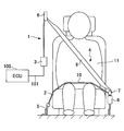
- FIG. 1 is a diagram illustrating an example of a configuration of a seat belt system 1 according to an embodiment.
- the seat belt system 1 is an example of a system mounted on a vehicle.
- the seat belt system 1 includes, for example, a seat belt 4, a retractor 3, a shoulder anchor 6, a tongue 7, a buckle 8, and an ECU (Electronic Control Unit) 100.
- ECU Electronic Control Unit
- the seat belt 4 is an example of a webbing that restrains the occupant 11 sitting on the seat 2 of the vehicle, and is a belt-like member that is wound around the retractor 3 so that it can be pulled out.
- the belt anchor 5 at the tip of the seat belt 4 is fixed to the floor of the vehicle body or the seat 2.
- the retractor 3 is an example of a take-up device that enables the seat belt 4 to be taken up or pulled out. When an acceleration / deceleration or a vehicle angle of a predetermined value or more at the time of a vehicle collision or the like is detected, the seat belt 4 is retracted. To be drawn from.
- the retractor 3 is fixed to the seat 2 or a vehicle body near the seat 2.
- the retractor 3 is an example of a seat belt retractor.
- the retractor 3 winds the seat belt 4 around the spool by the power of the motor.
- the retractor 3 operates a motor based on a signal from a sensor such as a millimeter wave radar to wind the seat belt 4 around a spool before the vehicle collides, and applies a pretension to the seat belt 4 to restrain the passenger by the seat belt 4. Do it quickly.
- the retractor 3 operates the motor when the engagement between the tongue 7 and the buckle 8 is released, and winds up the seat belt 4 with the spool. Further, the retractor 3 operates the motor to adjust the tension of the seat belt 4 in accordance with the driving situation (the state of the vehicle), thereby restraining the occupant by the seat belt 4 and comfort when the seat belt 4 is worn. Improve each.
- the shoulder anchor 6 is an example of a belt insertion tool through which the seat belt 4 is inserted, and is a member that guides the seat belt 4 pulled out from the retractor 3 toward the shoulder of the occupant 11.
- the tongue 7 is an example of a belt insertion tool through which the seat belt 4 is inserted, and is a component that is slidably attached to the seat belt 4 guided by the shoulder anchor 6.
- the buckle 8 is a part to which the tongue 7 is detachably connected, and is fixed to the floor of the vehicle body or the seat 2, for example.
- the portion of the seat belt 4 between the shoulder anchor 6 and the tongue 7 is a shoulder belt portion 9 that restrains the chest and shoulder portions of the occupant 11.
- the portion of the seat belt 4 between the belt anchor 5 and the tongue 7 is a lap belt portion 10 that restrains the waist of the occupant 11.
- the ECU 100 is an example of a control device connected via one or a plurality of wire harnesses 101 so as to be communicable with the retractor 3.
- FIG. 2 is a perspective view showing an example of the configuration of the retractor 3A.
- the retractor 3A is a first example of the retractor 3 shown in FIG.
- the retractor 3 ⁇ / b> A includes, for example, a frame 19, a spool 20 that is rotatably supported by the frame 19 and winds up the seat belt 4, a retainer 16 fixed to the frame 19, and a cover attached to the retainer 16.
- the frame 19 includes a frame plate 18 and a base frame 17.
- the retainer 16 and the frame plate 18 are fixed to the base frame 17.
- the spool 20 is rotatably supported by the base frame 17.
- FIG. 3 is a perspective view showing an example of a configuration of the retractor 3A with a part thereof omitted.
- FIG. 4 is a front view showing an example of a configuration of the retractor 3A with a part thereof omitted.
- FIG. 5 is a side view showing an example of a configuration of the retractor 3A with a part thereof omitted.
- FIG. 6 is an exploded perspective view showing an example of a configuration of the retractor 3A with a part thereof omitted.
- the retractor 3 ⁇ / b> A includes a spool 20, a spiral spring 22, a spring case 23, a first rotating disk 38, a first rotation detecting unit 40, a second rotating disk 58, and a second rotation detecting unit 60. And an arithmetic unit 73 and a motor 24.
- the spool 20 is a rotating member that winds up the seat belt 4.
- the rotating shaft of the spool 20 includes a shaft 20a and a bush 21 fixed to one end of the shaft 20a.
- the spiral spring 22 has one end 22 a connected to the rotating shaft of the spool 20 and the other end connected to the outer peripheral wall of the spring case 23, and elastically urges the spool 20 in the winding direction of the seat belt 4. It is an example of a body.
- One end 22a of the spiral spring 22 is connected to a bush 21 attached to the spool 20 so as to be integrally rotatable, and the spool 20 is constantly urged in the winding direction of the seat belt 4.
- One end 22 a of the spiral spring 22 is hooked in a groove 21 a formed in the bush 21.
- the spring case 23 has an outer peripheral wall to which the other end of the spiral spring 22 is connected, and accommodates the spiral spring 22 inside the outer peripheral wall.
- the spring case 23 is provided so as to be rotatable with respect to the frame plate 18 (see FIG. 2) of the frame 19 around the rotation axis of the spool 20. That is, the spring case 23 is provided so as to be rotatable coaxially with the rotation axis of the spool 20.
- External teeth 23 a are formed on the outer peripheral wall of the spring case 23.
- the first rotary disk 38 is attached to the frame plate 18 so as to be rotatable.
- the first rotating disk 38 includes an annular first magnet holding member 42 and a first magnet 41 that is integrally rotatable with the first magnet holding member 42 and arranged in an annular shape.
- the annular first magnet 41 is formed by alternately arranging N-pole magnets 41 a and S-pole magnets 41 b in the circumferential direction of the first magnet 41.
- the magnetization width of the N-pole magnet 41 a is set to a predetermined first angular width in the circumferential direction of the first magnet 41, and the magnetization width of the S-pole magnet 41 b is the circumference of the first magnet 41.
- a predetermined second angular width is set in the direction.
- the second angular width may be the same as or different from the first angular width.
- the first magnet holding member 42 integrally has a cylindrical first driven gear 43 having external teeth 43 a (see FIG. 5) arranged concentrically with the first magnet holding member 42. . As the first driven gear 43 rotates, the first magnet 41 rotates together with the first driven gear 43 coaxially with the rotation shaft of the first driven gear 43.
- a transmission gear 44 is attached to the shaft 20a of the rotating shaft of the spool 20 so as to be rotatable integrally with the shaft 20a.
- External teeth 44 a are formed on the outer periphery of the transmission gear 44.
- the external teeth 43 a of the first driven gear 43 mesh with the external teeth 44 a of the transmission gear 44.
- the first rotation detection unit 40 is an example of a rotation detection unit that detects the rotation of the spool 20.
- the first rotation detection unit 40 detects the rotation of the spool 20 by detecting the rotation of the first magnet 41.
- the first rotation detection unit 40 includes, for example, a first magnetic detection unit 40a and a second magnetic detection unit 40b.
- the first magnetic detection unit 40 a and the second magnetic detection unit 40 b detect the strength of the magnetic field (magnetic field) that changes as the first magnet 41 rotates.
- a specific example of the first magnetic detection unit 40a and the second magnetic detection unit 40b is a Hall element.
- the Hall element is an example of a semiconductor element that detects a magnetic change by the Hall effect.
- the transmission gear 44 that rotates integrally with the rotation shaft of the spool 20 rotates.
- the first driven gear 43 formed with the outer teeth 43a meshing with the outer teeth 44a of the transmission gear 44 rotates, so that the first magnet 41 of the first rotating disk 38 is rotated. Rotate. That is, when the spool 20 rotates in the seat belt 4 pull-out direction, the first magnet 41 rotates in a rotation direction corresponding to the seat belt 4 pull-out direction in conjunction with the rotation of the spool 20.
- the first magnetic detection unit 40a and the second magnetic detection unit 40b respectively detect the N-pole magnet 41a and the S-pole magnet 41b.
- a detection signal whose phase is inverted is output.
- the amplitude of the detection signal is proportional to the strength of the detected magnetic field, for example.
- the phase of the detection signal output from the first magnetic detection unit 40a is the second magnetic detection unit.
- the phase of the detection signal output from the unit 40b is shifted by a predetermined amount.
- the calculation unit 73 detects the rotation amount (rotation position) of the spool 20 by counting the number of phase inversions of the detection signal output from each of the first magnetic detection unit 40a and the second magnetic detection unit 40b. To do. In addition, the calculation unit 73 rotates the spool 20 based on the phase shift between the detection signal output from the first magnetic detection unit 40a and the detection signal output from the second magnetic detection unit 40b. It is determined whether the direction is the pulling direction of the seat belt 4 or the winding direction of the seat belt 4.
- the second rotating disk 58 is rotatably attached to the frame plate 18.
- the second rotating disk 58 includes an annular second magnet holding member 62 and a second magnet 61 arranged in an annular shape so as to be rotatable integrally with the second magnet holding member 62. Yes.
- the annular second magnet 61 is formed by alternately arranging N-pole magnets 61 a and S-pole magnets 61 b in the circumferential direction of the second magnet 61.
- the magnetization width of the N-pole magnet 61 a is set to a predetermined third angular width in the circumferential direction of the second magnet 61, and the magnetization width of the S-pole magnet 61 b is the circumference of the second magnet 61.
- a predetermined fourth angular width is set in the direction.
- the fourth angular width may be the same as or different from the third angular width.
- the second magnet holding member 62 integrally includes a cylindrical second driven gear 63 having external teeth 63 a disposed concentrically with the second magnet holding member 62. As the second driven gear 63 rotates, the second magnet 61 rotates coaxially with the rotation axis of the second driven gear 63 together with the second driven gear 63.
- the external teeth 63a of the second driven gear 63 mesh with the external teeth 23a of the spring case 23.
- the second rotation detector 60 is an example of a rotation detector that detects the rotation of the spring case 23.
- the second rotation detection unit 60 detects the rotation of the spring case 23 by detecting the rotation of the second magnet 61.
- the second rotation detection unit 60 includes, for example, a third magnetic detection unit 60a and a fourth magnetic detection unit 60b.
- the third magnetic detection unit 60 a and the fourth magnetic detection unit 60 b detect the strength of the magnetic field (magnetic field) that changes as the second magnet 61 rotates.
- Specific examples of the third magnetic detection unit 60a and the fourth magnetic detection unit 60b include Hall elements.
- the Hall element is an example of a semiconductor element that detects a magnetic change by the Hall effect.
- the third magnetic detection unit 60a and the fourth magnetic detection unit 60b respectively detect the N-pole magnet 61a and the S-pole magnet 61b.
- a detection signal whose phase is inverted is output.
- the amplitude of the detection signal is proportional to the strength of the detected magnetic field, for example.
- the phase of the detection signal output from the third magnetic detector 60a is the fourth magnetic detection.
- the phase of the detection signal output from the unit 60b is shifted by a predetermined amount.
- the calculation unit 73 counts the number of inversions of the phase of the detection signal output from each of the third magnetic detection unit 60a and the fourth magnetic detection unit 60b, thereby calculating the rotation amount (rotation position) of the spring case 23. Detect. In addition, the calculation unit 73 determines whether the spring case 23 has a phase shift between the detection signal output from the third magnetic detection unit 60a and the detection signal output from the fourth magnetic detection unit 60b. It is determined whether the rotation direction is the pulling direction of the seat belt 4 or the winding direction of the seat belt 4.
- the calculation unit 73 calculates a difference between the rotation amount of the spool 20 whose rotation is detected by the first rotation detection unit 40 and the rotation amount of the spring case 23 whose rotation is detected by the second rotation detection unit 60 (hereinafter, referred to as “rotation amount”). (Referred to as difference D), and the calculation result of difference D is output.
- rotation amount a difference between the rotation amount of the spool 20 whose rotation is detected by the first rotation detection unit 40 and the rotation amount of the spring case 23 whose rotation is detected by the second rotation detection unit 60 (hereinafter, referred to as “rotation amount”).
- difference D the calculation result of difference D is output.
- Specific examples of the calculation unit 73 include a microcomputer, an ASIC (Application Specific Integrated Circuit), and an FPGA (Field Programmable Gate Array).
- ECU100 acquires the calculation result of the difference D obtained by the calculating part 73 via the wire harness 101.
- FIG. The ECU 100 controls the driving of the motor 24 according to the obtained calculation result of the difference D.
- the ECU 100 includes a processor such as a CPU (Central Processing ⁇ ⁇ Unit) and a memory.
- Each function of ECU 100 (such as a function for controlling driving of motor 24) is realized by a program processed by the processor. Programs for realizing these functions are stored in the memory.
- the ECU 100 controls the driving of the motor 24 in this way, so that the motor 24 rotates the spring case 23 according to the difference D.
- the tension of the seat belt 4 changes (for example, increases). Therefore, when the motor 24 rotates the spring case 23 according to the difference D, the motor 24 can adjust the tension of the seat belt 4 continuously and continuously with high accuracy.
- ECU100 controls the drive of the motor 24, for example so that the difference D may correspond to a predetermined target value.
- the motor 24 rotates the spring case 23 so that the difference D matches a predetermined target value.
- the motor 24 can adjust the tension of the seat belt 4 to a predetermined target tension value with high accuracy.
- the ECU 100 may control the driving of the motor 24 so that a change amount (hereinafter referred to as a change amount A) that changes according to the difference D matches a predetermined target value.
- a change amount A a change amount that changes according to the difference D matches a predetermined target value.
- the motor 24 rotates the spring case 23 so that the change amount A matches a predetermined target value. Accordingly, the motor 24 can adjust the tension of the seat belt 4 to a predetermined target tension value with high accuracy.
- change amount A include the tension of the seat belt 4 and the winding force of the seat belt 4 by the spiral spring 22.
- the ECU100 controls the drive of the motor 24, for example so that the difference D or the variation
- the ECU 100 drives the motor 24 to move the spring case 23 in the direction in which the seat belt 4 is pulled out.
- the same amount of rotation can be rotated. Therefore, even when the seat belt 4 is pulled out, the tension of the spiral spring 22 in the winding direction of the seat belt 4 can be suppressed and the tension of the seat belt 4 can be kept constant at all times.
- the ECU 100 drives the motor case 24 to move the spring case 23 in the direction in which the seat belt 4 is pulled out from the amount of rotation.
- a large amount of rotation can be rotated.
- the ECU 100 increases or decreases the tension of the seat belt 4 by keeping the urging force of the spiral spring 22 from rising in the seat belt 4 winding direction in accordance with the amount of the seat belt 4 pulled out. it can. As a result, the wearing operation of the seat belt 4 becomes light.
- the amount of the seat belt withdrawn increases, the amount of winding of the spring spring also increases uniformly, so that the tension of the seat belt 4 becomes higher. As a result, the wearing operation of the seat belt 4 becomes heavy.
- the ECU 100 can freely adjust the tension of the seat belt 4 according to the difference D while the seat belt 4 is worn after the tongue 7 and the buckle 8 are connected. Therefore, the ECU 100 can reduce the feeling of pressure applied to the occupant 11 when the seat belt 4 is worn by reducing the tension of the seat belt 4 according to the difference D.
- ECU100 may control the drive of the motor 24, for example so that the difference D or the variation
- the motor 24 rotates the spring case 23 so that the difference D or the change amount A matches the target value set according to the state of the vehicle.
- the motor 24 can adjust the tension of the seat belt 4 to a target tension value suitable for each state of the vehicle with high accuracy.
- the state of the vehicle includes, for example, whether or not the seat belt 4 is pulled out, whether or not the occupant 11 is present, traveling speed of the vehicle, acceleration of the vehicle, steering operation, accelerator operation, brake operation, operation of the buckle 8, door operation, and operation by the occupant This refers to a state that represents a possible operation input of an on-vehicle selection switch.
- the ECU 100 controls the driving of the motor 24 so that the difference D or the change amount A matches the target value set according to the traveling speed and / or acceleration of the vehicle.
- the ECU 100 can increase the tension of the seat belt 4 as the traveling speed and / or acceleration of the vehicle increases. Therefore, the posture retention of the occupant 11 is improved.
- the ECU 100 may control the driving of the motor 24 so that the difference D or the change amount A matches the target value set according to the operation of the occupant.
- the passenger can set the tension of the seat belt 4 to a desired tension by manual operation using a dial, a switch, or the like or by voice operation.
- the ECU 100 increases the tension of the seat belt 4 according to the difference D until the seat belt 4 is stored in the retractor 3 when the connection between the tongue 7 and the buckle 8 is released. Can be improved.
- the spring case 23 in which the external teeth 23a are formed functions as a worm wheel.
- the motor 24 rotates the spring case 23 via a worm 25 that meshes with the external teeth 23a.
- the external teeth 23 a rotate the worm 25 for rotating the spring case 23 and the second magnet 61 for rotating the second magnet 61 so that the second rotation detector 60 detects the rotation of the spring case 23. It meshes with both the transmission gear 63.
- the gear for detecting the rotation of the spring case 23 and the gear for driving the rotation of the spring case 23 are shared as the external teeth 23a. By sharing the gear, it is possible to reduce the size and cost.
- the worm 25 may have a lead angle capable of self-locking. Thereby, transmission of rotation from the spring case 23 to the worm 25 can be suppressed. Therefore, the ECU 100 can maintain the urging force of the spiral spring 22 in the winding direction of the seat belt 4 even when the motor 24 is not energized. As a result, it is possible to reduce the power consumed by the motor 24 during the period when the tension of the seat belt 4 is not required to be adjusted.
- the retractor 3 ⁇ / b> A has a substrate 70.
- the substrate 70 includes a first rotation detection unit 40, a second rotation detection unit 60, and a calculation unit 73. Since the first rotation detection unit 40, the second rotation detection unit 60, and the calculation unit 73 are arranged on a common board 70, the number of components can be reduced.
- the ECU 100 acquires the detection signals output from the first rotation detection unit 40 and the second rotation detection unit 60 via the wire harness 101 and the ECU 100 calculates the difference D is conceivable.
- the wire harness 101 for transmitting the detection signal output from the first rotation detection unit 40 to the ECU 100 and the detection signal output from the second rotation detection unit 60 are transmitted to the ECU 100.
- the wire harness 101 is required separately.
- the calculation unit 73 outputs a signal corresponding to the calculation result of the difference D to the ECU 100 via the wire harness 101. Therefore, the number of wire harnesses 101 can be reduced as compared with the above-described embodiment in which separate wire harnesses 101 are necessary for transmitting the detection signals.
- the substrate 70 is disposed between the spool 20 and the spring case 23.
- the substrate 70 has a first substrate surface on the spool 20 side and a second substrate surface on the spring case 23 side (the opposite side to the first substrate surface). Since the first rotation detection unit 40 is disposed on the surface of the first substrate and the second rotation detection unit 60 is disposed on the surface of the second substrate, the two rotation bodies of the spool 20 and the spring case 23 are arranged. The rotation detection can be realized on one common substrate 70.
- the first rotation detector 40 On the surface of the first substrate, the first rotation detector 40 is arranged so as to face the first magnet 41 of the first rotating disk 38. On the surface of the second substrate, the second rotation detector 60 is disposed so as to face the second magnet 61 of the second rotating disk 58. Since the magnet and the rotation detection unit are arranged to face each other, the rotation detection accuracy is improved.
- FIG. 7 is a diagram showing an example of the configuration of the retractor 3B.
- the retractor 3B is a second example of the retractor 3 shown in FIG. Of the configuration and effect of the retractor 3B, the description of the same configuration and effect as the retractor 3A is omitted by using the above description.
- the first rotation detection unit 40 and the second rotation detection unit 60 are mounted on a common substrate 70.
- the first rotation detection unit 40 and the second rotation detection unit 60 are mounted on separate substrates.
- the first rotation detection unit 40 is mounted on the substrate 71.
- the second rotation detection unit 60 is mounted on the substrate 72.
- the computing unit 73 is mounted on the substrate 71 or the substrate 72.
- the calculation unit 73 may be mounted on a board different from the boards 71 and 72.
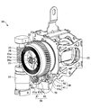
- FIG. 8 is a front view showing an example of the configuration of the retractor 3C.
- FIG. 9 is a side view showing an example of the configuration of the retractor 3C.
- the description of the same configuration and effect as the retractor 3A is omitted or simplified by using the above description.
- the retractor 3 ⁇ / b> C includes a spool 20 that winds up the seat belt, a substrate case 180 that accommodates the substrate 170, a retainer 116 that is fixed to the base frame 17 together with the substrate case 180, and a cover 115 that is attached to the retainer 116.
- the retainer 116 covers part or all of the substrate 170 between the substrate case 180 and the retainer 116.
- a substrate 170 and a substrate case 180 are sandwiched between the retainer 116 and the base frame 17.
- the worm 25 is rotated by the motor 24.
- a worm cover 26 that houses the worm 25 is fixed to the retainer 116.
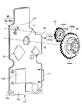
- FIG. 10 is an exploded perspective view showing an example of the configuration of the retractor 3C with a part thereof omitted.
- illustration of the spiral spring 22 housed in the spring case 23 and the cover 115 covering the spiral spring 22 is omitted to improve the visibility of the drawing.
- the retractor 3C includes a substrate 170.
- the substrate 170 is disposed between the spool 20 and the spring case 23, and is disposed between the substrate case 180 and the retainer 116.
- the substrate 170 has a first substrate surface 171 on the spool 20 side and a second substrate surface 172 on the spring case 23 side (opposite side to the first substrate surface).
- the first rotation detector 40 is disposed on the first substrate surface 171
- the second rotation detector 60 is disposed on the second substrate surface 172. Therefore, the rotation detection of the two rotating bodies of the spool 20 and the spring case 23 can be realized on one common substrate 170.
- the retractor 3 ⁇ / b> C includes a first magnet 141 and a second magnet 161.
- the first magnet 141 rotates with the rotation of the spool 20 at an axis different from that of the spool 20.
- the second magnet 161 rotates on the same axis as the spool 20 as the spring case 23 rotates.
- FIG. 11 is a perspective view showing an example of the positional relationship between the first rotation detector and the first magnet.
- the transmission gear 144 rotates on the same axis 151 as the spool 20 as the spool 20 rotates.
- the axis 151 represents the rotation axis center of the shaft 20 a of the spool 20.
- the shaft 20 a is fitted in a central hole 144 b formed in the transmission gear 144.
- the transmission gear 144 that rotates integrally with the shaft 20a and concentrically rotates.
- the driven gear 143 formed with the outer teeth 143a meshing with the outer teeth 144a of the transmission gear 144 rotates.
- the driven gear 143 has an annular first magnet 141 fitted inside the external teeth 143a. Therefore, when the driven gear 143 rotates, the first magnet 141 also rotates.
- the shaft center 152 represents the center of the protruding shaft 184 (see FIG. 10), which is the rotation shaft of the driven gear 143.
- the protruding shaft 184 protrudes from the surface of the substrate case 180 on the spool 20 side.
- the protruding shaft 184 is fitted into a central hole 143 b formed in the driven gear 143.
- the first magnet 141 is formed by alternately arranging N-pole magnets 141 a and S-pole magnets 141 b in the circumferential direction of the first magnet 141.
- the magnetization width of the N-pole magnet 141 a is set to a predetermined first angular width in the circumferential direction of the first magnet 141
- the magnetization width of the S-pole magnet 141 b is the circumference of the first magnet 41.
- a predetermined second angular width is set in the direction. The second angular width may be the same as or different from the first angular width.
- FIG. 12 is a perspective view showing an example of the positional relationship between the second rotation detector and the second magnet.
- the second magnet 161 has the same axis 151 as the spool 20 and rotates as the spring case 23 rotates.
- the axis 151 represents the rotation axis center of the shaft 20 a of the spool 20.
- the second magnet 161 is attached to the bottom surface 23b of the spring case 23 on the substrate 70 side.
- the shaft 20 a passes through the substrate hole 173 formed in the substrate 170 and the annular second magnet 161 and is fitted into the spring case 23. Therefore, the second magnet 161 rotates with the rotation of the spring case 23 at the same axis 151 as the spool 20.
- the second magnet 161 is formed by alternately arranging N-pole magnets 161 a and S-pole magnets 161 b in the circumferential direction of the second magnet 161.
- the magnetization width of the N-pole magnet 161 a is set to a predetermined third angular width in the circumferential direction of the second magnet 161
- the magnetization width of the S-pole magnet 161 b is the circumference of the second magnet 161.
- a predetermined fourth angular width is set in the direction.
- the fourth angular width may be the same as or different from the third angular width.
- the first rotation detection unit 40 can detect the rotation of the spool 20 by detecting the strength of the magnetic field that changes due to the rotation of the first magnet 141.
- the second rotation detection unit 60 can detect the rotation of the spring case 23 by detecting the strength of the magnetic field that changes as the second magnet 161 rotates.
- the first magnet 141 rotates with an axis 152 different from that of the spool 20, and the second magnet 161 rotates with the same axis 151 as the spool 20.
- the magnetic field by the 1st magnet 141 interferes with the magnetic detection parts 60a and 60b of the 2nd rotation detection part 60, and the magnetic field by the 2nd magnet 161 is the 1st rotation detection part 40. Interference with the magnetic detectors 40a and 40b is suppressed. As a result, it is possible to prevent a decrease in accuracy of rotation detection.
- the shaft 20 a passes through a case hole 181 formed in the substrate case 180, a substrate hole 173 formed in the substrate 170, and a retainer hole 116 a formed in the retainer 116.
- the boss 182 protruding from the surface of the substrate case 180 on the substrate 170 side is inserted into a positioning hole 175 formed in the substrate 170.
- the boss 182 is concentric with the protruding shaft 184. Therefore, when the boss 182 is inserted into the positioning hole 175, the first rotation detection unit 40 disposed on the first substrate surface 171 of the substrate 170 and the first magnet 141 that rotates around the protruding shaft 184. Can be reduced.
- the first rotation detection unit 40 detects the rotation of the first magnet 141 through a detection window 183 formed on the bottom surface of the substrate case 180.
- the detection window 183 is preferably not a penetrating window in order to prevent water from entering.
- the control unit 110 may be disposed on the substrate 170 (for example, the first substrate surface 171).
- the control unit 110 responds to a difference D between the rotation amount of the spool 20 whose rotation is detected by the first rotation detection unit 40 and the rotation amount of the spring case 23 whose rotation is detected by the second rotation detection unit 60.
- the drive of the motor 24 is controlled. That is, the control unit 110 is hardware having the same function as the ECU 100 (see FIG. 1).
- the retractor 3C with the hardware configuration that realizes the above-described functions of the ECU 100, it is not necessary to prepare the ECU 100 that is separate from the retractor 3C, so that the mounting property to the vehicle is improved.
- the control unit 110 includes, for example, a processor such as a CPU (Central Processing Unit) and a memory. Each function (such as a function for controlling driving of the motor 24) of the control unit 110 is realized by a program processed by the processor. Programs for realizing these functions are stored in the memory.
- the control unit 110 may be configured by an ASIC or FPGA.
- Information indicating the state of the vehicle (for example, information indicating a connection state between the buckle and the tongue) is input to the control unit 110 via a connector 174 attached to the board 170, for example.
- a power supply voltage necessary for the operation of components on the substrate 170 such as the control unit 110 is input via the connector 174.
- the calculation unit 73 for calculating the difference D is disposed on the substrate 170 (for example, the first substrate surface 171).
- the calculation unit 73 outputs the calculation result of the difference D to the control unit 110.
- the calculation unit 73 may be built in the control unit 110.
Landscapes
- Engineering & Computer Science (AREA)
- Automation & Control Theory (AREA)
- Mechanical Engineering (AREA)
- Automotive Seat Belt Assembly (AREA)
Abstract
シートベルトを巻き取るスプールと、前記スプールの回転軸に一端が接続され、前記スプールを前記シートベルトの巻き取り方向に付勢するスパイラルスプリングと、前記スパイラルスプリングの他端が連結され、前記回転軸を中心に回転可能に設けられたスプリングケースと、前記スプールの回転を検知する第1の回転検知部と、前記スプリングケースの回転を検知する第2の回転検知部と、前記第1の回転検知部により回転が検知された前記スプールの回転量と前記第2の回転検知部により回転が検知された前記スプリングケースの回転量との差に応じて、前記スプリングケースを回転させるモータとを備える、シートベルトリトラクタ。
Description
本発明は、シートベルトリトラクタ及びシートベルトシステムに関する。
従来、ウェビングの巻取軸と、前記巻取軸に一端が接続されたゼンマイバネと、前記ゼンマイバネの他端が係止されると共に回転可能に設けられたスプリング保持箱とを備えた、ウェビング巻取装置が知られている(例えば、特許文献1を参照)。このウェビング巻取装置は、巻取軸の回転方向検出とスプリング保持箱の回転位置検出とにより、スプリング保持箱をモータで回転させてゼンマイバネのセット位置を変更することで、ゼンマイバネによる巻き取り付勢力を加減する。
しかしながら、ゼンマイバネによるシートベルトの張力は、巻取軸がスプリング保持箱に対してどれだけ回転したかに応じて変わる。そのため、スプリング保持箱をモータで回転させるときに巻取軸とスプリング保持箱のそれぞれの回転量が分からないと、シートベルトの張力を高精度に調整することは難しい。
そこで、本開示の一態様は、シートベルトの張力を高精度に調整できる、シートベルトリトラクタ及びシートベルトシステムの提供を目的とする。
上記目的を達成するため、本開示の第1の態様では、
シートベルトを巻き取るスプールと、
前記スプールの回転軸に一端が接続され、前記スプールを前記シートベルトの巻き取り方向に付勢するスパイラルスプリングと、
前記スパイラルスプリングの他端が連結され、前記回転軸を中心に回転可能に設けられたスプリングケースと、
前記スプールの回転を検知する第1の回転検知部と、
前記スプリングケースの回転を検知する第2の回転検知部と、
前記第1の回転検知部により回転が検知された前記スプールの回転量と前記第2の回転検知部により回転が検知された前記スプリングケースの回転量との差に応じて、前記スプリングケースを回転させるモータとを備える、シートベルトリトラクタが提供される。
シートベルトを巻き取るスプールと、
前記スプールの回転軸に一端が接続され、前記スプールを前記シートベルトの巻き取り方向に付勢するスパイラルスプリングと、
前記スパイラルスプリングの他端が連結され、前記回転軸を中心に回転可能に設けられたスプリングケースと、
前記スプールの回転を検知する第1の回転検知部と、
前記スプリングケースの回転を検知する第2の回転検知部と、
前記第1の回転検知部により回転が検知された前記スプールの回転量と前記第2の回転検知部により回転が検知された前記スプリングケースの回転量との差に応じて、前記スプリングケースを回転させるモータとを備える、シートベルトリトラクタが提供される。
また、上記目的を達成するため、本開示の第2の態様では、
当該シートベルトリトラクタと、前記差に応じて前記モータの駆動を制御する制御装置とを備える、シートベルトシステムが提供される。
当該シートベルトリトラクタと、前記差に応じて前記モータの駆動を制御する制御装置とを備える、シートベルトシステムが提供される。
本開示の態様によれば、シートベルトの張力を高精度に調整することができる。
以下、本開示に係る実施形態を図面を参照して説明する。
図1は、一実施形態に係るシートベルトシステム1の構成の一例を示す図である。シートベルトシステム1は、車両に搭載されたシステムの一例である。シートベルトシステム1は、例えば、シートベルト4と、リトラクタ3と、ショルダーアンカー6と、タング7と、バックル8と、ECU(Electronic Control Unit)100とを備える。
シートベルト4は、車両のシート2に座る乗員11を拘束するウェビングの一例であり、リトラクタ3に引き出し可能に巻き取られる帯状部材である。シートベルト4の先端のベルトアンカー5は、車体の床又はシート2に固定される。
リトラクタ3は、シートベルト4の巻き取り又は引き出しを可能にする巻き取り装置の一例であり、車両衝突時等の所定値以上の加減速度または車両角度が検知されると、シートベルト4がリトラクタ3から引き出されることを制限する。リトラクタ3は、シート2又はシート2の近傍の車体に固定される。リトラクタ3は、シートベルトリトラクタの一例である。
リトラクタ3は、モータの動力によりシートベルト4をスプールに巻き取る。リトラクタ3は、車両衝突前に、ミリ波レーダー等のセンサからの信号に基づいてモータを作動してシートベルト4をスプールに巻き取り、シートベルト4にプリテンションを与えてシートベルト4による乗員拘束を迅速に行う。また、リトラクタ3は、タング7とバックル8との係合が解除された時にモータを作動してシートベルト4をスプールで巻き取る。更に、リトラクタ3は、モータを作動してシートベルト4の張力をドライビングシチュエーション(車両の状態)に応じて調整することで、シートベルト4による乗員の拘束性やシートベルト4の装着時の快適性をそれぞれ向上させる。
ショルダーアンカー6は、シートベルト4が挿通するベルト挿通具の一例であり、リトラクタ3から引き出されたシートベルト4を乗員11の肩部の方へガイドする部材である。
タング7は、シートベルト4が挿通するベルト挿通具の一例であり、ショルダーアンカー6によりガイドされたシートベルト4にスライド可能に取り付けられた部品である。
バックル8は、タング7が着脱可能に連結される部品であり、例えば、車体の床又はシート2に固定される。
タング7がバックル8に係合された状態で、ショルダーアンカー6とタング7との間のシートベルト4の部分が、乗員11の胸部及び肩部を拘束するショルダーベルト部9である。タング7がバックル8に係合された状態で、ベルトアンカー5とタング7との間のシートベルト4の部分が、乗員11の腰部を拘束するラップベルト部10である。
ECU100は、リトラクタ3と通信可能に一又は複数本のワイヤハーネス101を介して接続された制御装置の一例である。
図2は、リトラクタ3Aの構成の一例を示す斜視図である。リトラクタ3Aは、図1に示されたリトラクタ3の第一の例である。
図2において、リトラクタ3Aは、例えば、フレーム19と、フレーム19に回転可能に支持されてシートベルト4を巻き取るスプール20と、フレーム19に固定されたリテーナ16と、リテーナ16に取り付けられたカバー15とを備える。フレーム19は、フレームプレート18と、ベースフレーム17とを有する。リテーナ16及びフレームプレート18は、ベースフレーム17に固定されている。スプール20は、ベースフレーム17に回転可能に支持されている。
図3~図6では、各図面の視認性向上のため、カバー15、リテーナ16及びフレームプレート18の図示が省略されている。図3は、リトラクタ3Aの構成の一例を一部省略して示す斜視図である。図4は、リトラクタ3Aの構成の一例を一部省略して示す正面図である。図5は、リトラクタ3Aの構成の一例を一部省略して示す側面図である。図6は、リトラクタ3Aの構成の一例を一部省略して示す分解斜視図である。以下、図3~図6を参照して、リトラクタ3Aの構成の一例について詳細に説明する。
リトラクタ3Aは、スプール20と、スパイラルスプリング22と、スプリングケース23と、第1の回転ディスク38と、第1の回転検知部40と、第2の回転ディスク58と、第2の回転検知部60と、演算部73と、モータ24とを備える。
スプール20は、シートベルト4を巻き取る回転部材である。スプール20の回転軸は、シャフト20aと、シャフト20aの一端に固定されたブッシュ21とを含んで構成される。
スパイラルスプリング22は、スプール20の回転軸に接続された一端22aと、スプリングケース23の外周壁に連結された他端とを有し、スプール20をシートベルト4の巻き取り方向に付勢する弾性体の一例である。スパイラルスプリング22は、スプール20に一体回転可能に取り付けられたブッシュ21に一端22aが連結されて、スプール20をシートベルト4の巻き取り方向に常時付勢する。スパイラルスプリング22の一端22aは、ブッシュ21に形成された溝21aに引っ掛けられている。
スプリングケース23は、スパイラルスプリング22の他端が連結された外周壁を有し、スパイラルスプリング22を当該外周壁の内側に収容する。スプリングケース23は、スプール20の回転軸を中心にフレーム19のフレームプレート18(図2参照)に対して回転可能に設けられている。つまり、スプリングケース23は、スプール20の回転軸と同軸に回転可能に設けられている。スプリングケース23の外周壁には、外歯23aが形成されている。
第1の回転ディスク38は、フレームプレート18に対して回転可能に取り付けられている。第1の回転ディスク38は、円環状の第1のマグネット保持部材42と、第1のマグネット保持部材42に一体回転可能にかつ円環状に配設された第1のマグネット41とを有している。円環状の第1のマグネット41は、N極マグネット41aとS極マグネット41bとが第1のマグネット41の円周方向に交互に配設されて形成されている。N極マグネット41aの着磁幅が第1のマグネット41の円周方向に所定の第1の角度幅に設定されているとともに、S極マグネット41bの着磁幅が第1のマグネット41の円周方向に所定の第2の角度幅に設定されている。第2の角度幅は、第1の角度幅と同じでも違ってもよい。第1のマグネット保持部材42は、第1のマグネット保持部材42と同心に配設された外歯43a(図5参照)を有する筒状の第1の被伝動ギア43を一体に有している。第1のマグネット41は、第1の被伝動ギア43の回転に伴って、第1の被伝動ギア43と一体に第1の被伝動ギア43の回転軸と同軸に回転する。
スプール20の回転軸のシャフト20aには、伝動ギア44がシャフト20aと一体回転可能にかつ同心に取り付けられている。伝動ギア44の外周部には外歯44aが形成されている。第1の被伝動ギア43の外歯43aは、伝動ギア44の外歯44aと噛み合っている。
第1の回転検知部40は、スプール20の回転を検知する回転検知部の一例である。第1の回転検知部40は、例えば、第1のマグネット41の回転を検知することによってスプール20の回転を検知する。第1の回転検知部40は、例えば、第1の磁気検知部40aと第2の磁気検知部40bと有する。第1の磁気検知部40aと第2の磁気検知部40bは、それぞれ、第1のマグネット41の回転に伴って変化する磁気(磁界)の強さを検知する。第1の磁気検知部40a及び第2の磁気検知部40bの具体例として、ホール素子が挙げられる。ホール素子は、ホール効果によって磁気変化を検出する半導体素子の一例である。
スプール20がシートベルト4の引き出し方向に回転すると、スプール20の回転軸と一体に回転する伝動ギア44が回転する。伝動ギア44が回転すると、伝動ギア44の外歯44aと噛み合っている外歯43aが形成された第1の被伝動ギア43が回転するので、第1の回転ディスク38の第1のマグネット41が回転する。つまり、スプール20がシートベルト4の引き出し方向に回転すると、スプール20の回転に連動して、シートベルト4の引き出し方向に対応する回転方向に第1のマグネット41が回転する。
第1のマグネット41が回転すると、第1の磁気検知部40aと第2の磁気検知部40bは、それぞれ、N極マグネット41aを検知しているときとS極マグネット41bを検知しているときとで位相が反転する検知信号を出力する。検知信号の振幅は、例えば、検出された磁界の強さに比例する。また、第1の磁気検知部40aの配置位置は、第2の磁気検知部40bの配置位置と異なるので、第1の磁気検知部40aから出力される検知信号の位相は、第2の磁気検知部40bから出力される検知信号の位相に対して所定量ずれている。
演算部73は、第1の磁気検知部40aと第2の磁気検知部40bのそれぞれから出力された検知信号の位相の反転回数をカウントすることで、スプール20の回転量(回転位置)を検知する。また、演算部73は、第1の磁気検知部40aから出力された検知信号と第2の磁気検知部40bから出力された検知信号との間の位相のずれ方に基づいて、スプール20の回転方向がシートベルト4の引き出し方向であるか、シートベルト4の巻き取り方向であるかを判断する。
第2の回転ディスク58は、フレームプレート18に対して回転可能に取り付けられている。第2の回転ディスク58は、円環状の第2のマグネット保持部材62と、第2のマグネット保持部材62に一体回転可能にかつ円環状に配設された第2のマグネット61とを有している。円環状の第2のマグネット61は、N極マグネット61aとS極マグネット61bとが第2のマグネット61の円周方向に交互に配設されて形成されている。N極マグネット61aの着磁幅が第2のマグネット61の円周方向に所定の第3の角度幅に設定されているとともに、S極マグネット61bの着磁幅が第2のマグネット61の円周方向に所定の第4の角度幅に設定されている。第4の角度幅は、第3の角度幅と同じでも違ってもよい。第2のマグネット保持部材62は、第2のマグネット保持部材62と同心に配設された外歯63aを有する筒状の第2の被伝動ギア63を一体に有している。第2のマグネット61は、第2の被伝動ギア63の回転に伴って、第2の被伝動ギア63と一体に第2の被伝動ギア63の回転軸と同軸に回転する。
第2の被伝動ギア63の外歯63aは、スプリングケース23の外歯23aと噛み合っている。
第2の回転検知部60は、スプリングケース23の回転を検知する回転検知部の一例である。第2の回転検知部60は、例えば、第2のマグネット61の回転を検知することによってスプリングケース23の回転を検知する。第2の回転検知部60は、例えば、第3の磁気検知部60aと第4の磁気検知部60bと有する。第3の磁気検知部60aと第4の磁気検知部60bは、それぞれ、第2のマグネット61の回転に伴って変化する磁気(磁界)の強さを検知する。第3の磁気検知部60a及び第4の磁気検知部60bの具体例として、ホール素子が挙げられる。ホール素子は、ホール効果によって磁気変化を検出する半導体素子の一例である。
スプリングケース23がモータ24の駆動によりシートベルト4の引き出し方向に回転すると、スプリングケース23の外歯23aと噛み合っている外歯63aが形成された第2の被伝動ギア63が回転する。第2の被伝動ギア63の回転により、第2の回転ディスク58の第2のマグネット61が回転する。つまり、スプリングケース23がシートベルト4の引き出し方向に回転すると、スプリングケース23の回転に連動して、シートベルト4の引き出し方向に対応する回転方向に第2のマグネット61が回転する。
第2のマグネット61が回転すると、第3の磁気検知部60aと第4の磁気検知部60bは、それぞれ、N極マグネット61aを検知しているときとS極マグネット61bを検知しているときとで位相が反転する検知信号を出力する。検知信号の振幅は、例えば、検出された磁界の強さに比例する。また、第3の磁気検知部60aの配置位置は、第4の磁気検知部60bの配置位置と異なるので、第3の磁気検知部60aから出力される検知信号の位相は、第4の磁気検知部60bから出力される検知信号の位相に対して所定量ずれている。
演算部73は、第3の磁気検知部60aと第4の磁気検知部60bのそれぞれから出力された検知信号の位相の反転回数をカウントすることで、スプリングケース23の回転量(回転位置)を検知する。また、演算部73は、第3の磁気検知部60aから出力された検知信号と第4の磁気検知部60bから出力された検知信号との間の位相のずれ方に基づいて、スプリングケース23の回転方向がシートベルト4の引き出し方向であるか、シートベルト4の巻き取り方向であるかを判断する。
演算部73は、第1の回転検知部40により回転が検知されたスプール20の回転量と、第2の回転検知部60により回転が検知されたスプリングケース23の回転量との差(以下、差Dと称する)を演算し、差Dの演算結果を出力する。演算部73の具体例として、マイクロコンピュータ、ASIC(Application Specific Integrated Circuit)、FPGA(Field Programmable Gate Array)などが挙げられる。
ECU100(図1参照)は、演算部73によって得られた差Dの演算結果をワイヤハーネス101を介して取得する。ECU100は、取得した差Dの演算結果に応じて、モータ24の駆動を制御する。ECU100は、CPU(Central Processing Unit)などのプロセッサと、メモリとを有する。ECU100が有する各機能(モータ24の駆動を制御する機能など)は、プロセッサが処理するプログラムによって実現される。それらの各機能を実現するためのプログラムは、当該メモリに格納されている。
ECU100がこのようにモータ24の駆動を制御することにより、モータ24は、差Dに応じてスプリングケース23を回転させる。例えば、差Dが大きくなるほど、シートベルト4の張力は変化(例えば、増加)する。よって、モータ24が差Dに応じてスプリングケース23を回転させることで、モータ24はシートベルト4の張力を連続的且つ無段階に高精度に調整できる。
ECU100は、例えば、差Dが所定の目標値に一致するように、モータ24の駆動を制御する。ECU100がこのようにモータ24の駆動を制御することにより、モータ24は、差Dが所定の目標値に一致するように、スプリングケース23を回転させる。これにより、モータ24はシートベルト4の張力を所定の目標張力値に高精度に調整できる。
あるいは、ECU100は、差Dに応じて変化する変化量(以下、変化量Aと称する)が所定の目標値に一致するように、モータ24の駆動を制御してもよい。ECU100がこのようにモータ24の駆動を制御することにより、モータ24は、変化量Aが所定の目標値に一致するように、スプリングケース23を回転させる。これにより、モータ24は、シートベルト4の張力を所定の目標張力値に高精度に調整できる。
変化量Aの具体例として、シートベルト4の張力、スパイラルスプリング22によるシートベルト4の巻き取り力などが挙げられる。
ECU100は、例えば、差D又は変化量Aが所定の一定の目標値に維持されるように、モータ24の駆動を制御する。これにより、ECU100は、シートベルト4が或る回転量(例えば、スプール20の2回転分)引き出されたとき、モータ24の駆動によって、スプリングケース23をシートベルト4の引き出し方向に当該回転量と同じ回転量回転させることができる。したがって、シートベルト4が引き出されても、シートベルト4の巻き取り方向へのスパイラルスプリング22の付勢力の上昇を抑えて、シートベルト4の張力を常に一定に維持することが可能となる。
また、ECU100は、シートベルト4が或る回転量(例えば、スプール20の2回転分)引き出されたとき、モータ24の駆動によって、スプリングケース23をシートベルト4の引き出し方向に当該回転量よりも大きな回転量回転させることができる。これにより、シートベルト4が引き出されても、シートベルト4の巻き取り方向へのスパイラルスプリング22の付勢力の上昇を抑えて、シートベルト4の張力を弱めることが可能となる。
このように、ECU100は、シートベルト4の引き出し量に応じて、シートベルト4の巻き取り方向へのスパイラルスプリング22の付勢力の上昇を抑えて、シートベルト4の張力を加減したり一定にしたりできる。その結果、シートベルト4の装着操作が軽くなる。これに対し、従来の技術では、シートベルトの引き出し量が増えるにつれてゼンマイバネの巻き上げ量も一律に増えてしまうので、シートベルト4の張力は増々高くなる。その結果、シートベルト4の装着操作は重くなる。
また、ECU100は、タング7とバックル8とが連結された後のシートベルト4の着用状態で、シートベルト4の張力を差Dに応じて自由に調整できる。したがって、ECU100は、差Dに応じてシートベルト4の張力を弱めることで、シートベルト4の着用時に乗員11に与える圧迫感を低減することができる。
ECU100は、例えば、差D又は変化量Aが車両の状態に応じて設定された目標値に一致するように、モータ24の駆動を制御してもよい。ECU100がこのようにモータ24の駆動を制御することにより、モータ24は、差D又は変化量Aが車両の状態に応じて設定された目標値に一致するように、スプリングケース23を回転させる。これにより、モータ24は、シートベルト4の張力を車両の各状態に適した目標張力値に高精度に調整できる。
車両の状態とは、例えば、シートベルト4の引き出しの有無、乗員11の有無、車両の走行速度、車両の加速度、ステアリング操作、アクセル操作、ブレーキ操作、バックル8の操作、ドア操作、乗員が操作可能な車載の選択スイッチの操作入力などを表す状態をいう。
例えば、ECU100は、差D又は変化量Aが車両の走行速度及び/又は加速度に応じて設定された目標値に一致するように、モータ24の駆動を制御する。目標値が車両の走行速度及び/又は加速度が大きくなるにつれて高く設定されることにより、ECU100は、車両の走行速度及び/又は加速度が大きくなるにつれてシートベルト4の張力を高めることができる。よって、乗員11の姿勢保持性が向上する。
例えば、ECU100は、差D又は変化量Aが乗員の操作に応じて設定された目標値に一致するように、モータ24の駆動を制御してもよい。これにより、乗員は、ダイヤルやスイッチ等による手動操作や音声による操作によって、シートベルト4の張力を好みの張力に設定できる。
また、ECU100は、タング7とバックル8との連結の解除時に、シートベルト4がリトラクタ3に格納されるまでシートベルト4の張力を差Dに応じて高めることで、シートベルト4の巻き取り不良を改善できる。
ところで、外歯23aが形成されたスプリングケース23は、ウォームホイールとして機能する。モータ24は、外歯23aに噛み合うウォーム25を介してスプリングケース23を回転させる。つまり、外歯23aは、スプリングケース23を回転させるためのウォーム25と、第2のマグネット61を回転させて第2の回転検知部60がスプリングケース23の回転を検知するための第2の被伝動ギア63との両方に噛み合っている。このように、スプリングケース23の回転検知のためのギアと、スプリングケース23の回転駆動のためのギアとが、外歯23aとして共用されている。ギアの共用化により、小型化やコストダウンが可能となる。
ウォーム25は、セルフロック可能な進み角を有してもよい。これにより、スプリングケース23からウォーム25への回転の伝達を抑制することができる。したがって、ECU100はモータ24を無通電にしても、シートベルト4の巻取り方向へのスパイラルスプリング22の付勢力を保持できる。その結果、シートベルト4の張力の調整が不要な期間にモータ24で消費される電力を削減することができる。
リトラクタ3Aは、基板70を有する。基板70は、第1の回転検知部40と、第2の回転検知部60と、演算部73とが配置されている。第1の回転検知部40と、第2の回転検知部60と、演算部73とが共通の一枚の基板70に配置されることにより、部品点数の削減が可能となる。
例えば、ECU100が第1の回転検知部40と第2の回転検知部60のそれぞれから出力された検知信号をワイヤハーネス101介して取得し、ECU100が差Dを演算する形態が考えられる。この形態の場合、第1の回転検知部40から出力された検知信号をECU100に伝達するためのワイヤハーネス101と、第2の回転検知部60から出力された検知信号をECU100に伝達するためのワイヤハーネス101とが別々に必要になる。
これに対し、本開示の実施形態では、演算部73は、差Dの演算結果に応じた信号をワイヤハーネス101を介してECU100に出力する。よって、検知信号を伝達するために別々のワイヤハーネス101が必要になる上述の形態に比べて、ワイヤハーネス101の本数を削減することができる。
基板70は、スプール20とスプリングケース23との間に配置されている。基板70は、スプール20側の第1の基板表面と、スプリングケース23側(第1の基板表面とは反対側)の第2の基板表面とを有する。第1の回転検知部40は第1の基板表面に配置され、第2の回転検知部60は第2の基板表面に配置されているので、スプール20とスプリングケース23との2つの回転体の回転検知を一つの共通の基板70上で実現することができる。
第1の基板表面には、第1の回転検知部40が第1の回転ディスク38の第1のマグネット41に対向するように配置されている。第2の基板表面には、第2の回転検知部60が第2の回転ディスク58の第2のマグネット61に対向するように配置されている。マグネットと回転検知部とが対向するように配置されていることにより、回転の検知精度が向上する。
図7は、リトラクタ3Bの構成の一例を示す図である。リトラクタ3Bは、図1に示されたリトラクタ3の第二の例である。リトラクタ3Bの構成及び効果のうちリトラクタ3Aと同様の構成及び効果の説明については、上述の説明を援用することで省略する。リトラクタ3Aでは、第1の回転検知部40と第2の回転検知部60とが共通の基板70に実装されている。リトラクタ3Bでは、第1の回転検知部40と第2の回転検知部60とが別々の基板に実装されている。第1の回転検知部40は、基板71に実装されている。第2の回転検知部60は、基板72に実装されている。演算部73は、基板71又は基板72に実装される。演算部73は、基板71,72とは別の基板に実装されてもよい。
図8は、リトラクタ3Cの構成の一例を示す正面図である。図9は、リトラクタ3Cの構成の一例を示す側面図である。リトラクタ3Cの構成及び効果のうちリトラクタ3Aと同様の構成及び効果の説明については、上述の説明を援用することで省略又は簡略する。
リトラクタ3Cは、シートベルトを巻き取るスプール20と、基板170を収容する基板ケース180と、基板ケース180と共にベースフレーム17に固定されたリテーナ116と、リテーナ116に取り付けられたカバー115とを備える。
リテーナ116は、基板ケース180との間で基板170の一部又は全部を覆う。リテーナ116とベースフレーム17との間には、基板170と基板ケース180とが挟まれている。ウォーム25は、モータ24によって回転する。ウォーム25を収容するウォームカバー26は、リテーナ116に固定されている。
図10は、リトラクタ3Cの構成の一例を一部省略して示す分解斜視図である。図10では、図面の視認性向上のため、スプリングケース23に収容されるスパイラルスプリング22及びスパイラルスプリング22を覆うカバー115の図示が省略されている。
リトラクタ3Cは、基板170を備える。基板170は、スプール20とスプリングケース23との間に配置され、且つ、基板ケース180とリテーナ116との間に配置されている。基板170は、スプール20側の第1の基板表面171と、スプリングケース23側(第1の基板表面とは反対側)の第2の基板表面172とを有する。第1の回転検知部40は第1の基板表面171に配置され、第2の回転検知部60は第2の基板表面172に配置されている。そのため、スプール20とスプリングケース23との2つの回転体の回転検知を一つの共通の基板170上で実現することができる。
リトラクタ3Cは、第1のマグネット141と第2のマグネット161とを備える。第1のマグネット141は、スプール20とは異なる軸心で、スプール20の回転に伴って回転する。第2のマグネット161は、スプール20と同じ軸心で、スプリングケース23の回転に伴って回転する。
図11は、第1の回転検知部と第1のマグネットとの位置関係の一例を示す斜視図である。伝動ギア144は、スプール20と同じ軸心151でスプール20の回転に伴って回転する。軸心151は、スプール20のシャフト20aの回転軸中心を表す。シャフト20aは、伝動ギア144に形成された中央孔144bに嵌入している。スプール20が回転すると、シャフト20aと一体に且つ同心で回転する伝動ギア144が回転する。伝動ギア144が回転すると、伝動ギア144の外歯144aと噛み合っている外歯143aが形成された被伝動ギア143が回転する。被伝動ギア143は、外歯143aの内側に嵌入された円環状の第1のマグネット141を有する。よって、被伝動ギア143が回転すると、第1のマグネット141も回転する。
このように、第1のマグネット141は、スプール20とは異なる軸心152で、スプール20の回転に伴って回転する。軸心152は、被伝動ギア143の回転軸である突出軸184(図10参照)の中心を表す。突出軸184は、基板ケース180のスプール20側の表面から突出する。突出軸184は、被伝動ギア143に形成された中央孔143bに嵌入している。
図11に示されるように、第1のマグネット141は、N極マグネット141aとS極マグネット141bとが第1のマグネット141の円周方向に交互に配設されて形成されている。N極マグネット141aの着磁幅が第1のマグネット141の円周方向に所定の第1の角度幅に設定されているとともに、S極マグネット141bの着磁幅が第1のマグネット41の円周方向に所定の第2の角度幅に設定されている。第2の角度幅は、第1の角度幅と同じでも違ってもよい。
図12は、第2の回転検知部と第2のマグネットとの位置関係の一例を示す斜視図である。第2のマグネット161は、スプール20と同じ軸心151で、スプリングケース23の回転に伴って回転する。軸心151は、スプール20のシャフト20aの回転軸中心を表す。第2のマグネット161は、例えば、スプリングケース23の基板70側の底面23bに取り付けられている。シャフト20aは、基板170に形成された基板孔173及び円環状の第2のマグネット161を貫通するとともに、スプリングケース23に嵌入している。したがって、第2のマグネット161は、スプール20と同じ軸心151で、スプリングケース23の回転と共に回転する。
図12に示されるように、第2のマグネット161は、N極マグネット161aとS極マグネット161bとが第2のマグネット161の円周方向に交互に配設されて形成されている。N極マグネット161aの着磁幅が第2のマグネット161の円周方向に所定の第3の角度幅に設定されているとともに、S極マグネット161bの着磁幅が第2のマグネット161の円周方向に所定の第4の角度幅に設定されている。第4の角度幅は、第3の角度幅と同じでも違ってもよい。
よって、第1の回転検知部40(図11参照)は、第1のマグネット141の回転によって変化する磁界の強さを検出することによってスプール20の回転を検知できる。一方、第2の回転検知部60(図12参照)は、第2のマグネット161の回転によって変化する磁界の強さを検出することによってスプリングケース23の回転を検知できる。第1のマグネット141は、スプール20とは異なる軸心152で回転し、第2のマグネット161は、スプール20と同じ軸心151で回転する。これにより、第1のマグネット141による磁界が第2の回転検知部60の磁気検知部60a,60bに対して干渉することが抑制され、第2のマグネット161による磁界が第1の回転検知部40の磁気検知部40a,40bに対して干渉することが抑制される。その結果、回転検知の精度低下を防ぐことができる。
図10において、シャフト20aは、基板ケース180に形成されたケース孔181、基板170に形成された基板孔173、リテーナ116に形成されたリテーナ孔116aとを貫通する。
また、基板ケース180の基板170側の表面から突出するボス182は、基板170に形成された位置決め孔175に挿入される。ボス182は、突出軸184と同心である。したがって、ボス182が位置決め孔175に挿入されることにより、基板170の第1の基板表面171に配置された第1の回転検知部40と、突出軸184を中心に回転する第1のマグネット141との位置関係のずれを低減することができる。第1の回転検知部40は、基板ケース180の底面に形成された検知窓183を介して、第1のマグネット141の回転を検知する。検知窓183は、水の浸入を防ぐため、貫通した窓ではないことが好ましい。
図11に示されるように、制御部110が基板170(例えば、第1の基板表面171)に配置されてもよい。制御部110は、第1の回転検知部40により回転が検知されたスプール20の回転量と、第2の回転検知部60により回転が検知されたスプリングケース23の回転量との差Dに応じてモータ24の駆動を制御する。つまり、制御部110は、ECU100(図1参照)と同じ上述の機能を有するハードウェアである。このようにECU100の上述の機能を実現するハードウェア構成をリトラクタ3Cが備えることにより、リトラクタ3Cとは別体のECU100を用意することが不要になるので、車両への搭載性が向上する。
制御部110は、例えば、CPU(Central Processing Unit)などのプロセッサと、メモリとを有する。制御部110が有する各機能(モータ24の駆動を制御する機能など)は、プロセッサが処理するプログラムによって実現される。それらの各機能を実現するためのプログラムは、当該メモリに格納されている。制御部110は、ASIC又はFPGAによって構成されてもよい。
車両の状態を表す情報(例えば、バックルとタングとの連結状態を表す情報)は、例えば、基板170に取り付けられたコネクタ174を介して、制御部110に入力される。また、制御部110等の基板170上の部品の動作に必要な電源電圧は、コネクタ174を介して入力される。
図11に示されるように、差Dを演算する演算部73は、基板170(例えば、第1の基板表面171)に配置されている。演算部73は、差Dの演算結果を制御部110に対して出力する。なお、演算部73は、制御部110に内蔵されてもよい。
以上、リトラクタ及びシートベルトシステムを実施形態により説明したが、本発明は上記実施形態に限定されるものではない。他の実施形態の一部又は全部との組み合わせや置換などの種々の変形及び改良が、本発明の範囲内で可能である。
本国際出願は、2016年6月3日に出願した日本国特許出願第2016-112247号に基づく優先権を主張するものであり、日本国特許出願第2016-112247号の全内容を本国際出願に援用する。
1 シートベルトシステム
3A,3B,3C リトラクタ
15,115 カバー
16,116 リテーナ
17 ベースフレーム
18 フレームプレート
19 フレーム
20 スプール
20a シャフト
21 ブッシュ
22 スパイラルスプリング
23 スプリングケース
23a 外歯
24 モータ
25 ウォーム
38 第1の回転ディスク
40 第1の回転検知部
40a 第1の磁気検知部
40b 第2の磁気検知部
41,141 第1のマグネット
41a,61a N極マグネット
41b,61b S極マグネット
42 第1のマグネット保持部材
43 第1の被伝動ギア
43a,63a 外歯
44 伝動ギア
58 第2の回転ディスク
60 第2の回転検知部
60a 第3の磁気検知部
60b 第4の磁気検知部
61,161 第2のマグネット
62 第2のマグネット保持部材
63 第2の被伝動ギア
70,71,72,170 基板
110 制御部
151,152 軸心
171 第1の基板表面
172 第2の基板表面
180 基板ケース
3A,3B,3C リトラクタ
15,115 カバー
16,116 リテーナ
17 ベースフレーム
18 フレームプレート
19 フレーム
20 スプール
20a シャフト
21 ブッシュ
22 スパイラルスプリング
23 スプリングケース
23a 外歯
24 モータ
25 ウォーム
38 第1の回転ディスク
40 第1の回転検知部
40a 第1の磁気検知部
40b 第2の磁気検知部
41,141 第1のマグネット
41a,61a N極マグネット
41b,61b S極マグネット
42 第1のマグネット保持部材
43 第1の被伝動ギア
43a,63a 外歯
44 伝動ギア
58 第2の回転ディスク
60 第2の回転検知部
60a 第3の磁気検知部
60b 第4の磁気検知部
61,161 第2のマグネット
62 第2のマグネット保持部材
63 第2の被伝動ギア
70,71,72,170 基板
110 制御部
151,152 軸心
171 第1の基板表面
172 第2の基板表面
180 基板ケース
Claims (12)
- シートベルトを巻き取るスプールと、
前記スプールの回転軸に一端が接続され、前記スプールを前記シートベルトの巻き取り方向に付勢するスパイラルスプリングと、
前記スパイラルスプリングの他端が連結され、前記回転軸を中心に回転可能に設けられたスプリングケースと、
前記スプールの回転を検知する第1の回転検知部と、
前記スプリングケースの回転を検知する第2の回転検知部と、
前記第1の回転検知部により回転が検知された前記スプールの回転量と前記第2の回転検知部により回転が検知された前記スプリングケースの回転量との差に応じて、前記スプリングケースを回転させるモータとを備える、シートベルトリトラクタ。 - 前記モータは、前記差が又は前記差に応じて変化する変化量が目標値に一致するように、前記スプリングケースを回転させる、請求項1に記載のシートベルトリトラクタ。
- 前記目標値は、車両の状態に応じて設定された値である、請求項2に記載のシートベルトリトラクタ。
- 前記スプリングケースの外歯に噛み合う被伝動ギアと、
前記被伝動ギアの回転に伴って回転するマグネットとを備え、
前記第2の回転検知部は、前記マグネットの回転を検知することによって前記スプリングケースの回転を検知する、請求項1に記載のシートベルトリトラクタ。 - 前記モータは、前記外歯に噛み合うウォームを介して前記スプリングケースを回転させる、請求項4に記載のシートベルトリトラクタ。
- 前記ウォームは、セルフロック可能な進み角を有する、請求項5に記載のシートベルトリトラクタ。
- 前記差を演算する演算部を備える、請求項1に記載のシートベルトリトラクタ。
- 前記第1の回転検知部と前記第2の回転検知部との少なくとも一方と、前記演算部とが配置された共通の基板を備える、請求項7に記載のシートベルトリトラクタ。
- 前記スプールと前記スプリングケースとの間に配置された基板を備え、
前記基板は、前記スプールの側の第1の基板表面と、前記スプリングケースの側の第2の基板表面とを有し、
前記第1の回転検知部は、前記第1の基板表面に配置され、前記第2の回転検知部は、前記第2の基板表面に配置された、請求項1に記載のシートベルトリトラクタ。 - 前記スプールとは異なる軸心で、前記スプールの回転に伴って回転する第1のマグネットと、
前記スプールと同じ軸心で、前記スプリングケースの回転に伴って回転する第2のマグネットとを備え、
前記第1の回転検知部は、前記第1のマグネットの回転によって変化する磁界の強さを検出することによって前記スプールの回転を検知し、
前記第2の回転検知部は、前記第2のマグネットの回転によって変化する磁界の強さを検出することによって前記スプリングケースの回転を検知する、請求項9に記載のシートベルトリトラクタ。 - 前記差に応じて前記モータの駆動を制御する制御部が、前記基板に配置された、請求項9に記載のシートベルトリトラクタ。
- 請求項1に記載のシートベルトリトラクタと、
前記差に応じて前記モータの駆動を制御する制御装置とを備える、シートベルトシステム。
Priority Applications (1)
| Application Number | Priority Date | Filing Date | Title |
|---|---|---|---|
| JP2018520960A JP6657397B2 (ja) | 2016-06-03 | 2017-05-31 | シートベルトリトラクタ及びシートベルトシステム |
Applications Claiming Priority (2)
| Application Number | Priority Date | Filing Date | Title |
|---|---|---|---|
| JP2016-112247 | 2016-06-03 | ||
| JP2016112247 | 2016-06-03 |
Publications (1)
| Publication Number | Publication Date |
|---|---|
| WO2017209189A1 true WO2017209189A1 (ja) | 2017-12-07 |
Family
ID=60478668
Family Applications (1)
| Application Number | Title | Priority Date | Filing Date |
|---|---|---|---|
| PCT/JP2017/020291 Ceased WO2017209189A1 (ja) | 2016-06-03 | 2017-05-31 | シートベルトリトラクタ及びシートベルトシステム |
Country Status (2)
| Country | Link |
|---|---|
| JP (1) | JP6657397B2 (ja) |
| WO (1) | WO2017209189A1 (ja) |
Citations (7)
| Publication number | Priority date | Publication date | Assignee | Title |
|---|---|---|---|---|
| JPS59122955U (ja) * | 1983-02-09 | 1984-08-18 | 三菱自動車工業株式会社 | 速度感応式可変巻取力のベルトリトラクタ |
| JPH0235014Y2 (ja) * | 1983-11-11 | 1990-09-20 | ||
| JP2005247059A (ja) * | 2004-03-02 | 2005-09-15 | Tokai Rika Co Ltd | ウエビング巻取装置 |
| JP2011093431A (ja) * | 2009-10-29 | 2011-05-12 | Autoliv Development Ab | シートベルト装置 |
| JP2011242203A (ja) * | 2010-05-17 | 2011-12-01 | Takata Corp | 位置検知装置、この位置検知装置を備えたシートベルトリトラクタ、およびこのシートベルトリトラクタを備えたシートベルト装置 |
| JP2012030753A (ja) * | 2010-08-02 | 2012-02-16 | Honda Motor Co Ltd | 車両用シートベルト装置 |
| JP2014004842A (ja) * | 2012-06-21 | 2014-01-16 | Honda Motor Co Ltd | シートベルト装置 |
-
2017
- 2017-05-31 JP JP2018520960A patent/JP6657397B2/ja active Active
- 2017-05-31 WO PCT/JP2017/020291 patent/WO2017209189A1/ja not_active Ceased
Patent Citations (7)
| Publication number | Priority date | Publication date | Assignee | Title |
|---|---|---|---|---|
| JPS59122955U (ja) * | 1983-02-09 | 1984-08-18 | 三菱自動車工業株式会社 | 速度感応式可変巻取力のベルトリトラクタ |
| JPH0235014Y2 (ja) * | 1983-11-11 | 1990-09-20 | ||
| JP2005247059A (ja) * | 2004-03-02 | 2005-09-15 | Tokai Rika Co Ltd | ウエビング巻取装置 |
| JP2011093431A (ja) * | 2009-10-29 | 2011-05-12 | Autoliv Development Ab | シートベルト装置 |
| JP2011242203A (ja) * | 2010-05-17 | 2011-12-01 | Takata Corp | 位置検知装置、この位置検知装置を備えたシートベルトリトラクタ、およびこのシートベルトリトラクタを備えたシートベルト装置 |
| JP2012030753A (ja) * | 2010-08-02 | 2012-02-16 | Honda Motor Co Ltd | 車両用シートベルト装置 |
| JP2014004842A (ja) * | 2012-06-21 | 2014-01-16 | Honda Motor Co Ltd | シートベルト装置 |
Also Published As
| Publication number | Publication date |
|---|---|
| JPWO2017209189A1 (ja) | 2019-03-28 |
| JP6657397B2 (ja) | 2020-03-04 |
Similar Documents
| Publication | Publication Date | Title |
|---|---|---|
| US8960585B2 (en) | Seatbelt retractor and seatbelt apparatus including the same | |
| JP5462070B2 (ja) | 位置検知装置、この位置検知装置を備えたシートベルトリトラクタ、およびこのシートベルトリトラクタを備えたシートベルト装置 | |
| US7891596B2 (en) | Belt retractor for a safety belt system and method to determine a belt webbing withdrawal in a belt retractor | |
| US10829085B2 (en) | Seat belt retractor | |
| JP2006151337A (ja) | シートベルトリトラクタ、シートベルト装置、シートベルト装置付車両 | |
| EP1759938B1 (en) | Seat belt apparatus and vehicle | |
| US11999315B2 (en) | Safety belt system and method for determining the belt strap extension by means of a safety belt system | |
| JP4671673B2 (ja) | シートベルトリトラクタ、シートベルト装置、シートベルト装置付車両 | |
| JP6657397B2 (ja) | シートベルトリトラクタ及びシートベルトシステム | |
| JP6708506B2 (ja) | シートベルトリトラクタ | |
| WO2018047675A1 (ja) | シートベルト巻き取り装置 | |
| JP2006290124A (ja) | シートベルトリトラクタおよびこれを備えたシートベルト装置 | |
| JP6773468B2 (ja) | シートベルトリトラクタ | |
| JP2006290087A (ja) | シートベルトリトラクタおよびこれを備えたシートベルト装置 | |
| JP2006131118A (ja) | シートベルトリトラクタ、シートベルト装置、シートベルト装置付車両 | |
| JP2006151339A (ja) | シートベルトリトラクタ、シートベルト装置、シートベルト装置付車両 | |
| JP2020114738A (ja) | シートベルトリトラクタ | |
| US20060091251A1 (en) | Seatbelt retractor, seatbelt apparatus, and vehicle with a seatbelt apparatus | |
| KR20150140911A (ko) | 시트벨트용 전자식 리트랙터 | |
| JP5388359B2 (ja) | シートベルトリトラクタおよびこれを備えたシートベルト装置 | |
| JP2003267188A (ja) | シートベルト装置 | |
| JP2006143154A (ja) | ウエビング巻取装置 | |
| JP5538051B2 (ja) | 車両用シートベルト装置 | |
| JP2006131117A (ja) | シートベルトリトラクタ、シートベルト装置、シートベルト装置付車両 | |
| JP5069761B2 (ja) | シートベルト装置 |
Legal Events
| Date | Code | Title | Description |
|---|---|---|---|
| ENP | Entry into the national phase |
Ref document number: 2018520960 Country of ref document: JP Kind code of ref document: A |
|
| 121 | Ep: the epo has been informed by wipo that ep was designated in this application |
Ref document number: 17806740 Country of ref document: EP Kind code of ref document: A1 |
|
| NENP | Non-entry into the national phase |
Ref country code: DE |
|
| 122 | Ep: pct application non-entry in european phase |
Ref document number: 17806740 Country of ref document: EP Kind code of ref document: A1 |