WO2017217432A1 - Amortisseur - Google Patents
Amortisseur Download PDFInfo
- Publication number
- WO2017217432A1 WO2017217432A1 PCT/JP2017/021875 JP2017021875W WO2017217432A1 WO 2017217432 A1 WO2017217432 A1 WO 2017217432A1 JP 2017021875 W JP2017021875 W JP 2017021875W WO 2017217432 A1 WO2017217432 A1 WO 2017217432A1
- Authority
- WO
- WIPO (PCT)
- Prior art keywords
- peripheral surface
- holding chamber
- fluid holding
- outer peripheral
- damper
- Prior art date
- Legal status (The legal status is an assumption and is not a legal conclusion. Google has not performed a legal analysis and makes no representation as to the accuracy of the status listed.)
- Ceased
Links
Images






Classifications
-
- F—MECHANICAL ENGINEERING; LIGHTING; HEATING; WEAPONS; BLASTING
- F16—ENGINEERING ELEMENTS AND UNITS; GENERAL MEASURES FOR PRODUCING AND MAINTAINING EFFECTIVE FUNCTIONING OF MACHINES OR INSTALLATIONS; THERMAL INSULATION IN GENERAL
- F16F—SPRINGS; SHOCK-ABSORBERS; MEANS FOR DAMPING VIBRATION
- F16F9/00—Springs, vibration-dampers, shock-absorbers, or similarly-constructed movement-dampers using a fluid or the equivalent as damping medium
- F16F9/10—Springs, vibration-dampers, shock-absorbers, or similarly-constructed movement-dampers using a fluid or the equivalent as damping medium using liquid only; using a fluid of which the nature is immaterial
- F16F9/14—Devices with one or more members, e.g. pistons, vanes, moving to and fro in chambers and using throttling effect
-
- F—MECHANICAL ENGINEERING; LIGHTING; HEATING; WEAPONS; BLASTING
- F16—ENGINEERING ELEMENTS AND UNITS; GENERAL MEASURES FOR PRODUCING AND MAINTAINING EFFECTIVE FUNCTIONING OF MACHINES OR INSTALLATIONS; THERMAL INSULATION IN GENERAL
- F16F—SPRINGS; SHOCK-ABSORBERS; MEANS FOR DAMPING VIBRATION
- F16F9/00—Springs, vibration-dampers, shock-absorbers, or similarly-constructed movement-dampers using a fluid or the equivalent as damping medium
- F16F9/10—Springs, vibration-dampers, shock-absorbers, or similarly-constructed movement-dampers using a fluid or the equivalent as damping medium using liquid only; using a fluid of which the nature is immaterial
- F16F9/14—Devices with one or more members, e.g. pistons, vanes, moving to and fro in chambers and using throttling effect
- F16F9/145—Devices with one or more members, e.g. pistons, vanes, moving to and fro in chambers and using throttling effect involving only rotary movement of the effective parts
-
- F—MECHANICAL ENGINEERING; LIGHTING; HEATING; WEAPONS; BLASTING
- F16—ENGINEERING ELEMENTS AND UNITS; GENERAL MEASURES FOR PRODUCING AND MAINTAINING EFFECTIVE FUNCTIONING OF MACHINES OR INSTALLATIONS; THERMAL INSULATION IN GENERAL
- F16F—SPRINGS; SHOCK-ABSORBERS; MEANS FOR DAMPING VIBRATION
- F16F9/00—Springs, vibration-dampers, shock-absorbers, or similarly-constructed movement-dampers using a fluid or the equivalent as damping medium
- F16F9/10—Springs, vibration-dampers, shock-absorbers, or similarly-constructed movement-dampers using a fluid or the equivalent as damping medium using liquid only; using a fluid of which the nature is immaterial
- F16F9/14—Devices with one or more members, e.g. pistons, vanes, moving to and fro in chambers and using throttling effect
- F16F9/16—Devices with one or more members, e.g. pistons, vanes, moving to and fro in chambers and using throttling effect involving only straight-line movement of the effective parts
- F16F9/18—Devices with one or more members, e.g. pistons, vanes, moving to and fro in chambers and using throttling effect involving only straight-line movement of the effective parts with a closed cylinder and a piston separating two or more working spaces therein
-
- F—MECHANICAL ENGINEERING; LIGHTING; HEATING; WEAPONS; BLASTING
- F16—ENGINEERING ELEMENTS AND UNITS; GENERAL MEASURES FOR PRODUCING AND MAINTAINING EFFECTIVE FUNCTIONING OF MACHINES OR INSTALLATIONS; THERMAL INSULATION IN GENERAL
- F16F—SPRINGS; SHOCK-ABSORBERS; MEANS FOR DAMPING VIBRATION
- F16F9/00—Springs, vibration-dampers, shock-absorbers, or similarly-constructed movement-dampers using a fluid or the equivalent as damping medium
- F16F9/32—Details
- F16F9/36—Special sealings, including sealings or guides for piston-rods
-
- F—MECHANICAL ENGINEERING; LIGHTING; HEATING; WEAPONS; BLASTING
- F16—ENGINEERING ELEMENTS AND UNITS; GENERAL MEASURES FOR PRODUCING AND MAINTAINING EFFECTIVE FUNCTIONING OF MACHINES OR INSTALLATIONS; THERMAL INSULATION IN GENERAL
- F16J—PISTONS; CYLINDERS; SEALINGS
- F16J15/00—Sealings
- F16J15/16—Sealings between relatively-moving surfaces
-
- B—PERFORMING OPERATIONS; TRANSPORTING
- B60—VEHICLES IN GENERAL
- B60G—VEHICLE SUSPENSION ARRANGEMENTS
- B60G2202/00—Indexing codes relating to the type of spring, damper or actuator
- B60G2202/20—Type of damper
- B60G2202/22—Rotary Damper
-
- F—MECHANICAL ENGINEERING; LIGHTING; HEATING; WEAPONS; BLASTING
- F16—ENGINEERING ELEMENTS AND UNITS; GENERAL MEASURES FOR PRODUCING AND MAINTAINING EFFECTIVE FUNCTIONING OF MACHINES OR INSTALLATIONS; THERMAL INSULATION IN GENERAL
- F16F—SPRINGS; SHOCK-ABSORBERS; MEANS FOR DAMPING VIBRATION
- F16F2230/00—Purpose; Design features
- F16F2230/0047—Measuring, indicating
-
- F—MECHANICAL ENGINEERING; LIGHTING; HEATING; WEAPONS; BLASTING
- F16—ENGINEERING ELEMENTS AND UNITS; GENERAL MEASURES FOR PRODUCING AND MAINTAINING EFFECTIVE FUNCTIONING OF MACHINES OR INSTALLATIONS; THERMAL INSULATION IN GENERAL
- F16F—SPRINGS; SHOCK-ABSORBERS; MEANS FOR DAMPING VIBRATION
- F16F9/00—Springs, vibration-dampers, shock-absorbers, or similarly-constructed movement-dampers using a fluid or the equivalent as damping medium
- F16F9/10—Springs, vibration-dampers, shock-absorbers, or similarly-constructed movement-dampers using a fluid or the equivalent as damping medium using liquid only; using a fluid of which the nature is immaterial
- F16F9/12—Devices with one or more rotary vanes turning in the fluid any throttling effect being immaterial, i.e. damping by viscous shear effect only
-
- F—MECHANICAL ENGINEERING; LIGHTING; HEATING; WEAPONS; BLASTING
- F16—ENGINEERING ELEMENTS AND UNITS; GENERAL MEASURES FOR PRODUCING AND MAINTAINING EFFECTIVE FUNCTIONING OF MACHINES OR INSTALLATIONS; THERMAL INSULATION IN GENERAL
- F16F—SPRINGS; SHOCK-ABSORBERS; MEANS FOR DAMPING VIBRATION
- F16F9/00—Springs, vibration-dampers, shock-absorbers, or similarly-constructed movement-dampers using a fluid or the equivalent as damping medium
- F16F9/32—Details
- F16F9/3207—Constructional features
- F16F9/3235—Constructional features of cylinders
- F16F9/3242—Constructional features of cylinders of cylinder ends, e.g. caps
Definitions
- the present invention relates to a damper that applies a braking force to an external force by limiting the movement of the viscous fluid.
- a damper that applies a braking force to an external force by limiting the movement of the viscous fluid.
- This type of damper has an opening, partitions the fluid holding chamber holding the viscous fluid from the fluid holding chamber, is inserted into the opening of the fluid holding chamber, and is relatively positioned relative to the fluid holding chamber by an external force.
- the resistance generating member that moves or rotates and the fluid holding chamber are partitioned, and one region in the partitioned fluid holding chamber is compressed in accordance with the relative movement or rotation of the resistance generating member with respect to the fluid holding chamber, and
- a capacity changing means for extending the other area; and a flow path for connecting the areas in the fluid holding chamber partitioned by the capacity changing means.
- Patent Document 1 discloses a rotary damper that generates a braking torque with respect to an applied rotational force by restricting the movement of a viscous fluid.
- the rotary damper includes a housing having an inner chamber opened at one end, a rotor accommodated in the inner chamber of the housing, a viscous fluid (fluid) filled in the inner chamber of the housing, and an opening-side end portion of the housing And a plug for containing the viscous fluid filled in the inner chamber of the housing.
- the housing and the plug constitute a fluid holding chamber.
- the rotor has a cylindrical rotor main body and a movable vane protruding radially outward from the outer peripheral surface of the rotor main body toward the inner peripheral surface of the inner chamber of the housing.
- the rotor body corresponds to a resistance generating member.
- a fixed vane is formed on the inner peripheral surface of the inner chamber of the housing so as to project radially inward toward the outer peripheral surface of the rotor body and partition the inner chamber of the housing.
- the fixed vane constitutes capacity changing means together with the movable vane of the rotor.
- the fixed vane of the housing is formed with a flow path (orifice) that connects the regions of the inner chamber of the housing partitioned by the fixed vane.
- the bottom surface of the inner chamber of the housing and the plug are formed with through holes into which end portions of the rotor body are rotatably inserted. These through holes correspond to openings of the fluid holding chamber.
- One end of the rotor body is inserted into a through-hole formed in the bottom surface of the inner chamber of the housing, and the other end of the rotor body is inserted into a through-hole formed in the plug.
- the housing is accommodated in the inner chamber so as to be rotatable relative to the inner chamber.
- the rotary damper when the rotational force is applied to the rotor and the rotor rotates relative to the inner chamber of the housing, the rotary damper is positioned upstream of the stationary vane in the inner chamber in the rotor rotation direction. The area in which it is located is compressed by the movable vane and the pressure on the viscous fluid in this area is increased. For this reason, the viscous fluid in this region moves to the region located on the downstream side in the rotor rotation direction with respect to the fixed vane in the inner chamber via the flow path formed in the fixed vane. At this time, a braking torque corresponding to the movement resistance of the viscous fluid (difficulty in moving the viscous fluid through the flow path) is generated.
- a fluid is retained between the opening of the fluid holding chamber and the resistance force generating member inserted in the opening.
- an O-ring made of an elastic body such as rubber is disposed. For this reason, the following problem arises.
- the O-ring is elastically deformed by an external force applied to the resistance generating member, and the center line of the resistance generating member is decentered from the center line of the fluid holding chamber, thereby causing an axis deviation.
- the O-ring since the O-ring has a circular cross section, when it is elastically deformed in the radial direction, the contact area between the resistance generating member and each opening of the fluid holding chamber changes. For this reason, the sealing performance between the opening of the fluid holding chamber and the resistance generating member inserted into the opening becomes unstable, and the viscous fluid held in the fluid holding chamber may leak from the gap. .
- the present invention has been made in view of the above circumstances, and an object of the present invention is to provide a damper that can more reliably prevent leakage of the viscous fluid held in the fluid holding chamber.
- the fluid holding chamber has a width in the direction of the center line of the fluid holding chamber between the fluid holding chamber and the resistance generating member inserted into the fluid holding chamber.
- An annular elastic member having an outer peripheral surface in pressure contact with the chamber and an inner peripheral surface having a width in the center line direction of the fluid holding chamber and in pressure contact with the resistance generating member is disposed.
- the present invention is a damper that generates a braking force against an external force by limiting the movement of the viscous fluid,
- a fluid holding chamber having an opening and holding the viscous fluid;
- a resistance generating member inserted into the fluid holding chamber and moved relative to the fluid holding chamber by the external force;
- a capacity change that partitions the fluid holding chamber and compresses one region in the partitioned fluid holding chamber and expands the other region as the resistance generating member moves relative to the fluid holding chamber.
- the elastic member is An inner peripheral surface having a width in the direction of the center line of the fluid holding chamber and being in pressure contact with the resistance generating member;
- an annular elastic member having an inner peripheral surface and an outer peripheral surface having a width in the center line direction of the fluid holding chamber between the fluid holding chamber and the resistance generating member inserted into the fluid holding chamber.
- the change in the contact area between the fluid holding chamber and the resistance force generating member and the elastic member can be reduced.
- the sealing performance between the fluid holding chamber and the resistance force generating material is stable, and the possibility that the viscous fluid held in the fluid holding chamber leaks from the gap can be reduced.
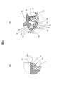
- FIGS. 3A and 3B are an enlarged view of a portion A and an enlarged view of a portion B of the rotary damper 1 shown in FIG. 4A is an enlarged view of a portion C of the rotary damper 1 shown in FIG. 2A, and FIG.
- FIG. 4B is an enlarged view of a portion D of the rotary damper 1 shown in FIG. 2B.
- 5A is a front view of the case 2
- FIG. 5B is a cross-sectional view of the case 2 shown in FIG. 5A
- FIG. It is a rear view.
- 6A and 6B are a front view and a side view of the rotor 3
- FIG. 6C is a DD cross-sectional view of the rotor 3 shown in FIG. 6A.
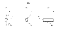
- 7A and 7B are a front view and a rear view of the first sealing material 4
- FIG. 7C is an EE view of the first sealing material 4 shown in FIG. 7A. It is sectional drawing.
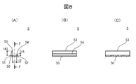
- FIG. 8A and 8B are a front view and a side view of the second sealing material 5, and FIG. 8C is an FF of the second sealing material 5 shown in FIG. 8A.
- FIG. 9A to 9C are a front view, a side view, and a rear view of the lid 6, and FIG. 9D is a cross-sectional view taken along the line GG of the lid 6 shown in FIG. 9A.
- FIG. 10A is a front view of the first and second seal rings 8a and 8b
- FIG. 10B is a cross-sectional view of the first and second seal rings 8a and 8b shown in FIG.
- FIG. 10C is an enlarged view of a portion E of the first and second seal rings 8a and 8b shown in FIG.
- FIG. 10A, and FIG. 10D is a cross-sectional view of FIG. It is F section enlarged view of the 1st, 2nd seal rings 8a and 8b shown in FIG.
- FIG. 11A is a front view of modified examples 8′a and 8′b of the first and second seal rings 8a and 8b
- FIG. 11B is a modified example 8 shown in FIG.
- FIG. 11C is a cross-sectional view taken along the line II of “a, 8′b”
- FIG. FIG. 12 (A) is a side view of a linear motion damper 9 according to another embodiment of the present invention
- FIG. 12 (B) is a side view of J ⁇ of the linear motion damper 9 shown in FIG. 12 (A). It is J sectional drawing.
- FIG. 1A to 1C are a front view, a side view, and a rear view of a rotary damper 1 according to an embodiment of the present invention.
- 2A is a cross-sectional view taken along the line AA of the rotary damper 1 shown in FIG. 1A
- FIG. 2B is a cross-sectional view taken along the line BB of the rotary damper 1 shown in FIG.
- FIG. 3 (A) and 3 (B) are an enlarged view of A part and an enlarged view of B part of the rotary damper 1 shown in FIG. 2 (A)
- FIG. 4 (A) is FIG. 2 (A).
- FIG. 4B is an enlarged view of a part D of the rotary damper 1 shown in FIG. 2B.
- the rotary damper 1 according to the present embodiment is required to brake the rotational motion of a rotating body that rotates in both directions, such as a seat seat with a reclining function used in automobiles, railway vehicles, aircraft, ships, and the like. Used for equipment.
- the rotary damper 1 according to the present embodiment is relative to the fluid holding chamber and the case 2 and the lid 6 that form a fluid holding chamber that holds a viscous fluid (not shown) such as oil and silicone.
- a rotor 3 accommodated in the fluid holding chamber in a rotatable manner.
- FIG. 5A is a front view of the case 2
- FIG. 5B is a cross-sectional view of the case 2 shown in FIG. 5A
- FIG. It is a rear view.
- a cylindrical chamber (cylindrical space with a bottom) 21 having one end opened is formed in the case 2, and the bottom 22 of the cylindrical chamber 21 functions as an opening of a fluid holding chamber.
- a through hole 23 for inserting the rotor 3 is formed.
- the rotor 3 has a lower end 33a (see FIG. 6) of a rotor body 31 (described later) inserted into the through hole 23 so that the rotation shaft 30 of the rotor 3 coincides with the center line 20 of the cylindrical chamber 21. It is accommodated in the cylindrical chamber 21 (see FIG. 2 (A) and FIG. 4 (A)).
- a first seal ring 8 a (described later) attached to the lower end 33 a of the rotor body 31 (refer to FIG. 4A) outward in the axial direction.
- a step 221 that restricts movement is formed.
- the cylindrical chamber 21 protrudes radially inward from the inner peripheral surface 24, and the front end surface 26 is close to an outer peripheral surface 34 (see FIG. 6) of a rotor main body 31 (described later) of the rotor 3.
- a pair of partition portions 25 for partitioning is formed along the center line 20 of the cylindrical chamber 21 so as to be axially symmetric with respect to the center line 20.
- a first sealing material 4 described later is mounted on each of the pair of partition portions 25 (see FIGS. 2B and 4B).
- a female screw portion 27 that is screwed with a male screw portion 62 (see FIG. 9) of the lid 6 to be described later is formed on the opening side 28 of the inner peripheral surface 24 of the cylindrical chamber 21.
- FIG. 6 (A) and 6 (B) are a front view and a side view of the rotor 3, and FIG. 6 (C) is a DD cross-sectional view of the rotor 3 shown in FIG. 6 (A).
- the rotor 3 includes a cylindrical rotor body 31 and a pair of vanes (rotary blades) 32 formed symmetrically with respect to the rotating shaft 30 of the rotor body 31.
- the vane 32 is formed along the rotation axis 30 of the rotor 32, protrudes radially outward from the outer peripheral surface 34 of the rotor body 31, and the tip surface 35 is close to the inner peripheral surface 24 of the cylindrical chamber 21 of the case 2.
- the cylindrical chamber 21 is partitioned.
- the vane 32, together with the partition portion 25 of the cylindrical chamber 21 of the case 2, constitutes a capacity changing unit that compresses one region in the fluid holding chamber partitioned by the vane 32 and expands the other region.
- the vane 32 is formed with a flow path 36 penetrating between both side surfaces 37 a and 37 b of the vane 32 along the rotation direction of the rotor 3.
- the vane 32 is fitted with a second sealing material 5 described later (see FIGS. 2B and 4B).
- the rotor body 31 functions as a resistance generating member that rotates relative to the fluid holding chamber by a rotational force from the outside.
- the rotor body 31 has a lower end 33a rotatably inserted into a through hole 23 formed in the bottom 22 of the cylindrical chamber 21 of the case 2 (see FIGS. 2A and 4A), and an upper end 33b is
- the lid 6 is rotatably inserted into a through-hole 60 (see FIG. 9) described later (see FIGS. 2A, 3A, and 3B).
- an insertion hole 38 for inserting a hexagonal shaft (not shown) for transmitting a rotational force from the outside to the rotor 3 is formed around the rotation shaft 30.
- a first seal ring 8a described later is rotatably mounted on the lower end 33a of the rotor body 31 (see FIG. 4A).
- a step 340 a is formed on the outer peripheral surface 34 of the lower end 33 a of the rotor body 31 to restrict the axial movement of the mounted first seal ring 8 a.
- a second seal ring 8b described later is rotatably mounted on the upper end portion 33b of the rotor body 31 (see FIGS. 3A and 3B).
- a step 340b is formed on the outer peripheral surface 34 of the upper end portion 33b of the rotor body 31 to restrict the axial movement of the mounted second seal ring 8b.
- FIG. 7A and 7B are a front view and a rear view of the first sealing material 4, and FIG. 7C is an EE view of the first sealing material 4 shown in FIG. 7A. It is sectional drawing.
- the first sealing member 4 has a U-shape that can be attached to a partition portion 25 formed in the cylindrical chamber 21 of the case 2, and includes a side wall portion 41 at one end.
- the first sealing member 4 has a bottom portion 40 interposed between the front end surface 26 of the partition portion 25 and the outer peripheral surface 34 of the rotor body 31 of the rotor 3, thereby closing these gaps (see FIG. 4B).
- the side wall portion 41 is interposed between the upper surface 29 of the partition portion 25 and the lower surface 63 of the lid 6 described later, thereby closing these gaps (see FIG. 3A).
- the first sealing material 4 is disposed between the relatively rotating case 2 and the rotor 3, it is preferable to use a resin having excellent slidability such as polyamide as the material.
- FIG. 8A and 8B are a front view and a side view of the second sealing material 5, and FIG. 8C is an FF of the second sealing material 5 shown in FIG. 8A. It is sectional drawing.
- the second sealing material 5 has a U-shape that can be attached to the vane 32 of the rotor 3, and is longer than the width t ⁇ b> 1 (see FIG. 6A) of the vane 32 in the rotation direction.
- a bottom 50 having t2 and a width t4 which is formed integrally with one end 51 of the bottom 50 and longer than the radial width t3 (see FIG. 6B) of the flow path 36 formed in the vane 32.
- a first leg portion 53 having a width t5 that is formed integrally with the other end portion 52 of the bottom portion 50 and is shorter than a radial width t3 of the flow path 36 formed in the vane 32.
- the second sealing material 5 mounted on the vane 32 closes these gaps by the bottom 50 being interposed between the tip surface 35 of the vane 32 and the inner peripheral surface 24 of the cylindrical chamber 21 of the case 2 (see FIG. 4 (B)). Further, as shown in FIG. 2B, when the rotor 3 rotates in the first rotation direction R1 relative to the cylindrical chamber 21 of the case 2, the first leg portion 53 of the second seal material 5 becomes the vane 32. The flow path 36 formed in the vane 32 is closed. On the other hand, when the rotor 3 rotates relative to the cylindrical chamber 21 of the case 2 in the second rotational direction R2, which is the reverse rotational direction of the first rotational direction R1, the first leg portion 53 of the second sealing material 5 is vane. The second leg 54 abuts on the other side surface 37b of the vane 32, and the flow path 36 formed in the vane 32 is opened (see FIG. 4B).
- the 2nd sealing material 5 is arrange
- FIG. 9A to 9C are a front view, a side view, and a rear view of the lid 6, and FIG. 9D is a cross-sectional view taken along the line GG of the lid 6 shown in FIG. 9A. It is.
- the lid 6 has a through hole 60 for inserting the rotor 3 that functions as an opening of the fluid holding chamber at a position facing the through hole 23 formed in the bottom 22 of the cylindrical chamber 21 of the case 2. Is formed.
- the upper end portion 33 b of the rotor body 31 of the rotor 3 is inserted into the through hole 60. Further, on the inner peripheral surface 64 of the through hole 60, movement of the second seal ring 8b (described later) attached to the upper end portion 33b of the rotor body 31 (see FIG. 3A) outward in the axial direction is restricted.
- a step 65 is formed.
- the lower surface 63 of the lid 6 forms a gap g between the upper surface 39 of the vane 32 of the rotor 3 and functioning as a flow path for the viscous fluid filled in the cylindrical chamber 21 (see FIG. 3B). .
- the outer peripheral surface 61 of the lid 6 is formed with a male screw portion 62 that is screwed with the female screw portion 27 formed on the opening side 28 of the inner peripheral surface 24 of the cylindrical chamber 21.
- a groove 66 for mounting the O-ring 7 is formed in the circumferential direction. The O-ring 7 is mounted in the groove 66 and interposed between the outer peripheral surface 61 of the lid 6 and the inner peripheral surface 24 of the cylindrical chamber 21, and the male screw portion 62 of the lid 6 and the female screw portion 27 of the cylindrical chamber 21. The viscous fluid is prevented from leaking to the outside from the threaded portion (see FIGS. 3A and 3B).
- FIG. 10A is a front view of the first and second seal rings 8a and 8b
- FIG. 10B is a cross-sectional view of the first and second seal rings 8a and 8b shown in FIG.
- FIG. 10C is an enlarged view of a portion E of the first and second seal rings 8a and 8b shown in FIG. 10A
- FIG. 10D is a cross-sectional view of FIG. It is F section enlarged view of the 1st, 2nd seal rings 8a and 8b shown in FIG.
- the first seal ring 8a and the second seal ring 8b are annular members formed of an elastic body such as nitrile butadiene rubber (NBR).
- NBR nitrile butadiene rubber
- the first seal ring 8 a and the second seal ring 8 b include an inner peripheral side annular portion 81 having a rectangular cross section, an outer peripheral side annular portion 82 having a rectangular cross section, and a connecting portion 83.
- the inner peripheral side annular portion 81 has an inner peripheral surface 84 having a flat width t6 in the direction of the center line 80 coinciding with the center line 20 of the cylindrical chamber 21 of the case 2. Since the inner peripheral surface 84 has a flat width t6 in the direction of the center line 80, contact between the inner peripheral surface 84 and the mating surface when the first seal ring 8a and the second seal ring 8b are elastically deformed in the radial direction. A change in area can be suppressed.
- the inner peripheral surface 84 is in pressure contact with the outer peripheral surface 34 of the lower end portion 33a of the rotor body 31 of the rotor 3 in the first seal ring 8a, and the upper end portion 33b of the rotor body 31 of the rotor 3 in the second seal ring 8b.
- the outer peripheral surface 34 is pressed against.
- a grease groove 86 is formed in the circumferential direction on the inner peripheral surface 84, and the grease groove 86 is filled with grease.
- the outer peripheral side annular portion 82 has an outer peripheral surface 85 having a flat width t7 in the direction of the center line 80 coinciding with the center line 20 of the cylindrical chamber 21 of the case 2. Since the outer peripheral surface 85 has a flat width t7 in the direction of the center line 80, the contact area between the outer peripheral surface 85 and the mating surface when the first seal ring 8a and the second seal ring 8b are elastically deformed in the radial direction. Change can be suppressed.
- the outer peripheral surface 85 is in pressure contact with the inner peripheral surface 220 of the through hole 23 of the cylindrical chamber 21 of the case 2 in the first seal ring 8a, and the inner peripheral surface of the through hole 60 of the lid 6 in the second seal ring 8b. 64.
- the width t6 of the inner peripheral surface 84 of the inner peripheral ring portion 81 is narrower than the width t7 of the outer peripheral surface 85 of the outer peripheral ring portion 82.
- the frictional resistance of the inner peripheral surface 84 of the inner peripheral side annular portion 81 is smaller than the frictional resistance of the outer peripheral surface 85 of the outer peripheral side annular portion 82. Therefore, when the rotor 3 rotates relative to the cylindrical chamber 21 of the case 2, the inner peripheral surface 84 of the inner peripheral side annular portion 81 having a low friction coefficient is in contact with the inner peripheral surface 84 of the rotor 3.
- the connecting part 83 is arranged between the inner peripheral side annular part 81 and the outer peripheral side annular part 82 and connects both. Further, the connecting portion 83 has a width t ⁇ b> 8 that is narrower than the inner circumferential side annular portion 81 and the outer circumferential side annular portion 82 in the direction of the center line 80. For this reason, when stress is applied to the first seal ring 8a and the second seal ring 8b, the connecting portion 83 is elastically deformed and absorbs the stress, whereby the inner peripheral ring portion 81 and the outer peripheral ring Elastic deformation of the portion 82 is suppressed.
- the movement of the viscous fluid filled in the cylindrical chamber 21 is limited only through the gap g between the lower surface 63 of the lid 6 and the upper surface 38 of the vane 32 of the rotor 3 (see FIG. 3B).
- segmented by the partition part 25 located in the 1st rotation direction R1 side with respect to the vane 32 and the vane 32 increases. For this reason, a strong braking torque is generated.
- a flat width t7 is provided between the through hole 23 of the cylindrical chamber 21 of the case 2 and the lower end portion 33a of the rotor body 31 of the rotor 3 in the direction of the center line 20 of the cylindrical chamber 21,
- An outer peripheral surface 85 that is in pressure contact with the inner peripheral surface 220 of the through hole 23 and an inner periphery that has a flat width t6 in the direction of the center line 20 of the cylindrical chamber 21 and presses against the outer peripheral surface 34 of the lower end portion 33a of the rotor body 31.
- the elastic first seal ring 8a including the surface 84 is disposed, and is flat in the direction of the center line 20 of the cylindrical chamber 21 between the through hole 60 of the lid 6 and the upper end portion 33b of the rotor body 31.
- a second seal ring made of an elastic material, It is arranged 8b.
- the rotor 3 is displaced and the first and second seal rings 8a and 8b
- the contact area between the first seal ring 8a and the lower end 33a of the rotor body 31, the contact area between the first seal ring 8a and the through hole 23 of the cylindrical chamber 21, and the second seal ring 8b when elastically deformed in the radial direction.
- the contact area between the upper end portion 33b of the rotor body 31 and the contact area between the second seal ring 8b and the through hole 60 of the lid 6 can be suppressed.
- the width t6 of the inner peripheral surface 84 of the first and second seal rings 8a and 8b is made narrower than the width t7 of the outer peripheral surface 85. For this reason, when the frictional resistance of the inner peripheral surface 84 is smaller than the frictional resistance of the outer peripheral surface 85 and the rotor 3 rotates relative to the cylindrical chamber 21 of the case 2, the counterpart on the inner peripheral surface 84 having a low friction coefficient. Sliding with the surface (the first seal ring 8a corresponds to the outer peripheral surface 34 of the lower end portion 33a of the rotor main body 31, and the second seal ring 8b corresponds to the outer peripheral surface 34 of the upper end portion 33b of the rotor main body 31).
- the outer peripheral surface 85 having a high friction coefficient corresponds to the mating surface (in the first seal ring 8a, the inner peripheral surface 220 of the through hole 23 of the cylindrical chamber 21 and in the second seal ring 8b, the inner periphery of the through hole 60 of the lid 6).
- the surface 64 is in contact) and does not slide. Therefore, since sliding with the mating surface occurs only on the inner peripheral surface 84 with a short peripheral length, the wear amount of the first seal ring 8a and the second seal ring 8b can be reduced and the life can be extended.
- the grease grooves 86 are formed in the circumferential direction on the inner peripheral surfaces 84 of the first and second seal rings 8a and 8b, and the grease grooves 86 are filled with grease. For this reason, the friction resistance between the first and second seal rings 8a and 8b and the rotor 3 can be reduced, and the rotor 3 can be slid more smoothly.
- the first and second seal rings 8 a and 8 b are the inner peripheral side annular portion 81 having a rectangular cross section including the inner peripheral surface 84 and the outer peripheral side having a rectangular cross section including the outer peripheral surface 85.
- An annular portion 82, and a connecting portion 83 that connects the inner peripheral annular portion 81 and the outer peripheral annular portion 82, and the connecting portion 83 is in the direction of the center line 20 of the cylindrical chamber 21.
- the inner circumferential side annular portion 81 and the outer circumferential side annular portion 82 have a narrower width t8.
- the connecting portion 82 is elastically deformed and absorbs the stress, whereby the inner circumferential side annular portion 81 and the outer circumferential side annular portion 82 is suppressed, the contact area between the first seal ring 8a and the lower end 33a of the rotor body 31, the contact area between the first seal ring 8a and the through hole 23 of the cylindrical chamber 21, and the second seal ring 8b. Changes in the contact area with the upper end portion 33b of the rotor body 31 and the contact area between the second seal ring 8b and the through hole 60 of the lid 6 can be further suppressed.
- the first seal ring 8a attached to the lower end 33a of the rotor body 31 of the rotor 3 on the inner peripheral surface 220 of the through hole 23 of the cylindrical chamber 21 of the case 2 is axially outward. Is formed on the outer peripheral surface 34 of the lower end portion 33a of the rotor body 31 and a step 340a is formed that restricts the movement of the mounted first seal ring 8a in the axially inward direction. Yes. Thereby, the movement to the axial direction of the 1st seal ring 8a with which the lower end part 33a of the rotor main body 31 was mounted
- the second seal ring 8b mounted on the upper end portion 33b of the rotor body 31 of the rotor 3 is moved outward in the axial direction on the inner peripheral surface 64 of the through hole 60 of the lid 6.
- a step 65 for restricting is formed, and a step 340 b for restricting movement of the attached second seal ring 8 b in the axially inward direction is formed on the outer peripheral surface 34 of the upper end portion 33 b of the rotor body 31.
- the first and second sealing materials 4 and 5 are made of a resin having excellent slidability, such as polyamide, so that the first and second sealing materials 4 and 5 are made of the rotor 3. Since it functions as a sliding bearing that slidably supports the outer peripheral surface 34 of the rotor body 31, it absorbs rattling caused by eccentricity of the hexagonal shaft that transmits the rotational force from the outside to the rotor 3, thereby smoothing the hexagonal shaft. Can be rotated.
- the inner peripheral side annular portion 81 including the inner peripheral surface 84 and the outer periphery including the outer peripheral surface 85 are rectangular.
- the first and second seal rings 8a and 8b include an inner peripheral surface 84 having a width t6 in the direction of the center line 20 of the cylindrical chamber 21, and an outer peripheral surface 85 having a width t7 in the direction of the center line 20 of the cylindrical chamber 21.
- it may be an annular member having an inner peripheral surface 84 and an outer peripheral surface 85 having a rectangular cross section.
- the width t6 of the inner peripheral surface 84 of the first and second seal rings 8a, 8b is made narrower than the width t7 of the outer peripheral surface 85, and the inner peripheral surface 84 slides with the mating surface. Is caused.
- the present invention is not limited to this.
- the width t7 of the outer peripheral surface 85 of the first and second seal rings 8a, 8b may be narrower than the width t6 of the inner peripheral surface 84, and the outer peripheral surface 85 may slide with the mating surface.
- the width t6 of the inner peripheral surface 84 and the width t7 of the outer peripheral surface 85 of the first and second seal rings 8a and 8b are the same, and sliding with the mating surface is performed on both the inner peripheral surface 84 and the outer peripheral surface 85. May be generated.
- the grease grooves 86 are formed in the circumferential direction on the inner peripheral surfaces 84 of the first and second seal rings 8a and 8b, and the grease grooves 86 are filled with grease.
- the present invention is not limited to this.
- a grease groove is formed in the circumferential direction on at least one of the inner peripheral surface 84 and the outer peripheral surface 85 of the first and second seal rings 8a and 8b that slide with the mating surface, and the grease groove is filled with grease. That's fine.
- the inner peripheral surface 84 and the outer peripheral surface 85 of 1st, 2nd seal ring 8a, 8b are made into the flat surface in the direction of the centerline 20 of the cylindrical chamber 21, this invention is It is not limited to this.
- the inner peripheral surface 84 and the outer peripheral surface 85 of the first and second seal rings 8 a, 8 b may have any width in the direction of the center line 20 of the cylindrical chamber 21.
- FIG. 11A is a front view of modified examples 8′a and 8′b of the first and second seal rings 8a and 8b
- FIG. 11B is a modified example 8 shown in FIG.
- FIG. 11C is a cross-sectional view taken along the line II of “a, 8′b”
- FIG. 11C is an enlarged view of the G portion of the modified examples 8′a, 8′b shown in FIG.
- these modified examples 8'a and 8'b are annular members formed of an elastic body such as nitrile butadiene rubber, and the modified examples of the first seal ring 8a.
- the inner diameter d1 smaller than the outer diameter d4 of the lower end portion 33a of the rotor body 31 of the rotor 3 and the outer diameter larger than the inner diameter (outer diameter of the step 221) d3 of the through hole 23 of the cylindrical chamber 21 of the case 2.
- the modified example 8′b of the second seal ring 8b the inner diameter d1 smaller than the outer diameter d5 of the upper end portion 33b of the rotor body 31 of the rotor 3 and the inner diameter of the through hole 60 of the lid 6 (
- the outer diameter d2 of the step 65 is larger than the outer diameter d6.
- the modified examples 8 ′ a and 8 ′ b include an inner peripheral surface 84 ′ having a width t ⁇ b> 6 in the direction of the center line 80 and an outer peripheral surface 85 ′ having a width t ⁇ b> 7 in the direction of the center line 80.
- the width t6 of the inner peripheral surface 84 'and the width t7 of the outer peripheral surface 85' are the same, but they may be different.
- the inner peripheral surface 84 ′ has a radius r1 longer than half of the radial width t9 of the modified examples 8′a and 8′b in the direction of the center line 80 coinciding with the center line 20 of the cylindrical chamber 21 of the case 2.
- the modified example 8′a of the first seal ring 8a it is in pressure contact with the outer peripheral surface 34 of the lower end portion 33a of the rotor body 31 of the rotor 3, and the modified example 8′b of the second seal ring 8b. Is pressed against the outer peripheral surface 34 of the upper end portion 33 b of the rotor body 31 of the rotor 3.
- the outer peripheral surface 85 ′ is an arcuate surface having a radius r2 longer than half of the radial width t9 of the modified examples 8′a and 8′b in the direction of the center line 80, and the first seal In the modified example 8′a of the ring 8a, the inner surface 220 of the through hole 23 of the cylindrical chamber 21 of the case 2 is pressed, and in the modified example 8′b of the second seal ring 8b, the inner diameter of the through hole 60 of the lid 6 is increased. Press contact with the peripheral surface 64.
- the curvatures of the inner peripheral surface 84 ′ and the outer peripheral surface 85 ′ can be made smaller than those of O-rings that can replace the modified examples 8 ′ a and 8 ′ b. Therefore, when the modified examples 8′a and 8′b are elastically deformed in the radial direction, changes in the contact area between the inner peripheral surface 84 ′ and the outer peripheral surface 85 ′ and the mating surface can be suppressed, and the sealing performance Can be improved.
- the present invention is not limited to this. As long as the number of the partition portions 25 formed in the cylindrical chamber 21 and the number of vanes 32 formed in the rotor 3 are the same, one or three or more may be formed.
- the second sealing material 5 attached to the vane 32 has a check valve function for opening and closing the flow path 36 formed in the vane 32. It is not limited to.
- a check valve that opens the flow path 36 formed in the vane 32 may be provided separately from the second seal material 5 when the second seal material 5 is rotated.
- the flow path 36 is formed in the vane 32 so as to penetrate the both side surfaces 37a and 37b of the vane 32 along the rotation direction of the rotor 3.
- the present invention is not limited to this.
- a flow path that penetrates both side surfaces of the partition portion 25 along the rotation direction of the rotor 3 may be formed in the partition portion 25.
- the rotor 3 rotates relative to the cylindrical chamber 21 in the first rotation direction R ⁇ b> 1
- the flow path formed in the partition portion 25 is blocked, and the rotor 3 is second relative to the cylindrical chamber 21.
- a check valve that opens the flow path formed in the partition portion 25 may be provided.
- the first seal material 4 has the same shape as the second seal material 5, that is, a bottom portion having a width longer than the circumferential width of the inner peripheral edge of the partition portion 25, and a bottom portion.
- the first seal member 4 may have a function as a check valve that abuts the other side surface of the partition portion 25 and opens the flow path formed in the partition portion 25.
- the second sealing material 5 can be any material as long as it can block the gap between the tip surface 35 of the vane 32 and the inner peripheral surface 24 of the cylindrical chamber 21. Any shape may be used.
- the female screw portion 27 is formed on the opening side 28 of the inner peripheral surface 24 of the cylindrical chamber 21, and the male screw portion that is screwed with the female screw portion 27 on the outer peripheral surface 61 of the lid 6.
- the lid 6 is attached to the case 2 by forming 62.
- the present invention is not limited to this.
- the lid 6 may be attached to the case 2 with a bolt or may be attached with a rivet. Or you may attach by welding, an adhesive agent, etc.
- the rotor 3 is rotated relative to the cylindrical chamber 21 of the case 2 by applying a rotational force to the rotor 3 from the outside.
- the rotor 3 may be rotated relative to the cylindrical chamber 21 of the case 2 by applying a rotational force to the case 2 from the outside.
- the present invention when the rotor 3 rotates in the first rotation direction R1 relative to the cylindrical chamber 21, the rotor 3 moves in the second rotation direction R2 relative to the cylindrical chamber 21.
- a so-called unidirectional rotary damper that generates a braking torque stronger than that in the case of rotation has been described as an example.
- the present invention is not limited to this.
- the movement resistance of the viscous fluid flowing through the flow path formed in the vane 32 or the partition 25 (difficult to move the viscous fluid through the flow path).
- the present invention can also be applied to a so-called bidirectional rotary damper that generates a braking torque according to the property.
- the second sealing material 5 does not need a check valve function.
- the second seal member 5 may be any member that can close the gap between the tip surface 35 of the vane 32 and the inner peripheral surface 24 of the cylindrical chamber 21.
- the rotary damper 1 that generates a braking torque against a rotational force applied from the outside by restricting the movement of the viscous fluid has been described as an example.
- the present invention is not limited to this.
- the present invention is widely applicable to a damper that generates a braking force against an external force by limiting the movement of the viscous fluid.
- FIG. 12 (A) is a side view of a linear motion damper 9 according to another embodiment of the present invention
- FIG. 12 (B) is a side view of J ⁇ of the linear motion damper 9 shown in FIG. 12 (A). It is J sectional drawing.
- the direct acting damper 9 is used for a device that needs to brake the linear motion of a moving body, such as a chair with a height adjustment function, a movable shelf, and the like.
- the direct acting damper 9 includes a case 920 and a lid 960 that form a fluid holding chamber that holds a viscous fluid (not shown) such as oil or silicone, and a direction of a center line 902 with respect to the fluid holding chamber. And a shaft 930 accommodated in the fluid holding chamber so as to be relatively linearly movable.
- a cylindrical chamber (bottomed cylindrical space) 921 having an open end is formed in the case 920, and an insertion hole 923 for inserting the shaft 930 is formed in the bottom 922 of the cylindrical chamber 921.
- the shaft 930 has a cylindrical chamber 921 so that the center line 903 of the shaft 930 coincides with the center line 902 of the cylindrical chamber 921 by inserting one end 933a of a shaft main body 931 described later into the insertion hole 923. Housed inside.
- a mounting portion 927 for mounting the first seal ring 980a is formed in an annular groove shape on the inner peripheral surface 929 of the insertion hole 923.
- an air vent through hole 926 is formed at the bottom 925 of the insertion hole 923.
- a lid 960 is attached to the opening side 928 of the inner peripheral surface 924 of the cylindrical chamber 921 by screwing, bonding, welding, screwing, screwing, or the like.
- the shaft 930 includes a columnar shaft main body 931 and a flange 932 formed near the center of the shaft main body 931.
- the flange 932 projects radially outward from the outer peripheral surface 934 of the shaft main body 931 near the center of the shaft main body 931, and the tip end surface 935 is close to the inner peripheral surface 924 of the cylindrical chamber 921 of the case 920, so that the cylindrical chamber 921 Partition.
- the flange 932 constitutes a capacity changing means that compresses one area in the fluid holding chamber partitioned by the flange 932 and expands the other area in accordance with the linear motion of the shaft 930 in the direction of the center line 903. Further, the flange 932 is formed with a flow path 936 that penetrates between both side surfaces 937 a and 937 b of the flange 932 along the direction of the center line 903 of the shaft 930.
- the shaft body 931 functions as a resistance generating member that moves in the direction of the center line 902 of the cylindrical chamber 921 relative to the fluid holding chamber by an external force in the direction of the center line 903 of the shaft 930.
- the shaft main body 931 has one end 933a side inserted into an insertion hole 923 formed in the bottom 922 of the cylindrical chamber 921 of the case 920 so as to be movable in the direction of the center line 902 of the cylindrical chamber 921, and the other end.
- the 933b side is inserted into the through hole 961 of the lid 960 so as to be movable in the direction of the center line 902 of the cylindrical chamber 921.
- the first seal ring 980a is slidably attached to the shaft body 931 at one end 933a of the shaft 931.
- a second seal ring 980 b is slidably attached to the shaft body 931 at the other end 933 b of the shaft body 931.
- a through hole 961 for inserting a shaft 930 that functions as an opening of the fluid holding chamber is formed in the lid 960 at a position facing the insertion hole 923 formed in the bottom 922 of the cylindrical chamber 921 of the case 920.
- the other end 933 b of the shaft main body 931 of the shaft 930 is inserted into the through hole 961.
- a mounting portion 962 for mounting the second seal ring 980b is formed in an annular groove shape on the inner peripheral surface 964 of the through hole 961.
- First and second seal rings 980a and 980b are annular members formed of an elastic body such as nitrile butadiene rubber.
- the first seal ring 980a has a width in the direction of the center line 902 of the cylindrical chamber 921, and has an inner peripheral surface that is slidably pressed against the outer peripheral surface 934 of the shaft body 931, and the direction of the center line 902 of the cylindrical chamber 921. And an outer peripheral surface that comes into pressure contact with the groove bottom of the mounting portion 927 formed on the inner peripheral surface 929 of the insertion hole 923 of the case 920.
- the second seal ring 980 b has a width in the direction of the center line 902 of the cylindrical chamber 921, an inner peripheral surface that is slidably pressed against the outer peripheral surface 934 of the shaft body 931, and the center line 902 of the cylindrical chamber 921. And an outer peripheral surface that is in pressure contact with the groove bottom of the mounting portion 962 formed on the inner peripheral surface 964 of the through hole 961 of the lid 960.
- the first and second seal rings 980a and 980b include, for example, the first and second seal rings 8a and 8b shown in FIG. 10, or the first and second seal rings 8a and 8b shown in FIG. Examples 8′a, 8′b, etc. can be used.
- the check valve 970 closes flow path 936. Therefore, the movement of the viscous fluid filled in the cylindrical chamber 921 is limited only through the gap g ′ between the outer peripheral surface 935 of the flange 932 of the shaft 930 and the inner peripheral surface 924 of the cylindrical chamber 921, and the flange 930 On the other hand, the pressure with respect to the viscous fluid in the area 921a on the first movement direction L1 side is increased. For this reason, a strong braking torque is generated.
- the check valve 970 opens the flow path 936.
- the movement of the viscous fluid filled in the cylindrical chamber 921 causes the flow path 936 formed in the flange 932 in addition to the gap g ′ between the outer peripheral surface 935 of the flange 932 and the inner peripheral surface 924 of the cylindrical chamber 921. Therefore, the pressure against the viscous fluid in the region 921b on the second movement direction L2 side with respect to the flange 930 is such that the shaft 930 moves in the first movement direction L1 relative to the cylindrical chamber 921 of the case 920. It will not be higher than the case. For this reason, a weaker braking torque is generated than when the shaft 930 moves relative to the cylindrical chamber 921 of the case 920 in the first movement direction L1.
- the flat width in the direction of the center line 902 of the cylindrical chamber 921 is between the insertion hole 923 of the cylindrical chamber 921 of the case 920 and one end 933 a of the shaft main body 931 of the shaft 930.
- a first seal ring 980a having an outer peripheral surface in pressure contact with a groove bottom of the formed mounting portion 927 is disposed, and a cylinder is formed between the through hole 961 of the lid 960 and the other end portion 933b of the shaft body 931.
- the chamber 921 has a width in the direction of the center line 902, has an inner peripheral surface that is slidably pressed against the outer peripheral surface 934 of the shaft body 931, and has a width in the direction of the center line 902 of the cylindrical chamber 921. of It is arranged and the outer circumferential surface of the groove bottom and pressing the mounting portion 962 formed on the inner peripheral surface 964 of the hole 961, the second seal ring 980b having.
- the shaft 930 is displaced, and the first and second seal rings 980a and 980b have a diameter.
- the contact area with the bottom, the contact area between the second seal ring 980b and the other end 933b of the shaft body 931, and the groove bottom of the mounting portion 962 formed in the through hole 961 of the second seal ring 980b and the lid 960 The change of the contact area with can be suppressed. Thereby, the sealing performance between the insertion hole 923 of the cylindrical chamber 921 and one end 933a of the shaft main body 931 and between the through hole 961 of the lid 960 and the other end 933b of the shaft main body 931 is stable. Thus, it is possible to reduce the possibility that the viscous fluid filled in the cylindrical chamber 921 leaks from these gaps.
Landscapes
- Engineering & Computer Science (AREA)
- General Engineering & Computer Science (AREA)
- Mechanical Engineering (AREA)
- Fluid-Damping Devices (AREA)
- Sealing Devices (AREA)
- Gasket Seals (AREA)
Abstract
La présente invention concerne un amortisseur dans lequel toute fuite d'un fluide visqueux qui remplit une chambre de cylindre circulaire est évitée de manière fiable. Un amortisseur rotatif (1) comprend : un premier anneau d'étanchéité (8a) qui comprend un corps élastique, placé entre un orifice traversant (23) dans une chambre de cylindre circulaire (21) à l'intérieur d'un boîtier (2) et l'extrémité inférieure du corps de rotor d'un rotor (3), comprenant une surface périphérique externe ayant une largeur dans la direction de l'axe central de la chambre de cylindre circulaire (21) et en contact de pression avec la surface périphérique interne de l'orifice traversant (23), et comprenant en outre une surface périphérique interne ayant une largeur dans la direction de l'axe central de la chambre de cylindre circulaire (21) et en contact de pression avec la surface périphérique externe de l'extrémité inférieure du corps de rotor ; et un second anneau d'étanchéité (8b) qui comprend un corps élastique, placé entre un orifice traversant (60) dans un couvercle (6) et l'extrémité supérieure du corps de rotor, comprenant une surface périphérique externe ayant une largeur dans la direction de l'axe central de la chambre de cylindre circulaire (21) et en contact de pression avec la surface périphérique interne de l'orifice traversant (60), et comprenant en outre une surface périphérique interne ayant une largeur dans la direction de l'axe central de la chambre de cylindre circulaire (21) et en contact de pression avec la surface périphérique externe de l'extrémité supérieure du corps de rotor.
Priority Applications (4)
| Application Number | Priority Date | Filing Date | Title |
|---|---|---|---|
| EP17813327.8A EP3473884B1 (fr) | 2016-06-15 | 2017-06-13 | Amortisseur |
| CN201780036686.1A CN109312804B (zh) | 2016-06-15 | 2017-06-13 | 阻尼器 |
| CA3025485A CA3025485C (fr) | 2016-06-15 | 2017-06-13 | Amortisseur |
| US16/309,579 US10900536B2 (en) | 2016-06-15 | 2017-06-13 | Damper |
Applications Claiming Priority (2)
| Application Number | Priority Date | Filing Date | Title |
|---|---|---|---|
| JP2016-119417 | 2016-06-15 | ||
| JP2016119417A JP7042019B2 (ja) | 2016-06-15 | 2016-06-15 | ダンパ |
Publications (1)
| Publication Number | Publication Date |
|---|---|
| WO2017217432A1 true WO2017217432A1 (fr) | 2017-12-21 |
Family
ID=60664640
Family Applications (1)
| Application Number | Title | Priority Date | Filing Date |
|---|---|---|---|
| PCT/JP2017/021875 Ceased WO2017217432A1 (fr) | 2016-06-15 | 2017-06-13 | Amortisseur |
Country Status (6)
| Country | Link |
|---|---|
| US (1) | US10900536B2 (fr) |
| EP (1) | EP3473884B1 (fr) |
| JP (2) | JP7042019B2 (fr) |
| CN (1) | CN109312804B (fr) |
| CA (1) | CA3025485C (fr) |
| WO (1) | WO2017217432A1 (fr) |
Families Citing this family (5)
| Publication number | Priority date | Publication date | Assignee | Title |
|---|---|---|---|---|
| JP7075749B2 (ja) * | 2017-12-08 | 2022-05-26 | オイレス工業株式会社 | ダンパ |
| US11072958B2 (en) * | 2018-08-07 | 2021-07-27 | Kem Hongkong Limited | Damper hinge and western-style toilet using the same |
| JP7391823B2 (ja) * | 2020-11-19 | 2023-12-05 | オイレス工業株式会社 | ロータリダンパ |
| CN114151505B (zh) * | 2021-11-11 | 2025-12-02 | 佳乐电子科技(广东)有限公司 | 一种阻尼器 |
| CN114688197A (zh) * | 2022-03-09 | 2022-07-01 | 佳乐电子科技(广东)有限公司 | 一种阻尼器 |
Citations (8)
| Publication number | Priority date | Publication date | Assignee | Title |
|---|---|---|---|---|
| JPS4729195Y1 (fr) * | 1966-07-11 | 1972-09-01 | ||
| JPS6249056U (fr) * | 1985-09-17 | 1987-03-26 | ||
| JPH03114602U (fr) * | 1990-03-07 | 1991-11-26 | ||
| JP2003506256A (ja) * | 1999-08-05 | 2003-02-18 | 株式会社ニフコ | オイル式筒形回転ダンパ |
| JP2005030537A (ja) * | 2003-07-10 | 2005-02-03 | Kayaba Ind Co Ltd | シール部材およびガススプリング |
| JP2006153034A (ja) * | 2004-11-25 | 2006-06-15 | Tok Bearing Co Ltd | 回転ダンパ |
| JP2008039084A (ja) * | 2006-08-07 | 2008-02-21 | Nsk Ltd | シール装置およびその製造方法、並びにそれを装着したボールねじ装置とボールスプライン装置 |
| JP2013203280A (ja) * | 2012-03-29 | 2013-10-07 | Panasonic Corp | 自動変速機用コントロールスイッチ |
Family Cites Families (20)
| Publication number | Priority date | Publication date | Assignee | Title |
|---|---|---|---|---|
| US2420039A (en) * | 1945-05-03 | 1947-05-06 | Ramsey Accessories Mfg Corp | Shaft sealing ring |
| US3180650A (en) * | 1963-05-29 | 1965-04-27 | Illinois Milling Inc | Split-ring oil seal with reinforcing element |
| DE2515985A1 (de) | 1975-04-12 | 1976-10-21 | Fichtel & Sachs Ag | Rotationsschwingungsdaempfer |
| DE3244961A1 (de) * | 1982-12-04 | 1984-06-07 | Fichtel & Sachs Ag, 8720 Schweinfurt | Gleitringdichtung |
| JPS60104872A (ja) * | 1983-11-09 | 1985-06-10 | Nippon Pillar Packing Co Ltd | 非常用軸封装置 |
| JPS6249056A (ja) | 1985-08-27 | 1987-03-03 | Kubota Ltd | 四輪駆動型農用トラクタの走行変速構造 |
| JPH0672633B2 (ja) * | 1986-05-23 | 1994-09-14 | 不二精器株式会社 | ロ−タリ−ダンパ |
| JP2545468B2 (ja) | 1989-09-28 | 1996-10-16 | 川崎製鉄株式会社 | ステンレス鋼帯の冷間圧延方法 |
| JP2581655B2 (ja) * | 1991-03-08 | 1997-02-12 | トックベアリング株式会社 | 高トルク用ダンパ |
| DE19636475B4 (de) | 1996-09-07 | 2004-03-04 | Itw-Ateco Gmbh | Rotationsdämpfer |
| JP2000161412A (ja) | 1998-11-25 | 2000-06-16 | Tok Bearing Co Ltd | 回転ダンパ |
| JP4582512B2 (ja) * | 2000-07-19 | 2010-11-17 | トックベアリング株式会社 | 回転ダンパ |
| JP3978340B2 (ja) * | 2002-01-23 | 2007-09-19 | 日本電産サンキョー株式会社 | ダンパ装置 |
| JP4102200B2 (ja) | 2002-01-23 | 2008-06-18 | 日本電産サンキョー株式会社 | 粘性流体を用いたダンパ装置の製造方法 |
| JP4462887B2 (ja) * | 2003-10-06 | 2010-05-12 | トックベアリング株式会社 | 回転ダンパ |
| ITTO20080083U1 (it) | 2008-06-13 | 2009-12-13 | Antonino Cultraro | Smorzatore rotativo del tipo a barilotto |
| JP5702208B2 (ja) * | 2011-03-31 | 2015-04-15 | オイレス工業株式会社 | ロータリダンパ |
| JP5760812B2 (ja) * | 2011-07-28 | 2015-08-12 | オイレス工業株式会社 | トラックのテールゲート用の回転減速装置 |
| JP2014005883A (ja) | 2012-06-25 | 2014-01-16 | Somic Ishikawa Inc | ロータリダンパー |
| JP6480155B2 (ja) * | 2014-11-11 | 2019-03-06 | オイレス工業株式会社 | ロータリダンパ |
-
2016
- 2016-06-15 JP JP2016119417A patent/JP7042019B2/ja active Active
-
2017
- 2017-06-13 CA CA3025485A patent/CA3025485C/fr active Active
- 2017-06-13 CN CN201780036686.1A patent/CN109312804B/zh active Active
- 2017-06-13 WO PCT/JP2017/021875 patent/WO2017217432A1/fr not_active Ceased
- 2017-06-13 US US16/309,579 patent/US10900536B2/en active Active
- 2017-06-13 EP EP17813327.8A patent/EP3473884B1/fr active Active
-
2021
- 2021-03-29 JP JP2021056144A patent/JP7076025B2/ja active Active
Patent Citations (8)
| Publication number | Priority date | Publication date | Assignee | Title |
|---|---|---|---|---|
| JPS4729195Y1 (fr) * | 1966-07-11 | 1972-09-01 | ||
| JPS6249056U (fr) * | 1985-09-17 | 1987-03-26 | ||
| JPH03114602U (fr) * | 1990-03-07 | 1991-11-26 | ||
| JP2003506256A (ja) * | 1999-08-05 | 2003-02-18 | 株式会社ニフコ | オイル式筒形回転ダンパ |
| JP2005030537A (ja) * | 2003-07-10 | 2005-02-03 | Kayaba Ind Co Ltd | シール部材およびガススプリング |
| JP2006153034A (ja) * | 2004-11-25 | 2006-06-15 | Tok Bearing Co Ltd | 回転ダンパ |
| JP2008039084A (ja) * | 2006-08-07 | 2008-02-21 | Nsk Ltd | シール装置およびその製造方法、並びにそれを装着したボールねじ装置とボールスプライン装置 |
| JP2013203280A (ja) * | 2012-03-29 | 2013-10-07 | Panasonic Corp | 自動変速機用コントロールスイッチ |
Non-Patent Citations (1)
| Title |
|---|
| See also references of EP3473884A4 * |
Also Published As
| Publication number | Publication date |
|---|---|
| JP7042019B2 (ja) | 2022-03-25 |
| US10900536B2 (en) | 2021-01-26 |
| CN109312804B (zh) | 2021-03-02 |
| JP2021096001A (ja) | 2021-06-24 |
| US20190331190A1 (en) | 2019-10-31 |
| EP3473884B1 (fr) | 2021-06-02 |
| CA3025485A1 (fr) | 2017-12-21 |
| CN109312804A (zh) | 2019-02-05 |
| EP3473884A4 (fr) | 2020-02-26 |
| JP7076025B2 (ja) | 2022-05-26 |
| JP2017223296A (ja) | 2017-12-21 |
| EP3473884A1 (fr) | 2019-04-24 |
| CA3025485C (fr) | 2024-10-01 |
Similar Documents
| Publication | Publication Date | Title |
|---|---|---|
| JP7076025B2 (ja) | ダンパ | |
| TWI673444B (zh) | 旋轉阻尼器 | |
| US9360078B2 (en) | Hydraulic shock absorber | |
| CN109154350B (zh) | 旋转阻尼器 | |
| EP3321547B1 (fr) | Ensemble de sceau pour élément rotatif | |
| JP7075749B2 (ja) | ダンパ | |
| WO2018056216A1 (fr) | Amortisseur | |
| JP7391823B2 (ja) | ロータリダンパ | |
| JP5273243B2 (ja) | 密封装置 | |
| CN110998153B (zh) | 密封装置 | |
| JP4366176B2 (ja) | ダンパー装置 | |
| JP2017115996A (ja) | ロータリダンパ | |
| JP2007092791A (ja) | シールリング | |
| JP2007247698A (ja) | バックアップリング | |
| JP2015098899A (ja) | 流体流路の接続構造及びこれに用いる密封装置 |
Legal Events
| Date | Code | Title | Description |
|---|---|---|---|
| ENP | Entry into the national phase |
Ref document number: 3025485 Country of ref document: CA |
|
| 121 | Ep: the epo has been informed by wipo that ep was designated in this application |
Ref document number: 17813327 Country of ref document: EP Kind code of ref document: A1 |
|
| NENP | Non-entry into the national phase |
Ref country code: DE |
|
| ENP | Entry into the national phase |
Ref document number: 2017813327 Country of ref document: EP Effective date: 20190115 |