WO2017221454A1 - 光ファイバケーブルの把持方法及び光ファイバケーブル把持具 - Google Patents
光ファイバケーブルの把持方法及び光ファイバケーブル把持具 Download PDFInfo
- Publication number
- WO2017221454A1 WO2017221454A1 PCT/JP2017/005505 JP2017005505W WO2017221454A1 WO 2017221454 A1 WO2017221454 A1 WO 2017221454A1 JP 2017005505 W JP2017005505 W JP 2017005505W WO 2017221454 A1 WO2017221454 A1 WO 2017221454A1
- Authority
- WO
- WIPO (PCT)
- Prior art keywords
- optical fiber
- gripping
- support wire
- fiber cable
- support
- Prior art date
- Legal status (The legal status is an assumption and is not a legal conclusion. Google has not performed a legal analysis and makes no representation as to the accuracy of the status listed.)
- Ceased
Links
Images




Classifications
-
- G—PHYSICS
- G02—OPTICS
- G02B—OPTICAL ELEMENTS, SYSTEMS OR APPARATUS
- G02B6/00—Light guides; Structural details of arrangements comprising light guides and other optical elements, e.g. couplings
- G02B6/44—Mechanical structures for providing tensile strength and external protection for fibres, e.g. optical transmission cables
- G02B6/4401—Optical cables
- G02B6/4429—Means specially adapted for strengthening or protecting the cables
-
- G—PHYSICS
- G02—OPTICS
- G02B—OPTICAL ELEMENTS, SYSTEMS OR APPARATUS
- G02B6/00—Light guides; Structural details of arrangements comprising light guides and other optical elements, e.g. couplings
- G02B6/44—Mechanical structures for providing tensile strength and external protection for fibres, e.g. optical transmission cables
- G02B6/4401—Optical cables
- G02B6/4403—Optical cables with ribbon structure
- G02B6/4404—Multi-podded
-
- G—PHYSICS
- G02—OPTICS
- G02B—OPTICAL ELEMENTS, SYSTEMS OR APPARATUS
- G02B6/00—Light guides; Structural details of arrangements comprising light guides and other optical elements, e.g. couplings
- G02B6/46—Processes or apparatus adapted for installing or repairing optical fibres or optical cables
- G02B6/48—Overhead installation
- G02B6/483—Installation of aerial type
Definitions
- the present invention relates to a method for gripping an optical fiber cable and an optical fiber cable gripper.
- FTTH Fiber-to-the-Home
- FTTH Fiber-to-the-Home
- an aerial optical fiber cable that is laid by holding a support wire on a utility pole or the like is known.
- Patent Document 1 discloses a self-supporting optical fiber cable in which a support wire is formed of a steel wire and is further covered with a jacket. Further, Patent Document 2 discloses a technique for hooking an end portion of a support wire separated from an optical fiber cable around an anchor of the S hardware with respect to an S hardware having a function of holding an aerial optical fiber cable. It is disclosed.
- the object of the present invention is to hold a support line of a non-metallic material while suppressing breakage.
- a main invention for achieving the above object is a method of gripping an optical fiber cable including a main body portion including an optical fiber and a support wire portion using a gripping member, and the support wire portion is made of a metal. Including a support wire made of a material other than the above and a jacket covering the support wire, and holding and gripping the gripping member with respect to the support wire portion while the jacket covers the support wire. This is a method for gripping an optical fiber cable.
- FIG. 1 is a cross-sectional view of the optical fiber cable 1.
- FIG. 2 is a schematic view showing a gripping structure of the optical fiber cable 1 according to the first embodiment of the present invention.
- FIG. 3 is a cross-sectional view of the grip portion 11 as viewed from the longitudinal direction of the support line portion 2.
- FIG. 4 is a view for explaining the detailed structure of the grip 12 for gripping.
- 5A to 5C are diagrams illustrating a method of winding the grip 12 shown in FIG. 4 around the support wire portion 2.
- FIG. 6A and 6B are schematic views showing a holding structure of the optical fiber cable 1 according to the second embodiment of the present invention.
- FIG. 7A is a view showing a structure of an end gripping grip 19 according to the second embodiment of the present invention.
- FIG. 7B is a diagram showing a detailed structure of the end gripping grip 19 when gripping the retracting support line 18.
- FIG. 8A is a longitudinal sectional view when no tension is applied when the support line portion is gripped using the grip for gripping.
- FIG. 8B shows a longitudinal cross-sectional view when tension is applied and delamination occurs at the interface.
- FIG. 9 is a diagram for explaining the test mechanism 21 that measures the adhesion between the outer jacket and the support wire.
- a method for gripping an optical fiber cable including a main body including an optical fiber and a support wire portion using a gripping member, wherein the support wire portion is made of a material other than metal, and the support wire.
- An optical fiber cable gripping method is characterized in that the gripping member is clamped and gripped with respect to the support line portion while the cover covers the support wire while the jacket covers the support wire. Become. According to such a method of gripping an optical fiber cable, it is possible to hold the support line of the nonmetallic material while suppressing breakage.
- the gripping member is tightened so as to be spirally wound around the support line portion. As a result, the gripping member can be gripped more closely to the support line portion.
- the support wire is preferably made of glass fiber reinforced plastic. In such a case, it is particularly advantageous.
- an anti-slip material is included between the gripping member and the jacket. Thereby, in a state where the support line portion is gripped by the gripping member, the gripping member is difficult to come off.
- the gripping member is clamped and gripped with respect to the support line portion to such an extent that the outer cover is not crushed. Thereby, it is possible to suppress the breakage of the support line due to the crushing of the jacket.
- the outer cover integrally covers the main body portion and the support wire to intermittently form a neck portion that connects the main body portion and the support wire. Thereby, it is possible to suppress breakage of the support wire due to wind pressure load even in a long span aerial environment.
- the support wire portion is gripped by a fixed structure in a separation portion where the main body portion and the support wire portion are not connected. Thereby, only a support line is grasped and it is possible to suppress breakage of the optical fiber in the main body.
- the main body portion is loose with respect to the support line portion. Therefore, even if a tensile force is applied to the support wire, it is possible to suppress the breakage of the optical fiber.
- the adhesion force F between the jacket and the support wire is 1.77 ⁇ D [N / mm] or more.
- FIG. 1 is a cross-sectional view of the optical fiber cable 1.
- the optical fiber cable 1 is an aerial optical fiber cable having a self-supporting structure that is used when laying so as to bridge between utility poles in FTTH. Further, the optical fiber cable 1 may be an optical fiber drop cable for branching from an aerial optical fiber cable and drawing the optical fiber into a subscriber's house.
- the optical fiber cable 1 includes a support line portion 2, a main body portion 3, and a neck portion 4.
- the optical fiber cable 1 has a structure in which a support line portion 2 and a main body portion 3 are connected via a neck portion 4.
- the support line part 2 is a suspension line for aerial use.
- the support line portion 2 includes a support line 5 and a jacket 6A.
- the support wire 5 is formed of a so-called non-metallic material made of a material other than metal.
- Non-metallic materials include, for example, fiber reinforced plastic (FRP) such as glass fiber reinforced plastic (GFRP), aramid fiber reinforced plastic (KFRP) reinforced by Kevlar (registered trademark), polyethylene fiber reinforced plastic reinforced by polyethylene fiber, and the like. used.
- FRP fiber reinforced plastic
- GFRP glass fiber reinforced plastic
- KFRP aramid fiber reinforced plastic
- Kevlar registered trademark
- polyethylene fiber reinforced plastic reinforced by polyethylene fiber and the like.
- a fibrous tensile body such as glass fiber, aramid fiber, or polyethylene fiber may be used in combination with any one of the above-mentioned fiber reinforced plastics (FRP).
- the outer cover 6A is a covering material that covers the support wire 5.
- the jacket 6A is made of a thermoplastic resin.
- thermoplastic resin materials generally used for optical fiber cables such as polyethylene, polypropylene, polystyrene, polyvinyl chloride, and the like are used.
- the main body 3 includes an optical fiber 9, a pair of strength members 7, a pair of separators 8, and a jacket 6B.
- the optical fiber 9, the pair of strength members 7, and the pair of separators 8 are arranged in a positional relationship as illustrated.
- the optical fiber 9 and the pair of strength members 7 are arranged in parallel to each other in the longitudinal direction. However, if the structure of the main-body part 3 is provided with the optical fiber 9, it will not be restricted to this.
- the optical fiber 9 is an optical signal transmission line and is a generic name including an optical fiber core, an optical fiber, an optical fiber cord, and the like. Further, the optical fiber 9 may be constituted by an intermittently fixed type optical fiber ribbon. As a result, the intermittently fixed type optical fiber tape core wire can be rounded into a cylindrical shape (bundle shape) or folded, and a large number of optical fibers 9 can be bundled at a high density. Furthermore, it is easy to take out one or a plurality of optical fibers at the time of intermediate post-branching by being constituted by an intermittently fixed type optical fiber ribbon.
- the pair of strength members 7 have a function of resisting tension in the longitudinal direction of the optical fiber 9 so that the optical fiber 9 is not stretched more than necessary.
- the pair of strength members 7 are disposed outside the left and right ends of the pair of separators 8.
- the pair of strength members 7 may be formed of the same non-metallic material as the support wire 5 or may be formed of a steel wire.
- the pair of separators 8 have a function capable of separating the optical fiber 9 and the jacket 6B.
- the pair of separators 8 surrounds the optical fiber 9, thereby preventing the material of the jacket 6 ⁇ / b> B from adhering to the optical fiber in the manufacturing process of the optical fiber cable 1.
- the pair of separators 8 is formed of a material having a melting point higher than that of the material of the outer cover 6B.
- a nylon flat yarn is used as a material of the pair of separators 8.
- the jacket 6B may be formed of the same material as that of the jacket 6A, or may be formed of a different material.
- the cross-sectional shape of the main body portion 3 covering the outer cover 6 ⁇ / b> B is substantially rectangular.
- a notch 10 having a V-shaped cross section is formed on the long side. Two notches 10 are formed on each side.
- the notch 10 is provided in order to divide and cut the main body 3 and to easily take out the optical fiber 9. Although it is not essential to provide the notch 10 in the main body 3, it is preferable to provide it.
- the neck portion 4 can separate the support wire portion 2 and the main body portion 3 by being cut.
- the neck 4 can be formed of the same material as the outer cover 6A and the outer cover 6B. Furthermore, the neck 4, the outer cover 6A, and the outer cover 6B may be integrally formed of the same material.
- the configuration of the optical fiber cable 1 is not limited to the above-described configuration, and can be various configurations.
- the optical fiber 9 may be composed of 8 to 48 cores, or may be composed of 48 or more cores.
- FIG. 2 is a schematic view showing a gripping structure of the optical fiber cable 1 according to the first embodiment of the present invention.
- a structure in which the optical fiber cable 1 is gripped by each power pole P in order to lay and lay the optical fiber cable 1 between the long-span power poles will be described.
- the support wire portion 2 and the main body portion 3 are connected by a plurality of neck portions 4 that are intermittently arranged in the longitudinal direction. As described above, the connection by the neck 4 connects the support wire portion 2 and the main body portion 3 by integrally forming the neck portion 4, the outer cover 6A, and the outer cover 6B from the same material. Good.
- the support line portion 2 and the main body portion 3 are separated between a pair of adjacent neck portions 4 and 4. At a position where the support wire portion 2 and the main body portion 3 are separated, a grip portion 11 is provided in which only the support wire portion 2 is gripped by the utility pole P.
- the main body portion 3 is provided so as to meander with respect to the support wire portion 2. Thereby, a space is provided between the support wire portion 2 and the main body portion 3, and the wind pressure load applied to the entire optical fiber cable 1 can be reduced.
- the length of the neck 4 in the longitudinal direction of the support line portion is 40 mm
- the length of the separation portion (pitch of the neck 4) is 250 mm or 550 mm
- the distance between the utility poles is several m to It is about 50m.
- these values may be appropriately changed.
- the gripping part 11 has a gripping grip 12 and a fixing member 13.
- the gripping portion 11 has a structure in which the gripping grip 12 grips the support wire portion 2 and the fixing member 13 fixes the support wire portion 2 gripped by the gripping grip 12 to the utility pole P.
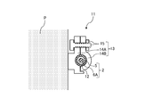
- FIG. 3 is a cross-sectional view of the grip portion 11 as viewed from the longitudinal direction of the support wire portion 2.
- the fixing member 13 constituting the grip portion 11 includes a pair of covers 14A and 14B and a fixing tool 15 (bolts and nuts).
- the cover 14A is fixed to the utility pole P.
- the cover 14 ⁇ / b> A and the cover 14 ⁇ / b> B are provided so as to cover the support line portion 2 and the gripping grip 12, and are fastened by the fixture 15. As a result, the support wire portion 2 and the gripping grip 12 are fixed to the utility pole P.
- the grip grip 12 is provided to grip the support line portion 2 so as to wrap around the outer periphery of the support line portion 2.
- the detailed structure of the grip 12 for gripping will be described later.
- the grip 12 for gripping is attached to the outer periphery of the support line portion 2 while the outer cover 6 ⁇ / b> A covers the support line 5.
- the pressing force of the gripping grip 12 be adjusted to such an extent that the outer cover 6 ⁇ / b> A is not crushed (including breakage).
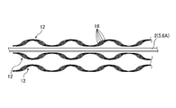
- FIG. 4 is a diagram for explaining the detailed structure of the grip 12 for gripping.
- a structure is shown in which three gripping grips 12 are gripped so as to be spirally wound around the support line portion 2.
- the number of gripping grips 12 that grip one support line portion 2 is not intended to be limited to three, and may be another number.
- the gripping grip 12 is composed of a plurality of strands 16.
- a galvanized steel wire, a zinc aluminum alloy plated steel wire or the like is used as the strand 16.
- the plurality of strands 16 are arranged so as to be adjacent to each other, bonded to each other, and further spirally wound.
- a friction material for increasing the frictional force may be applied to the surface of the plurality of strands 16 wound in a spiral shape in contact with the support wire portion 2.
- the friction material for example, fine sand or glass particles can be used.
- the gripping grip 12 shown in FIG. 4 is composed of five strands, but there is no intention to limit the number of strands constituting the gripping grip to five, and from one flat strand It may be configured.
- FIGS. 5A to 5C are diagrams showing a method of winding the gripping grip 12 shown in FIG.
- subscripts (A to C) may be added to the gripping grip 12, and the gripping grips 12 will be described separately.
- a gripping grip 12 ⁇ / b> A is wound around the support wire portion 2 separated from the main body portion 3.
- the gripping grip 12B and the gripping grip 12C are wound while adjusting the winding pitch of the gripping grip 12A so as to leave room for winding.
- FIG. 5B shows a state in which the gripping grip 12B is wound halfway.
- the gripping grip 12C is wound so as to be adjacent to the gripping grip 12B.
- the support wire portion 2 is clamped and held by pulling the holding grip 12A to the holding grip 12C to both sides so as to extend. Finally, it fixes to the support line part 2 with fixing members, such as a tape not shown.
- the above-described gripping portion 11 has described the method of tightening the gripping grip 12 around the support wire portion 2 in a spiral manner, but the tightening method is not limited to this, tightening by vertical attachment, It may be tightened by winding other than spiral.
- FIGS. 6A and 6B are schematic views showing a gripping structure of the optical fiber cable 1 according to the second embodiment of the present invention.
- FIG. 6A is a diagram for explaining a case where an optical fiber is branched by a utility pole-mounted branch closure 17A and pulled into a subscriber's home Q.
- FIG. 6B is a diagram for explaining a case where an optical fiber is branched by a support line suspension type branch closure 17B and pulled into a subscriber's home Q.
- the utility pole R is provided with a branch closure 17A.
- the branch closure 17A is a box that holds an optical fiber cable and accommodates a connection point when the optical fiber cable is connected, branched, or pulled down.
- a part of the optical fiber 9 of the main body 3 is branched in the branch closure 17A and drawn into the customer's home Q as a new main body 3A.
- the main body 3A is drawn into the subscriber's home Q through the lead-in hole 20 provided in the subscriber's home Q while being supported by the support wire 18 for pull-in after branching.
- the support line 18 for drawing is formed of a non-metallic material and is further covered with a jacket (not shown).
- the retracting support line 18 is fastened by an end gripping grip 19, and one is fixed to the telephone pole R and the other is fixed to the wall of the subscriber's home Q.
- FIG. 6B a branch closure 17 ⁇ / b> B is provided in the support line portion 2.
- Other configurations are the same as those described in FIG. 6A.
- FIG. 7A is a diagram showing a structure of an end grip 19 according to the second embodiment of the present invention.
- the end grip 19 includes a folded portion 21 and two grip portions 22.
- the two grip portions 22 are configured to be connected by the folded portion 21.
- FIG. 7B is a view showing a detailed structure of the end gripping grip 19 when gripping the retracting support line 18.
- the two grip portions 19 of the grip 12 for gripping are gripped so as to be wound around the pull-in support line 18 in a spiral manner.
- the winding method is the same as the method described in FIGS. 5A to 5C (first embodiment).
- the pull-in support wire 18 is locked to the utility pole R by hooking the ring surrounded by the turn-up portion 21 on a catching fixture fixed to the utility pole R or the subscriber's home Q. (See Figures 6A and 6B)
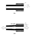
- FIG. 8A shows a longitudinal cross-sectional view when tension is not applied in the case where the support line portion is gripped using the grip for gripping.
- FIG. 8B shows a longitudinal cross-sectional view when tension is applied and delamination occurs at the interface.
- a tension T is applied in the tension direction of the support wire portion 2 under an aerial environment.
- the outer cover 6A with which the gripping grip 12 comes into contact is pulled in the direction of the tension T and extends in the longitudinal direction.
- the thickness of the outer cover 6 ⁇ / b> A decreases with the elongation, and the outer cover 6 ⁇ / b> A acts as a force for peeling from the support wire 5.
- the support line portion 2 between the utility poles does not draw an ideal straight line, but draws a slack line in the direction of gravity. If it does so, the force which is going to peel will appear locally in the vicinity of the area where the pressing force by grip grip 12 on support line part 2 is applied, and it will become easier to cause peeling.
- FIG. 8B shows a phenomenon in which separation at the interface occurs in the vicinity of the region where the pressing force by the gripping grip 12 is applied.
- the pressing force works in a direction to cancel the force to be peeled off, so that peeling at the interface does not occur. Further, the portion where the separation at the interface occurs does not always occur in the vicinity of the region where the pressing force by the gripping grip 12 is applied. In any part of the region where the pressing force by the gripping grip 12 is not applied, peeling at the interface may occur.
- the gripping grip 12 comes into direct contact with the support wire 5. Since the support wire 5 is formed of a non-metallic material, for example, glass fiber reinforced plastic (GFRP) or the like, the support wire 5 is easily broken by the contact of the gripping grip 12 as compared with the case of being formed of a steel wire or the like. End up.
- GFRP glass fiber reinforced plastic
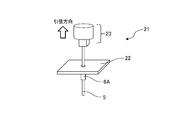
- FIG. 9 is a diagram for explaining the test mechanism 21 that measures the adhesion between the outer jacket and the support wire.
- the test mechanism 21 covers a part of the support wire 5 with an outer cover 6A, and pulls only the support wire 5 with a tension T in the pulling direction in FIG. It is a mechanism that measures the load at the time of drawing.
- adhesion the load at the time of drawing is referred to as adhesion.
- the gripping grips 12 were attached to both ends of the same cables as the prototype cables 1 to 5, and a tensile test was performed.
- the tensile test was performed by measuring the load when the outer cover 6A was broken and the exposure of the support wire 5 was confirmed.
- the load at the time of the break is referred to as a break load.
- the prototype cable 3 had a significantly smaller breaking load after 500 hours than the other prototype cables. Furthermore, the diameter of the prototype cable when the outer cover 6A is covered is designed on the assumption that the maximum wind pressure load (including the time of icing) is applied to about 3200 N, but it is also less than that. Therefore, this prototype cable 3 was rejected, and the remaining prototype cables 1, 2, 4, and 5 were evaluated as acceptable.
Landscapes
- Physics & Mathematics (AREA)
- General Physics & Mathematics (AREA)
- Optics & Photonics (AREA)
- Light Guides In General And Applications Therefor (AREA)
Abstract
【課題】金属以外の材質からなる、いわゆるノンメタリック材料の支持線を電柱等に引き留める際、支持線を被覆する外被を剥いで把持したり、金物のアンカーに巻き掛けて係止しようとすると、支持線が折れてしまうおそれがある。 【解決手段】本発明は、光ファイバを含む本体部と、支持線部とからなる光ファイバケーブルを、把持用部材を用いて把持する方法である。前記支持線部は金属以外の材料からなる支持線と、前記支持線を被覆する外被を含み、前記外被が前記支持線を被覆したまま、前記把持用部材を前記支持線部に対して締め付けて把持する。
Description
本発明は、光ファイバケーブルの把持方法及び光ファイバケーブル把持具に関する。
近年、通信事業者と加入者宅とを直接光ファイバで結んで高速通信サービスを提供するFTTH(Fiber to the Home)サービスが普及している。通信事業者から延線され、電柱間を架け渡すように敷設する光ファイバケーブルとして、支持線を電柱等に引き留めて敷設される架空光ファイバケーブルが知られている。
このような光ファイバケーブルに関連して、特許文献1には、支持線が鋼線で形成され、さらに外被により被覆された自己支持構造の光ファイバケーブルが開示されている。また、特許文献2には、架空光ファイバケーブルの引き留め機能を有するS金物について、光ファイバケーブルと分離された支持線の端部をS金物のアンカーにたすき掛けに巻き掛けて係止する技術が開示されている。
電磁誘導を抑える目的から、特許文献1のような鋼線に代えて、金属以外の材質からなる、いわゆるノンメタリック材料の支持線を導入する需要が高まっている。支持線を電柱等に引き留める際、鋼線でできた支持線の場合であれば、支持線を被覆する外被を剥いで引き留めていた。しかし、ノンメタリック材料の支持線の場合は、引き留め用の把持具が支持線に直接触れることで支持線が破断してしまうおそれがあり、このような引き留め方法をとることはできなかった。また、ノンメタリック材料の支持線を特許文献2のようなS金物のアンカーに巻き掛けて係止しようとすると、支持線が折れてしまうおそれがある。そこで、ノンメタリック材料の支持線について、破断を抑制しつつ引き留める方法が必要となっていた。
本発明は、ノンメタリック材料の支持線について、破断を抑制しつつ引き留めることを目的とする。
上記目的を達成するための主たる発明は、光ファイバを含む本体部と、支持線部とからなる光ファイバケーブルを、把持用部材を用いて把持する方法であって、前記支持線部は、金属以外の材料からなる支持線と、前記支持線を被覆する外被を含み、前記外被が前記支持線を被覆したまま、前記把持用部材を前記支持線部に対して締め付けて把持することを特徴とする光ファイバケーブルの把持方法である。
本発明の他の特徴については、後述する明細書及び図面の記載により明らかにする。
本発明によれば、ノンメタリック材料の支持線について、破断を抑制しつつ引き留めることが可能である。
後述する明細書及び図面の記載から、少なくとも以下の事項が明らかとなる。
光ファイバを含む本体部と、支持線部とからなる光ファイバケーブルを、把持用部材を用いて把持する方法であって、前記支持線部は金属以外の材料からなる支持線と、前記支持線を被覆する外被を含み、前記外被が前記支持線を被覆したまま、前記把持用部材を前記支持線部に対して締め付けて把持することを特徴とする光ファイバケーブルの把持方法が明らかとなる。このような光ファイバケーブルの把持方法によれば、ノンメタリック材料の支持線について、破断を抑制しつつ引き留めることが可能である。
前記把持用部材を前記支持線部に対して螺旋状に巻き付けるようにして締め付けることが望ましい。これにより、前記把持用部材が前記支持線部に対してより密着して把持することが可能である。
前記支持線はガラス繊維強化プラスチックからなることが望ましい。このような場合に、特に有利である。
前記把持用部材と前記外被との間に滑り止め材を含むことが望ましい。これにより、把持用部材により支持線部を把持した状態において、把持用部材が抜けにくくなる。
前記外被の押し潰しが発生しない程度に前記把持用部材が前記支持線部に対して締め付けて把持することが望ましい。これにより、外被の押し潰しに起因する支持線の破断を抑制することが可能である。
前記外被が前記本体部と前記支持線とを一体的に被覆することで、前記本体部と前記支持線とを連結する首部を間欠的に形成していることが望ましい。これにより、長スパンの架空環境下においても風圧荷重による支持線の破断を抑制することが可能である。
前記本体部と前記支持線部とを連結していない分離部において前記支持線部を固定構造物に把持することが望ましい。これにより、支持線のみが把持され、本体部中の光ファイバの破断を抑制することが可能である。
前記本体部は、前記支持線部に対して弛んでいることが望ましい。これにより、支持線に引張力が加えられても、光ファイバの破断を抑制することが可能である。
前記支持線の径をDとしたときに、前記外被と前記支持線との密着力Fが1.77πD[N/mm]以上であることが望ましい。これにより、架空環境下で支持線に引張力が加えられても、外被と支持線の境界面において剥離が発生することを抑制することが可能である。
===第1実施形態===
<光ファイバケーブル1の基本構成>
図1は、光ファイバケーブル1の断面図である。光ファイバケーブル1は、FTTHにおいて、電柱間を架け渡すように敷設する際に用いられる、自己支持構造の架空光ファイバケーブルである。また、光ファイバケーブル1は、架空された光ファイバケーブルから分岐して、加入者宅へ光ファイバを引き込むための、光ファイバドロップケーブルであってもよい。光ファイバケーブル1は、支持線部2と、本体部3と、首部4とを有する。光ファイバケーブル1は、支持線部2と本体部3とが、首部4を介して連結された構造である。
<光ファイバケーブル1の基本構成>
図1は、光ファイバケーブル1の断面図である。光ファイバケーブル1は、FTTHにおいて、電柱間を架け渡すように敷設する際に用いられる、自己支持構造の架空光ファイバケーブルである。また、光ファイバケーブル1は、架空された光ファイバケーブルから分岐して、加入者宅へ光ファイバを引き込むための、光ファイバドロップケーブルであってもよい。光ファイバケーブル1は、支持線部2と、本体部3と、首部4とを有する。光ファイバケーブル1は、支持線部2と本体部3とが、首部4を介して連結された構造である。
支持線部2は、架空のための吊り線である。支持線部2は、支持線5と、外被6Aとを有する。
支持線5は、金属以外の材質からなる、いわゆるノンメタリック材料により形成される。ノンメタリック材料としては、例えばガラス繊維強化プラスチック(GFRP)、ケブラー(登録商標)により強化したアラミド繊維強化プラスチック(KFRP)、ポリエチレン繊維により強化したポリエチレン繊維強化プラスチックなどの繊維強化プラスチック(FRP)などが使用される。また、ガラス繊維、アラミド繊維、ポリエチレン繊維などの繊維状の抗張力体と前記いずれかの繊維強化プラスチック(FRP)が組み合わされて使用されてもよい。
外被6Aは、支持線5を覆う被覆材である。外被6Aは、熱可塑性樹脂により形成されている。熱可塑性樹脂としては、例えばポリエチレン、ポリプロピレン、ポリスチレン、ポリ塩化ビニルなど、一般的に光ファイバケーブルに用いられる材料が使用される。
本体部3は、光ファイバ9と、一対の抗張力体7と、一対のセパレータ8と、外被6Bとを有する。光ファイバ9と、一対の抗張力体7と、一対のセパレータ8とは、図示のような位置関係で配置される。また、光ファイバ9と、一対の抗張力体7とは、長手方向に互いに平行に配置される。但し、本体部3の構成は、光ファイバ9を備えているのであれば、これに限られるものではない。
光ファイバ9は、光信号の伝送線であり、光ファイバ心線、光ファイバ素線、光ファイバコード等を含む総称である。また、光ファイバ9は、間欠固定型の光ファイバテープ心線で構成されてもよい。これにより、間欠固定型の光ファイバテープ心線を丸めて筒状(束状)にしたり、折り畳んだりすることが可能になり、多数の光ファイバ9を高密度に束ねることが可能になる。さらには、間欠固定型の光ファイバテープ心線で構成されることで、中間後分岐の際に1または複数本の光ファイバを取り出しやすくなる。
一対の抗張力体7は、光ファイバ9の長手方向にかかる張力に抵抗して、光ファイバ9が必要以上に伸ばされないようにする機能を有する。一対の抗張力体7は、一対のセパレータ8の左右両端部よりも外側に配置されている。一対の抗張力体7は、支持線5と同一のノンメタリック材料により形成されてもよいし、鋼線により形成されてもよい。
一対のセパレータ8は、光ファイバ9と外被6Bとを分離することができる機能を有する。一対のセパレータ8は、光ファイバ9を囲むことによって、光ファイバケーブル1の製造工程で、外被6Bの材料が光ファイバに付着するのを防止する。一対のセパレータ8は、外被6Bの材料が有する融点よりも高い融点を有する材料によって形成される。一対のセパレータ8の材料としては、例えばナイロン扁平糸が使用される。これにより、外被6Bの材料を押し出して光ファイバ9、一対の抗張力体7、一対のセパレータ8を被覆させる押出被覆の際でも、外被6Bの材料と熱融着しない。
外被6Bは、外被6Aと同一の材料により形成されてもよいし、異なる材料により形成されてもよい。
図1に示すように、外被6Bにかかる本体部3の断面形状は略長方形となっている。その長辺には断面V字状のノッチ10が形成されている。ノッチ10は、それぞれの辺に2か所ずつ形成されている。
ノッチ10は、本体部3を分割して切断し、光ファイバ9を取り出しやすくするために設けられている。ノッチ10を本体部3に設けることは必須ではないが、設けることが好ましい。
首部4は、切断されることによって支持線部2と、本体部3とを分離することができる。首部4は、外被6A及び外被6Bと同一の材料により形成することができる。さらに、首部4、外被6A及び外被6Bを同一の材料により一体的に成形してもよい。
なお、光ファイバケーブル1の構成は上述の構成に限られるものではなく、様々な構成とすることができる。例えば、光ファイバ9は8心から48心で構成されてもよく、48心以上で構成されてもよい。
<光ファイバケーブル1の把持構造>
図2は、本発明の第1実施形態に係る光ファイバケーブル1の把持構造を示す概略図である。以下、光ファイバケーブル1を長スパンの電柱間に架け渡して敷設するために、光ファイバケーブル1を各電柱Pに把持する構造を示す。
図2は、本発明の第1実施形態に係る光ファイバケーブル1の把持構造を示す概略図である。以下、光ファイバケーブル1を長スパンの電柱間に架け渡して敷設するために、光ファイバケーブル1を各電柱Pに把持する構造を示す。
支持線部2と本体部3とは、長手方向に間欠的に配置された複数の首部4によって連結されている。なお、上述したように首部4による連結は、首部4、外被6A及び外被6Bを同一の材料により一体的に成形することで支持線部2と本体部3とを連結するものであってよい。隣接する一組の首部4・4間は、支持線部2と本体部3とが分離されている。支持線部2と本体部3とが分離された位置において、支持線部2のみが電柱Pに把持される把持部11が設けられている。
支持線部2と本体部3とが分離された位置において、本体部3は支持線部2に対して弛んで蛇行して設けられている。これにより、支持線部2と本体部3との間に空間が設けられ、光ファイバケーブル1全体にかかる風圧荷重を減少させることができる。
また、光ファイバケーブル1の一例として、支持線部の長手方向における首部4の長さは40mm、分離部分の長さ(首部4のピッチ)は250mmあるいは550mm、電柱間の距離は、数m~50m程度である。ただし、光ファイバケーブル1にかかる風圧荷重等の使用環境を考慮して、これらの値は適宜変更が可能であってよい。
把持部11は、把持用グリップ12と、固定用部材13とを有する。把持部11は、把持用グリップ12が支持線部2を把持し、固定用部材13が把持用グリップ12に把持された支持線部2を電柱Pに固定する構造である。
図3は、支持線部2の長手方向から見た把持部11の断面図である。把持部11を構成する固定用部材13は、一対のカバー14A及び14Bと、固定具15(ボルト、ナット)を有する。
カバー14Aは、電柱Pに固着されている。カバー14Aとカバー14Bとは、支持線部2と把持用グリップ12とを覆うように設けられ、固定具15により締め付けられる。これにより、支持線部2と把持用グリップ12とは、電柱Pに対して固定される。
把持用グリップ12は、支持線部2の外周に巻きつくようにして、支持線部2を把持するように設けられている。把持用グリップ12の詳細な構造については、後述する。ここで、外被6Aが支持線5を被覆したまま、把持用グリップ12は支持線部2の外周に装着されている。これにより、把持用グリップ12が外被6Aのない支持線5に直接装着されることによる、支持線5の表面への損傷を防ぐことができる。すなわち、ノンメタリック材料の支持線5について、破断を抑制しつつ引き留めることが可能である。また、鋼線でできた支持線を引き留める場合と異なり、外被6Aを剥ぐ必要がないので、引き留め作業を効率的に行うことが可能である。
なお、支持線5の表面への損傷を防ぐために、把持用グリップ12の押圧力は、外被6Aの押し潰し(破断を含む)が発生しない程度に調整されることが望ましい。
図4は、把持用グリップ12の詳細な構造を説明するための図である。本実施形態では、3本の把持用グリップ12が、支持線部2に対して螺旋状に巻き付けるようにして把持する構造を示す。なお、一つの支持線部2を把持する把持用グリップ12の本数を3本に限定する意図はなく、他の本数であってよい。
把持用グリップ12は、複数の素線16から構成される。素線16は、亜鉛めっき鋼線や亜鉛アルミニウム合金めっき鋼線などが用いられる。複数の素線16はそれぞれ隣り合うように並べられ、互いに接着され、さらに螺旋状に巻かれている。螺旋状に巻かれた複数の素線16の支持線部2と接する面には、摩擦力を大きくするための摩擦材料が塗布されてもよい。摩擦材料としては、例えば粒子の細かい砂やガラス粒などが使用できる。
図4に示す把持用グリップ12は、5本の素線によって構成されているが、把持用グリップを構成する素線の本数を5本に限定する意図はなく、1本の扁平な素線から構成されるものでもよい。
図5A乃至図5Cは、図4で示した把持用グリップ12を、支持線部2に巻き付ける方法を示す図である。以下の説明では、把持用グリップ12に添字(A~C)を付けて、それぞれの把持用グリップ12を区別して説明することがある。
まず、図5Aに示すように、本体部3から分離された支持線部2に対して、把持用グリップ12Aを巻き付ける。このとき、後から把持用グリップ12B及び把持用グリップ12Cの巻き付け余地を残しておくように、把持用グリップ12Aの巻き付けピッチを調整しながら巻き付けるようにする。
次に、図5Bに示すように、把持用グリップ12Aに隣接するように、把持用グリップ12Bを巻き付けていく。図5Bは、把持用グリップ12Bを途中まで巻き付けた状態を表している。
引き続き、図5Cに示すように、把持用グリップ12Bに隣接するように、把持用グリップ12Cを巻き付ける。そして、把持用グリップ12A乃至把持用グリップ12Cを引き延ばすように両側に引っ張ることで、支持線部2を締め付け把持する。最後に、不図示のテープ等の固定部材により、支持線部2に固定する。
上述の把持部11は、支持線部2に対して把持用グリップ12を螺旋状に巻き付けるようにして締め付ける方法を説明したが、締め付け方法はこれに限られるものではなく、縦添えによる締め付けや、螺旋状以外の他の巻き付けによる締め付けであってもよい。
===第2実施形態===
<光ファイバケーブル1の把持構造(その他の例)>
第1実施形態の光ファイバケーブル1においては、各電柱間を架け渡すように敷設する際に、支持線部2を各電柱に把持する場合について述べた。本実施形態で述べる光ファイバケーブルでは、光ファイバケーブルを分岐して加入者宅等に引き込む光ファイバドロップケーブルの場合においても同様の方法により把持することができる。
<光ファイバケーブル1の把持構造(その他の例)>
第1実施形態の光ファイバケーブル1においては、各電柱間を架け渡すように敷設する際に、支持線部2を各電柱に把持する場合について述べた。本実施形態で述べる光ファイバケーブルでは、光ファイバケーブルを分岐して加入者宅等に引き込む光ファイバドロップケーブルの場合においても同様の方法により把持することができる。
図6A・図6Bは本発明の第2実施形態に係る光ファイバケーブル1の把持構造を示す概略図である。図6Aは、電柱取り付け型の分岐クロージャ17Aにて光ファイバを分岐し、加入者宅Qに引き込む場合について説明するための図である。また、図6Bは、支持線吊り下げ型の分岐クロージャ17Bにて光ファイバを分岐し、加入者宅Qに引き込む場合について説明するための図である。
図6Aでは、電柱Rに分岐クロージャ17Aが設けられている。分岐クロージャ17Aは、光ファイバケーブルを接続、分岐、引き落とし等する場合に、光ファイバケーブルを引き留めて、接続点を収容する箱である。本実施形態で述べる光ファイバケーブル1では、分岐クロージャ17A内で本体部3の光ファイバ9の一部を分岐し、新たな本体部3Aとして加入者宅Qに引き込まれている。
本体部3Aは、分岐後、引込用支持線18に支持されながら、加入者宅Qに設けられた引込孔20を介して加入者宅Q内に引き込まれている。引込用支持線18は、上述(第1実施形態)の支持線部2と同様に、支持線がノンメタリック材料により形成され、さらに外被(不図示)により覆われている。引込用支持線18は、端部把持用グリップ19で引き留められ、一方を電柱R、他方を加入者宅Qの壁に固定されている。
図6Bは、支持線部2に分岐クロージャ17Bが設けられている。その他の構成については、図6Aで述べたものと同様である。
図7Aは、本発明の第2実施形態に係る端部把持用グリップ19の構造を示す図である。端部把持用グリップ19は、折り返し部21と、2本のグリップ部22とを有する。2本のグリップ部22は折り返し部21によって連結されるように構成される。
図7Bは、引込用支持線18を把持する場合の端部把持用グリップ19の詳細な構造を示す図である。把持用グリップ12の2本のグリップ部19は、それぞれ、引込用支持線18に対して螺旋状に巻き付けるようにして把持する。巻き付け方法については、図5A乃至図5Cにおいて述べた方法(第1実施形態)と同様である。折り返し部21で囲まれた輪を電柱Rや加入者宅Qに固着した引き留め具に引っ掛けるなどして、電柱Rに引込用支持線18を係止する。(図6A・6Bを参照)
===第3実施形態===
第1実施形態及び第2実施形態においては、外被で被覆されたままの支持線(支持線部)に対して、把持用グリップを用いて把持することについて述べた。しかし、架空環境下において支持線部の長手方向に張力が印加されると、外被と支持線との境界面において剥離し、これが原因となって外被が破断してしまうことがある。以下、この点について説明する。なお、以下の説明においては、外被と支持線の境界面のことを、単に「界面」と記載することがある。
第1実施形態及び第2実施形態においては、外被で被覆されたままの支持線(支持線部)に対して、把持用グリップを用いて把持することについて述べた。しかし、架空環境下において支持線部の長手方向に張力が印加されると、外被と支持線との境界面において剥離し、これが原因となって外被が破断してしまうことがある。以下、この点について説明する。なお、以下の説明においては、外被と支持線の境界面のことを、単に「界面」と記載することがある。
図8Aは、把持用グリップを用いて支持線部を把持した場合における、張力が印加されていないときの長手方向断面図を示す。図8Bは、張力が印加され、界面に剥離が発生したときの長手方向断面図を示す。
まず、張力が印加されていない状況下では、界面に剥離はほぼ発生しない。把持用グリップ12による押圧力が、外被6Aが被覆された支持線5(支持線部2)に対して印加されているが、界面において剥離する方向に力はほぼ働かないからである。
しかし、図8Bに示すとおり、架空環境下では、支持線部2の引張方向に張力Tが印加される。この際、把持用グリップ12が接触する外被6Aは張力Tの方向に引っ張られ、長手方向に伸びてしまう。そうすると、その伸びに伴って外被6Aの厚みが薄くなり、外被6Aが支持線5から剥離しようとする力として働くことになる。
また、支持線5については、把持用グリップが直接接触していないため、張力Tの方向への引っ張りは、外被6Aほどは強くない。そうすると、外被6Aと支持線5との伸び具合に対してひずみが生じてしまう。そのひずみから発生した外被6Aと支持線5との間のせん断力も、外被6Aが支持線5から剥離しようとする力として働くことになる。
さらに、実際の架空環境下では、電柱間の支持線部2は理想的な直線を描くのではなく、重力方向に弛んだ線を描くことになる。そうすると、上述した剥離しようとする力が、支持線部2上の把持用グリップ12による押圧力が印加されている領域の近傍部分に局所的に表れ、より剥離を引き起こしやすくなる。
この剥離しようとする力が外被6Aと支持線5との密着する力に対して勝った場合、界面での剥離が発生する。図8Bでは、把持用グリップ12による押圧力が印加されている領域の近傍において、界面での剥離が発生する現象を示している。
なお、把持用グリップ12による押圧力が印加されている領域においては、当該押圧力が剥離しようとする力を打ち消す向きに働くため、界面での剥離は発生しない。また、界面での剥離が発生する部分は、常に把持用グリップ12による押圧力が印加されている領域の近傍部分で生じるわけではない。把持用グリップ12による押圧力が印加されていない領域のいずれの部分においても、界面での剥離が発生する可能性がある。
この界面での剥離がきっかけとなって、外被6Aの破断が引き起こされる。外被6Aの破断により、把持用グリップ12が支持線5に直接接触してしまう。支持線5はノンメタリック材料、例えばガラス繊維強化プラスチック(GFRP)等で形成されているので、鋼線等で形成されている場合と比べて、この把持用グリップ12の接触により容易に破断に至ってしまう。
<外被と支持線の密着力の評価>
外被と支持線との密着力がある一定以下の場合、界面での剥離が発生する。そこで、光ファイバケーブルを複数作成し、それぞれの外被と支持線との密着力を測定したうえで、さらに把持用グリップを装着した引張試験を実施した。
外被と支持線との密着力がある一定以下の場合、界面での剥離が発生する。そこで、光ファイバケーブルを複数作成し、それぞれの外被と支持線との密着力を測定したうえで、さらに把持用グリップを装着した引張試験を実施した。
図9は、外被と支持線との密着力を測定する試験機構21を説明するための図である。試験機構21は、支持線5の一部を外被6Aにて被覆し、穴付固定板22を介して支持線5のみを図9中の引張方向に張力Tにて引っ張り、ロードセル23にて引抜時の荷重を測定する機構である。以下、この引抜時の荷重を密着力とする。
密着力測定試験において、試作した光ファイバケーブルは、いずれも支持線5の径を4.5mm、外被6Aを被覆した時の径を6.0mmとした。試験機構21における被覆される外被6Aの長さは10mmとし、引抜速度50mm/分にて引っ張り力を印加し、荷重を測定した。また、高温時においては外被6Aと支持線5との密着力が低下することが想定されることから、密着力測定試験は、気温85℃環境下における複数時点にて測定を実施した。表1に、密着力測定試験の結果を示す。

試作ケーブルを合計5体作成し、それぞれ気温85℃環境の時点を0時間、100時間、300時間及び500時間経過時において密着力を測定した。表1の結果に示す通り、いずれの試作ケーブルにおいても500時間経過時点の密着力が一番小さく、その中でも試作ケーブル3の時間経過に応じた密着力低下が著しいことがわかる。
続いて、試作ケーブル1乃至5と同一のケーブルについて、その両端に把持用グリップ12を装着し、引張試験を実施した。引張試験は、外被6Aが破断し、支持線5の露出を確認した時点での荷重を測定することにより行った。以下、この破断したときの荷重を破断荷重とする。
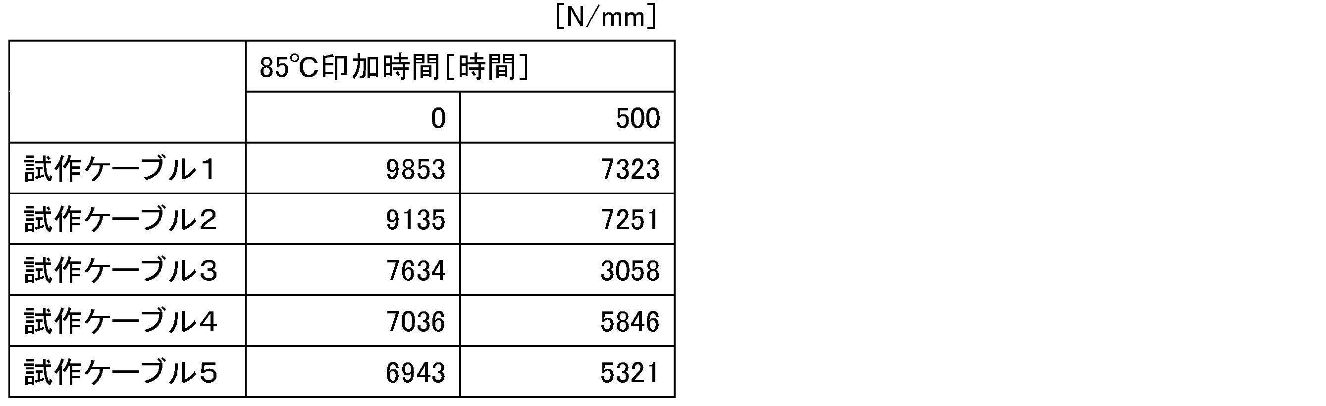
表2の結果から、試作ケーブル3のみが、他の試作ケーブルと比べ、500時間経過時の破断荷重が大幅に小さかった。さらに、本試作ケーブルの外被6Aを被覆した時の径は、最大風圧荷重(着氷時を含む)が3200N程度印加されることを前提に設計されているが、それをも下回った。そこで、この試作ケーブル3を不合格、残りの試作ケーブル1、2、4及び5を合格と評価した。
以上の表1、表2の結果から、合格した試作ケーブル1、2、4及び5における、最小の密着力は、252N/10mm(表1、試作ケーブル5の500時間経過時の密着力)であることがわかる。また、外被6Aと支持線5との密着力は、支持線5の表面積に依存することは明らかである。このことから、支持線5の径をDとした場合、必要な密着力F(N/mm)は、次の式で表すことができる。
[数1]
F ≧ D×π×1.77 (式1)
[数1]
F ≧ D×π×1.77 (式1)
===その他の実施形態===
上述の実施形態は、本発明の理解を容易にするためのものであり、本発明を限定して解釈するためのものではない。本発明は、その趣旨を逸脱することなく、変更・改良され得ると共に、本発明には、その等価物が含まれることは言うまでもない。
上述の実施形態は、本発明の理解を容易にするためのものであり、本発明を限定して解釈するためのものではない。本発明は、その趣旨を逸脱することなく、変更・改良され得ると共に、本発明には、その等価物が含まれることは言うまでもない。
1 光ファイバケーブル、2 支持線部、3・3A 本体部、
4 首部、5 支持線、6A・6B 外被、7 抗張力体、
8 セパレータ、9 光ファイバ、10 ノッチ、
11 把持部、12 把持用グリップ、13 固定用部材、
14 カバー、15 固定具、16 素線、
17A・17B 分岐クロージャ、18 引込用支持線、
19 端部把持用グリップ、20 引込孔、21 試験機構、
22 穴付固定板 23 ロードセル
4 首部、5 支持線、6A・6B 外被、7 抗張力体、
8 セパレータ、9 光ファイバ、10 ノッチ、
11 把持部、12 把持用グリップ、13 固定用部材、
14 カバー、15 固定具、16 素線、
17A・17B 分岐クロージャ、18 引込用支持線、
19 端部把持用グリップ、20 引込孔、21 試験機構、
22 穴付固定板 23 ロードセル
Claims (9)
- 光ファイバを含む本体部と、支持線部とからなる光ファイバケーブルを、把持用部材を用いて把持する方法であって、
前記支持線部は、金属以外の材料からなる支持線と、前記支持線を被覆する外被を含み、
前記外被が前記支持線を被覆したまま、前記把持用部材を前記支持線部に対して締め付けて把持すること
を特徴とする光ファイバケーブルの把持方法。 - 前記把持用部材を前記支持線部に対して螺旋状に巻き付けるようにして締め付けることを特徴とする請求項1記載の光ファイバケーブルの把持方法。
- 前記支持線はガラス繊維強化プラスチックからなることを特徴とする請求項1記載の光ファイバケーブルの把持方法。
- 前記把持用部材と前記外被との間に摩擦材料を含むことを特徴とする請求項1記載の光ファイバケーブルの把持方法。
- 前記外被の押し潰しが発生しない程度に前記把持用部材が前記支持線部に対して締め付けて把持することを特徴とする請求項1記載の光ファイバケーブルの把持方法。
- 前記外被が前記本体部と前記支持線とを一体的に被覆することで、前記本体部と前記支持線とを連結する首部を間欠的に形成していること
を特徴とする請求項1記載の光ファイバケーブルの把持方法。 - 前記本体部と前記支持線部とを連結していない分離部において前記支持線部を固定構造物に把持すること
を特徴とする請求項5記載の光ファイバケーブルの把持方法。 - 前記本体部は、前記支持線部に対して弛んでいることを特徴とする請求項6記載の光ファイバケーブルの把持方法。
- 前記支持線の径をDとしたときに、
前記外被と前記支持線との密着力Fが1.77πD[N/mm]以上である請求項1記載の光ファイバケーブルの把持方法。
Priority Applications (2)
| Application Number | Priority Date | Filing Date | Title |
|---|---|---|---|
| EP17814926.6A EP3451037A4 (en) | 2016-06-23 | 2017-02-15 | METHOD FOR GRAPPING A FIBERGLASS CABLE AND FIBERGLASS CABLE GRIP TOOL |
| CN201780031207.7A CN109154707A (zh) | 2016-06-23 | 2017-02-15 | 光纤缆线的把持方法以及光纤缆线的把持工具 |
Applications Claiming Priority (2)
| Application Number | Priority Date | Filing Date | Title |
|---|---|---|---|
| JP2016124561A JP2017227791A (ja) | 2016-06-23 | 2016-06-23 | 光ファイバケーブルの把持方法、光ファイバケーブル及び把持用部材付き光ファイバケーブル |
| JP2016-124561 | 2016-06-23 |
Publications (1)
| Publication Number | Publication Date |
|---|---|
| WO2017221454A1 true WO2017221454A1 (ja) | 2017-12-28 |
Family
ID=60783971
Family Applications (1)
| Application Number | Title | Priority Date | Filing Date |
|---|---|---|---|
| PCT/JP2017/005505 Ceased WO2017221454A1 (ja) | 2016-06-23 | 2017-02-15 | 光ファイバケーブルの把持方法及び光ファイバケーブル把持具 |
Country Status (5)
| Country | Link |
|---|---|
| EP (1) | EP3451037A4 (ja) |
| JP (1) | JP2017227791A (ja) |
| CN (1) | CN109154707A (ja) |
| TW (1) | TWI641886B (ja) |
| WO (1) | WO2017221454A1 (ja) |
Families Citing this family (2)
| Publication number | Priority date | Publication date | Assignee | Title |
|---|---|---|---|---|
| JP7279520B2 (ja) | 2019-05-30 | 2023-05-23 | 株式会社オートネットワーク技術研究所 | 配線部材 |
| US11886029B2 (en) | 2021-03-10 | 2024-01-30 | Afl Telecommunications Llc | Systems and methods of managing cables in telecommunication systems |
Citations (8)
| Publication number | Priority date | Publication date | Assignee | Title |
|---|---|---|---|---|
| JPS5995304U (ja) * | 1982-12-18 | 1984-06-28 | 東北電力株式会社 | ノンメタリツク自己支持型架空光ケ−ブル |
| US5043037A (en) * | 1989-11-22 | 1991-08-27 | Sumitomo Electric Fiber Optics Corporation | Method for making high strain aerial fiber optic cable |
| JPH04132720U (ja) * | 1991-02-08 | 1992-12-09 | 日本大洋海底電線株式会社 | 自己支持型開放同軸ケーブル |
| JPH08265941A (ja) * | 1995-03-20 | 1996-10-11 | P L P:Kk | Sz撚り巻付けグリップおよびその製造方法 |
| JP2001328189A (ja) * | 2000-05-23 | 2001-11-27 | Ube Nitto Kasei Co Ltd | 繊維強化合成樹脂製線状物 |
| JP2003029110A (ja) * | 2001-07-19 | 2003-01-29 | Fujikura Ltd | 自己支持型架空光ケーブルおよびその端末引留め構造 |
| JP2003090943A (ja) * | 2001-09-19 | 2003-03-28 | Fujikura Ltd | 光ファイバケーブル及び光ファイバケーブルの引き留め方法 |
| JP2007148121A (ja) * | 2005-11-29 | 2007-06-14 | Sumitomo Denko Steel Wire Kk | 光ファイバケーブル保持具、光ファイバケーブル引き留め構造及び光ファイバケーブル引き留め方法 |
Family Cites Families (7)
| Publication number | Priority date | Publication date | Assignee | Title |
|---|---|---|---|---|
| US4852965A (en) * | 1987-02-27 | 1989-08-01 | American Telephone And Telegraph Company At&T Bell Laboratories | Composite service and distribution communications media |
| US6356690B1 (en) * | 1999-10-20 | 2002-03-12 | Corning Cable Systems Llc | Self-supporting fiber optic cable |
| US6728455B2 (en) * | 2001-09-04 | 2004-04-27 | Fujikura Ltd. | Optical fiber drop cable and manufacturing method thereof |
| JP2004309648A (ja) * | 2003-04-03 | 2004-11-04 | Sumitomo Electric Ind Ltd | 光ファイバケーブルの製造方法 |
| TWI252939B (en) * | 2004-05-31 | 2006-04-11 | Kaiphone Comm Co Ltd | Optical fiber patch cord |
| US7218821B2 (en) * | 2004-08-20 | 2007-05-15 | Furukawa Electric North America Inc. | Optical fiber cables |
| US8203074B2 (en) * | 2006-10-25 | 2012-06-19 | Advanced Technology Holdings Ltd. | Messenger supported overhead cable for electrical transmission |
-
2016
- 2016-06-23 JP JP2016124561A patent/JP2017227791A/ja active Pending
-
2017
- 2017-02-15 WO PCT/JP2017/005505 patent/WO2017221454A1/ja not_active Ceased
- 2017-02-15 CN CN201780031207.7A patent/CN109154707A/zh active Pending
- 2017-02-15 EP EP17814926.6A patent/EP3451037A4/en not_active Withdrawn
- 2017-03-01 TW TW106106678A patent/TWI641886B/zh not_active IP Right Cessation
Patent Citations (8)
| Publication number | Priority date | Publication date | Assignee | Title |
|---|---|---|---|---|
| JPS5995304U (ja) * | 1982-12-18 | 1984-06-28 | 東北電力株式会社 | ノンメタリツク自己支持型架空光ケ−ブル |
| US5043037A (en) * | 1989-11-22 | 1991-08-27 | Sumitomo Electric Fiber Optics Corporation | Method for making high strain aerial fiber optic cable |
| JPH04132720U (ja) * | 1991-02-08 | 1992-12-09 | 日本大洋海底電線株式会社 | 自己支持型開放同軸ケーブル |
| JPH08265941A (ja) * | 1995-03-20 | 1996-10-11 | P L P:Kk | Sz撚り巻付けグリップおよびその製造方法 |
| JP2001328189A (ja) * | 2000-05-23 | 2001-11-27 | Ube Nitto Kasei Co Ltd | 繊維強化合成樹脂製線状物 |
| JP2003029110A (ja) * | 2001-07-19 | 2003-01-29 | Fujikura Ltd | 自己支持型架空光ケーブルおよびその端末引留め構造 |
| JP2003090943A (ja) * | 2001-09-19 | 2003-03-28 | Fujikura Ltd | 光ファイバケーブル及び光ファイバケーブルの引き留め方法 |
| JP2007148121A (ja) * | 2005-11-29 | 2007-06-14 | Sumitomo Denko Steel Wire Kk | 光ファイバケーブル保持具、光ファイバケーブル引き留め構造及び光ファイバケーブル引き留め方法 |
Non-Patent Citations (1)
| Title |
|---|
| See also references of EP3451037A4 * |
Also Published As
| Publication number | Publication date |
|---|---|
| TWI641886B (zh) | 2018-11-21 |
| EP3451037A1 (en) | 2019-03-06 |
| CN109154707A (zh) | 2019-01-04 |
| EP3451037A4 (en) | 2019-12-18 |
| TW201800792A (zh) | 2018-01-01 |
| JP2017227791A (ja) | 2017-12-28 |
Similar Documents
| Publication | Publication Date | Title |
|---|---|---|
| TWI537624B (zh) | Fiber optic cable | |
| EP3605174B1 (en) | Optical fiber cable | |
| TW205598B (ja) | ||
| RU166005U1 (ru) | Пленочный связующий материал для волоконно-оптического кабеля | |
| US8798418B2 (en) | Optical cable with improved strippability | |
| CN101706604A (zh) | 一种易分支的光缆 | |
| WO2017221454A1 (ja) | 光ファイバケーブルの把持方法及び光ファイバケーブル把持具 | |
| US6775445B2 (en) | Optical fiber drop cable | |
| CN113678045A (zh) | 一种架空光缆敷设金具及可使用该金具敷设的架空光缆 | |
| JP5546412B2 (ja) | 光ケーブル | |
| CN211208018U (zh) | 一种布线用柔软光电混合缆 | |
| CN211554402U (zh) | 一种三单元层绞式轻型光缆 | |
| JP6298479B2 (ja) | 光ファイバケーブル | |
| JP4665048B1 (ja) | 光ドロップケーブル | |
| JPH10148737A (ja) | 架空屋外用光ケーブル | |
| CN211905794U (zh) | 一种高密度易剥离防鼠型微束多芯光缆 | |
| CN209784617U (zh) | 一种拉远光缆 | |
| CN211263889U (zh) | 一种架空光缆及该光缆敷设金具 | |
| CN211578458U (zh) | 一种超轻型光电复合电缆 | |
| CN210572932U (zh) | 一种自承式复合光缆 | |
| JPH10148738A (ja) | 架空集合屋外用光ケーブルおよびその製造方法 | |
| JP5638895B2 (ja) | 光ファイバケーブル | |
| CN220820329U (zh) | 耐弯曲的光纤结构 | |
| CN203287582U (zh) | 纤维补强合成树脂制抗张力线状物及使用了其的引入线光缆 | |
| JP2004252003A (ja) | 光ファイバケーブル |
Legal Events
| Date | Code | Title | Description |
|---|---|---|---|
| 121 | Ep: the epo has been informed by wipo that ep was designated in this application |
Ref document number: 17814926 Country of ref document: EP Kind code of ref document: A1 |
|
| ENP | Entry into the national phase |
Ref document number: 2017814926 Country of ref document: EP Effective date: 20181129 |
|
| NENP | Non-entry into the national phase |
Ref country code: DE |