WO2017221702A1 - Moteur et dispositif de pompe - Google Patents
Moteur et dispositif de pompe Download PDFInfo
- Publication number
- WO2017221702A1 WO2017221702A1 PCT/JP2017/021097 JP2017021097W WO2017221702A1 WO 2017221702 A1 WO2017221702 A1 WO 2017221702A1 JP 2017021097 W JP2017021097 W JP 2017021097W WO 2017221702 A1 WO2017221702 A1 WO 2017221702A1
- Authority
- WO
- WIPO (PCT)
- Prior art keywords
- radial direction
- positioning
- rotor
- circuit board
- stator
- Prior art date
- Legal status (The legal status is an assumption and is not a legal conclusion. Google has not performed a legal analysis and makes no representation as to the accuracy of the status listed.)
- Ceased
Links
Images


Classifications
-
- H—ELECTRICITY
- H02—GENERATION; CONVERSION OR DISTRIBUTION OF ELECTRIC POWER
- H02K—DYNAMO-ELECTRIC MACHINES
- H02K5/00—Casings; Enclosures; Supports
- H02K5/04—Casings or enclosures characterised by the shape, form or construction thereof
- H02K5/22—Auxiliary parts of casings not covered by groups H02K5/06-H02K5/20, e.g. shaped to form connection boxes or terminal boxes
- H02K5/225—Terminal boxes or connection arrangements
-
- H—ELECTRICITY
- H02—GENERATION; CONVERSION OR DISTRIBUTION OF ELECTRIC POWER
- H02K—DYNAMO-ELECTRIC MACHINES
- H02K7/00—Arrangements for handling mechanical energy structurally associated with dynamo-electric machines, e.g. structural association with mechanical driving motors or auxiliary dynamo-electric machines
- H02K7/14—Structural association with mechanical loads, e.g. with hand-held machine tools or fans
-
- F—MECHANICAL ENGINEERING; LIGHTING; HEATING; WEAPONS; BLASTING
- F04—POSITIVE - DISPLACEMENT MACHINES FOR LIQUIDS; PUMPS FOR LIQUIDS OR ELASTIC FLUIDS
- F04D—NON-POSITIVE-DISPLACEMENT PUMPS
- F04D13/00—Pumping installations or systems
- F04D13/02—Units comprising pumps and their driving means
- F04D13/06—Units comprising pumps and their driving means the pump being electrically driven
-
- F—MECHANICAL ENGINEERING; LIGHTING; HEATING; WEAPONS; BLASTING
- F04—POSITIVE - DISPLACEMENT MACHINES FOR LIQUIDS; PUMPS FOR LIQUIDS OR ELASTIC FLUIDS
- F04D—NON-POSITIVE-DISPLACEMENT PUMPS
- F04D29/00—Details, component parts, or accessories
- F04D29/60—Mounting; Assembling; Disassembling
-
- H—ELECTRICITY
- H02—GENERATION; CONVERSION OR DISTRIBUTION OF ELECTRIC POWER
- H02K—DYNAMO-ELECTRIC MACHINES
- H02K1/00—Details of the magnetic circuit
- H02K1/04—Details of the magnetic circuit characterised by the material used for insulating the magnetic circuit or parts thereof
-
- H—ELECTRICITY
- H02—GENERATION; CONVERSION OR DISTRIBUTION OF ELECTRIC POWER
- H02K—DYNAMO-ELECTRIC MACHINES
- H02K11/00—Structural association of dynamo-electric machines with electric components or with devices for shielding, monitoring or protection
- H02K11/20—Structural association of dynamo-electric machines with electric components or with devices for shielding, monitoring or protection for measuring, monitoring, testing, protecting or switching
- H02K11/21—Devices for sensing speed or position, or actuated thereby
- H02K11/215—Magnetic effect devices, e.g. Hall-effect or magneto-resistive elements
-
- H—ELECTRICITY
- H02—GENERATION; CONVERSION OR DISTRIBUTION OF ELECTRIC POWER
- H02K—DYNAMO-ELECTRIC MACHINES
- H02K29/00—Motors or generators having non-mechanical commutating devices, e.g. discharge tubes or semiconductor devices
- H02K29/06—Motors or generators having non-mechanical commutating devices, e.g. discharge tubes or semiconductor devices with position sensing devices
- H02K29/08—Motors or generators having non-mechanical commutating devices, e.g. discharge tubes or semiconductor devices with position sensing devices using magnetic effect devices, e.g. Hall-plates, magneto-resistors
-
- H—ELECTRICITY
- H02—GENERATION; CONVERSION OR DISTRIBUTION OF ELECTRIC POWER
- H02K—DYNAMO-ELECTRIC MACHINES
- H02K3/00—Details of windings
- H02K3/46—Fastening of windings on the stator or rotor structure
- H02K3/52—Fastening salient pole windings or connections thereto
- H02K3/521—Fastening salient pole windings or connections thereto applicable to stators only
- H02K3/522—Fastening salient pole windings or connections thereto applicable to stators only for generally annular cores with salient poles
-
- H—ELECTRICITY
- H02—GENERATION; CONVERSION OR DISTRIBUTION OF ELECTRIC POWER
- H02K—DYNAMO-ELECTRIC MACHINES
- H02K2211/00—Specific aspects not provided for in the other groups of this subclass relating to measuring or protective devices or electric components
- H02K2211/03—Machines characterised by circuit boards, e.g. pcb
Definitions
- the present invention relates to a motor having a partition wall disposed between a rotor and a stator. Moreover, this invention relates to a pump apparatus provided with this motor.
- a pump device including a pump chamber in which an impeller and a rotor are disposed, and a stator and a circuit board that are disposed outside the pump chamber is known (for example, see Patent Document 1).
- a partition wall is disposed between the stator and the circuit board and the pump chamber so as to prevent fluid from flowing into the arrangement position of the stator and the circuit board.
- the rotor includes a driving magnet.
- the stator is formed in a substantially cylindrical shape, and includes a driving coil and a stator core around which the driving coil is wound via an insulating member.
- the stator core includes an annular ring portion and a plurality of salient pole portions that protrude from the ring portion to the inside in the radial direction of the rotor.
- the insulating member includes an inner insulating portion disposed on the inner side in the radial direction of the rotor, an outer insulating portion disposed on the outer side in the radial direction, and a connecting insulating portion that connects the inner insulating portion and the outer insulating portion. ing.
- the partition is formed in a bottomed cylindrical shape.
- the circuit board is formed in a flat plate shape, and is fixed to the bottom of the partition wall so that the axial direction of the stator coincides with the thickness direction of the circuit board.
- the circuit board is mounted with a magnetic sensor having a magnetic sensing portion disposed opposite to the outer peripheral surface of the driving magnet via a partition wall.
- the terminals of the magnetic sensor are mounted on the circuit board so that the magnetic sensitive part protrudes from the circuit board, and the magnetic sensitive part is disposed between the end faces of the inner insulating parts adjacent in the circumferential direction of the rotor.
- a three-phase brushless motor is constituted by a rotor and a stator.
- the magnetic sensor also functions to detect the rotational position of the rotor by detecting the magnetic poles on the outer peripheral surface of the driving magnet, and the current supplied to the driving coil is controlled based on the detection result of the magnetic sensor. Has been.
- the magnetic sensor of the magnetic sensor that detects the magnetic poles on the outer peripheral surface of the driving magnet is opposed to the outer peripheral surface of the driving magnet via the partition wall, The distance between the outer peripheral surface of the driving magnet and the magnetic sensing part is increased. Therefore, in this pump device, when the arrangement position of the magnetic sensing portion is shifted outward in the radial direction of the rotor and the distance between the outer circumferential surface of the driving magnet and the magnetic sensing portion is further increased, the outer circumference of the driving magnet is detected by the magnetic sensor. There is a risk that the magnetic pole of the surface cannot be detected properly.
- an object of the present invention is to provide a motor having a partition wall disposed between a rotor and a stator, and a magnetic sensing portion of a magnetic sensor disposed opposite to the outer peripheral surface of the rotor drive magnet via the partition wall,
- An object of the present invention is to provide a motor capable of increasing the relative positional accuracy in the radial direction with respect to a magnet.
- this invention is providing the pump apparatus provided with this motor.
- a motor of the present invention includes a rotor having a driving magnet, a stator having a driving coil and disposed on the outer peripheral side of the rotor, and an abbreviated structure disposed between the rotor and the stator.
- a partition member having a bottomed cylindrical partition wall, a circuit board fixed to the partition wall outside the partition wall in the axial direction of the rotor, and a magnetic sensing portion disposed opposite to the outer peripheral surface of the driving magnet via the partition wall
- the stator includes an insulating member and an insulating member, where a first direction is a direction in which the circuit board is disposed with respect to the partition wall in the axial direction, and a second direction is a direction opposite to the first direction.
- the insulating member includes an inner flange that forms an inner portion of the insulating member in the radial direction
- the partition wall includes a cylindrical cylindrical portion disposed between the rotor and the stator, and a first direction end of the cylindrical portion. And a disk-shaped bottom portion to which the circuit board is fixed, and an inclined surface that gradually decreases in outer diameter toward the first direction side is formed at the first direction end of the outer peripheral surface of the partition wall.
- the collar includes a positioning part that regulates the position of the magnetic sensing part in the radial direction.
- the circuit board is mounted with the terminals of the magnetic sensor so that the magnetic sensing part protrudes from the circuit board to the second direction side.
- the magnetic part is arranged between the cylindrical part and the positioning part in the radial direction.
- the partition wall includes a cylindrical cylindrical portion disposed between the rotor and the stator, and a disk-shaped bottom portion that blocks the first direction end of the cylindrical portion and fixes the circuit board.
- the terminals of the magnetic sensor are mounted on the circuit board so that the magnetic sensitive part of the magnetic sensor arranged to face the outer peripheral surface of the driving magnet via the partition wall protrudes in the second direction side.
- the inclined surface where an outer diameter becomes small gradually is formed in the 1st direction end of the outer peripheral surface of a partition as it goes to a 1st direction side.
- the inclined surface of the partition wall is used to prevent excessive bending of the terminals of the magnetic sensor. It is possible to smoothly guide the magnetic sensitive part to the outer peripheral side of the cylindrical part.
- the inner flange that forms the inner portion of the insulating member in the radial direction includes a positioning portion that regulates the position of the magnetically sensitive portion in the radial direction, and the magnetically sensitive portion is the cylindrical portion in the radial direction. And the positioning part. Therefore, in the present invention, it is possible to accurately position the magnetically sensitive portion guided to the outer peripheral side of the cylindrical portion using the inclined surface of the partition wall in the radial direction by the outer peripheral surface of the cylindrical portion and the positioning portion. . Therefore, according to the present invention, it is possible to increase the relative positional accuracy in the radial direction between the magnetic sensing portion of the magnetic sensor and the driving magnet, which are arranged to face the outer peripheral surface of the driving magnet via the partition wall.
- the width in the circumferential direction of the rotor on the inner surface of the positioning portion in the radial direction is preferably larger than the width of the magnetically sensitive portion in the circumferential direction. If comprised in this way, according to the characteristic etc. of a motor, it will become possible to shift the relative position of the circumferential direction of the magnetic sensing part with respect to a stator. Therefore, a common insulating member can be used for motors having different characteristics and the like, and the versatility of the insulating member can be improved.
- the inner side surface of the positioning portion in the radial direction is formed in a curved surface having an arc shape with the rotation center of the rotor as the center of curvature when viewed from the axial direction.
- a chamfered portion is formed at the radially inner end of the end surface on the first direction side of the positioning portion.
- the inner side surface of the positioning portion in the radial direction is an inclined surface that is inclined toward the inner side in the radial direction toward the second direction side. If comprised in this way, when fixing the circuit board with which the magnetic sensor was mounted from the 1st direction side to the bottom part of a partition, a magnetic sensitive part will enter easily between the cylindrical part and positioning part in radial direction.
- the inner flange portion is formed in a flat plate shape perpendicular to the radial direction, and the positioning portion includes a protruding portion protruding from the inner side surface of the inner flange portion in the radial direction.
- the positioning portion includes a protruding portion protruding from the inner side surface of the inner flange portion in the radial direction.
- the end surface on the first direction side of the protruding portion is arranged on the same plane as the end surface on the first direction side of the inner flange.
- a chamfered portion is formed at the radially inner end of the end surface on the second direction side of the magnetic sensitive portion. If comprised in this way, when fixing the circuit board with which the magnetic sensor was mounted from the 1st direction side to the bottom part of a partition, a magnetic sensitive part will enter easily between the cylindrical part and positioning part in radial direction.
- the terminal urges the magnetic sensitive portion radially inward, and the magnetic sensitive portion is in contact with the outer peripheral surface of the cylindrical portion.
- the positioning portion is formed with a depression that is recessed from the inner side surface of the inner flange in the radial direction.
- a positioning projection for positioning a circuit board fixed to the partition wall member is formed on the surface in the first direction at the bottom so as to protrude toward the first direction.
- the partition member includes a cylindrical outer cylinder portion disposed on the outer peripheral side of the partition wall, and a bottom surface portion connecting the lower end of the cylindrical portion and the lower end of the outer cylinder portion. It is preferable that a columnar protrusion rising upward is formed, and a circuit board positioning portion for positioning the circuit board is formed on the tip end side of the protrusion together with the positioning protrusion.
- the stator core includes three salient pole portions, the three salient pole portions are formed at an equiangular pitch, are arranged at regular intervals in the circumferential direction, and the stator has three salient poles.
- Three driving members each having three insulating members attached to each of the pole portions and wound around three salient pole portions via the three insulating members
- the insulating member includes three inner flanges, one on each insulating member, and three inner flanges have three inner flanges, one on each inner flange. It is preferable that a positioning unit is provided, and that the three positioning units are each provided with three magnetic sensors, one on each positioning unit.
- the motor of the present invention is a pump device including an impeller attached to a rotor, and is used for a pump device in which a part of a pump chamber in which an impeller is disposed and a fluid passes is defined by a partition member. Can do.
- this pump device it is possible to increase the relative positional accuracy in the radial direction between the magnetic sensing part of the magnetic sensor and the driving magnet that are arranged to face the outer peripheral surface of the driving magnet via a partition wall.
- FIG. 2 is a perspective view of a stator, a partition member, and a magnetic sensor shown in FIG. 1. It is a perspective view of the magnetic sensor and insulator shown in FIG. It is a figure for demonstrating the fixing method of the circuit board to the partition shown in FIG. It is a perspective view for demonstrating the structure of the positioning part concerning other embodiment of this invention. It is sectional drawing for demonstrating the structure of the positioning part concerning other embodiment of this invention.
- FIG. 1 is a cross-sectional view of a pump device 1 according to an embodiment of the present invention.
- FIG. 2 is a perspective view of the stator 5, the partition member 11, and the magnetic sensor 7 shown in FIG.
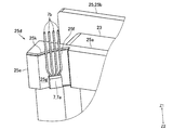
- FIG. 3 is a perspective view of the magnetic sensor 7 and the insulator 25 shown in FIG.
- the upper side (Z1 direction side) in FIG. 1 is the “upper” side
- the lower side (Z2 direction side) in FIG. 1 is the “lower” side.
- the pump device 1 of this embodiment is a type of pump called a can pump (canned motor pump), and includes an impeller 2 and a motor 3 that rotates the impeller 2.
- the motor 3 is a three-phase DC brushless motor.
- the motor 3 includes a rotor 4, a stator 5, a circuit board 6 for controlling the motor 3, and a magnetic sensor 7 for detecting the rotational position of the rotor 4.
- the impeller 2, the rotor 4, the stator 5, the circuit board 6, and the magnetic sensor 7 are arranged inside a case body that includes a housing 8 that constitutes a part of the motor 3 and a case 9 that covers the lower portion of the housing 8. Has been.
- the housing 8 and the case 9 are fixed to each other by screws not shown.
- the case 9 is formed with a fluid suction portion 9a and a fluid discharge portion 9b. Inside the case 9 is formed a pump chamber 10 through which the fluid sucked from the suction portion 9a passes toward the discharge portion 9b.
- the housing 8 includes a partition member 11 having a partition wall 11 a disposed between the rotor 4 and the stator 5 so as to separate the rotor 4 and the stator 5, and a cover 12 fixed to the upper end side of the partition member 11. ing.
- the rotor 4 includes a rotating shaft 14 and a driving magnet 15.
- the rotating shaft 14 is disposed so that the axial direction of the rotating shaft 14 coincides with the vertical direction. That is, the vertical direction is the axial direction of the rotor 4.
- the drive magnet 15 is formed in a cylindrical shape.
- the driving magnet 15 is fixed to the outer peripheral surface of the rotating shaft 14 via a magnet holding member 16.
- N and S poles are alternately magnetized in the circumferential direction of the drive magnet 15. In this embodiment, two magnetic poles, one N pole and one S pole, are magnetized on the outer peripheral surface of the driving magnet 15.
- the impeller 2 is fixed to the lower end of the rotating shaft 14. That is, the impeller 2 is attached to the rotor 4.
- the impeller 2 is disposed inside the pump chamber 10.
- the upper end side of the rotating shaft 14 is rotatably held by the bearing 17.
- the bearing 17 is fixed to the upper end side of the partition wall 11a.
- the lower end side of the rotating shaft 14 is rotatably held by the bearing 18.
- the bearing 18 is held by a bearing holding member 19 fixed to the lower end side of the partition wall 11a. Between the bearing 18 and the bearing holding member 19, a rubber seal member 20 that prevents fluid from flowing into the place where the drive magnet 15 is disposed is disposed.
- the stator 5 includes a driving coil 23, a stator core 24, and an insulator 25 as an insulating member, and is formed in a cylindrical shape as a whole.
- the stator 5 is disposed on the outer peripheral side of the rotor 4 via the partition wall 11a.
- the stator 5 is arrange
- the radial direction of the rotor 4 and the stator 5 is referred to as “radial direction”, and the circumferential direction (circumferential direction) of the rotor 4 and the stator 5 is referred to as “circumferential direction”.
- the partition wall member 11 includes the partition wall 11a.
- the partition wall 11a is formed in a substantially bottomed cylindrical shape, and includes a cylindrical portion 11b and a bottom portion 11c.
- the cylindrical portion 11b is formed in a cylindrical shape.
- the cylindrical portion 11 b is disposed so as to cover the outer peripheral surface of the driving magnet 15, and is disposed between the rotor 4 and the stator 5 in the radial direction.
- the bottom part 11c is formed in a disk shape that closes the upper end of the cylindrical part 11b.
- the bearing 17 is fixed to the lower surface of the bottom portion 11c, and the bearing holding member 19 is fixed to the lower end side of the inner peripheral surface of the cylindrical portion 11b.
- a positioning projection 11d for positioning the circuit board 6 fixed to the partition wall member 11 is formed on the upper surface of the bottom portion 11c so as to protrude upward.
- two positioning protrusions 11d are formed on the bottom surface 11c.
- An inclined surface 11e is formed at the upper end of the outer peripheral surface of the partition wall 11a so that the outer diameter gradually decreases toward the upper side. That is, a tapered inclined surface 11e is formed at the upper end of the outer peripheral surface of the partition wall 11a, and the upper end side portion of the partition wall 11a has a truncated cone shape.
- the partition member 11 includes a cylindrical outer cylinder portion 11f disposed on the outer peripheral side of the partition wall 11a, and a bottom surface portion 11g that connects the lower end of the cylindrical portion 11b and the lower end of the outer cylinder portion 11f.
- the outer cylinder part 11f is formed in a substantially cylindrical shape, for example.
- the height of the outer cylinder portion 11f (the height in the vertical direction) is higher than the height of the partition wall 11a.
- the stator 5 is disposed between the cylindrical portion 11b and the outer cylindrical portion 11f in the radial direction.
- the bottom surface portion 11g is formed in an annular shape.
- the lower side of the bottom surface portion 11g is a pump chamber 10, and a part of the pump chamber 10 is defined by the bottom surface portion 11g. That is, a part of the pump chamber 10 is defined by the partition member 11.
- the bottom surface portion 11g functions to prevent the fluid in the pump chamber 10 from flowing into the locations where the stator 5 and the circuit board 6 are disposed.
- a cylindrical projection 11h rising upward is formed on the bottom surface portion 11g (see FIG. 2), and the circuit board 6 is positioned together with the positioning projection 11d on the tip end side (upper end portion) of the projection 11h.
- a positioning part is formed. That is, the tip of the protrusion 11h is a circuit board positioning portion. In FIG. 1, the protrusion 11h is not shown.
- the circuit board 6 is a rigid board such as a glass epoxy board, and is formed in a flat plate shape.
- the circuit board 6 is disposed above the drive coil 23, the stator core 24, and the insulator 25 so that the thickness direction of the circuit board 6 coincides with the vertical direction.
- the circuit board 6 is disposed below the upper end of the outer cylinder portion 11f. Further, the circuit board 6 is fixed to the bottom portion 11c in a state where the circuit board 6 is positioned by the positioning protrusions 11d and the like. That is, the circuit board 6 is fixed to the partition wall 11a above the bottom portion 11c (that is, outside the partition wall 11a in the vertical direction).
- the upward direction (Z1 direction) of this embodiment is a first direction in which the circuit board 6 is disposed with respect to the partition wall 11a in the axial direction of the rotor 4, and the downward direction (Z2 direction) is The second direction is opposite to the first direction.
- the magnetic sensor 7 is a Hall element.
- the magnetic sensor 7 functions to detect the rotational position of the rotor 4 by detecting the magnetic poles on the outer peripheral surface of the driving magnet 15.
- the motor 3 is a three-phase DC brushless motor, and the motor 3 includes three magnetic sensors 7.
- the magnetic sensor 7 includes a magnetic sensing part 7a formed in a substantially rectangular parallelepiped shape and a plurality of terminals (leads) 7b extending from the magnetic sensing part 7a.
- the magnetic sensor 7 is mounted on the circuit board 6. Specifically, the terminal 7 b is mounted on the circuit board 6 so that the magnetic sensitive part 7 a protrudes downward from the circuit board 6.
- the three magnetic sensors 7 are mounted on the circuit board 6 so that the three magnetic sensors 7 are arranged at a 120 ° pitch with respect to the rotation center of the rotor 4 when viewed from the vertical direction.
- the magnetic sensor 7 may be other than a Hall element.
- the magnetic sensing part 7a is disposed opposite to the outer peripheral surface of the driving magnet 15 via the partition wall 11a. Specifically, the magnetic sensitive surface of the magnetic sensitive portion 7a is disposed opposite to the outer peripheral surface of the driving magnet 15 via the cylindrical portion 11b. Moreover, the magnetic sensitive part 7a is the upper end side part of the cylindrical part 11b, and is arrange
- the cover 12 is formed in a flat, substantially bottomed cylindrical shape.
- the cover 12 is fixed to the upper end side of the inner peripheral surface of the outer cylinder portion 11 f and closes the opening at the upper end of the cover 12. That is, the cover 12 covers the stator 5 and the circuit board 6 from above, and the stator 5 and the circuit board 6 are in a space defined by the cylindrical portion 11b, the outer cylindrical portion 11f, the bottom surface portion 11g, and the cover 12.
- the resin sealing member may be filled in the space defined by the cylindrical portion 11b, the outer cylindrical portion 11f, the bottom surface portion 11g, and the cover 12.
- the stator 5 includes the drive coil 23, the stator core 24, and the insulator 25.
- the stator 5 also includes terminal pins (not shown) to which the end portions of the drive coils 23 are electrically connected.
- the lower end side of the terminal pin is fixed to an insulator 25, and the upper end side of the terminal pin is fixed to the circuit board 6 by soldering.
- the stator core 24 is a laminated core formed by laminating thin magnetic plates made of a magnetic material.
- the stator core 24 includes an outer peripheral ring portion 24a formed in an annular shape and a plurality of salient pole portions 24b protruding from the outer peripheral ring portion 24a toward the inner side in the radial direction.
- the stator core 24 of this embodiment includes three salient pole portions 24b.
- the three salient pole portions 24b are formed at an equiangular pitch, and are arranged at regular intervals in the circumferential direction.
- the tip portion of the salient pole portion 24b is formed in a curved surface shape that has an arc shape with the rotation center of the rotor 4 as the center of curvature when viewed from above and below.
- the insulator 25 is made of an insulating resin material.
- the insulator 25 is attached to each salient pole portion 24 b, and the stator 5 includes three insulators 25.
- the insulator 25 is formed in a cylindrical shape with a flange having flanges at both ends, and the salient pole portion 24b so that the axial direction of the insulator 25 formed in a cylindrical shape matches the radial direction of the stator 5. Is attached.
- the insulator 25 includes an inner flange portion 25a that constitutes an inner portion of the insulator 25 in the radial direction, an outer flange portion 25b that constitutes an outer portion of the insulator 25 in the radial direction, an inner flange portion 25a, and an outer flange portion 25b. It is comprised from the cylinder part 25c (refer FIG. 3) which connects.
- the cylinder part 25c is formed in a square cylinder shape.
- a driving coil 23 is wound around the cylindrical portion 25c. That is, the drive coil 23 is wound around the salient pole portion 24 b via the insulator 25. Switching of energization to the driving coil 23 wound around the three salient pole portions 24 b is performed based on the detection result of the magnetic sensor 7.
- the inner flange portion 25a and the outer flange portion 25b are formed in a flat plate shape orthogonal to the radial direction and are formed in a square ring shape.
- the inner flange portion 25a covers the tip end portion of the salient pole portion 24b having a circular arc shape when viewed from the vertical direction from the outer side in the radial direction.
- the outer flange portion 25b covers a part of the outer peripheral ring portion 24a from the inner side in the radial direction.
- the inner flange portion 25a and the outer flange portion 25b function to prevent the driving coil 23 wound around the cylindrical portion 25c from being collapsed.
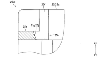
- the inner flange portion 25a includes a positioning portion 25d that regulates the position of the magnetic sensing portion 7a in the radial direction. As shown in FIG. 3, the positioning portion 25d is disposed on the upper end side of the inner flange portion 25a. Moreover, the positioning part 25d is arrange
- the positioning portion 25d includes a protruding portion 25e that protrudes from the inner surface of the inner flange portion 25a in the radial direction.
- the positioning portion 25d is formed with a hollow portion 25f that is recessed from the inner side surface of the inner flange portion 25a in the radial direction.
- the part in the circumferential direction of the positioning part 25d which controls the position of the magnetic sensing part 7a can be enlarged because the hollow part 25f is formed.
- the protruding portion 25e is formed so that the shape when viewed from above and below is substantially trapezoidal.
- One end surface of the protruding portion 25e in the circumferential direction is arranged on the same plane as one end surface of the inner flange portion 25a in the circumferential direction.
- the upper end surface of the protrusion 25e is disposed below the upper end surface of the inner flange 25a.
- the lower end surface of the protruding portion 25e is disposed on the same plane as the upper surface of the inner peripheral surface of the cylindrical portion 25c.
- the hollow portion 25f is formed so that the shape when viewed from the up-down direction is a substantially triangular shape.
- the recessed portion 25f is formed between the upper end surface of the inner flange portion 25a and the lower end surface of the protruding portion 25e in the vertical direction.
- the inner side surface 25g of the positioning portion 25d in the radial direction is composed of the inner side surface of the protruding portion 25e in the radial direction and the inner side surface of the recessed portion 25f in the radial direction.
- the inner side surface 25g is formed in a curved surface shape. Specifically, the inner side surface 25g is formed in a curved surface having an arc shape whose center of curvature is the rotation center of the rotor 4 when viewed from the vertical direction.
- the inner side surface 25g is a vertical surface that is not inclined with respect to the vertical direction.
- the width of the inner side surface 25g in the circumferential direction is wider than the width of the magnetically sensitive portion 7a in the circumferential direction.
- the range in which the protruding portion 25e is formed in the vertical direction of the positioning portion 25d is defined as the lower end side positioning portion 25h, and the inner side surface of the lower end positioning portion 25h in the radial direction (that is, the protruding portion 25e in the radial direction).
- the width of the lower end side inner side surface 25j in the circumferential direction is The width is wider than the width of the magnetically sensitive portion 7a in the circumferential direction.
- a chamfered portion 25k is formed at the radially inner end of the upper end surface of the positioning portion 25d. That is, a chamfered portion 25k is formed at the radially inner end of the upper end surface of the protrusion 25e and the radially inner end of the upper end surface of the portion of the positioning portion 25d where the recess 25f is formed.
- the radially inner end of the upper end surface of the positioning portion 25d is an inclined surface that is inclined so as to be directed radially outward as it goes upward.
- a chamfered portion is also formed on a portion other than the radially inner end of the upper end surface of the positioning portion 25d.
- the magnetic sensing portion 7a is disposed opposite to the outer peripheral surface of the driving magnet 15 via the partition wall 11a. Specifically, the magnetic sensitive part 7a is disposed between the cylindrical part 11b and the positioning part 25d in the radial direction. More specifically, the magnetic sensing portion 7a is disposed between the outer peripheral surface of the portion on the upper end side of the cylindrical portion 11b and below the inclined surface 11e and the lower end side inner surface 25j in the radial direction. . Moreover, the magnetic sensitive part 7a is mounted on the upper surface of the tip part of the salient pole part 24b.
- FIG. 4 is a view for explaining a method of fixing the circuit board 6 to the partition wall 11a shown in FIG.
- the circuit board 6 on which the magnetic sensor 7 is mounted is fixed to the partition wall 11a of the partition wall member 11 on which the stator 5 is mounted.
- the lower end side (the magnetic sensitive part 7a side) of the magnetic sensor 7 is mounted on the upper end side (the circuit board 6) as shown in FIG.
- the terminal 7b is slightly bent inward in the radial direction so as to be disposed radially inward from the upper end side of the terminal 7b.
- the circuit board 6 is lowered from above the partition wall member 11 with the stator 5 attached until the circuit board 6 is positioned by the positioning protrusions 11d and 11h.
- the circuit board 6 is lowered, as shown by a solid line in FIG. 4B, the radially inner portion of the lower end surface of the magnetic sensing portion 7a comes into contact with the inclined surface 11e of the partition wall 11a, and the magnetic sensing portion 7a.
- the terminal 7b is elastically deformed so as to move outward in the radial direction.
- the terminal 7b is elastically deformed outward in the radial direction until the lower end of the magnetic sensing portion 7a reaches the lower portion of the inclined surface 11e on the outer peripheral side of the cylindrical portion 11b (see the two-dot chain line in FIG. 4B). .
- the magnetic sensing portion 7a is urged radially inward by a terminal 7b that is elastically deformed, and contacts the outer peripheral surface of the cylindrical portion 11b. That is, the magnetic sensitive part 7a is arranged without a gap with respect to the outer peripheral surface of the cylindrical part 11b. That is, the terminal 7b urges the magnetic sensing part 7a inward in the radial direction, and the magnetic sensing part 7a is in contact with the outer peripheral surface of the cylindrical part 11b. Since the magnetic sensing portion 7a of the magnetic sensor 7 is in contact with the outer peripheral surface of the cylindrical portion 11b, the distance from the driving magnet can be reduced, and the magnetic pole on the outer peripheral surface of the driving magnet can be detected appropriately. can do.
- the magnetically sensitive portion 7a When the circuit board 6 is lowered until it is positioned by the positioning protrusions 11d and 11h, the magnetically sensitive portion 7a has a cylindrical portion 11b and a lower end side inner peripheral surface 25j in the radial direction, as indicated by a broken line in FIG. Between. In this state, the tip portions of the positioning projections 11d and the projections 11h are crushed while being heated, and the circuit board 6 is welded and fixed to the partition walls 11a. Alternatively, the circuit board 6 is fixed to the partition wall 11a with screws or the like not shown.
- the tapered inclined surface 11e is formed at the upper end of the outer peripheral surface of the partition wall 11a, and the circuit board 6 on which the magnetic sensor 7 is mounted is fixed to the partition wall 11a from above.
- the magnetic sensing portion 7a of the magnetic sensor 7 contacts the inclined surface 11e and is guided along the inclined surface 11e to the lower portion of the inclined surface 11e on the outer peripheral side of the cylindrical portion 11b. Therefore, in this embodiment, when the circuit board 6 on which the magnetic sensor 7 is mounted is fixed to the partition wall 11a from the upper side, the magnetic sensor 7 cannot be seen from the upper side, but the magnetic sensor 7 is utilized by using the inclined surface 11e. It is possible to smoothly guide the magnetic sensing portion 7a to the outer peripheral side of the cylindrical portion 11b while preventing excessive bending of the terminal 7b.
- the inner flange portion 25a of the insulator 25 is provided with a positioning portion 25d that regulates the position of the magnetic sensing portion 7a in the radial direction.
- the magnetic sensing portion 7a is positioned with the cylindrical portion 11b in the radial direction. It is arrange
- the magnetically sensitive portion 7a is disposed between the cylindrical portion 11b and the positioning portion 25d in the radial direction, it is defined by the cylindrical portion 11b, the outer cylindrical portion 11f, the bottom surface portion 11g, and the cover 12.
- a chamfered portion 25k is formed at the radially inner end of the upper end surface of the positioning portion 25d.
- a chamfered portion 7c is formed at the radially inner end of the lower end surface of the magnetic sensitive portion 7a. Therefore, in this embodiment, when the circuit board 6 on which the magnetic sensor 7 is mounted is fixed to the partition wall 11a from above, the magnetic sensitive portion 7a is likely to enter between the cylindrical portion 11b and the positioning portion 25d in the radial direction.
- the circumferential width of the inner surface 25g of the positioning portion 25d is wider than the width of the magnetically sensitive portion 7a in the circumferential direction. Therefore, in the present embodiment, it is possible to shift the relative position in the circumferential direction of the magnetic sensing portion 7a with respect to the stator 5 in accordance with the characteristics of the motor 3 and the like. Therefore, in this embodiment, the common insulator 25 can be used for the motors 3 having different characteristics and the like, and as a result, the versatility of the insulator 25 can be enhanced. Further, in the present embodiment, the inner side surface 25g is formed in a curved surface shape having an arc shape with the rotation center of the rotor 4 as the center of curvature when viewed from the vertical direction.
- the inner flange 25a is formed in a flat plate shape perpendicular to the radial direction. Therefore, in this embodiment, it is possible to easily form the inner flange portion 25a as compared with the case where the inner flange portion 25a is formed in a curved plate shape.
- the positioning portion 25d includes the protruding portion 25e that protrudes from the inner side surface of the inner flange portion 25a in the radial direction. Therefore, even if the inner flange portion 25a is formed in a flat plate shape, the protruding portion 25e. It is possible to regulate the position of the magnetically sensitive portion 7a in the radial direction by using.
- the upper end surface of the protruding portion 25e is disposed below the upper end surface of the inner flange portion 25a.
- the upper end surface of the protruding portion 25e is the inner flange portion 25a. It may be arranged on the same plane as the upper end surface of.
- the inner side surface 25g of the positioning portion 25d is a vertical surface that is not inclined with respect to the vertical direction, but the inner side surface 25g is directed downward as shown in FIG. Therefore, it may be an inclined surface that inclines toward the inner side in the radial direction.
- the magnetic sensitive part 7a can easily enter between the cylindrical part 11b and the positioning part 25d in the radial direction. 5 and 6, the same reference numerals are assigned to the same configurations as those described above.
- the inner flange portion 25a is formed in a flat plate shape orthogonal to the radial direction, and the outer surface of the inner flange portion 25a in the radial direction is formed in a planar shape orthogonal to the radial direction.
- the outer side surface of the inner flange portion 25a in the radial direction may be formed in a curved surface shape having an arc shape with the rotation center of the rotor 4 as the center of curvature when viewed from the vertical direction.
- the positioning portion 25d may not include the protruding portion 25e.
- the recessed portion 25f may not be formed in the positioning portion 25d.
- the circumferential width of the inner side surface 25g of the positioning portion 25d is wider than the width of the magnetically sensitive portion 7a in the circumferential direction, but the circumferential width of the inner side surface 25g is larger in the circumferential direction. It may be equal to the width of the magnetic part 7a.
- the stator core 24 includes the three salient pole portions 24b, but the number of salient pole portions 24b included in the stator core 24 may be four or more. If the number of salient pole portions 24b of the stator core 24 is increased, the interval between the salient pole portions 24b in the circumferential direction is narrowed, and therefore the position of the magnetically sensitive portion 7a in the circumferential direction and the radial direction is easily determined automatically. . On the other hand, when the number of the salient pole portions 24b is three as in the above-described form, the interval between the salient pole portions 24b in the circumferential direction is widened. Is difficult to determine automatically. Therefore, the positioning portion 25d functions more effectively when the number of salient pole portions 24b is small.
- the magnetic sensing portion 7a is placed on the upper surface of the tip portion of the salient pole portion 24b, but the convex portion on which the magnetic sensing portion 7a is placed is formed on the inner side surface of the inner flange portion 25a in the radial direction. Also good.
- a convex portion that regulates the position of the magnetic sensitive portion 7a in the circumferential direction may be formed on the inner side surface 25g of the positioning portion 25d.
- the motor 3 is used for the pump apparatus 1, the motor 3 may be used other than the pump apparatus 1.
Landscapes
- Engineering & Computer Science (AREA)
- Power Engineering (AREA)
- Mechanical Engineering (AREA)
- General Engineering & Computer Science (AREA)
- Microelectronics & Electronic Packaging (AREA)
- Brushless Motors (AREA)
- Structures Of Non-Positive Displacement Pumps (AREA)
Abstract
L'invention porte sur un moteur comportant une cloison de séparation ménagée entre un rotor et un stator, avec lequel il est possible d'augmenter la précision de la position relative, dans la direction diamétrale, d'un aimant servant à entraîner le rotor et d'une partie magnétosensible de capteurs magnétiques ménagée en regard de la surface périphérique extérieure de l'aimant d'entraînement, avec la cloison de séparation entre eux. Dans ce moteur, une cloison de séparation (11a) ménagée entre le rotor et le stator (5) est équipée d'une partie cylindrique (11b) et d'une partie de base (11c) qui recouvre l'extrémité de la partie cylindrique (11b) dans un sens Z1 et à laquelle est fixé un substrat de circuit, et une surface inclinée (11e) est formée sur l'extrémité de la surface périphérique extérieure de la cloison de séparation (11a) dans le sens Z1. Des éléments isolants (25) sont équipés de parties brides intérieures (25a), et les parties brides intérieures (25a) sont équipées de parties de positionnement (25d) qui limitent la position des parties magnétosensibles (7a) des capteurs magnétiques (7) dans la direction radiale. Des bornes (7b) des capteurs magnétiques (7) sont montées sur le substrat de circuit de façon que les parties magnétosensibles (7a) fassent saillie du substrat de circuit dans un sens Z2, et les parties magnétosensibles (7a) sont ménagées entre la partie cylindrique (11b) et les parties de positionnement (25d), dans la direction radiale.
Priority Applications (2)
| Application Number | Priority Date | Filing Date | Title |
|---|---|---|---|
| US16/312,429 US20200186000A1 (en) | 2016-06-24 | 2017-06-07 | Motor and pump device |
| CN201780037869.5A CN109417335A (zh) | 2016-06-24 | 2017-06-07 | 电动机及泵装置 |
Applications Claiming Priority (2)
| Application Number | Priority Date | Filing Date | Title |
|---|---|---|---|
| JP2016-125819 | 2016-06-24 | ||
| JP2016125819A JP2017229210A (ja) | 2016-06-24 | 2016-06-24 | モータおよびポンプ装置 |
Publications (1)
| Publication Number | Publication Date |
|---|---|
| WO2017221702A1 true WO2017221702A1 (fr) | 2017-12-28 |
Family
ID=60784688
Family Applications (1)
| Application Number | Title | Priority Date | Filing Date |
|---|---|---|---|
| PCT/JP2017/021097 Ceased WO2017221702A1 (fr) | 2016-06-24 | 2017-06-07 | Moteur et dispositif de pompe |
Country Status (4)
| Country | Link |
|---|---|
| US (1) | US20200186000A1 (fr) |
| JP (1) | JP2017229210A (fr) |
| CN (1) | CN109417335A (fr) |
| WO (1) | WO2017221702A1 (fr) |
Cited By (1)
| Publication number | Priority date | Publication date | Assignee | Title |
|---|---|---|---|---|
| WO2020137916A1 (fr) * | 2018-12-26 | 2020-07-02 | 株式会社マキタ | Machine de travail électrique |
Families Citing this family (5)
| Publication number | Priority date | Publication date | Assignee | Title |
|---|---|---|---|---|
| US11434911B2 (en) | 2018-02-14 | 2022-09-06 | Nidec Sankyo Corporation | Pump device |
| CN113924720B (zh) | 2019-05-27 | 2023-10-27 | 株式会社电装 | 电动机 |
| US12044754B2 (en) * | 2021-09-21 | 2024-07-23 | Tdk Corporation | Magnetic sensor |
| FR3131125A1 (fr) * | 2021-12-17 | 2023-06-23 | Moteurs Leroy-Somer | Machine électrique tournante à capteur magnétique |
| JP2025164050A (ja) * | 2024-04-18 | 2025-10-30 | ミネベアミツミ株式会社 | モータ |
Citations (5)
| Publication number | Priority date | Publication date | Assignee | Title |
|---|---|---|---|---|
| JPH04207950A (ja) * | 1990-11-30 | 1992-07-29 | Hitachi Ltd | 位置検出素子の保持構造 |
| JPH07260511A (ja) * | 1994-03-28 | 1995-10-13 | Toyo Denso Co Ltd | 磁気式回転位置検出器 |
| JP2007318987A (ja) * | 2006-04-28 | 2007-12-06 | Nippon Densan Corp | 磁気センサを有するモータおよびポンプ、および、ステータの製造方法、並びに、モータおよびポンプの製造方法 |
| JP2012143078A (ja) * | 2010-12-28 | 2012-07-26 | Fujitsu General Ltd | アキシャルギャップ型電動機およびそれを用いたポンプ装置 |
| US20140017073A1 (en) * | 2012-07-16 | 2014-01-16 | Magna Powertrain Of America, Inc. | Submerged rotor electric water pump with structural wetsleeve |
Family Cites Families (1)
| Publication number | Priority date | Publication date | Assignee | Title |
|---|---|---|---|---|
| US20070252487A1 (en) * | 2006-04-28 | 2007-11-01 | Nidec Corporation | Motor and pump having magnetic sensor, connecting method between circuit board having magnetic sensor and stator, and manufacturing method of motor and pump |
-
2016
- 2016-06-24 JP JP2016125819A patent/JP2017229210A/ja not_active Withdrawn
-
2017
- 2017-06-07 US US16/312,429 patent/US20200186000A1/en not_active Abandoned
- 2017-06-07 WO PCT/JP2017/021097 patent/WO2017221702A1/fr not_active Ceased
- 2017-06-07 CN CN201780037869.5A patent/CN109417335A/zh not_active Withdrawn
Patent Citations (5)
| Publication number | Priority date | Publication date | Assignee | Title |
|---|---|---|---|---|
| JPH04207950A (ja) * | 1990-11-30 | 1992-07-29 | Hitachi Ltd | 位置検出素子の保持構造 |
| JPH07260511A (ja) * | 1994-03-28 | 1995-10-13 | Toyo Denso Co Ltd | 磁気式回転位置検出器 |
| JP2007318987A (ja) * | 2006-04-28 | 2007-12-06 | Nippon Densan Corp | 磁気センサを有するモータおよびポンプ、および、ステータの製造方法、並びに、モータおよびポンプの製造方法 |
| JP2012143078A (ja) * | 2010-12-28 | 2012-07-26 | Fujitsu General Ltd | アキシャルギャップ型電動機およびそれを用いたポンプ装置 |
| US20140017073A1 (en) * | 2012-07-16 | 2014-01-16 | Magna Powertrain Of America, Inc. | Submerged rotor electric water pump with structural wetsleeve |
Cited By (4)
| Publication number | Priority date | Publication date | Assignee | Title |
|---|---|---|---|---|
| WO2020137916A1 (fr) * | 2018-12-26 | 2020-07-02 | 株式会社マキタ | Machine de travail électrique |
| JPWO2020137916A1 (ja) * | 2018-12-26 | 2021-11-11 | 株式会社マキタ | 電動作業機 |
| JP7190511B2 (ja) | 2018-12-26 | 2022-12-15 | 株式会社マキタ | 電動作業機 |
| US12301081B2 (en) | 2018-12-26 | 2025-05-13 | Makita Corporation | Electric work machine |
Also Published As
| Publication number | Publication date |
|---|---|
| JP2017229210A (ja) | 2017-12-28 |
| US20200186000A1 (en) | 2020-06-11 |
| CN109417335A (zh) | 2019-03-01 |
Similar Documents
| Publication | Publication Date | Title |
|---|---|---|
| WO2017221702A1 (fr) | Moteur et dispositif de pompe | |
| US10103606B2 (en) | Motor including sensor unit with improved detection | |
| JP6323146B2 (ja) | モータおよび送風機 | |
| US10047754B2 (en) | Brushless motor and fan using the motor | |
| JP6521217B2 (ja) | モータおよびモータの製造方法 | |
| CN105048752B (zh) | 内转子型无刷马达及电气设备 | |
| JP7192068B2 (ja) | モータ | |
| JP7293680B2 (ja) | モータおよび送風装置 | |
| US20050168088A1 (en) | Motor and electrically-driven fan employing the same | |
| KR101798919B1 (ko) | 회전전기기계 | |
| US11552533B2 (en) | Stator assembly, motor, and fan motor | |
| JPWO2018131693A1 (ja) | センサマグネットアセンブリ、およびモータ | |
| JP6652360B2 (ja) | ポンプ装置 | |
| CN111200323B (zh) | 转子以及马达 | |
| US11005333B2 (en) | Electric motor having a stator with a radially outside rotor with the rotor having a fan mounting portion comprising a noncontact region and a contract region configured to contact a mouting surface of a fan | |
| JP2021057992A (ja) | ロータ及びモータ | |
| JP2018046613A (ja) | モータおよびポンプ装置 | |
| TWI594548B (zh) | motor | |
| JP2020124076A (ja) | ステータ、モータおよび送風装置 | |
| US20250038624A1 (en) | Actuator device | |
| JP2019062608A (ja) | ステータ | |
| JP7132541B2 (ja) | 電動機 | |
| CN116633086A (zh) | 马达 | |
| JP2020102953A (ja) | モータおよびポンプ装置 | |
| JP2021052455A (ja) | ブラシレスモータ |
Legal Events
| Date | Code | Title | Description |
|---|---|---|---|
| 121 | Ep: the epo has been informed by wipo that ep was designated in this application |
Ref document number: 17815171 Country of ref document: EP Kind code of ref document: A1 |
|
| NENP | Non-entry into the national phase |
Ref country code: DE |
|
| 122 | Ep: pct application non-entry in european phase |
Ref document number: 17815171 Country of ref document: EP Kind code of ref document: A1 |