WO2017221702A1 - モータおよびポンプ装置 - Google Patents
モータおよびポンプ装置 Download PDFInfo
- Publication number
- WO2017221702A1 WO2017221702A1 PCT/JP2017/021097 JP2017021097W WO2017221702A1 WO 2017221702 A1 WO2017221702 A1 WO 2017221702A1 JP 2017021097 W JP2017021097 W JP 2017021097W WO 2017221702 A1 WO2017221702 A1 WO 2017221702A1
- Authority
- WO
- WIPO (PCT)
- Prior art keywords
- radial direction
- positioning
- rotor
- circuit board
- stator
- Prior art date
- Legal status (The legal status is an assumption and is not a legal conclusion. Google has not performed a legal analysis and makes no representation as to the accuracy of the status listed.)
- Ceased
Links
Images


Classifications
-
- H—ELECTRICITY
- H02—GENERATION; CONVERSION OR DISTRIBUTION OF ELECTRIC POWER
- H02K—DYNAMO-ELECTRIC MACHINES
- H02K5/00—Casings; Enclosures; Supports
- H02K5/04—Casings or enclosures characterised by the shape, form or construction thereof
- H02K5/22—Auxiliary parts of casings not covered by groups H02K5/06-H02K5/20, e.g. shaped to form connection boxes or terminal boxes
- H02K5/225—Terminal boxes or connection arrangements
-
- H—ELECTRICITY
- H02—GENERATION; CONVERSION OR DISTRIBUTION OF ELECTRIC POWER
- H02K—DYNAMO-ELECTRIC MACHINES
- H02K7/00—Arrangements for handling mechanical energy structurally associated with dynamo-electric machines, e.g. structural association with mechanical driving motors or auxiliary dynamo-electric machines
- H02K7/14—Structural association with mechanical loads, e.g. with hand-held machine tools or fans
-
- F—MECHANICAL ENGINEERING; LIGHTING; HEATING; WEAPONS; BLASTING
- F04—POSITIVE - DISPLACEMENT MACHINES FOR LIQUIDS; PUMPS FOR LIQUIDS OR ELASTIC FLUIDS
- F04D—NON-POSITIVE-DISPLACEMENT PUMPS
- F04D13/00—Pumping installations or systems
- F04D13/02—Units comprising pumps and their driving means
- F04D13/06—Units comprising pumps and their driving means the pump being electrically driven
-
- F—MECHANICAL ENGINEERING; LIGHTING; HEATING; WEAPONS; BLASTING
- F04—POSITIVE - DISPLACEMENT MACHINES FOR LIQUIDS; PUMPS FOR LIQUIDS OR ELASTIC FLUIDS
- F04D—NON-POSITIVE-DISPLACEMENT PUMPS
- F04D29/00—Details, component parts, or accessories
- F04D29/60—Mounting; Assembling; Disassembling
-
- H—ELECTRICITY
- H02—GENERATION; CONVERSION OR DISTRIBUTION OF ELECTRIC POWER
- H02K—DYNAMO-ELECTRIC MACHINES
- H02K1/00—Details of the magnetic circuit
- H02K1/04—Details of the magnetic circuit characterised by the material used for insulating the magnetic circuit or parts thereof
-
- H—ELECTRICITY
- H02—GENERATION; CONVERSION OR DISTRIBUTION OF ELECTRIC POWER
- H02K—DYNAMO-ELECTRIC MACHINES
- H02K11/00—Structural association of dynamo-electric machines with electric components or with devices for shielding, monitoring or protection
- H02K11/20—Structural association of dynamo-electric machines with electric components or with devices for shielding, monitoring or protection for measuring, monitoring, testing, protecting or switching
- H02K11/21—Devices for sensing speed or position, or actuated thereby
- H02K11/215—Magnetic effect devices, e.g. Hall-effect or magneto-resistive elements
-
- H—ELECTRICITY
- H02—GENERATION; CONVERSION OR DISTRIBUTION OF ELECTRIC POWER
- H02K—DYNAMO-ELECTRIC MACHINES
- H02K29/00—Motors or generators having non-mechanical commutating devices, e.g. discharge tubes or semiconductor devices
- H02K29/06—Motors or generators having non-mechanical commutating devices, e.g. discharge tubes or semiconductor devices with position sensing devices
- H02K29/08—Motors or generators having non-mechanical commutating devices, e.g. discharge tubes or semiconductor devices with position sensing devices using magnetic effect devices, e.g. Hall-plates, magneto-resistors
-
- H—ELECTRICITY
- H02—GENERATION; CONVERSION OR DISTRIBUTION OF ELECTRIC POWER
- H02K—DYNAMO-ELECTRIC MACHINES
- H02K3/00—Details of windings
- H02K3/46—Fastening of windings on the stator or rotor structure
- H02K3/52—Fastening salient pole windings or connections thereto
- H02K3/521—Fastening salient pole windings or connections thereto applicable to stators only
- H02K3/522—Fastening salient pole windings or connections thereto applicable to stators only for generally annular cores with salient poles
-
- H—ELECTRICITY
- H02—GENERATION; CONVERSION OR DISTRIBUTION OF ELECTRIC POWER
- H02K—DYNAMO-ELECTRIC MACHINES
- H02K2211/00—Specific aspects not provided for in the other groups of this subclass relating to measuring or protective devices or electric components
- H02K2211/03—Machines characterised by circuit boards, e.g. pcb
Definitions
- the present invention relates to a motor having a partition wall disposed between a rotor and a stator. Moreover, this invention relates to a pump apparatus provided with this motor.
- a pump device including a pump chamber in which an impeller and a rotor are disposed, and a stator and a circuit board that are disposed outside the pump chamber is known (for example, see Patent Document 1).
- a partition wall is disposed between the stator and the circuit board and the pump chamber so as to prevent fluid from flowing into the arrangement position of the stator and the circuit board.
- the rotor includes a driving magnet.
- the stator is formed in a substantially cylindrical shape, and includes a driving coil and a stator core around which the driving coil is wound via an insulating member.
- the stator core includes an annular ring portion and a plurality of salient pole portions that protrude from the ring portion to the inside in the radial direction of the rotor.
- the insulating member includes an inner insulating portion disposed on the inner side in the radial direction of the rotor, an outer insulating portion disposed on the outer side in the radial direction, and a connecting insulating portion that connects the inner insulating portion and the outer insulating portion. ing.
- the partition is formed in a bottomed cylindrical shape.
- the circuit board is formed in a flat plate shape, and is fixed to the bottom of the partition wall so that the axial direction of the stator coincides with the thickness direction of the circuit board.
- the circuit board is mounted with a magnetic sensor having a magnetic sensing portion disposed opposite to the outer peripheral surface of the driving magnet via a partition wall.
- the terminals of the magnetic sensor are mounted on the circuit board so that the magnetic sensitive part protrudes from the circuit board, and the magnetic sensitive part is disposed between the end faces of the inner insulating parts adjacent in the circumferential direction of the rotor.
- a three-phase brushless motor is constituted by a rotor and a stator.
- the magnetic sensor also functions to detect the rotational position of the rotor by detecting the magnetic poles on the outer peripheral surface of the driving magnet, and the current supplied to the driving coil is controlled based on the detection result of the magnetic sensor. Has been.
- the magnetic sensor of the magnetic sensor that detects the magnetic poles on the outer peripheral surface of the driving magnet is opposed to the outer peripheral surface of the driving magnet via the partition wall, The distance between the outer peripheral surface of the driving magnet and the magnetic sensing part is increased. Therefore, in this pump device, when the arrangement position of the magnetic sensing portion is shifted outward in the radial direction of the rotor and the distance between the outer circumferential surface of the driving magnet and the magnetic sensing portion is further increased, the outer circumference of the driving magnet is detected by the magnetic sensor. There is a risk that the magnetic pole of the surface cannot be detected properly.
- an object of the present invention is to provide a motor having a partition wall disposed between a rotor and a stator, and a magnetic sensing portion of a magnetic sensor disposed opposite to the outer peripheral surface of the rotor drive magnet via the partition wall,
- An object of the present invention is to provide a motor capable of increasing the relative positional accuracy in the radial direction with respect to a magnet.
- this invention is providing the pump apparatus provided with this motor.
- a motor of the present invention includes a rotor having a driving magnet, a stator having a driving coil and disposed on the outer peripheral side of the rotor, and an abbreviated structure disposed between the rotor and the stator.
- a partition member having a bottomed cylindrical partition wall, a circuit board fixed to the partition wall outside the partition wall in the axial direction of the rotor, and a magnetic sensing portion disposed opposite to the outer peripheral surface of the driving magnet via the partition wall
- the stator includes an insulating member and an insulating member, where a first direction is a direction in which the circuit board is disposed with respect to the partition wall in the axial direction, and a second direction is a direction opposite to the first direction.
- the insulating member includes an inner flange that forms an inner portion of the insulating member in the radial direction
- the partition wall includes a cylindrical cylindrical portion disposed between the rotor and the stator, and a first direction end of the cylindrical portion. And a disk-shaped bottom portion to which the circuit board is fixed, and an inclined surface that gradually decreases in outer diameter toward the first direction side is formed at the first direction end of the outer peripheral surface of the partition wall.
- the collar includes a positioning part that regulates the position of the magnetic sensing part in the radial direction.
- the circuit board is mounted with the terminals of the magnetic sensor so that the magnetic sensing part protrudes from the circuit board to the second direction side.
- the magnetic part is arranged between the cylindrical part and the positioning part in the radial direction.
- the partition wall includes a cylindrical cylindrical portion disposed between the rotor and the stator, and a disk-shaped bottom portion that blocks the first direction end of the cylindrical portion and fixes the circuit board.
- the terminals of the magnetic sensor are mounted on the circuit board so that the magnetic sensitive part of the magnetic sensor arranged to face the outer peripheral surface of the driving magnet via the partition wall protrudes in the second direction side.
- the inclined surface where an outer diameter becomes small gradually is formed in the 1st direction end of the outer peripheral surface of a partition as it goes to a 1st direction side.
- the inclined surface of the partition wall is used to prevent excessive bending of the terminals of the magnetic sensor. It is possible to smoothly guide the magnetic sensitive part to the outer peripheral side of the cylindrical part.
- the inner flange that forms the inner portion of the insulating member in the radial direction includes a positioning portion that regulates the position of the magnetically sensitive portion in the radial direction, and the magnetically sensitive portion is the cylindrical portion in the radial direction. And the positioning part. Therefore, in the present invention, it is possible to accurately position the magnetically sensitive portion guided to the outer peripheral side of the cylindrical portion using the inclined surface of the partition wall in the radial direction by the outer peripheral surface of the cylindrical portion and the positioning portion. . Therefore, according to the present invention, it is possible to increase the relative positional accuracy in the radial direction between the magnetic sensing portion of the magnetic sensor and the driving magnet, which are arranged to face the outer peripheral surface of the driving magnet via the partition wall.
- the width in the circumferential direction of the rotor on the inner surface of the positioning portion in the radial direction is preferably larger than the width of the magnetically sensitive portion in the circumferential direction. If comprised in this way, according to the characteristic etc. of a motor, it will become possible to shift the relative position of the circumferential direction of the magnetic sensing part with respect to a stator. Therefore, a common insulating member can be used for motors having different characteristics and the like, and the versatility of the insulating member can be improved.
- the inner side surface of the positioning portion in the radial direction is formed in a curved surface having an arc shape with the rotation center of the rotor as the center of curvature when viewed from the axial direction.
- a chamfered portion is formed at the radially inner end of the end surface on the first direction side of the positioning portion.
- the inner side surface of the positioning portion in the radial direction is an inclined surface that is inclined toward the inner side in the radial direction toward the second direction side. If comprised in this way, when fixing the circuit board with which the magnetic sensor was mounted from the 1st direction side to the bottom part of a partition, a magnetic sensitive part will enter easily between the cylindrical part and positioning part in radial direction.
- the inner flange portion is formed in a flat plate shape perpendicular to the radial direction, and the positioning portion includes a protruding portion protruding from the inner side surface of the inner flange portion in the radial direction.
- the positioning portion includes a protruding portion protruding from the inner side surface of the inner flange portion in the radial direction.
- the end surface on the first direction side of the protruding portion is arranged on the same plane as the end surface on the first direction side of the inner flange.
- a chamfered portion is formed at the radially inner end of the end surface on the second direction side of the magnetic sensitive portion. If comprised in this way, when fixing the circuit board with which the magnetic sensor was mounted from the 1st direction side to the bottom part of a partition, a magnetic sensitive part will enter easily between the cylindrical part and positioning part in radial direction.
- the terminal urges the magnetic sensitive portion radially inward, and the magnetic sensitive portion is in contact with the outer peripheral surface of the cylindrical portion.
- the positioning portion is formed with a depression that is recessed from the inner side surface of the inner flange in the radial direction.
- a positioning projection for positioning a circuit board fixed to the partition wall member is formed on the surface in the first direction at the bottom so as to protrude toward the first direction.
- the partition member includes a cylindrical outer cylinder portion disposed on the outer peripheral side of the partition wall, and a bottom surface portion connecting the lower end of the cylindrical portion and the lower end of the outer cylinder portion. It is preferable that a columnar protrusion rising upward is formed, and a circuit board positioning portion for positioning the circuit board is formed on the tip end side of the protrusion together with the positioning protrusion.
- the stator core includes three salient pole portions, the three salient pole portions are formed at an equiangular pitch, are arranged at regular intervals in the circumferential direction, and the stator has three salient poles.
- Three driving members each having three insulating members attached to each of the pole portions and wound around three salient pole portions via the three insulating members
- the insulating member includes three inner flanges, one on each insulating member, and three inner flanges have three inner flanges, one on each inner flange. It is preferable that a positioning unit is provided, and that the three positioning units are each provided with three magnetic sensors, one on each positioning unit.
- the motor of the present invention is a pump device including an impeller attached to a rotor, and is used for a pump device in which a part of a pump chamber in which an impeller is disposed and a fluid passes is defined by a partition member. Can do.
- this pump device it is possible to increase the relative positional accuracy in the radial direction between the magnetic sensing part of the magnetic sensor and the driving magnet that are arranged to face the outer peripheral surface of the driving magnet via a partition wall.
- FIG. 2 is a perspective view of a stator, a partition member, and a magnetic sensor shown in FIG. 1. It is a perspective view of the magnetic sensor and insulator shown in FIG. It is a figure for demonstrating the fixing method of the circuit board to the partition shown in FIG. It is a perspective view for demonstrating the structure of the positioning part concerning other embodiment of this invention. It is sectional drawing for demonstrating the structure of the positioning part concerning other embodiment of this invention.
- FIG. 1 is a cross-sectional view of a pump device 1 according to an embodiment of the present invention.
- FIG. 2 is a perspective view of the stator 5, the partition member 11, and the magnetic sensor 7 shown in FIG.
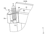
- FIG. 3 is a perspective view of the magnetic sensor 7 and the insulator 25 shown in FIG.
- the upper side (Z1 direction side) in FIG. 1 is the “upper” side
- the lower side (Z2 direction side) in FIG. 1 is the “lower” side.
- the pump device 1 of this embodiment is a type of pump called a can pump (canned motor pump), and includes an impeller 2 and a motor 3 that rotates the impeller 2.
- the motor 3 is a three-phase DC brushless motor.
- the motor 3 includes a rotor 4, a stator 5, a circuit board 6 for controlling the motor 3, and a magnetic sensor 7 for detecting the rotational position of the rotor 4.
- the impeller 2, the rotor 4, the stator 5, the circuit board 6, and the magnetic sensor 7 are arranged inside a case body that includes a housing 8 that constitutes a part of the motor 3 and a case 9 that covers the lower portion of the housing 8. Has been.
- the housing 8 and the case 9 are fixed to each other by screws not shown.
- the case 9 is formed with a fluid suction portion 9a and a fluid discharge portion 9b. Inside the case 9 is formed a pump chamber 10 through which the fluid sucked from the suction portion 9a passes toward the discharge portion 9b.
- the housing 8 includes a partition member 11 having a partition wall 11 a disposed between the rotor 4 and the stator 5 so as to separate the rotor 4 and the stator 5, and a cover 12 fixed to the upper end side of the partition member 11. ing.
- the rotor 4 includes a rotating shaft 14 and a driving magnet 15.
- the rotating shaft 14 is disposed so that the axial direction of the rotating shaft 14 coincides with the vertical direction. That is, the vertical direction is the axial direction of the rotor 4.
- the drive magnet 15 is formed in a cylindrical shape.
- the driving magnet 15 is fixed to the outer peripheral surface of the rotating shaft 14 via a magnet holding member 16.
- N and S poles are alternately magnetized in the circumferential direction of the drive magnet 15. In this embodiment, two magnetic poles, one N pole and one S pole, are magnetized on the outer peripheral surface of the driving magnet 15.
- the impeller 2 is fixed to the lower end of the rotating shaft 14. That is, the impeller 2 is attached to the rotor 4.
- the impeller 2 is disposed inside the pump chamber 10.
- the upper end side of the rotating shaft 14 is rotatably held by the bearing 17.
- the bearing 17 is fixed to the upper end side of the partition wall 11a.
- the lower end side of the rotating shaft 14 is rotatably held by the bearing 18.
- the bearing 18 is held by a bearing holding member 19 fixed to the lower end side of the partition wall 11a. Between the bearing 18 and the bearing holding member 19, a rubber seal member 20 that prevents fluid from flowing into the place where the drive magnet 15 is disposed is disposed.
- the stator 5 includes a driving coil 23, a stator core 24, and an insulator 25 as an insulating member, and is formed in a cylindrical shape as a whole.
- the stator 5 is disposed on the outer peripheral side of the rotor 4 via the partition wall 11a.
- the stator 5 is arrange
- the radial direction of the rotor 4 and the stator 5 is referred to as “radial direction”, and the circumferential direction (circumferential direction) of the rotor 4 and the stator 5 is referred to as “circumferential direction”.
- the partition wall member 11 includes the partition wall 11a.
- the partition wall 11a is formed in a substantially bottomed cylindrical shape, and includes a cylindrical portion 11b and a bottom portion 11c.
- the cylindrical portion 11b is formed in a cylindrical shape.
- the cylindrical portion 11 b is disposed so as to cover the outer peripheral surface of the driving magnet 15, and is disposed between the rotor 4 and the stator 5 in the radial direction.
- the bottom part 11c is formed in a disk shape that closes the upper end of the cylindrical part 11b.
- the bearing 17 is fixed to the lower surface of the bottom portion 11c, and the bearing holding member 19 is fixed to the lower end side of the inner peripheral surface of the cylindrical portion 11b.
- a positioning projection 11d for positioning the circuit board 6 fixed to the partition wall member 11 is formed on the upper surface of the bottom portion 11c so as to protrude upward.
- two positioning protrusions 11d are formed on the bottom surface 11c.
- An inclined surface 11e is formed at the upper end of the outer peripheral surface of the partition wall 11a so that the outer diameter gradually decreases toward the upper side. That is, a tapered inclined surface 11e is formed at the upper end of the outer peripheral surface of the partition wall 11a, and the upper end side portion of the partition wall 11a has a truncated cone shape.
- the partition member 11 includes a cylindrical outer cylinder portion 11f disposed on the outer peripheral side of the partition wall 11a, and a bottom surface portion 11g that connects the lower end of the cylindrical portion 11b and the lower end of the outer cylinder portion 11f.
- the outer cylinder part 11f is formed in a substantially cylindrical shape, for example.
- the height of the outer cylinder portion 11f (the height in the vertical direction) is higher than the height of the partition wall 11a.
- the stator 5 is disposed between the cylindrical portion 11b and the outer cylindrical portion 11f in the radial direction.
- the bottom surface portion 11g is formed in an annular shape.
- the lower side of the bottom surface portion 11g is a pump chamber 10, and a part of the pump chamber 10 is defined by the bottom surface portion 11g. That is, a part of the pump chamber 10 is defined by the partition member 11.
- the bottom surface portion 11g functions to prevent the fluid in the pump chamber 10 from flowing into the locations where the stator 5 and the circuit board 6 are disposed.
- a cylindrical projection 11h rising upward is formed on the bottom surface portion 11g (see FIG. 2), and the circuit board 6 is positioned together with the positioning projection 11d on the tip end side (upper end portion) of the projection 11h.
- a positioning part is formed. That is, the tip of the protrusion 11h is a circuit board positioning portion. In FIG. 1, the protrusion 11h is not shown.
- the circuit board 6 is a rigid board such as a glass epoxy board, and is formed in a flat plate shape.
- the circuit board 6 is disposed above the drive coil 23, the stator core 24, and the insulator 25 so that the thickness direction of the circuit board 6 coincides with the vertical direction.
- the circuit board 6 is disposed below the upper end of the outer cylinder portion 11f. Further, the circuit board 6 is fixed to the bottom portion 11c in a state where the circuit board 6 is positioned by the positioning protrusions 11d and the like. That is, the circuit board 6 is fixed to the partition wall 11a above the bottom portion 11c (that is, outside the partition wall 11a in the vertical direction).
- the upward direction (Z1 direction) of this embodiment is a first direction in which the circuit board 6 is disposed with respect to the partition wall 11a in the axial direction of the rotor 4, and the downward direction (Z2 direction) is The second direction is opposite to the first direction.
- the magnetic sensor 7 is a Hall element.
- the magnetic sensor 7 functions to detect the rotational position of the rotor 4 by detecting the magnetic poles on the outer peripheral surface of the driving magnet 15.
- the motor 3 is a three-phase DC brushless motor, and the motor 3 includes three magnetic sensors 7.
- the magnetic sensor 7 includes a magnetic sensing part 7a formed in a substantially rectangular parallelepiped shape and a plurality of terminals (leads) 7b extending from the magnetic sensing part 7a.
- the magnetic sensor 7 is mounted on the circuit board 6. Specifically, the terminal 7 b is mounted on the circuit board 6 so that the magnetic sensitive part 7 a protrudes downward from the circuit board 6.
- the three magnetic sensors 7 are mounted on the circuit board 6 so that the three magnetic sensors 7 are arranged at a 120 ° pitch with respect to the rotation center of the rotor 4 when viewed from the vertical direction.
- the magnetic sensor 7 may be other than a Hall element.
- the magnetic sensing part 7a is disposed opposite to the outer peripheral surface of the driving magnet 15 via the partition wall 11a. Specifically, the magnetic sensitive surface of the magnetic sensitive portion 7a is disposed opposite to the outer peripheral surface of the driving magnet 15 via the cylindrical portion 11b. Moreover, the magnetic sensitive part 7a is the upper end side part of the cylindrical part 11b, and is arrange
- the cover 12 is formed in a flat, substantially bottomed cylindrical shape.
- the cover 12 is fixed to the upper end side of the inner peripheral surface of the outer cylinder portion 11 f and closes the opening at the upper end of the cover 12. That is, the cover 12 covers the stator 5 and the circuit board 6 from above, and the stator 5 and the circuit board 6 are in a space defined by the cylindrical portion 11b, the outer cylindrical portion 11f, the bottom surface portion 11g, and the cover 12.
- the resin sealing member may be filled in the space defined by the cylindrical portion 11b, the outer cylindrical portion 11f, the bottom surface portion 11g, and the cover 12.
- the stator 5 includes the drive coil 23, the stator core 24, and the insulator 25.
- the stator 5 also includes terminal pins (not shown) to which the end portions of the drive coils 23 are electrically connected.
- the lower end side of the terminal pin is fixed to an insulator 25, and the upper end side of the terminal pin is fixed to the circuit board 6 by soldering.
- the stator core 24 is a laminated core formed by laminating thin magnetic plates made of a magnetic material.
- the stator core 24 includes an outer peripheral ring portion 24a formed in an annular shape and a plurality of salient pole portions 24b protruding from the outer peripheral ring portion 24a toward the inner side in the radial direction.
- the stator core 24 of this embodiment includes three salient pole portions 24b.
- the three salient pole portions 24b are formed at an equiangular pitch, and are arranged at regular intervals in the circumferential direction.
- the tip portion of the salient pole portion 24b is formed in a curved surface shape that has an arc shape with the rotation center of the rotor 4 as the center of curvature when viewed from above and below.
- the insulator 25 is made of an insulating resin material.
- the insulator 25 is attached to each salient pole portion 24 b, and the stator 5 includes three insulators 25.
- the insulator 25 is formed in a cylindrical shape with a flange having flanges at both ends, and the salient pole portion 24b so that the axial direction of the insulator 25 formed in a cylindrical shape matches the radial direction of the stator 5. Is attached.
- the insulator 25 includes an inner flange portion 25a that constitutes an inner portion of the insulator 25 in the radial direction, an outer flange portion 25b that constitutes an outer portion of the insulator 25 in the radial direction, an inner flange portion 25a, and an outer flange portion 25b. It is comprised from the cylinder part 25c (refer FIG. 3) which connects.
- the cylinder part 25c is formed in a square cylinder shape.
- a driving coil 23 is wound around the cylindrical portion 25c. That is, the drive coil 23 is wound around the salient pole portion 24 b via the insulator 25. Switching of energization to the driving coil 23 wound around the three salient pole portions 24 b is performed based on the detection result of the magnetic sensor 7.
- the inner flange portion 25a and the outer flange portion 25b are formed in a flat plate shape orthogonal to the radial direction and are formed in a square ring shape.
- the inner flange portion 25a covers the tip end portion of the salient pole portion 24b having a circular arc shape when viewed from the vertical direction from the outer side in the radial direction.
- the outer flange portion 25b covers a part of the outer peripheral ring portion 24a from the inner side in the radial direction.
- the inner flange portion 25a and the outer flange portion 25b function to prevent the driving coil 23 wound around the cylindrical portion 25c from being collapsed.
- the inner flange portion 25a includes a positioning portion 25d that regulates the position of the magnetic sensing portion 7a in the radial direction. As shown in FIG. 3, the positioning portion 25d is disposed on the upper end side of the inner flange portion 25a. Moreover, the positioning part 25d is arrange
- the positioning portion 25d includes a protruding portion 25e that protrudes from the inner surface of the inner flange portion 25a in the radial direction.
- the positioning portion 25d is formed with a hollow portion 25f that is recessed from the inner side surface of the inner flange portion 25a in the radial direction.
- the part in the circumferential direction of the positioning part 25d which controls the position of the magnetic sensing part 7a can be enlarged because the hollow part 25f is formed.
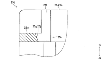
- the protruding portion 25e is formed so that the shape when viewed from above and below is substantially trapezoidal.
- One end surface of the protruding portion 25e in the circumferential direction is arranged on the same plane as one end surface of the inner flange portion 25a in the circumferential direction.
- the upper end surface of the protrusion 25e is disposed below the upper end surface of the inner flange 25a.
- the lower end surface of the protruding portion 25e is disposed on the same plane as the upper surface of the inner peripheral surface of the cylindrical portion 25c.
- the hollow portion 25f is formed so that the shape when viewed from the up-down direction is a substantially triangular shape.
- the recessed portion 25f is formed between the upper end surface of the inner flange portion 25a and the lower end surface of the protruding portion 25e in the vertical direction.
- the inner side surface 25g of the positioning portion 25d in the radial direction is composed of the inner side surface of the protruding portion 25e in the radial direction and the inner side surface of the recessed portion 25f in the radial direction.
- the inner side surface 25g is formed in a curved surface shape. Specifically, the inner side surface 25g is formed in a curved surface having an arc shape whose center of curvature is the rotation center of the rotor 4 when viewed from the vertical direction.
- the inner side surface 25g is a vertical surface that is not inclined with respect to the vertical direction.
- the width of the inner side surface 25g in the circumferential direction is wider than the width of the magnetically sensitive portion 7a in the circumferential direction.
- the range in which the protruding portion 25e is formed in the vertical direction of the positioning portion 25d is defined as the lower end side positioning portion 25h, and the inner side surface of the lower end positioning portion 25h in the radial direction (that is, the protruding portion 25e in the radial direction).
- the width of the lower end side inner side surface 25j in the circumferential direction is The width is wider than the width of the magnetically sensitive portion 7a in the circumferential direction.
- a chamfered portion 25k is formed at the radially inner end of the upper end surface of the positioning portion 25d. That is, a chamfered portion 25k is formed at the radially inner end of the upper end surface of the protrusion 25e and the radially inner end of the upper end surface of the portion of the positioning portion 25d where the recess 25f is formed.
- the radially inner end of the upper end surface of the positioning portion 25d is an inclined surface that is inclined so as to be directed radially outward as it goes upward.
- a chamfered portion is also formed on a portion other than the radially inner end of the upper end surface of the positioning portion 25d.
- the magnetic sensing portion 7a is disposed opposite to the outer peripheral surface of the driving magnet 15 via the partition wall 11a. Specifically, the magnetic sensitive part 7a is disposed between the cylindrical part 11b and the positioning part 25d in the radial direction. More specifically, the magnetic sensing portion 7a is disposed between the outer peripheral surface of the portion on the upper end side of the cylindrical portion 11b and below the inclined surface 11e and the lower end side inner surface 25j in the radial direction. . Moreover, the magnetic sensitive part 7a is mounted on the upper surface of the tip part of the salient pole part 24b.
- FIG. 4 is a view for explaining a method of fixing the circuit board 6 to the partition wall 11a shown in FIG.
- the circuit board 6 on which the magnetic sensor 7 is mounted is fixed to the partition wall 11a of the partition wall member 11 on which the stator 5 is mounted.
- the lower end side (the magnetic sensitive part 7a side) of the magnetic sensor 7 is mounted on the upper end side (the circuit board 6) as shown in FIG.
- the terminal 7b is slightly bent inward in the radial direction so as to be disposed radially inward from the upper end side of the terminal 7b.
- the circuit board 6 is lowered from above the partition wall member 11 with the stator 5 attached until the circuit board 6 is positioned by the positioning protrusions 11d and 11h.
- the circuit board 6 is lowered, as shown by a solid line in FIG. 4B, the radially inner portion of the lower end surface of the magnetic sensing portion 7a comes into contact with the inclined surface 11e of the partition wall 11a, and the magnetic sensing portion 7a.
- the terminal 7b is elastically deformed so as to move outward in the radial direction.
- the terminal 7b is elastically deformed outward in the radial direction until the lower end of the magnetic sensing portion 7a reaches the lower portion of the inclined surface 11e on the outer peripheral side of the cylindrical portion 11b (see the two-dot chain line in FIG. 4B). .
- the magnetic sensing portion 7a is urged radially inward by a terminal 7b that is elastically deformed, and contacts the outer peripheral surface of the cylindrical portion 11b. That is, the magnetic sensitive part 7a is arranged without a gap with respect to the outer peripheral surface of the cylindrical part 11b. That is, the terminal 7b urges the magnetic sensing part 7a inward in the radial direction, and the magnetic sensing part 7a is in contact with the outer peripheral surface of the cylindrical part 11b. Since the magnetic sensing portion 7a of the magnetic sensor 7 is in contact with the outer peripheral surface of the cylindrical portion 11b, the distance from the driving magnet can be reduced, and the magnetic pole on the outer peripheral surface of the driving magnet can be detected appropriately. can do.
- the magnetically sensitive portion 7a When the circuit board 6 is lowered until it is positioned by the positioning protrusions 11d and 11h, the magnetically sensitive portion 7a has a cylindrical portion 11b and a lower end side inner peripheral surface 25j in the radial direction, as indicated by a broken line in FIG. Between. In this state, the tip portions of the positioning projections 11d and the projections 11h are crushed while being heated, and the circuit board 6 is welded and fixed to the partition walls 11a. Alternatively, the circuit board 6 is fixed to the partition wall 11a with screws or the like not shown.
- the tapered inclined surface 11e is formed at the upper end of the outer peripheral surface of the partition wall 11a, and the circuit board 6 on which the magnetic sensor 7 is mounted is fixed to the partition wall 11a from above.
- the magnetic sensing portion 7a of the magnetic sensor 7 contacts the inclined surface 11e and is guided along the inclined surface 11e to the lower portion of the inclined surface 11e on the outer peripheral side of the cylindrical portion 11b. Therefore, in this embodiment, when the circuit board 6 on which the magnetic sensor 7 is mounted is fixed to the partition wall 11a from the upper side, the magnetic sensor 7 cannot be seen from the upper side, but the magnetic sensor 7 is utilized by using the inclined surface 11e. It is possible to smoothly guide the magnetic sensing portion 7a to the outer peripheral side of the cylindrical portion 11b while preventing excessive bending of the terminal 7b.
- the inner flange portion 25a of the insulator 25 is provided with a positioning portion 25d that regulates the position of the magnetic sensing portion 7a in the radial direction.
- the magnetic sensing portion 7a is positioned with the cylindrical portion 11b in the radial direction. It is arrange
- the magnetically sensitive portion 7a is disposed between the cylindrical portion 11b and the positioning portion 25d in the radial direction, it is defined by the cylindrical portion 11b, the outer cylindrical portion 11f, the bottom surface portion 11g, and the cover 12.
- a chamfered portion 25k is formed at the radially inner end of the upper end surface of the positioning portion 25d.
- a chamfered portion 7c is formed at the radially inner end of the lower end surface of the magnetic sensitive portion 7a. Therefore, in this embodiment, when the circuit board 6 on which the magnetic sensor 7 is mounted is fixed to the partition wall 11a from above, the magnetic sensitive portion 7a is likely to enter between the cylindrical portion 11b and the positioning portion 25d in the radial direction.
- the circumferential width of the inner surface 25g of the positioning portion 25d is wider than the width of the magnetically sensitive portion 7a in the circumferential direction. Therefore, in the present embodiment, it is possible to shift the relative position in the circumferential direction of the magnetic sensing portion 7a with respect to the stator 5 in accordance with the characteristics of the motor 3 and the like. Therefore, in this embodiment, the common insulator 25 can be used for the motors 3 having different characteristics and the like, and as a result, the versatility of the insulator 25 can be enhanced. Further, in the present embodiment, the inner side surface 25g is formed in a curved surface shape having an arc shape with the rotation center of the rotor 4 as the center of curvature when viewed from the vertical direction.
- the inner flange 25a is formed in a flat plate shape perpendicular to the radial direction. Therefore, in this embodiment, it is possible to easily form the inner flange portion 25a as compared with the case where the inner flange portion 25a is formed in a curved plate shape.
- the positioning portion 25d includes the protruding portion 25e that protrudes from the inner side surface of the inner flange portion 25a in the radial direction. Therefore, even if the inner flange portion 25a is formed in a flat plate shape, the protruding portion 25e. It is possible to regulate the position of the magnetically sensitive portion 7a in the radial direction by using.
- the upper end surface of the protruding portion 25e is disposed below the upper end surface of the inner flange portion 25a.
- the upper end surface of the protruding portion 25e is the inner flange portion 25a. It may be arranged on the same plane as the upper end surface of.
- the inner side surface 25g of the positioning portion 25d is a vertical surface that is not inclined with respect to the vertical direction, but the inner side surface 25g is directed downward as shown in FIG. Therefore, it may be an inclined surface that inclines toward the inner side in the radial direction.
- the magnetic sensitive part 7a can easily enter between the cylindrical part 11b and the positioning part 25d in the radial direction. 5 and 6, the same reference numerals are assigned to the same configurations as those described above.
- the inner flange portion 25a is formed in a flat plate shape orthogonal to the radial direction, and the outer surface of the inner flange portion 25a in the radial direction is formed in a planar shape orthogonal to the radial direction.
- the outer side surface of the inner flange portion 25a in the radial direction may be formed in a curved surface shape having an arc shape with the rotation center of the rotor 4 as the center of curvature when viewed from the vertical direction.
- the positioning portion 25d may not include the protruding portion 25e.
- the recessed portion 25f may not be formed in the positioning portion 25d.
- the circumferential width of the inner side surface 25g of the positioning portion 25d is wider than the width of the magnetically sensitive portion 7a in the circumferential direction, but the circumferential width of the inner side surface 25g is larger in the circumferential direction. It may be equal to the width of the magnetic part 7a.
- the stator core 24 includes the three salient pole portions 24b, but the number of salient pole portions 24b included in the stator core 24 may be four or more. If the number of salient pole portions 24b of the stator core 24 is increased, the interval between the salient pole portions 24b in the circumferential direction is narrowed, and therefore the position of the magnetically sensitive portion 7a in the circumferential direction and the radial direction is easily determined automatically. . On the other hand, when the number of the salient pole portions 24b is three as in the above-described form, the interval between the salient pole portions 24b in the circumferential direction is widened. Is difficult to determine automatically. Therefore, the positioning portion 25d functions more effectively when the number of salient pole portions 24b is small.
- the magnetic sensing portion 7a is placed on the upper surface of the tip portion of the salient pole portion 24b, but the convex portion on which the magnetic sensing portion 7a is placed is formed on the inner side surface of the inner flange portion 25a in the radial direction. Also good.
- a convex portion that regulates the position of the magnetic sensitive portion 7a in the circumferential direction may be formed on the inner side surface 25g of the positioning portion 25d.
- the motor 3 is used for the pump apparatus 1, the motor 3 may be used other than the pump apparatus 1.
Landscapes
- Engineering & Computer Science (AREA)
- Power Engineering (AREA)
- Mechanical Engineering (AREA)
- General Engineering & Computer Science (AREA)
- Microelectronics & Electronic Packaging (AREA)
- Brushless Motors (AREA)
- Structures Of Non-Positive Displacement Pumps (AREA)
Abstract
ロータとステータとの間に配置される隔壁を有するモータにおいて、ロータの駆動用磁石の外周面に隔壁を介して対向配置される磁気センサの感磁部と駆動用磁石との径方向における相対位置精度を高めることが可能なモータを提供する。このモータでは、ロータとステータ5との間に配置される隔壁11aは、円筒部11bと、円筒部11bのZ1方向端を塞ぐとともに回路基板が固定される底部11cとを備えており、隔壁11aの外周面のZ1方向端には、傾斜面11eが形成されている。絶縁部材25は、内側鍔部25aを備えており、内側鍔部25aは、径方向における磁気センサ7の感磁部7aの位置を規制する位置決め部25dを備えている。回路基板には、感磁部7aが回路基板からZ2方向側へ突出するように磁気センサ7の端子7bが実装されており、感磁部7aは、径方向において円筒部11bと位置決め部25dとの間に配置されている。
Description
本発明は、ロータとステータとの間に配置される隔壁を有するモータに関する。また、本発明は、かかるモータを備えるポンプ装置に関する。
従来、羽根車およびロータが配置されるポンプ室と、ポンプ室の外側に配置されるステータおよび回路基板とを備えるポンプ装置が知られている(たとえば、特許文献1参照)。特許文献1に記載のポンプ装置では、ステータおよび回路基板とポンプ室との間に、ステータおよび回路基板の配置箇所への流体の流入を防止する隔壁が配置されている。ロータは、駆動用磁石を備えている。ステータは、略円筒状に形成されており、駆動用コイルと、絶縁性部材を介して駆動用コイルが巻回されるステータコアとを備えている。ステータコアは、円環状の円環部と、円環部からロータの径方向の内側へ突出する複数の突極部とを備えている。絶縁性部材は、ロータの径方向における内側に配置される内側絶縁部と、径方向の外側に配置される外側絶縁部と、内側絶縁部と外側絶縁部とを繋ぐ連結絶縁部とから構成されている。隔壁は、有底円筒状に形成されている。
また、特許文献1に記載のポンプ装置では、回路基板は、平板状に形成されており、ステータの軸方向と回路基板の厚さ方向とが一致するように隔壁の底部に固定されている。回路基板には、隔壁を介して駆動用磁石の外周面に対向配置される感磁部を有する磁気センサが実装されている。具体的には、感磁部が回路基板から突出するように磁気センサの端子が回路基板に実装されており、感磁部は、ロータの周方向で隣り合う内側絶縁部の端面の間に配置されている。特許文献1に記載のポンプ装置では、ロータとステータとによって三相ブラシレスモータが構成されている。また、磁気センサは、駆動用磁石の外周面の磁極を検知することでロータの回転位置を検知する機能を果たしており、磁気センサでの検知結果に基づいて駆動用コイルに供給される電流が制御されている。
特許文献1に記載のポンプ装置では、駆動用磁石の外周面の磁極を検知する磁気センサの感磁部が隔壁を介して駆動用磁石の外周面に対向しており、隔壁の厚さ分、駆動用磁石の外周面と感磁部との距離が遠くなっている。そのため、このポンプ装置では、感磁部の配置位置がロータの径方向の外側へずれて、駆動用磁石の外周面と感磁部との距離がさらに遠くなると、磁気センサによって駆動用磁石の外周面の磁極を適切に検知できなくなるおそれがある。
そこで、本発明の課題は、ロータとステータとの間に配置される隔壁を有するモータにおいて、ロータの駆動用磁石の外周面に隔壁を介して対向配置される磁気センサの感磁部と駆動用磁石との径方向における相対位置精度を高めることが可能なモータを提供することにある。また、本発明は、かかるモータを備えるポンプ装置を提供することにある。
上記の課題を解決するため、本発明のモータは、駆動用磁石を有するロータと、駆動用コイルを有しロータの外周側に配置されるステータと、ロータとステータとの間に配置される略有底円筒状の隔壁を有する隔壁部材と、ロータの軸方向における隔壁の外側で隔壁に固定される回路基板と、隔壁を介して駆動用磁石の外周面に対向配置される感磁部を有する磁気センサとを備え、軸方向のうちの隔壁に対して回路基板が配置される方向を第1方向とし、第1方向の反対方向を第2方向とすると、ステータは、絶縁部材と、絶縁部材を介して駆動用コイルが巻回される複数の突極部を有するステータコアとを備え、ステータコアは、環状に形成される外周環部と、外周環部からロータの径方向の内側に向かって突出する複数の突極部とを備え、絶縁部材は、径方向における絶縁部材の内側部分を構成する内側鍔部を備え、隔壁は、ロータとステータとの間に配置される円筒状の円筒部と、円筒部の第1方向端を塞ぐとともに回路基板が固定される円板状の底部とを備え、隔壁の外周面の第1方向端には、第1方向側に向かうにしたがって外径が次第に小さくなる傾斜面が形成され、内側鍔部は、径方向における感磁部の位置を規制する位置決め部を備え、回路基板には、感磁部が回路基板から第2方向側へ突出するように磁気センサの端子が実装され、感磁部は、径方向において円筒部と位置決め部との間に配置されていることを特徴とする。
本発明のモータでは、隔壁は、ロータとステータとの間に配置される円筒状の円筒部と、円筒部の第1方向端を塞ぐとともに回路基板が固定される円板状の底部とを備えており、隔壁を介して駆動用磁石の外周面に対向配置される磁気センサの感磁部が第2方向側へ突出するように磁気センサの端子が回路基板に実装されている。また、本発明では、隔壁の外周面の第1方向端に、第1方向側に向かうにしたがって外径が次第に小さくなる傾斜面が形成されている。そのため、本発明では、磁気センサが実装された回路基板を第1方向側から隔壁の底部に固定する際に、隔壁の傾斜面を利用して、磁気センサの端子の過剰な湾曲を防止しつつ円筒部の外周側へ感磁部を円滑に案内することが可能になる。
また、本発明では、径方向における絶縁部材の内側部分を構成する内側鍔部は、径方向における感磁部の位置を規制する位置決め部を備えており、感磁部は、径方向において円筒部と位置決め部との間に配置されている。そのため、本発明では、隔壁の傾斜面を利用して円筒部の外周側に案内された感磁部を、円筒部の外周面と位置決め部とによって径方向で精度良く位置決めすることが可能になる。したがって、本発明では、駆動用磁石の外周面に隔壁を介して対向配置される磁気センサの感磁部と駆動用磁石との径方向における相対位置精度を高めることが可能になる。
本発明において、径方向における位置決め部の内側面の、ロータの周方向の幅は、周方向における感磁部の幅よりも広くなっていることが好ましい。このように構成すると、モータの特性等に応じて、ステータに対する感磁部の周方向の相対位置をずらすことが可能になる。したがって、特性等の相違するモータに共通の絶縁部材を使用することが可能になり、絶縁部材の汎用性を高めることが可能になる。
本発明において、径方向における位置決め部の内側面は、軸方向から見たときの形状がロータの回転中心を曲率中心とする円弧状をなす曲面状に形成されていることが好ましい。このように構成すると、モータの特性等に応じてステータに対する感磁部の周方向の相対位置をずらすことが可能となっていても、感磁部と駆動用磁石との径方向における相対位置のずれを抑制して感磁部と駆動用磁石との径方向における相対位置精度を高めることが可能になる。
本発明において、位置決め部の第1方向側の端面の、径方向の内側端には、面取り部が形成されていることが好ましい。また、本発明において、径方向における位置決め部の内側面は、第2方向側に向かうにしたがって径方向の内側へ向かうように傾斜する傾斜面となっていることが好ましい。このように構成すると、磁気センサが実装された回路基板を第1方向側から隔壁の底部に固定する際に、径方向における円筒部と位置決め部との間に感磁部が入り込みやすくなる。
本発明において、たとえば、内側鍔部は、径方向に直交する平板状に形成され、位置決め部は、径方向における内側鍔部の内側面から突出する突出部を備えている。この場合には、たとえば、内側鍔部が曲板状に形成されている場合と比較して、内側鍔部を容易に形成することが可能になる。また、この場合には、内側鍔部が平板状に形成されていても、突出部を利用して径方向における感磁部の位置を規制することが可能になる。
本発明において、たとえば、突出部の第1方向側の端面は、内側鍔部の第1方向側の端面と同一平面上に配置されている。
本発明において、感磁部の第2方向側の端面の、径方向の内側端には、面取り部が形成されていることが好ましい。このように構成すると、磁気センサが実装された回路基板を第1方向側から隔壁の底部に固定する際に、径方向における円筒部と位置決め部との間に感磁部が入り込みやすくなる。
本発明において、端子は、感磁部を径方向の内側に付勢しており、感磁部は、円筒部の外周面に接触していることが好ましい。
本発明において、位置決め部には、径方向における内側鍔部の内側面から窪む窪み部が形成されていることが好ましい。
本発明において、底部における第1方向側の面には、隔壁部材に固定される回路基板を位置決めするための位置決め用突起が第1方向側へ突出するように形成されていることが好ましい。
本発明において、隔壁部材は、隔壁の外周側に配置される筒状の外筒部と、円筒部の下端と外筒部の下端とを繋ぐ底面部とを備え、底面部には、上側に向かって立ち上がる円柱状の突起が形成されており、突起の先端部側には、位置決め用突起とともに回路基板を位置決めする回路基板位置決め部が形成されていることが好ましい。
本発明において、ステータコアは、3個の突極部を備え、3個の突極部は、等角度ピッチで形成されており、周方向において一定の間隔で配置され、ステータは、3個の突極部のそれぞれに取り付けられた3個の絶縁部材を備え、かつ、3個の絶縁部材を介して3個の突極部にそれぞれ巻回された3個の駆動用コイルを有し、3個の絶縁部材には、それぞれの絶縁部材に1個ずつ形成された3個の内側鍔部を備え、3個の内側鍔部には、それぞれの内側鍔部に1個ずつ形成された3個の位置決め部を備え、3個の位置決め部には、それぞれの位置決め部に1個ずつ配置された3個の磁気センサを備えていることが好ましい。
本発明のモータは、ロータに取り付けられる羽根車を備えるポンプ装置であって、隔壁部材によって、羽根車が配置されるとともに流体が通過するポンプ室の一部が画定されているポンプ装置に用いることができる。このポンプ装置では、駆動用磁石の外周面に隔壁を介して対向配置される磁気センサの感磁部と駆動用磁石との径方向における相対位置精度を高めることが可能になる。
以上のように、本発明では、ロータの駆動用磁石の外周面に隔壁を介して対向配置される磁気センサの感磁部と駆動用磁石との径方向における相対位置精度を高めることが可能になる。
以下、図面を参照しながら、本発明の実施の形態を説明する。
(ポンプ装置の全体構成)
図1は、本発明の実施の形態にかかるポンプ装置1の断面図である。図2は、図1に示すステータ5、隔壁部材11および磁気センサ7の斜視図である。図3は、図2に示す磁気センサ7およびインシュレータ25の斜視図である。以下の説明では、図1の上側(Z1方向側)を「上」側とし、図1の下側(Z2方向側)を「下」側とする。
図1は、本発明の実施の形態にかかるポンプ装置1の断面図である。図2は、図1に示すステータ5、隔壁部材11および磁気センサ7の斜視図である。図3は、図2に示す磁気センサ7およびインシュレータ25の斜視図である。以下の説明では、図1の上側(Z1方向側)を「上」側とし、図1の下側(Z2方向側)を「下」側とする。
本形態のポンプ装置1は、キャンドポンプ(キャンドモータポンプ)と呼ばれるタイプのポンプであり、羽根車2と、羽根車2を回転させるモータ3とを備えている。モータ3は、三相のDCブラシレスモータである。このモータ3は、ロータ4と、ステータ5と、モータ3を制御するための回路基板6と、ロータ4の回転位置を検知するための磁気センサ7とを備えている。羽根車2、ロータ4、ステータ5、回路基板6および磁気センサ7は、モータ3の一部を構成するハウジング8と、ハウジング8の下部を覆うケース9とによって構成されるケース体の内部に配置されている。ハウジング8とケース9とは、図示を省略するネジによって互いに固定されている。
ケース9には、流体の吸入部9aと、流体の吐出部9bとが形成されている。ケース9の内部には、吸入部9aから吸入された流体が吐出部9bに向かって通過するポンプ室10が形成されている。ハウジング8は、ロータ4とステータ5とを隔てるようにロータ4とステータ5との間に配置される隔壁11aを有する隔壁部材11と、隔壁部材11の上端側に固定されるカバー12とを備えている。
ロータ4は、回転軸14と、駆動用磁石15とを備えている。回転軸14は、回転軸14の軸方向と上下方向とが一致するように配置されている。すなわち、上下方向は、ロータ4の軸方向である。駆動用磁石15は、円筒状に形成されている。この駆動用磁石15は、磁石保持部材16を介して回転軸14の外周面に固定されている。駆動用磁石15の外周面には、駆動用磁石15の円周方向においてN極とS極とが交互に着磁されている。本形態では、1個のN極と1個のS極との2つの磁極が駆動用磁石15の外周面に着磁されている。
回転軸14の下端部には、羽根車2が固定されている。すなわち、羽根車2は、ロータ4に取り付けられている。羽根車2は、ポンプ室10の内部に配置されている。回転軸14の上端側は、軸受17に回転可能に保持されている。軸受17は、隔壁11aの上端側に固定されている。回転軸14の下端側は、軸受18に回転可能に保持されている。軸受18は、隔壁11aの下端側に固定される軸受保持部材19に保持されている。軸受18と軸受保持部材19との間には、駆動用磁石15の配置箇所への流体の流入を阻止するゴム製のシール部材20が配置されている。
ステータ5は、駆動用コイル23と、ステータコア24と、絶縁部材としてのインシュレータ25とを備えており、全体として筒状に形成されている。このステータ5は、隔壁11aを介して、ロータ4の外周側に配置されている。また、ステータ5は、筒状に形成されるステータ5の軸方向と上下方向とが一致するように配置されている。ステータ5の具体的な構成については後述する。なお、以下の説明では、ロータ4およびステータ5の径方向を「径方向」とし、ロータ4およびステータ5の周方向(円周方向)を「周方向」とする。
上述のように、隔壁部材11は、隔壁11aを備えている。隔壁11aは、略有底円筒状に形成されており、円筒部11bと底部11cとを備えている。円筒部11bは、円筒状に形成されている。この円筒部11bは、駆動用磁石15の外周面を覆うように配置されており、径方向におけるロータ4とステータ5との間に配置されている。底部11cは、円筒部11bの上端を塞ぐ円板状に形成されている。軸受17は、底部11cの下面に固定され、軸受保持部材19は、円筒部11bの内周面の下端側に固定されている。
底部11cの上面には、隔壁部材11に固定される回路基板6を位置決めするための位置決め用突起11dが上側へ突出するように形成されている。本形態では、底部11cの状面に位置決め用突起11dが2つ形成されている。隔壁11aの外周面の上端には、上側に向かうにしたがって外径が次第に小さくなる傾斜面11eが形成されている。すなわち、隔壁11aの外周面の上端には、テーパー状の傾斜面11eが形成されており、隔壁11aの上端側部分は、円錐台状となっている。
また、隔壁部材11は、隔壁11aの外周側に配置される筒状の外筒部11fと、円筒部11bの下端と外筒部11fの下端とを繋ぐ底面部11gとを備えている。外筒部11fは、たとえば、略円筒状に形成されている。外筒部11fの高さ(上下方向の高さは)、隔壁11aの高さよりも高くなっている。ステータ5は、径方向において円筒部11bと外筒部11fとの間に配置されている。
底面部11gは、円環状に形成されている。底面部11gの下側は、ポンプ室10となっており、底面部11gによってポンプ室10の一部が画定されている。すなわち、隔壁部材11によってポンプ室10の一部が画定されている。底面部11gは、ステータ5および回路基板6の配置箇所へのポンプ室10内の流体の流入を防止する機能を果たしている。底面部11gには、上側に向かって立ち上がる円柱状の突起11hが形成されており(図2参照)、突起11hの先端部側(上端部)には、位置決め用突起11dとともに回路基板6を位置決めする位置決め部が形成されている。つまり、突起11hの先端は、回路基板位置決め部となっている。なお、図1では、突起11hの図示を省略している。
回路基板6は、ガラスエポキシ基板等のリジッド基板であり、平板状に形成されている。この回路基板6は、回路基板6の厚さ方向と上下方向とが一致するように、駆動用コイル23、ステータコア24およびインシュレータ25よりも上側に配置されている。また、回路基板6は、外筒部11fの上端よりも下側に配置されている。また、回路基板6は、位置決め用突起11d等によって位置決めされた状態で、底部11cに固定されている。すなわち、回路基板6は、底部11cよりも上側で(すなわち、上下方向における隔壁11aの外側)で隔壁11aに固定されている。本形態の上方向(Z1方向)は、ロータ4の軸方向のうちの隔壁11aに対して回路基板6が配置される方向である第1方向となっており、下方向(Z2方向)は、第1方向の反対方向である第2方向となっている。
磁気センサ7は、ホール素子である。この磁気センサ7は、駆動用磁石15の外周面の磁極を検知することでロータ4の回転位置を検知する機能を果たしている。上述のように、モータ3は、三相のDCブラシレスモータであり、モータ3は、3個の磁気センサ7を備えている。磁気センサ7は、略直方体状に形成される感磁部7aと、感磁部7aから伸びる複数の端子(リード)7bとを備えている。この磁気センサ7は、回路基板6に実装されている。具体的には、感磁部7aが回路基板6から下側へ突出するように端子7bが回路基板6に実装されている。また、上下方向から見たときにロータ4の回転中心に対して3個の磁気センサ7が120°ピッチで配置されるように、3個の磁気センサ7が回路基板6に実装されている。なお、磁気センサ7は、ホール素子以外のものであっても良い。
感磁部7aは、隔壁11aを介して駆動用磁石15の外周面に対向配置されている。具体的には、感磁部7aの感磁面が、円筒部11bを介して駆動用磁石15の外周面に対向配置されている。また、感磁部7aは、円筒部11bの上端側部分であって、かつ、傾斜面11eよりも下側の部分の外周側に配置されている。感磁部7aの下端面の、径方向の内側端には、面取り部7cが形成されている(図4参照)。すなわち、感磁部7aの下端面の、径方向の内側端は、径方向の内側に向かうにしたがって上側へ向かうように傾斜する傾斜面となっている。
カバー12は、扁平な略有底円筒状に形成されている。このカバー12は、外筒部11fの内周面の上端側に固定されており、カバー12の上端の開口を塞いでいる。すなわち、カバー12は、ステータ5および回路基板6を上側から覆っており、ステータ5および回路基板6は、円筒部11b、外筒部11f、底面部11gおよびカバー12によって画定される空間の中に配置されている。なお、円筒部11b、外筒部11f、底面部11gおよびカバー12によって画定される空間の内部に、樹脂封止部材が充填されていても良い。
(ステータの構成)
上述のように、ステータ5は、駆動用コイル23とステータコア24とインシュレータ25とを備えている。また、ステータ5は、駆動用コイル23の端部が電気的に接続される端子ピン(図示省略)を備えている。この端子ピンの下端側は、たとえば、インシュレータ25に固定されており、端子ピンの上端側は、回路基板6に半田付けされて固定されている。
上述のように、ステータ5は、駆動用コイル23とステータコア24とインシュレータ25とを備えている。また、ステータ5は、駆動用コイル23の端部が電気的に接続される端子ピン(図示省略)を備えている。この端子ピンの下端側は、たとえば、インシュレータ25に固定されており、端子ピンの上端側は、回路基板6に半田付けされて固定されている。
ステータコア24は、磁性材料からなる薄い磁性板が積層されて形成された積層コアである。このステータコア24は、環状に形成される外周環部24aと、外周環部24aから径方向の内側に向かって突出する複数の突極部24bとを備えている。本形態のステータコア24は、3個の突極部24bを備えている。3個の突極部24bは、等角度ピッチで形成されており、周方向において一定の間隔で配置されている。突極部24bの先端部分は、上下方向から見たときの形状がロータ4の回転中心を曲率中心とする円弧状をなす曲面状に形成されている。
インシュレータ25は、絶縁性を有する樹脂材料で形成されている。このインシュレータ25は、突極部24bごとに取り付けられており、ステータ5は、3個のインシュレータ25を備えている。また、インシュレータ25は、両端に鍔部を有する鍔付きの筒状に形成されており、筒状に形成されるインシュレータ25の軸方向とステータ5の径方向とが一致するように突極部24bに取り付けられている。すなわち、インシュレータ25は、径方向におけるインシュレータ25の内側部分を構成する内側鍔部25aと、径方向におけるインシュレータ25の外側部分を構成する外側鍔部25bと、内側鍔部25aと外側鍔部25bとを繋ぐ筒部25c(図3参照)とから構成されている。
筒部25cは、四角筒状に形成されている。筒部25cには、駆動用コイル23が巻回されている。すなわち、駆動用コイル23は、インシュレータ25を介して突極部24bに巻回されている。3個の突極部24bに巻回される駆動用コイル23への通電の切替は、磁気センサ7での検知結果に基づいて行われる。内側鍔部25aおよび外側鍔部25bは、径方向に直交する平板状に形成されるとともに四角環状に形成されている。内側鍔部25aは、上下方向から見たときの形状が円弧状となる突極部24bの先端部分を径方向の外側から覆っている。外側鍔部25bは、外周環部24aの一部分を径方向の内側から覆っている。内側鍔部25aおよび外側鍔部25bは、筒部25cに巻回される駆動用コイル23の巻崩れを防止する機能を果たしている。
内側鍔部25aは、径方向における感磁部7aの位置を規制する位置決め部25dを備えている。図3に示すように、位置決め部25dは、内側鍔部25aの上端側に配置されている。また、位置決め部25dは、周方向における内側鍔部25aの一端側に配置されている。すなわち、内側鍔部25aの、上端側かつ周方向における一端側の角部が位置決め部25dとなっている。位置決め部25dは、径方向における内側鍔部25aの内側面から突出する突出部25eを備えている。また、位置決め部25dには、径方向における内側鍔部25aの内側面から窪む窪み部25fが形成されている。なお、窪み部25fが形成されていることで、感磁部7aの位置を規制する位置決め部25dの周方向における部分を広くすることができる。
突出部25eは、上下方向から見たときの形状が略台形状となるように形成されている。周方向における突出部25eの一端面は、周方向における内側鍔部25aの一端面と同一平面上に配置されている。突出部25eの上端面は、内側鍔部25aの上端面よりも下側に配置されている。突出部25eの下端面は、筒部25cの内周面の上面と同一平面上に配置されている。窪み部25fは、上下方向から見たときの形状が略三角形状となるように形成されている。この窪み部25fは、上下方向において、内側鍔部25aの上端面と突出部25eの下端面との間に形成されている。
径方向における位置決め部25dの内側面25gは、径方向における突出部25eの内側面と径方向における窪み部25fの内側面とから構成されている。この内側面25gは、曲面状に形成されている。具体的には、内側面25gは、上下方向から見たときの形状がロータ4の回転中心を曲率中心とする円弧状をなす曲面状に形成されている。また、内側面25gは、上下方向に対して傾斜していない垂直面となっている。
周方向における内側面25gの幅は、周方向における感磁部7aの幅よりも広くなっている。具体的には、位置決め部25dの、上下方向において突出部25eが形成されている範囲を下端側位置決め部25hとし、径方向における下端側位置決め部25hの内側面(すなわち、径方向における突出部25eの内側面、および、径方向における窪み部25fの内側面の、上下方向において突出部25eが形成されている範囲)を下端側内側面25jとすると、周方向における下端側内側面25jの幅は、周方向における感磁部7aの幅よりも広くなっている。
位置決め部25dの上端面の、径方向の内側端には、面取り部25kが形成されている。すなわち、突出部25eの上端面の径方向の内側端と、位置決め部25dの、窪み部25fが形成されている部分の上端面の径方向の内側端とには、面取り部25kが形成されており、位置決め部25dの上端面の、径方向の内側端は、上側に向かうにしたがって径方向の外側に向かうように傾斜する傾斜面となっている。なお、本形態では、位置決め部25dの上端面の、径方向の内側端以外の部分にも、面取り部が形成されている。
上述のように、感磁部7aは、隔壁11aを介して駆動用磁石15の外周面に対向配置されている。具体的には、感磁部7aは、径方向において円筒部11bと位置決め部25dとの間に配置されている。より具体的には、感磁部7aは、径方向において、円筒部11bの上端側かつ傾斜面11eよりも下側の部分の外周面と、下端側内側面25jとの間に配置されている。また、感磁部7aは、突極部24bの先端部分の上面に載っている。
(回路基板の固定方法)
図4は、図1に示す隔壁11aへの回路基板6の固定方法を説明するための図である。
図4は、図1に示す隔壁11aへの回路基板6の固定方法を説明するための図である。
磁気センサ7が実装された状態の回路基板6は、ステータ5が取り付けられた状態の隔壁部材11の隔壁11aに固定される。隔壁11aに回路基板6を固定する前には、図4(A)に示すように、磁気センサ7の下端側(感磁部7a側)が磁気センサ7の上端側(回路基板6に実装される端子7bの上端側)よりも径方向の内側に配置されるように、端子7bを若干、径方向の内側に曲げる。
その後、ステータ5が取り付けられた状態の隔壁部材11の上方から、回路基板6を、位置決め用突起11dおよび突起11hによって位置決めされるまで下げていく。回路基板6を下げていくと、図4(B)の実線で示すように、感磁部7aの下端面の径方向の内側部分が隔壁11aの傾斜面11eに接触して、感磁部7aが径方向の外側へ移動するように端子7bが弾性変形する。端子7bは、円筒部11bの外周側の、傾斜面11eの下側部分に感磁部7aの下端が到達するまで径方向の外側へ弾性変形する(図4(B)の二点鎖線参照)。感磁部7aは、弾性変形する端子7bによって径方向の内側に付勢されており、円筒部11bの外周面に接触する。すなわち、感磁部7aは、円筒部11bの外周面に対して隙間のない状態で配置される。つまり、端子7bは、感磁部7aを径方向の内側に付勢しており、感磁部7aは、円筒部11bの外周面に接触している。なお、磁気センサ7の感磁部7aが円筒部11bの外周面に接触していることで、駆動用磁石との距離を近くすることができ、駆動用磁石の外周面の磁極を適切に検知することができる。
位置決め用突起11dおよび突起11hによって位置決めされるまで回路基板6が下がると、感磁部7aは、図4(B)の破線で示すように、径方向において円筒部11bと下端側内周面25jとの間に配置される。この状態で、位置決め用突起11dおよび突起11hの先端部を加熱しながら潰して隔壁11aに回路基板6を溶着固定する。あるいは、図示を省略するネジ等によって、隔壁11aに回路基板6を固定する。
(本形態の主な効果)
以上説明したように、本形態では、隔壁11aの外周面の上端にテーパー状の傾斜面11eが形成されており、磁気センサ7が実装された状態の回路基板6を上側から隔壁11aに固定する際に、磁気センサ7の感磁部7aは、傾斜面11eに接触し、傾斜面11eに沿って、円筒部11bの外周側の、傾斜面11eの下側部分まで案内されている。そのため、本形態では、磁気センサ7が実装された回路基板6を上側から隔壁11aに固定する際に、上側から磁気センサ7を見ることはできないが、傾斜面11eを利用して、磁気センサ7の端子7bの過剰な湾曲を防止しつつ円筒部11bの外周側へ感磁部7aを円滑に案内することが可能になる。
以上説明したように、本形態では、隔壁11aの外周面の上端にテーパー状の傾斜面11eが形成されており、磁気センサ7が実装された状態の回路基板6を上側から隔壁11aに固定する際に、磁気センサ7の感磁部7aは、傾斜面11eに接触し、傾斜面11eに沿って、円筒部11bの外周側の、傾斜面11eの下側部分まで案内されている。そのため、本形態では、磁気センサ7が実装された回路基板6を上側から隔壁11aに固定する際に、上側から磁気センサ7を見ることはできないが、傾斜面11eを利用して、磁気センサ7の端子7bの過剰な湾曲を防止しつつ円筒部11bの外周側へ感磁部7aを円滑に案内することが可能になる。
また、本形態では、インシュレータ25の内側鍔部25aに、径方向における感磁部7aの位置を規制する位置決め部25dが形成されており、感磁部7aは、径方向において円筒部11bと位置決め部25dとの間に配置されている。そのため、本形態では、傾斜面11eに沿って円筒部11bの外周側に案内された感磁部7aを円筒部11bと位置決め部25dとによって径方向で精度良く位置決めすることが可能になる。したがって、本形態では、駆動用磁石15の外周面に隔壁11aを介して対向配置される感磁部7aと駆動用磁石15との径方向における相対位置精度を高めることが可能になる。
また、本形態では、径方向において円筒部11bと位置決め部25dとの間に感磁部7aが配置されているため、円筒部11b、外筒部11f、底面部11gおよびカバー12によって画定される空間の内部に樹脂封止部材が充填される場合には、樹脂封止部材を充填する際の感磁部7aの位置ずれを抑制することが可能になる。
本形態では、位置決め部25dの上端面の、径方向の内側端に面取り部25kが形成されている。また、本形態では、感磁部7aの下端面の、径方向の内側端に面取り部7cが形成されている。そのため、本形態では、磁気センサ7が実装された回路基板6を上側から隔壁11aに固定する際に、径方向における円筒部11bと位置決め部25dとの間に感磁部7aが入り込みやすくなる。
本形態では、位置決め部25dの内側面25gの周方向の幅は、周方向における感磁部7aの幅よりも広くなっている。そのため、本形態では、モータ3の特性等に応じて、ステータ5に対する感磁部7aの周方向の相対位置をずらすことが可能になる。したがって、本形態では、特性等の相違するモータ3に共通のインシュレータ25を使用することが可能になり、その結果、インシュレータ25の汎用性を高めることが可能になる。また、本形態では、内側面25gは、上下方向から見たときの形状がロータ4の回転中心を曲率中心とする円弧状をなす曲面状に形成されているため、ステータ5に対する感磁部7aの周方向の相対位置をずらすことが可能となっていても、感磁部7aと駆動用磁石15との径方向における相対位置のずれを抑制して感磁部7aと駆動用磁石15との径方向における相対位置精度を高めることが可能になる。
本形態では、内側鍔部25aは、径方向に直交する平板状に形成されている。そのため、本形態では、内側鍔部25aが曲板状に形成されている場合と比較して、内側鍔部25aを容易に形成することが可能になる。また、本形態では、位置決め部25dは、径方向における内側鍔部25aの内側面から突出する突出部25eを備えているため、内側鍔部25aが平板状に形成されていても、突出部25eを利用して径方向における感磁部7aの位置を規制することが可能になる。
(他の実施の形態)
上述した形態は、本発明の好適な形態の一例ではあるが、これに限定されるものではなく本発明の要旨を変更しない範囲において種々変形実施が可能である。
上述した形態は、本発明の好適な形態の一例ではあるが、これに限定されるものではなく本発明の要旨を変更しない範囲において種々変形実施が可能である。
上述した形態では、突出部25eの上端面は、内側鍔部25aの上端面よりも下側に配置されているが、図5に示すように、突出部25eの上端面は、内側鍔部25aの上端面と同一平面上に配置されていても良い。また、上述した形態では、位置決め部25dの内側面25gは、上下方向に対して傾斜していない垂直面となっているが、内側面25gは、図6に示すように、下側に向かうにしたがって径方向の内側へ向かうように傾斜する傾斜面となっていても良い。この場合には、磁気センサ7が実装された回路基板6を上側から隔壁11aに固定する際に、径方向における円筒部11bと位置決め部25dとの間に感磁部7aが入り込みやすくなる。なお、図5、図6では、上述した形態と同一の構成に対して同一の符号を付している。
上述した形態では、内側鍔部25aは、径方向に直交する平板状に形成されており、径方向における内側鍔部25aの外側面は、径方向に直交する平面状に形成されているが、径方向における内側鍔部25aの外側面は、上下方向から見たときの形状がロータ4の回転中心を曲率中心とする円弧状をなす曲面状に形成されていても良い。この場合には、位置決め部25dは、突出部25eを備えていなくても良い。また、この場合には、位置決め部25dに窪み部25fが形成されていなくても良い。また、上述した形態では、位置決め部25dの内側面25gの周方向の幅は周方向における感磁部7aの幅よりも広くなっているが、内側面25gの周方向の幅が周方向における感磁部7aの幅と等しくても良い。
上述した形態では、ステータコア24は、3個の突極部24bを備えているが、ステータコア24が有する突極部24bの数は、4個以上であっても良い。なお、ステータコア24が有する突極部24bの数が多くなると、周方向における突極部24b間の間隔が狭くなるため、周方向および径方向における感磁部7aの位置は自動的に決まりやすくなる。これに対して、上述した形態のように、突極部24bの数が3個であると、周方向における突極部24b間の間隔が広くなるため、周方向および径方向における感磁部7aは自動的には決まりにくくなる。したがって、突極部24bの数が少ない場合の方が、位置決め部25dがより有効に機能する。
上述した形態では、感磁部7aは、突極部24bの先端部分の上面に載っているが、径方向における内側鍔部25aの内側面に、感磁部7aが載る凸部が形成されても良い。また、上述した形態において、位置決め部25dの内側面25gに、周方向における感磁部7aの位置を規制する凸部が形成されても良い。また、上述した形態では、モータ3は、ポンプ装置1に使用されているが、モータ3は、ポンプ装置1以外に使用されても良い。
1 ポンプ装置
2 羽根車
3 モータ
4 ロータ
5 ステータ
6 回路基板
7 磁気センサ
7a 感磁部
7b 端子
7c 面取り部
10 ポンプ室
11 隔壁部材
11a 隔壁
11b 円筒部
11c 底部
11e 傾斜面
15 駆動用磁石
23 駆動用コイル
24 ステータコア
24a 外周環部
24b 突極部
25 インシュレータ(絶縁部材)
25a 内側鍔部
25d 位置決め部
25e 突出部
25g 内側面
25k 面取り部
Z1 第1方向
Z2 第2方向
2 羽根車
3 モータ
4 ロータ
5 ステータ
6 回路基板
7 磁気センサ
7a 感磁部
7b 端子
7c 面取り部
10 ポンプ室
11 隔壁部材
11a 隔壁
11b 円筒部
11c 底部
11e 傾斜面
15 駆動用磁石
23 駆動用コイル
24 ステータコア
24a 外周環部
24b 突極部
25 インシュレータ(絶縁部材)
25a 内側鍔部
25d 位置決め部
25e 突出部
25g 内側面
25k 面取り部
Z1 第1方向
Z2 第2方向
Claims (14)
- 駆動用磁石を有するロータと、駆動用コイルを有し前記ロータの外周側に配置されるステータと、前記ロータと前記ステータとの間に配置される略有底円筒状の隔壁を有する隔壁部材と、前記ロータの軸方向における前記隔壁の外側で前記隔壁に固定される回路基板と、前記隔壁を介して前記駆動用磁石の外周面に対向配置される感磁部を有する磁気センサとを備え、
前記軸方向のうちの前記隔壁に対して前記回路基板が配置される方向を第1方向とし、第1方向の反対方向を第2方向とすると、
前記ステータは、絶縁部材と、前記絶縁部材を介して前記駆動用コイルが巻回される複数の突極部を有するステータコアとを備え、
前記ステータコアは、環状に形成される外周環部と、前記外周環部から前記ロータの径方向の内側に向かって突出する複数の前記突極部とを備え、
前記絶縁部材は、前記径方向における前記絶縁部材の内側部分を構成する内側鍔部を備え、
前記隔壁は、前記ロータと前記ステータとの間に配置される円筒状の円筒部と、前記円筒部の第1方向端を塞ぐとともに前記回路基板が固定される円板状の底部とを備え、
前記隔壁の外周面の第1方向端には、第1方向側に向かうにしたがって外径が次第に小さくなる傾斜面が形成され、
前記内側鍔部は、前記径方向における前記感磁部の位置を規制する位置決め部を備え、
前記回路基板には、前記感磁部が前記回路基板から第2方向側へ突出するように前記磁気センサの端子が実装され、
前記感磁部は、前記径方向において前記円筒部と前記位置決め部との間に配置されていることを特徴とするモータ。 - 前記径方向における前記位置決め部の内側面の、前記ロータの周方向の幅は、前記周方向における前記感磁部の幅よりも広くなっていることを特徴とする請求項1記載のモータ。
- 前記径方向における前記位置決め部の内側面は、前記軸方向から見たときの形状が前記ロータの回転中心を曲率中心とする円弧状をなす曲面状に形成されていることを特徴とする請求項2記載のモータ。
- 前記位置決め部の第1方向側の端面の、前記径方向の内側端には、面取り部が形成されていることを特徴とする請求項1から3のいずれかに記載のモータ。
- 前記径方向における前記位置決め部の内側面は、第2方向側に向かうにしたがって前記径方向の内側へ向かうように傾斜する傾斜面となっていることを特徴とする請求項1から4のいずれかに記載のモータ。
- 前記内側鍔部は、前記径方向に直交する平板状に形成され、
前記位置決め部は、前記径方向における前記内側鍔部の内側面から突出する突出部を備えることを特徴とする請求項1から5のいずれかに記載のモータ。 - 前記突出部の第1方向側の端面は、前記内側鍔部の第1方向側の端面と同一平面上に配置されていることを特徴とする請求項6記載のモータ。
- 前記感磁部の第2方向側の端面の、前記径方向の内側端には、面取り部が形成されていることを特徴とする請求項1から7のいずれかに記載のモータ。
- 前記端子は、前記感磁部を前記径方向の内側に付勢しており、
前記感磁部は、前記円筒部の外周面に接触していることを特徴とする請求項1記載のモータ。 - 前記位置決め部には、前記径方向における前記内側鍔部の内側面から窪む窪み部が形成されていることを特徴とする請求項1記載のモータ。
- 前記底部における前記第1方向側の面には、前記隔壁部材に固定される前記回路基板を位置決めするための位置決め用突起が前記第1方向側へ突出するように形成されていることを特徴とする請求項1記載のモータ。
- 前記隔壁部材は、前記隔壁の外周側に配置される筒状の外筒部と、前記円筒部の下端と前記外筒部の下端とを繋ぐ底面部とを備え、
前記底面部には、上側に向かって立ち上がる円柱状の突起が形成されており、
前記突起の先端部側には、前記位置決め用突起とともに前記回路基板を位置決めする回路基板位置決め部が形成されていることを特徴とする請求項9記載のモータ。 - 前記ステータコアは、3個の前記突極部を備え、
3個の前記突極部は、等角度ピッチで形成されており、周方向において一定の間隔で配置され、
前記ステータは、3個の前記突極部のそれぞれに取り付けられた3個の前記絶縁部材を備え、かつ、3個の前記絶縁部材を介して3個の前記突極部にそれぞれ巻回された3個の前記駆動用コイルを有し、
3個の前記絶縁部材には、それぞれの前記絶縁部材に1個ずつ形成された3個の前記内側鍔部を備え、
3個の前記内側鍔部には、それぞれの前記内側鍔部に1個ずつ形成された3個の前記位置決め部を備え、
3個の前記位置決め部には、それぞれの前記位置決め部に1個ずつ配置された3個の前記磁気センサを備えていることを特徴とする請求項1記載のモータ。 - 請求項1から13のいずれかに記載のモータと、前記ロータに取り付けられる羽根車とを備え、
前記隔壁部材によって、前記羽根車が配置されるとともに流体が通過するポンプ室の一部が画定されていることを特徴とするポンプ装置。
Priority Applications (2)
| Application Number | Priority Date | Filing Date | Title |
|---|---|---|---|
| US16/312,429 US20200186000A1 (en) | 2016-06-24 | 2017-06-07 | Motor and pump device |
| CN201780037869.5A CN109417335A (zh) | 2016-06-24 | 2017-06-07 | 电动机及泵装置 |
Applications Claiming Priority (2)
| Application Number | Priority Date | Filing Date | Title |
|---|---|---|---|
| JP2016-125819 | 2016-06-24 | ||
| JP2016125819A JP2017229210A (ja) | 2016-06-24 | 2016-06-24 | モータおよびポンプ装置 |
Publications (1)
| Publication Number | Publication Date |
|---|---|
| WO2017221702A1 true WO2017221702A1 (ja) | 2017-12-28 |
Family
ID=60784688
Family Applications (1)
| Application Number | Title | Priority Date | Filing Date |
|---|---|---|---|
| PCT/JP2017/021097 Ceased WO2017221702A1 (ja) | 2016-06-24 | 2017-06-07 | モータおよびポンプ装置 |
Country Status (4)
| Country | Link |
|---|---|
| US (1) | US20200186000A1 (ja) |
| JP (1) | JP2017229210A (ja) |
| CN (1) | CN109417335A (ja) |
| WO (1) | WO2017221702A1 (ja) |
Cited By (1)
| Publication number | Priority date | Publication date | Assignee | Title |
|---|---|---|---|---|
| WO2020137916A1 (ja) * | 2018-12-26 | 2020-07-02 | 株式会社マキタ | 電動作業機 |
Families Citing this family (5)
| Publication number | Priority date | Publication date | Assignee | Title |
|---|---|---|---|---|
| US11434911B2 (en) | 2018-02-14 | 2022-09-06 | Nidec Sankyo Corporation | Pump device |
| CN113924720B (zh) | 2019-05-27 | 2023-10-27 | 株式会社电装 | 电动机 |
| US12044754B2 (en) * | 2021-09-21 | 2024-07-23 | Tdk Corporation | Magnetic sensor |
| FR3131125A1 (fr) * | 2021-12-17 | 2023-06-23 | Moteurs Leroy-Somer | Machine électrique tournante à capteur magnétique |
| JP2025164050A (ja) * | 2024-04-18 | 2025-10-30 | ミネベアミツミ株式会社 | モータ |
Citations (5)
| Publication number | Priority date | Publication date | Assignee | Title |
|---|---|---|---|---|
| JPH04207950A (ja) * | 1990-11-30 | 1992-07-29 | Hitachi Ltd | 位置検出素子の保持構造 |
| JPH07260511A (ja) * | 1994-03-28 | 1995-10-13 | Toyo Denso Co Ltd | 磁気式回転位置検出器 |
| JP2007318987A (ja) * | 2006-04-28 | 2007-12-06 | Nippon Densan Corp | 磁気センサを有するモータおよびポンプ、および、ステータの製造方法、並びに、モータおよびポンプの製造方法 |
| JP2012143078A (ja) * | 2010-12-28 | 2012-07-26 | Fujitsu General Ltd | アキシャルギャップ型電動機およびそれを用いたポンプ装置 |
| US20140017073A1 (en) * | 2012-07-16 | 2014-01-16 | Magna Powertrain Of America, Inc. | Submerged rotor electric water pump with structural wetsleeve |
Family Cites Families (1)
| Publication number | Priority date | Publication date | Assignee | Title |
|---|---|---|---|---|
| US20070252487A1 (en) * | 2006-04-28 | 2007-11-01 | Nidec Corporation | Motor and pump having magnetic sensor, connecting method between circuit board having magnetic sensor and stator, and manufacturing method of motor and pump |
-
2016
- 2016-06-24 JP JP2016125819A patent/JP2017229210A/ja not_active Withdrawn
-
2017
- 2017-06-07 US US16/312,429 patent/US20200186000A1/en not_active Abandoned
- 2017-06-07 WO PCT/JP2017/021097 patent/WO2017221702A1/ja not_active Ceased
- 2017-06-07 CN CN201780037869.5A patent/CN109417335A/zh not_active Withdrawn
Patent Citations (5)
| Publication number | Priority date | Publication date | Assignee | Title |
|---|---|---|---|---|
| JPH04207950A (ja) * | 1990-11-30 | 1992-07-29 | Hitachi Ltd | 位置検出素子の保持構造 |
| JPH07260511A (ja) * | 1994-03-28 | 1995-10-13 | Toyo Denso Co Ltd | 磁気式回転位置検出器 |
| JP2007318987A (ja) * | 2006-04-28 | 2007-12-06 | Nippon Densan Corp | 磁気センサを有するモータおよびポンプ、および、ステータの製造方法、並びに、モータおよびポンプの製造方法 |
| JP2012143078A (ja) * | 2010-12-28 | 2012-07-26 | Fujitsu General Ltd | アキシャルギャップ型電動機およびそれを用いたポンプ装置 |
| US20140017073A1 (en) * | 2012-07-16 | 2014-01-16 | Magna Powertrain Of America, Inc. | Submerged rotor electric water pump with structural wetsleeve |
Cited By (4)
| Publication number | Priority date | Publication date | Assignee | Title |
|---|---|---|---|---|
| WO2020137916A1 (ja) * | 2018-12-26 | 2020-07-02 | 株式会社マキタ | 電動作業機 |
| JPWO2020137916A1 (ja) * | 2018-12-26 | 2021-11-11 | 株式会社マキタ | 電動作業機 |
| JP7190511B2 (ja) | 2018-12-26 | 2022-12-15 | 株式会社マキタ | 電動作業機 |
| US12301081B2 (en) | 2018-12-26 | 2025-05-13 | Makita Corporation | Electric work machine |
Also Published As
| Publication number | Publication date |
|---|---|
| JP2017229210A (ja) | 2017-12-28 |
| US20200186000A1 (en) | 2020-06-11 |
| CN109417335A (zh) | 2019-03-01 |
Similar Documents
| Publication | Publication Date | Title |
|---|---|---|
| WO2017221702A1 (ja) | モータおよびポンプ装置 | |
| US10103606B2 (en) | Motor including sensor unit with improved detection | |
| JP6323146B2 (ja) | モータおよび送風機 | |
| US10047754B2 (en) | Brushless motor and fan using the motor | |
| JP6521217B2 (ja) | モータおよびモータの製造方法 | |
| CN105048752B (zh) | 内转子型无刷马达及电气设备 | |
| JP7192068B2 (ja) | モータ | |
| JP7293680B2 (ja) | モータおよび送風装置 | |
| US20050168088A1 (en) | Motor and electrically-driven fan employing the same | |
| KR101798919B1 (ko) | 회전전기기계 | |
| US11552533B2 (en) | Stator assembly, motor, and fan motor | |
| JPWO2018131693A1 (ja) | センサマグネットアセンブリ、およびモータ | |
| JP6652360B2 (ja) | ポンプ装置 | |
| CN111200323B (zh) | 转子以及马达 | |
| US11005333B2 (en) | Electric motor having a stator with a radially outside rotor with the rotor having a fan mounting portion comprising a noncontact region and a contract region configured to contact a mouting surface of a fan | |
| JP2021057992A (ja) | ロータ及びモータ | |
| JP2018046613A (ja) | モータおよびポンプ装置 | |
| TWI594548B (zh) | motor | |
| JP2020124076A (ja) | ステータ、モータおよび送風装置 | |
| US20250038624A1 (en) | Actuator device | |
| JP2019062608A (ja) | ステータ | |
| JP7132541B2 (ja) | 電動機 | |
| CN116633086A (zh) | 马达 | |
| JP2020102953A (ja) | モータおよびポンプ装置 | |
| JP2021052455A (ja) | ブラシレスモータ |
Legal Events
| Date | Code | Title | Description |
|---|---|---|---|
| 121 | Ep: the epo has been informed by wipo that ep was designated in this application |
Ref document number: 17815171 Country of ref document: EP Kind code of ref document: A1 |
|
| NENP | Non-entry into the national phase |
Ref country code: DE |
|
| 122 | Ep: pct application non-entry in european phase |
Ref document number: 17815171 Country of ref document: EP Kind code of ref document: A1 |