WO2017221823A1 - 防振装置 - Google Patents
防振装置 Download PDFInfo
- Publication number
- WO2017221823A1 WO2017221823A1 PCT/JP2017/022266 JP2017022266W WO2017221823A1 WO 2017221823 A1 WO2017221823 A1 WO 2017221823A1 JP 2017022266 W JP2017022266 W JP 2017022266W WO 2017221823 A1 WO2017221823 A1 WO 2017221823A1
- Authority
- WO
- WIPO (PCT)
- Prior art keywords
- liquid chamber
- flow path
- barrier
- pores
- liquid
- Prior art date
- Legal status (The legal status is an assumption and is not a legal conclusion. Google has not performed a legal analysis and makes no representation as to the accuracy of the status listed.)
- Ceased
Links
Images

Classifications
-
- F—MECHANICAL ENGINEERING; LIGHTING; HEATING; WEAPONS; BLASTING
- F16—ENGINEERING ELEMENTS AND UNITS; GENERAL MEASURES FOR PRODUCING AND MAINTAINING EFFECTIVE FUNCTIONING OF MACHINES OR INSTALLATIONS; THERMAL INSULATION IN GENERAL
- F16F—SPRINGS; SHOCK-ABSORBERS; MEANS FOR DAMPING VIBRATION
- F16F13/00—Units comprising springs of the non-fluid type as well as vibration-dampers, shock-absorbers, or fluid springs
- F16F13/04—Units comprising springs of the non-fluid type as well as vibration-dampers, shock-absorbers, or fluid springs comprising both a plastics spring and a damper, e.g. a friction damper
- F16F13/06—Units comprising springs of the non-fluid type as well as vibration-dampers, shock-absorbers, or fluid springs comprising both a plastics spring and a damper, e.g. a friction damper the damper being a fluid damper, e.g. the plastics spring not forming a part of the wall of the fluid chamber of the damper
- F16F13/08—Units comprising springs of the non-fluid type as well as vibration-dampers, shock-absorbers, or fluid springs comprising both a plastics spring and a damper, e.g. a friction damper the damper being a fluid damper, e.g. the plastics spring not forming a part of the wall of the fluid chamber of the damper the plastics spring forming at least a part of the wall of the fluid chamber of the damper
- F16F13/10—Units comprising springs of the non-fluid type as well as vibration-dampers, shock-absorbers, or fluid springs comprising both a plastics spring and a damper, e.g. a friction damper the damper being a fluid damper, e.g. the plastics spring not forming a part of the wall of the fluid chamber of the damper the plastics spring forming at least a part of the wall of the fluid chamber of the damper the wall being at least in part formed by a flexible membrane or the like
- F16F13/105—Units comprising springs of the non-fluid type as well as vibration-dampers, shock-absorbers, or fluid springs comprising both a plastics spring and a damper, e.g. a friction damper the damper being a fluid damper, e.g. the plastics spring not forming a part of the wall of the fluid chamber of the damper the plastics spring forming at least a part of the wall of the fluid chamber of the damper the wall being at least in part formed by a flexible membrane or the like characterised by features of partitions between two working chambers
- F16F13/107—Passage design between working chambers
-
- F—MECHANICAL ENGINEERING; LIGHTING; HEATING; WEAPONS; BLASTING
- F16—ENGINEERING ELEMENTS AND UNITS; GENERAL MEASURES FOR PRODUCING AND MAINTAINING EFFECTIVE FUNCTIONING OF MACHINES OR INSTALLATIONS; THERMAL INSULATION IN GENERAL
- F16F—SPRINGS; SHOCK-ABSORBERS; MEANS FOR DAMPING VIBRATION
- F16F13/00—Units comprising springs of the non-fluid type as well as vibration-dampers, shock-absorbers, or fluid springs
- F16F13/04—Units comprising springs of the non-fluid type as well as vibration-dampers, shock-absorbers, or fluid springs comprising both a plastics spring and a damper, e.g. a friction damper
- F16F13/06—Units comprising springs of the non-fluid type as well as vibration-dampers, shock-absorbers, or fluid springs comprising both a plastics spring and a damper, e.g. a friction damper the damper being a fluid damper, e.g. the plastics spring not forming a part of the wall of the fluid chamber of the damper
- F16F13/08—Units comprising springs of the non-fluid type as well as vibration-dampers, shock-absorbers, or fluid springs comprising both a plastics spring and a damper, e.g. a friction damper the damper being a fluid damper, e.g. the plastics spring not forming a part of the wall of the fluid chamber of the damper the plastics spring forming at least a part of the wall of the fluid chamber of the damper
- F16F13/10—Units comprising springs of the non-fluid type as well as vibration-dampers, shock-absorbers, or fluid springs comprising both a plastics spring and a damper, e.g. a friction damper the damper being a fluid damper, e.g. the plastics spring not forming a part of the wall of the fluid chamber of the damper the plastics spring forming at least a part of the wall of the fluid chamber of the damper the wall being at least in part formed by a flexible membrane or the like
Definitions
- the present invention relates to a vibration isolator that is applied to, for example, automobiles and industrial machines and absorbs and attenuates vibrations of a vibration generating unit such as an engine.
- This application claims priority based on Japanese Patent Application No. 2016-124914 for which it applied to Japan on June 23, 2016, and uses the content here.
- this type of vibration isolator a cylindrical first attachment member connected to one of the vibration generating portion and the vibration receiving portion, a second attachment member connected to the other, and both of these attachment members
- a configuration including an elastic body that connects the two and a partition member that divides a liquid chamber in a first mounting member in which a liquid is sealed into a main liquid chamber and a sub liquid chamber.
- the partition member is formed with a restriction passage that communicates the main liquid chamber and the sub liquid chamber.
- this vibration isolator for example, a large load (vibration) is input from the unevenness of the road surface, etc., and the load is input in the reverse direction due to the rebound of the elastic body after the fluid pressure in the main fluid chamber suddenly increases.
- the main liquid chamber is suddenly depressurized. Then, cavitation in which a large number of bubbles are generated in the liquid due to this sudden negative pressure is generated, and abnormal noise may be generated due to cavitation collapse in which the generated bubbles collapse. Therefore, for example, by providing a valve body in the restriction passage as in the vibration isolator shown in Patent Document 1 below, the main liquid chamber can be negatively pressured even when large amplitude vibration is input. Suppressing configurations are known.
- the conventional vibration isolator has a problem that the structure is complicated by providing the valve body, and tuning of the valve body is required, which increases the manufacturing cost. Further, the provision of the valve body reduces the degree of freedom in design, and as a result, the vibration isolation characteristics may be reduced.
- the present invention has been made in view of the above circumstances, and an object thereof is to provide a vibration isolator capable of suppressing the occurrence of abnormal noise due to cavitation collapse without reducing the vibration isolation characteristics with a simple structure. To do.
- the vibration isolator of the present invention includes a cylindrical first mounting member connected to one of the vibration generating unit and the vibration receiving unit, a second mounting member connected to the other, and both the mounting members.
- An elastic body that is elastically coupled; and a partition member that partitions the liquid chamber in the first mounting member in which the liquid is sealed into a first liquid chamber and a second liquid chamber; and the partition member,
- a liquid-filled vibration isolator having a restriction passage communicating the first liquid chamber and the second liquid chamber, wherein the restriction passage is formed in a first barrier facing the first liquid chamber.
- the present invention it is possible to provide a vibration isolator capable of suppressing the generation of abnormal noise due to cavitation collapse without reducing the vibration isolation characteristics with a simple structure.
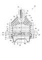
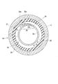
- FIG. 2 is an AA cross-sectional view of the partition member and the elastic body shown in FIG. It is sectional drawing of the partition member and elastic body which concern on 2nd Embodiment.
- the vibration isolator 10 is connected to a cylindrical first mounting member 11 connected to one of the vibration generating unit and the vibration receiving unit, and to the other of the vibration generating unit and the vibration receiving unit.
- a liquid-sealed vibration isolator including a partition member 16 partitioned into a chamber 15.
- the central axis of the first mounting member 11 is referred to as an axis O
- the direction along the axis O is referred to as an axial direction.
- the second mounting member 12 side along the axial direction is referred to as the upper side
- the partition member 16 side is referred to as the lower side.
- a direction orthogonal to the axis O is referred to as a “radial direction”
- a direction around the axis O is referred to as a “circumferential direction”.
- the first mounting member 11, the second mounting member 12, and the elastic body 13 are each formed in a circular shape or an annular shape in a plan view, and are disposed coaxially with the axis O.
- the second mounting member 12 is connected to an engine as a vibration generating unit, and the first mounting member 11 is connected to a vehicle body as a vibration receiving unit. This suppresses transmission of engine vibration to the vehicle body.
- the second mounting member 12 is a columnar member extending in the axial direction, and has a lower end formed in a hemispherical shape, and has a flange 12a above the lower end of the hemispherical shape.
- a screw hole 12b extending downward from the upper end surface of the second mounting member 12 is formed in the upper portion, and a bolt (not shown) serving as a mounting tool on the engine side is screwed into the screw hole 12b. It has become so.
- the second mounting member 12 is disposed on the upper end opening side of the first mounting member 11 via the elastic body 13.
- the elastic body 13 is a rubber body that is vulcanized and bonded to the upper end opening of the first mounting member 11 and the lower end side outer peripheral surface of the second mounting member 12, respectively, and interposed between them.
- the upper end opening of the mounting member 11 is closed from above.
- the elastic body 13 is sufficiently in close contact with the second mounting member 12 by the upper end of the elastic body 13 coming into contact with the flange portion 12 a of the second mounting member 12, so that the elastic body 13 follows better due to the displacement of the second mounting member 12. It has become.
- a rubber film 17 is integrally formed at the lower end portion of the elastic body 13 to liquid-tightly cover the inner peripheral surface of the first mounting member 11 and a part of the lower end opening edge.
- an elastic body made of synthetic resin or the like can be used in addition to rubber.
- the first mounting member 11 is formed in a cylindrical shape having a flange 18 at a lower end portion, and is connected to a vehicle body or the like as a vibration receiving portion via the flange 18. A portion of the inside of the first attachment member 11 located below the elastic body 13 is a liquid chamber 19.
- a partition member 16 is provided in the lower end portion of the first mounting member 11, and a diaphragm 20 is further provided below the partition member 16.
- the diaphragm 20 is made of an elastic material such as rubber or soft resin, and is formed in a bottomed cylindrical shape.
- the upper end portion of the diaphragm 20 is sandwiched between the partition member 16 and the ring-shaped holder 21 positioned below the partition member 16 in the axial direction.
- an annular mounting groove 16 a is formed on the lower surface of the partition member 16, in which the upper end portion of the diaphragm 20 is liquid-tightly engaged.
- a lower flange portion 22 is formed on the outer periphery of the partition member 16, and the upper surface of the holder 21 is in contact with the lower surface of the lower flange portion 22.
- the lower flange portion 22 of the partition member 16 and the holder 21 are disposed in this order at the lower end opening edge of the first mounting member 11 in this order, and are fixed by screws 23.
- the diaphragm 20 is attached to the lower end opening of the first attachment member 11 via the partition member 16.
- the diaphragm 20 has a bottom that is deep at the outer peripheral side and shallow at the center.
- various conventionally known shapes can be adopted in addition to such a shape.
- the liquid chamber 19 is formed in the first attachment member 11 by attaching the diaphragm 20 to the first attachment member 11 via the partition member 16 in this way.
- the liquid chamber 19 is disposed in the first mounting member 11, that is, inside the first mounting member 11 in plan view, and is a sealed space that is liquid-tightly sealed by the elastic body 13 and the diaphragm 20. It has become.
- the liquid chamber 19 is filled (filled) with the liquid L.
- the liquid chamber 19 is partitioned into a main liquid chamber 14 and a sub liquid chamber 15 by a partition member 16.
- the main liquid chamber 14 is formed by using the lower surface 13a of the elastic body 13 as a part of the wall surface.
- the rubber film 17 and the partition member 16 that cover the elastic body 13 and the inner peripheral surface of the first mounting member 11 in a liquid-tight manner.
- the inner volume changes due to the deformation of the elastic body 13.
- the auxiliary liquid chamber 15 is a space surrounded by the diaphragm 20 and the partition member 16, and the internal volume changes due to the deformation of the diaphragm 20.
- the vibration isolator 10 having such a configuration is a compression-type device that is mounted and used so that the main liquid chamber 14 is positioned on the upper side in the vertical direction and the auxiliary liquid chamber 15 is positioned on the lower side in the vertical direction. .
- a holding groove 16b that holds the lower end portion of the rubber film 17 in a liquid-tight manner is formed in a portion of the upper surface of the partition member 16 that is continuous with the inner peripheral edge of the lower flange portion 22.
- an annular upper flange portion 16 c whose outer peripheral surface is in liquid-tight contact with the inner peripheral surface of the rubber film 17 is formed at the upper end portion of the partition member 16. The space between the rubber film 17 and the partition member 16 is liquid-tightly closed by the holding groove 16b and the upper flange portion 16c.
- the partition member 16 is provided with a restriction passage 24 that allows the main liquid chamber 14 and the sub liquid chamber 15 to communicate with each other.
- the restriction passage 24 includes a main body flow path 25 disposed in the partition member 16, a first communication portion 26 that communicates the main body flow path 25 and the main liquid chamber 14, and a main body. And a second communication portion 27 that communicates the flow path 25 and the auxiliary liquid chamber 15.
- the main body flow path 25 extends along the circumferential direction in the partition member 16, and the flow path direction R and the circumferential direction of the main body flow path 25 are in the same direction.
- the main body flow path 25 is formed in an arc shape arranged coaxially with the axial center O, and extends over the entire circumference along the circumferential direction. Both end portions along the circumferential direction of the main body flow path 25 are separated from each other by partition walls 28a extending in the radial direction and the axial direction.
- the main body flow path 25 is defined by the first barrier 28 facing the main liquid chamber 14, the second barrier 29 facing the sub liquid chamber 15, the upper flange portion 16c, the rubber film 17, and the partition wall 28a. Has been. Note that the first barrier 28 and the second barrier 29 may not define the main body flow path 25.
- the first barrier 28 is formed in a cylindrical shape extending downward from the inner peripheral edge of the upper flange portion 16c. As shown in FIG. 2, the portion of the outer peripheral surface of the first barrier 28 where the first communication portion 26 is disposed gradually increases in the outer radial direction as the distance from the second communication portion 27 in the flow path direction R increases. Heading to For this reason, in the main body channel 25, the channel area at the connection portion 25 a with the first communication part 26 gradually decreases as the distance from the second communication part 27 in the channel direction R increases.
- the second barrier 29 is formed in a plate shape whose front and back surfaces face the axial direction. The upper surface of the second barrier 29 and the lower end of the first barrier 28 are connected to each other.
- the first barrier 28 is sandwiched between the main body flow path 25 and the main liquid chamber 14 in the radial direction, and is positioned between the main body flow path 25 and the main liquid chamber 14.
- the second barrier 29 is sandwiched between the main body flow path 25 and the secondary liquid chamber 15 in the axial direction, and is positioned between the main body flow path 25 and the secondary liquid chamber 15.
- the first communication portion 26 includes a plurality of pores 26 a that penetrate the first barrier 28 in the radial direction and are disposed along the flow path direction R.
- the plurality of pores 26 a are arranged in a portion of the first barrier 28 that forms one end portion along the circumferential direction of the main body flow path 25.
- the second communication portion 27 is an opening that penetrates the second barrier 29 in the axial direction.
- the second communication portion 27 is disposed in a portion of the second barrier 29 that forms the other end portion along the circumferential direction of the main body flow path 25.
- the plurality of pores 26a are all formed in a rectangular parallelepiped shape.
- the openings of the plurality of pores 26a toward the main liquid chamber 14 are all formed in a rectangular shape that is longer in the axial direction than in the circumferential direction when viewed from the inside in the radial direction.
- the channel cross-sectional areas of the plurality of pores 26a are the same over the entire length of the channel length of each pore 26a.
- the circumferential widths of the plurality of pores 26a are equal to each other.
- the plurality of pores 26a are arranged at equal intervals in the circumferential direction.
- the axial lengths of the plurality of pores 26a are smaller as they are spaced apart from the second communication portion 27 in the flow direction R.
- the projected area or the opening area of the minimum cross section is smaller as the plurality of pores 26a are positioned away from the second communication portion 27 in the flow path direction R.
- the ratio of the projected area or the opening area of the minimum cross section of the pore 26 a occupying per predetermined area on the inner peripheral surface facing the main liquid chamber 14 in the first barrier 28 is from the second communication portion 27.
- the plurality of pores 26a have a longer channel length as they are spaced from the second communicating portion 27 in the channel direction R. As described above, as the plurality of pores 26a are spaced apart from the second communication portion 27 in the flow direction R, the resistance when the liquid L flows through the pores 26a increases.
- the “projection area” is a narrow area passing through the center of the minimum cross section of the pore 26a to the surface of the first barrier 28 or the second barrier 29 located in the main liquid chamber 14 or the sub liquid chamber 15. The projected area in the direction in which the hole center line extends.
- the two attachment members 11 and 12 are relatively displaced while elastically deforming the elastic body 13 at the time of vibration input.
- the liquid pressure in the main liquid chamber 14 fluctuates, the liquid L in the main liquid chamber 14 flows into the sub liquid chamber 15 through the restriction passage 24, and the liquid L in the sub liquid chamber 15 flows into the restriction passage 24.
- the main liquid chamber 14 That is, a part of the liquid L in the sub liquid chamber 15 returns to the main liquid chamber 14. At this time, for example, due to the negative pressure in the main liquid chamber 14, the liquid L partially evaporates and bubbles are generated, causing cavitation collapse.
- the vibration isolator 10 when the liquid L flows from the main body flow path 25 to the main liquid chamber 14 through the plurality of pores 26a, the first barrier 28 in which these pores 26a are formed. As a result, the liquid L flows through each pore 26a while causing a pressure loss, so that an increase in the flow velocity of the liquid L flowing through each pore 26a can be suppressed. Moreover, since the liquid L circulates through the plurality of pores 26a instead of the single pore 26a, the liquid L can be branched and circulated, and the liquid L that has passed through the individual pores 26a. The flow rate of can be reduced.
- the ratio of the projected area or the opening area of the minimum cross section of each pore 26 a occupying per predetermined area on the inner peripheral surface facing the main liquid chamber 14 in the first barrier 28 is from the second communication portion 27. Since the liquid L flowing in the restriction passage 24 reaches the first communication portion 26 from the second communication portion 27, among the plurality of pores 26 a, since it gradually decreases as the distance in the flow path direction R increases. It is possible to suppress passage of the pores 26a located on the second communication portion 27 side in the flow path direction R to the first communication portion 26 side due to inertial force.
- the liquid L can easily flow out from the pores 26a located on the second communication portion 27 side, and the flow velocity of the liquid L flowing out from the respective pores 26a is made uniform to suppress local increase. In addition, it is possible to more effectively suppress the generation of air bubbles due to the generation of bubbles and the collapse of cavitation.
- the projected area or the opening area of the minimum cross section is smaller, so Among these, the ratio of the projected area or the opening area of the minimum cross section of each pore 26 a occupying per predetermined area on the inner peripheral surface facing the main liquid chamber 14 is separated from the second communication portion 27 in the flow direction R. Accordingly, a structure that gradually decreases can be reliably realized with a simple configuration.
- the flow path length is so long that the some pore 26a is located in the flow direction R from the 2nd communication part 27, the flow path length becomes long, Therefore It becomes possible to increase the pressure loss of the liquid L flowing through the pores 26a located on the first communication portion 26 side in the direction R, and among the plurality of pores 26a, the first communication portion 26 side in the flow direction R. It is possible to prevent a large amount of liquid from flowing out at high speed from the pores 26a located at the positions.
- the flow channel area at the connection portion 25a with the first communication portion 26 gradually decreases as the distance from the second communication portion 27 in the flow channel direction R decreases.
- the flow resistance gradually increases and the flow velocity of the liquid L is suppressed. This prevents the liquid L from passing through the pores 26a located on the second communication portion 27 side in the flow path direction R due to inertia, and allows the liquid to easily flow out from the pores 26a on the second communication portion 27 side.
- the circumferential interval at which the plurality of pores 26a in this embodiment are arranged is not uniform. Specifically, the interval between the pores 26a adjacent to each other in the flow path direction R gradually increases as the distance from the second communication portion increases in the flow path direction R.
- the interval between the pores 26a adjacent to each other in the flow path direction R gradually increases as the distance from the second communicating portion in the flow path direction R increases.
- the ratio of the projected area or the opening area of the minimum cross section of each pore 26 a occupying per predetermined area on the inner peripheral surface facing the main liquid chamber 14 is separated from the second communication portion 27 in the flow direction R. Accordingly, a structure that gradually decreases can be reliably realized with a simple configuration.
- the first communication portion 26 includes a plurality of pores 26a, but the present invention is not limited to this.
- the second communication portion 27 may include a plurality of pores arranged along the flow path direction R.
- the ratio of the projected area or the opening area of the minimum cross section of the pores per predetermined area of the lower surface facing the secondary liquid chamber 15 in the second barrier 29 is determined from the first communication part 26 to the flow path. As the distance in the direction R increases, the distance may gradually decrease.
- the plurality of pores in this case may penetrate the second barrier 29 in the axial direction.
- the projected area or the opening area of the minimum cross section may be smaller as the plurality of fine pores are spaced apart from the first communication portion 26 in the flow path direction R.
- the plurality of pores in this case may have a longer channel length as they are positioned away from the first communication portion 26 in the channel direction R.
- the interval between the pores adjacent to each other in the flow path direction R may gradually increase as the distance from the first communication portion increases in the flow path direction R.
- the plurality of pores 26 a may not be formed in the first communication portion 26.
- the flow passage area in the connection portion 25a with the first communication portion 26 in the main body flow passage 25 gradually decreases as the flow passage direction R is separated from the second communication portion 27.
- the flow area at the connection portion with the second communication portion 27 may gradually decrease as the distance from the first communication portion 26 in the flow direction R is increased.
- the axial width of the main flow channel 25 in the connection portion 25a for example.
- the partition member 16 may be formed so as to gradually decrease as the distance from the second communication portion 27 increases in the flow path direction R.
- the pore 26a was formed in the rectangular shape in the said embodiment, you may form in a column shape or a cone shape.
- the channel cross-sectional area of the pores 26a is the same over the entire length of the channel length, but the pores 26a whose channel cross-sectional area changes may be adopted.
- the plurality of pores 26a are arranged along the flow path direction R.
- the plurality of pores 26a may be arranged along the flow path direction R and along the axial direction. .
- the main body flow path 25 is extended and arrange
- the partition member 16 is disposed at the lower end portion of the first mounting member 11, and the lower flange portion 22 of the partition member 16 is brought into contact with the lower end surface of the first mounting member 11.
- the partition member 16 is disposed sufficiently above the lower end surface of the first mounting member 11, and the diaphragm 20 is disposed on the lower side of the partition member 16, that is, the lower end portion of the first mounting member 11.
- the secondary liquid chamber 15 may be formed from the lower end of the member 11 to the bottom surface of the diaphragm 20.
- the main liquid chamber 14 is located in the vertical lower side, and The auxiliary liquid chamber 15 is mounted so as to be positioned on the upper side in the vertical direction, and can be applied to a suspension type vibration isolator in which a negative pressure is applied to the main liquid chamber 14 when a support load is applied.
- the partition member 16 partitions the liquid chamber 19 in the first mounting member 11 into the main liquid chamber 14 having the elastic body 13 as a part of the wall surface and the sub liquid chamber 15. It is not limited to this.
- a pair of elastic bodies 13 may be provided in the axial direction, and instead of providing the auxiliary liquid chamber 15, a pressure receiving liquid chamber having the elastic body 13 at a part of the wall surface may be provided.
- the partition member 16 partitions the liquid chamber 19 in the first mounting member 11 in which the liquid L is enclosed into the first liquid chamber 14 and the second liquid chamber 15, and the first liquid chamber 14 and the second liquid chamber 15. At least one of the two liquid chambers can be appropriately changed to another configuration having the elastic body 13 in a part of the wall surface.
- the vibration isolator 10 according to the present invention is not limited to the engine mount of the vehicle, and can be applied to other than the engine mount.
- the present invention can be applied to a mount of a generator mounted on a construction machine, or can be applied to a mount of a machine installed in a factory or the like.
- the two attachment members are relatively displaced while elastically deforming the elastic body, the liquid pressure in the first liquid chamber is fluctuated, and the liquid passes through the restriction passage. An attempt is made to circulate between the first liquid chamber and the second liquid chamber. At this time, the liquid flows into the main body flow path through one of the first communication section and the second communication section, and then flows out from the main flow path through the other of the first communication section and the second communication section.
- the flow rate difference between the liquid that has passed through the pores and flowed into the first liquid chamber or the second liquid chamber and the liquid in the first liquid chamber or the second liquid chamber is suppressed to a small value. It is possible to suppress the generation of vortices caused and the generation of bubbles due to the vortices. Furthermore, the ratio of the projected area or the opening area of the minimum cross section of each pore per predetermined area in the first barrier or the second barrier flows from either one of the first communication portion and the second communication portion. Since the liquid gradually decreases as the distance in the road direction increases, when the liquid flowing in the restriction passage reaches one of the first communication portion and the second communication portion, the flow of the plurality of pores is reduced.
- the projected area or the opening area of the minimum cross section is such that the plurality of fine pores are located away from either one of the first communication portion and the second communication portion in the flow path direction. May be smaller.
- the ratio of the projected area or the opening area of the minimum cross section of each pore occupying per predetermined area in the first barrier or the second barrier is from either one of the first communication part and the second communication part.
- the interval between the pores adjacent to each other in the flow channel direction gradually increases as the distance from the other of the first communication portion and the second communication portion increases in the flow channel direction. Also good.
- the ratio of the projected area or the opening area of the minimum cross section of each pore occupying per predetermined area in the first barrier or the second barrier is from either one of the first communication part and the second communication part.
- the present invention it is possible to provide a vibration isolator that can suppress the occurrence of abnormal noise due to cavitation collapse without reducing the vibration isolation characteristics with a simple structure.
- vibration isolator 11 first mounting member 12 second mounting member 13 elastic body 14 main liquid chamber (first liquid chamber) 15 Secondary liquid chamber (second liquid chamber) 16 Partition member 19 Liquid chamber 24 Restriction passage 25 Main body flow path 25a Connection portion 26 First communication portion 27 Second communication portion 28 First barrier 29 Second barrier 31 First opening (opening) L liquid
Landscapes
- Engineering & Computer Science (AREA)
- General Engineering & Computer Science (AREA)
- Mechanical Engineering (AREA)
- Combined Devices Of Dampers And Springs (AREA)
Priority Applications (3)
| Application Number | Priority Date | Filing Date | Title |
|---|---|---|---|
| EP17815291.4A EP3477148B1 (de) | 2016-06-23 | 2017-06-16 | Vibrationsdämpfungsvorrichtung |
| CN201780038196.5A CN109312811B (zh) | 2016-06-23 | 2017-06-16 | 防振装置 |
| US16/099,572 US10788093B2 (en) | 2016-06-23 | 2017-06-16 | Vibration-damping device |
Applications Claiming Priority (2)
| Application Number | Priority Date | Filing Date | Title |
|---|---|---|---|
| JP2016124914A JP6674334B2 (ja) | 2016-06-23 | 2016-06-23 | 防振装置 |
| JP2016-124914 | 2016-06-23 |
Publications (1)
| Publication Number | Publication Date |
|---|---|
| WO2017221823A1 true WO2017221823A1 (ja) | 2017-12-28 |
Family
ID=60784532
Family Applications (1)
| Application Number | Title | Priority Date | Filing Date |
|---|---|---|---|
| PCT/JP2017/022266 Ceased WO2017221823A1 (ja) | 2016-06-23 | 2017-06-16 | 防振装置 |
Country Status (5)
| Country | Link |
|---|---|
| US (1) | US10788093B2 (de) |
| EP (1) | EP3477148B1 (de) |
| JP (1) | JP6674334B2 (de) |
| CN (1) | CN109312811B (de) |
| WO (1) | WO2017221823A1 (de) |
Families Citing this family (4)
| Publication number | Priority date | Publication date | Assignee | Title |
|---|---|---|---|---|
| JP6577911B2 (ja) | 2016-06-23 | 2019-09-18 | 株式会社ブリヂストン | 防振装置 |
| JP6824818B2 (ja) * | 2017-05-18 | 2021-02-03 | 株式会社ブリヂストン | 防振装置 |
| JP6983060B2 (ja) | 2017-12-26 | 2021-12-17 | 株式会社ブリヂストン | 防振装置 |
| JP7290549B2 (ja) * | 2019-11-07 | 2023-06-13 | 株式会社プロスパイラ | 防振装置 |
Citations (5)
| Publication number | Priority date | Publication date | Assignee | Title |
|---|---|---|---|---|
| JPS62224749A (ja) * | 1986-03-13 | 1987-10-02 | ロ−ド・コ−ポレ−シヨン | 流体充てん振動絶縁装置 |
| JP2007182930A (ja) * | 2006-01-06 | 2007-07-19 | Toyo Tire & Rubber Co Ltd | 液封入式防振装置 |
| JP2012172832A (ja) | 2011-02-24 | 2012-09-10 | Toyo Tire & Rubber Co Ltd | 液封入式防振装置 |
| WO2016027606A1 (ja) * | 2014-08-20 | 2016-02-25 | 株式会社ブリヂストン | 防振装置 |
| JP2016124914A (ja) | 2014-12-26 | 2016-07-11 | 太陽インキ製造株式会社 | 硬化性樹脂組成物、ドライフィルム、硬化物およびプリント配線板 |
Family Cites Families (7)
| Publication number | Priority date | Publication date | Assignee | Title |
|---|---|---|---|---|
| DE3225700C1 (de) * | 1982-07-09 | 1983-11-17 | Fa. Carl Freudenberg, 6940 Weinheim | Elastisches Gummilager |
| JPS6040843A (ja) * | 1983-08-15 | 1985-03-04 | Bridgestone Corp | 防振装置用オリフイス構造 |
| JPH083344B2 (ja) * | 1988-02-29 | 1996-01-17 | 日産自動車株式会社 | 粘度可変流体封入制御型防振体 |
| EP0756102B1 (de) * | 1995-07-27 | 1999-10-27 | Lemförder Metallwaren AG | Motorlager für Kraftfahrzeuge |
| CN101896733B (zh) | 2007-12-12 | 2013-12-18 | 株式会社普利司通 | 防振装置 |
| JP5919129B2 (ja) | 2012-08-03 | 2016-05-18 | 株式会社ブリヂストン | 防振装置 |
| EP3184850B1 (de) * | 2014-08-20 | 2019-01-23 | Bridgestone Corporation | Schwingungsdämpfungsvorrichtung |
-
2016
- 2016-06-23 JP JP2016124914A patent/JP6674334B2/ja active Active
-
2017
- 2017-06-16 WO PCT/JP2017/022266 patent/WO2017221823A1/ja not_active Ceased
- 2017-06-16 US US16/099,572 patent/US10788093B2/en active Active
- 2017-06-16 EP EP17815291.4A patent/EP3477148B1/de active Active
- 2017-06-16 CN CN201780038196.5A patent/CN109312811B/zh active Active
Patent Citations (5)
| Publication number | Priority date | Publication date | Assignee | Title |
|---|---|---|---|---|
| JPS62224749A (ja) * | 1986-03-13 | 1987-10-02 | ロ−ド・コ−ポレ−シヨン | 流体充てん振動絶縁装置 |
| JP2007182930A (ja) * | 2006-01-06 | 2007-07-19 | Toyo Tire & Rubber Co Ltd | 液封入式防振装置 |
| JP2012172832A (ja) | 2011-02-24 | 2012-09-10 | Toyo Tire & Rubber Co Ltd | 液封入式防振装置 |
| WO2016027606A1 (ja) * | 2014-08-20 | 2016-02-25 | 株式会社ブリヂストン | 防振装置 |
| JP2016124914A (ja) | 2014-12-26 | 2016-07-11 | 太陽インキ製造株式会社 | 硬化性樹脂組成物、ドライフィルム、硬化物およびプリント配線板 |
Also Published As
| Publication number | Publication date |
|---|---|
| JP2017227294A (ja) | 2017-12-28 |
| JP6674334B2 (ja) | 2020-04-01 |
| US20190145488A1 (en) | 2019-05-16 |
| EP3477148B1 (de) | 2020-06-24 |
| US10788093B2 (en) | 2020-09-29 |
| EP3477148A4 (de) | 2019-06-26 |
| CN109312811B (zh) | 2020-09-18 |
| EP3477148A1 (de) | 2019-05-01 |
| CN109312811A (zh) | 2019-02-05 |
Similar Documents
| Publication | Publication Date | Title |
|---|---|---|
| JP6450619B2 (ja) | 防振装置 | |
| JP6265562B2 (ja) | 防振装置 | |
| WO2018198444A1 (ja) | 防振装置 | |
| WO2017222014A1 (ja) | 防振装置 | |
| WO2017221823A1 (ja) | 防振装置 | |
| JP6619702B2 (ja) | 防振装置 | |
| EP3617546B1 (de) | Vibrationsdämpfungsvorrichtung | |
| WO2018225289A1 (ja) | 防振装置 | |
| JP6577911B2 (ja) | 防振装置 | |
| WO2018211754A1 (ja) | 防振装置 | |
| WO2018193895A1 (ja) | 防振装置 | |
| JP2018194101A (ja) | 防振装置 | |
| JP2018119621A (ja) | 防振装置 | |
| JP2018115713A (ja) | 防振装置 | |
| JP7161842B2 (ja) | 防振装置 | |
| JP2019105281A (ja) | 防振装置 | |
| JP2019203542A (ja) | 防振装置 |
Legal Events
| Date | Code | Title | Description |
|---|---|---|---|
| 121 | Ep: the epo has been informed by wipo that ep was designated in this application |
Ref document number: 17815291 Country of ref document: EP Kind code of ref document: A1 |
|
| NENP | Non-entry into the national phase |
Ref country code: DE |
|
| ENP | Entry into the national phase |
Ref document number: 2017815291 Country of ref document: EP Effective date: 20190123 |