WO2017222007A1 - Filtre de ligne composite - Google Patents
Filtre de ligne composite Download PDFInfo
- Publication number
- WO2017222007A1 WO2017222007A1 PCT/JP2017/022979 JP2017022979W WO2017222007A1 WO 2017222007 A1 WO2017222007 A1 WO 2017222007A1 JP 2017022979 W JP2017022979 W JP 2017022979W WO 2017222007 A1 WO2017222007 A1 WO 2017222007A1
- Authority
- WO
- WIPO (PCT)
- Prior art keywords
- magnetic path
- line filter
- path portion
- composite line
- core
- Prior art date
- Legal status (The legal status is an assumption and is not a legal conclusion. Google has not performed a legal analysis and makes no representation as to the accuracy of the status listed.)
- Ceased
Links
Images







Classifications
-
- H—ELECTRICITY
- H01—ELECTRIC ELEMENTS
- H01F—MAGNETS; INDUCTANCES; TRANSFORMERS; SELECTION OF MATERIALS FOR THEIR MAGNETIC PROPERTIES
- H01F27/00—Details of transformers or inductances, in general
- H01F27/28—Coils; Windings; Conductive connections
- H01F27/30—Fastening or clamping coils, windings, or parts thereof together; Fastening or mounting coils or windings on core, casing, or other support
-
- H—ELECTRICITY
- H01—ELECTRIC ELEMENTS
- H01F—MAGNETS; INDUCTANCES; TRANSFORMERS; SELECTION OF MATERIALS FOR THEIR MAGNETIC PROPERTIES
- H01F3/00—Cores, Yokes, or armatures
- H01F3/10—Composite arrangements of magnetic circuits
- H01F3/12—Magnetic shunt paths
-
- H—ELECTRICITY
- H01—ELECTRIC ELEMENTS
- H01F—MAGNETS; INDUCTANCES; TRANSFORMERS; SELECTION OF MATERIALS FOR THEIR MAGNETIC PROPERTIES
- H01F41/00—Apparatus or processes specially adapted for manufacturing or assembling magnets, inductances or transformers; Apparatus or processes specially adapted for manufacturing materials characterised by their magnetic properties
- H01F41/02—Apparatus or processes specially adapted for manufacturing or assembling magnets, inductances or transformers; Apparatus or processes specially adapted for manufacturing materials characterised by their magnetic properties for manufacturing cores, coils, or magnets
- H01F41/04—Apparatus or processes specially adapted for manufacturing or assembling magnets, inductances or transformers; Apparatus or processes specially adapted for manufacturing materials characterised by their magnetic properties for manufacturing cores, coils, or magnets for manufacturing coils
- H01F41/06—Coil winding
-
- H—ELECTRICITY
- H01—ELECTRIC ELEMENTS
- H01F—MAGNETS; INDUCTANCES; TRANSFORMERS; SELECTION OF MATERIALS FOR THEIR MAGNETIC PROPERTIES
- H01F17/00—Fixed inductances of the signal type
- H01F17/04—Fixed inductances of the signal type with magnetic core
-
- H—ELECTRICITY
- H01—ELECTRIC ELEMENTS
- H01F—MAGNETS; INDUCTANCES; TRANSFORMERS; SELECTION OF MATERIALS FOR THEIR MAGNETIC PROPERTIES
- H01F17/00—Fixed inductances of the signal type
- H01F17/04—Fixed inductances of the signal type with magnetic core
- H01F17/06—Fixed inductances of the signal type with magnetic core with core substantially closed in itself, e.g. toroid
-
- H—ELECTRICITY
- H01—ELECTRIC ELEMENTS
- H01F—MAGNETS; INDUCTANCES; TRANSFORMERS; SELECTION OF MATERIALS FOR THEIR MAGNETIC PROPERTIES
- H01F27/00—Details of transformers or inductances, in general
- H01F27/06—Mounting, supporting, or suspending transformers, reactors, or choke coils not being of the signal type
-
- H—ELECTRICITY
- H01—ELECTRIC ELEMENTS
- H01F—MAGNETS; INDUCTANCES; TRANSFORMERS; SELECTION OF MATERIALS FOR THEIR MAGNETIC PROPERTIES
- H01F27/00—Details of transformers or inductances, in general
- H01F27/28—Coils; Windings; Conductive connections
-
- H—ELECTRICITY
- H01—ELECTRIC ELEMENTS
- H01F—MAGNETS; INDUCTANCES; TRANSFORMERS; SELECTION OF MATERIALS FOR THEIR MAGNETIC PROPERTIES
- H01F27/00—Details of transformers or inductances, in general
- H01F27/28—Coils; Windings; Conductive connections
- H01F27/32—Insulating of coils, windings, or parts thereof
-
- H—ELECTRICITY
- H01—ELECTRIC ELEMENTS
- H01F—MAGNETS; INDUCTANCES; TRANSFORMERS; SELECTION OF MATERIALS FOR THEIR MAGNETIC PROPERTIES
- H01F27/00—Details of transformers or inductances, in general
- H01F27/28—Coils; Windings; Conductive connections
- H01F27/32—Insulating of coils, windings, or parts thereof
- H01F27/324—Insulation between coil and core, between different winding sections, around the coil; Other insulation structures
-
- H—ELECTRICITY
- H01—ELECTRIC ELEMENTS
- H01F—MAGNETS; INDUCTANCES; TRANSFORMERS; SELECTION OF MATERIALS FOR THEIR MAGNETIC PROPERTIES
- H01F27/00—Details of transformers or inductances, in general
- H01F27/28—Coils; Windings; Conductive connections
- H01F27/32—Insulating of coils, windings, or parts thereof
- H01F27/324—Insulation between coil and core, between different winding sections, around the coil; Other insulation structures
- H01F27/325—Coil bobbins
-
- H—ELECTRICITY
- H01—ELECTRIC ELEMENTS
- H01F—MAGNETS; INDUCTANCES; TRANSFORMERS; SELECTION OF MATERIALS FOR THEIR MAGNETIC PROPERTIES
- H01F37/00—Fixed inductances not covered by group H01F17/00
-
- H—ELECTRICITY
- H01—ELECTRIC ELEMENTS
- H01F—MAGNETS; INDUCTANCES; TRANSFORMERS; SELECTION OF MATERIALS FOR THEIR MAGNETIC PROPERTIES
- H01F41/00—Apparatus or processes specially adapted for manufacturing or assembling magnets, inductances or transformers; Apparatus or processes specially adapted for manufacturing materials characterised by their magnetic properties
- H01F41/02—Apparatus or processes specially adapted for manufacturing or assembling magnets, inductances or transformers; Apparatus or processes specially adapted for manufacturing materials characterised by their magnetic properties for manufacturing cores, coils, or magnets
- H01F41/04—Apparatus or processes specially adapted for manufacturing or assembling magnets, inductances or transformers; Apparatus or processes specially adapted for manufacturing materials characterised by their magnetic properties for manufacturing cores, coils, or magnets for manufacturing coils
- H01F41/06—Coil winding
- H01F41/08—Winding conductors onto closed formers or cores, e.g. threading conductors through toroidal cores
-
- H—ELECTRICITY
- H01—ELECTRIC ELEMENTS
- H01F—MAGNETS; INDUCTANCES; TRANSFORMERS; SELECTION OF MATERIALS FOR THEIR MAGNETIC PROPERTIES
- H01F27/00—Details of transformers or inductances, in general
- H01F27/28—Coils; Windings; Conductive connections
- H01F27/29—Terminals; Tapping arrangements for signal inductances
- H01F2027/297—Terminals; Tapping arrangements for signal inductances with pin-like terminal to be inserted in hole of printed path
-
- Y—GENERAL TAGGING OF NEW TECHNOLOGICAL DEVELOPMENTS; GENERAL TAGGING OF CROSS-SECTIONAL TECHNOLOGIES SPANNING OVER SEVERAL SECTIONS OF THE IPC; TECHNICAL SUBJECTS COVERED BY FORMER USPC CROSS-REFERENCE ART COLLECTIONS [XRACs] AND DIGESTS
- Y02—TECHNOLOGIES OR APPLICATIONS FOR MITIGATION OR ADAPTATION AGAINST CLIMATE CHANGE
- Y02T—CLIMATE CHANGE MITIGATION TECHNOLOGIES RELATED TO TRANSPORTATION
- Y02T10/00—Road transport of goods or passengers
- Y02T10/60—Other road transportation technologies with climate change mitigation effect
- Y02T10/70—Energy storage systems for electromobility, e.g. batteries
-
- Y—GENERAL TAGGING OF NEW TECHNOLOGICAL DEVELOPMENTS; GENERAL TAGGING OF CROSS-SECTIONAL TECHNOLOGIES SPANNING OVER SEVERAL SECTIONS OF THE IPC; TECHNICAL SUBJECTS COVERED BY FORMER USPC CROSS-REFERENCE ART COLLECTIONS [XRACs] AND DIGESTS
- Y02—TECHNOLOGIES OR APPLICATIONS FOR MITIGATION OR ADAPTATION AGAINST CLIMATE CHANGE
- Y02T—CLIMATE CHANGE MITIGATION TECHNOLOGIES RELATED TO TRANSPORTATION
- Y02T10/00—Road transport of goods or passengers
- Y02T10/60—Other road transportation technologies with climate change mitigation effect
- Y02T10/7072—Electromobility specific charging systems or methods for batteries, ultracapacitors, supercapacitors or double-layer capacitors
-
- Y—GENERAL TAGGING OF NEW TECHNOLOGICAL DEVELOPMENTS; GENERAL TAGGING OF CROSS-SECTIONAL TECHNOLOGIES SPANNING OVER SEVERAL SECTIONS OF THE IPC; TECHNICAL SUBJECTS COVERED BY FORMER USPC CROSS-REFERENCE ART COLLECTIONS [XRACs] AND DIGESTS
- Y02—TECHNOLOGIES OR APPLICATIONS FOR MITIGATION OR ADAPTATION AGAINST CLIMATE CHANGE
- Y02T—CLIMATE CHANGE MITIGATION TECHNOLOGIES RELATED TO TRANSPORTATION
- Y02T90/00—Enabling technologies or technologies with a potential or indirect contribution to GHG emissions mitigation
- Y02T90/10—Technologies relating to charging of electric vehicles
- Y02T90/14—Plug-in electric vehicles
Definitions
- the present invention relates to a composite line filter, and more particularly to a composite line filter having a bobbin provided with a gear.
- the line filter described in Patent Document 1 has a bobbin, a closed magnetic path magnetic core, a center magnetic core, and a terminal block.
- the bobbin is formed of a two-divided winding frame and is attached to the central magnetic leg of the closed magnetic circuit core.
- the bobbin also has two outer collars and a middle collar located between them.
- a gear is provided on one of the outer flanges, and by applying an external force to the gear, the bobbin can be rotated about the central magnetic leg.
- the winding is wound around the bobbin using this rotation.
- Two windings are respectively disposed between each of the two outer flange portions and the middle flange portion.
- the center magnetic core is inserted into a through guide hole provided in the middle collar portion.
- the line filter of Patent Document 1 functions as a composite line filter corresponding to both the common mode and the normal mode by having a center magnetic core.
- the gear of the line filter described in Patent Document 1 is provided on the outer side in the axial direction of the outer flange portion, which contributes to hindering the downsizing of the line filter.
- An object of the present invention is to provide a composite line filter with reduced axial dimensions.
- One aspect of the present invention is a composite line filter having a bobbin, two coils, and a magnetic core, the coils being wound around the bobbin in a state of being separated from each other in the axial direction.
- the magnetic core includes a closed magnetic path portion and a sub magnetic path portion, the bobbin is attached to the closed magnetic path portion, and the sub magnetic path portion is connected to the shaft from the closed magnetic path portion.
- the bobbin Extending in a direction intersecting the direction and positioned between the coils in the axial direction, the bobbin has a gear, and the gear is positioned between the coils in the axial direction.
- a composite line filter is provided.
- the bobbin gear is positioned between the coils wound around the bobbin in the axial direction.
- the partition plates provided on both sides of the sub magnetic path portion are also positioned between the coils in the axial direction. When viewed in a direction perpendicular to the axial direction, the gear overlaps at least partially with the partition plate. This eliminates the need for a dedicated gear space in the axial direction and reduces the axial dimension of the composite line filter.
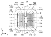
- FIG. 1 is a perspective view showing a composite line filter according to a first embodiment of the present invention. It is a top view which shows the composite line filter of FIG.
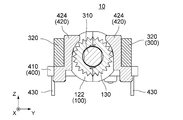
- FIG. 3 is a sectional view showing the composite line filter of FIG. 2 along the line AA. However, the coil is omitted.
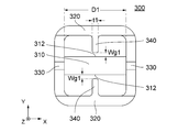
- It is a top view which shows the magnetic core of FIG.
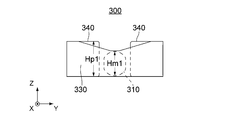
- It is a right view which shows the magnetic core of FIG.
- a part of the protrusion that is not visible and the middle leg are indicated by broken lines.
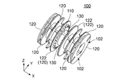
- It is a perspective view which shows the bobbin contained in the composite line filter of FIG.
- FIG. 1 It is a top view which shows the magnetic core of FIG. It is a right view which shows the magnetic core of FIG. A part of the protrusion that is not visible and the middle leg are indicated by broken lines. It is a perspective view which shows the terminal block contained in the composite line filter of FIG.
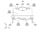
- the composite line filter 10 includes a bobbin 100, two coils 210 and 220, a magnetic core 300, and a terminal block 400. ing.
- the coils 210 and 220 are wound around the bobbin 100. Specifically, the coils 210 and 220 are wound around the bobbin 100 while being separated from each other in the axial direction.
- the bobbin 100 is attached to a part of the closed magnetic path portion of the magnetic core 300, and the magnetic core 300 is attached to the terminal block 400.
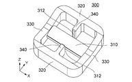
- the magnetic core 300 includes a middle leg (core part) 310, two outer legs 320, two connecting parts 330, and two projecting parts 340. Yes.
- the middle leg 310, the outer leg 320, the connecting portion 330, and the protruding portion 340 are integrally formed.
- the present invention is not limited to this, and the magnetic core 300 may be configured by joining a plurality of components.
- the magnetic core 300 formed integrally it is possible to reduce the number of parts and the number of assembly steps, and to avoid quality deterioration depending on the assembly accuracy.
- the middle leg 310 has a substantially cylindrical shape (see FIGS. 3 and 8) and extends in the first direction (X direction, axial direction).
- the outer leg 320 has a flat quadrangular prism shape except for both ends, and is arranged in parallel with the middle leg 310 and extends in the X direction.
- the outer leg 320 and the middle leg 310 are separated from each other by a predetermined distance in a direction orthogonal to the X direction (Y direction).
- the connecting portion 330 has a quadrangular prism shape with a narrowed central portion, and extends in the Y direction. In other words, as shown in FIG. 8, the connecting portion 330 has a shape in which the height of both end portions is the highest in the Y direction and gradually decreases toward the center portion.
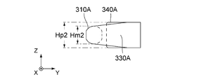
- the height Hp1 of the protrusion 340 is higher than the height Hm1 of the middle leg 310.
- the height direction is the Z direction (second direction) orthogonal to both the X direction (first direction) and the Y direction (direction parallel to the protruding direction of the protrusion 340). Therefore, it can be said that the dimension (height Hp1) of the protrusion 340 in the second direction is longer than the dimension (height Hm1) of the middle leg 310 in the second direction.
- the dimension of the sub magnetic path part (projection part 340) is longer than the dimension of the core part (middle leg 310) in the second direction orthogonal to both the protruding direction and the first direction. .
- the cross-sectional area of the sub magnetic path portion is increased, magnetic saturation is less likely, and a desired normal mode inductance can be obtained.
- the connecting portion 330 connects the two outer legs 320 and both ends of the middle leg 310, respectively.
- one connecting portion 330 connects one end of each outer leg 320 and one end of the middle leg 310
- the other connecting portion 330 connects to the other end of each outer leg 320.
- the other end of the middle leg 310 is connected.
- the connecting portion 330 and the outer leg 320 are continuous with each other to form a main magnetic path portion that connects both ends of the middle leg 310 with two paths.
- Each outer leg 320 forms a closed magnetic path part together with the middle leg 310 and a part of the connecting part 330.
- the shape of the magnetic core 300 in which the middle leg 310, the outer leg 320, and the coupling portion 330 are coupled as described above is an angular 8-shape when viewed along the Z direction.
- the protrusion 340 protrudes from the center of the outer leg 320 in the X direction in a direction intersecting the X direction.
- the projection 340 protrudes from the outer leg 320 toward the middle leg 310 along the Y direction.
- the two protrusions 340 protruding from the two outer legs 320 protrude in directions facing each other (+ Y direction and ⁇ Y direction).
- the protruding portion 340 protrudes from the outer leg 320 toward the middle leg 310 to form a sub magnetic path portion.
- the sub magnetic path portion extends from a part of the closed magnetic path portion in a direction crossing the axial direction (X direction).
- the sub magnetic path part is located between the coils 210 and 220 in the axial direction.
- the middle leg 310 has a facing portion 312 that faces the tip of each projection 340.
- a predetermined gap (gap) is provided between the tip of the protrusion 340 and the facing portion 312 of the middle leg 310.
- the portion of each outer leg 320 in the X direction that is opposite to the middle leg 310 is the first portion of the closed magnetic path portion.
- the central portion of the middle leg 310 in the X direction and the portion facing each outer leg 320 is the second portion of the closed magnetic path portion.
- the first portion of the closed magnetic path portion is located between one ends of the coils 210 and 220, and the second portion of the closed magnetic path portion is between the other ends of the coils 210 and 220. Is located.
- the sub magnetic path portion protrudes from the first portion toward the second portion.
- the auxiliary magnetic path portion is located between the coils 210 and 220 in the axial direction, and extends in the axial direction from one part of the winding core portion and the main magnetic path portion toward the remaining one facing portion. What is necessary is just to protrude in the direction which crosses.
- the sub-magnetic path part may be located between the first part and the second part and protrude from at least one of the first part and the second part toward the other.
- the protrusion 340 has a thickness t1.
- the thickness t ⁇ b> 1 of the protrusion 340 is a dimension in a direction (X direction) parallel to the plane including the axes of the coils 210 and 220 and perpendicular to the protruding direction.
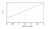
- the thickness t1 of the protrusion 340 is set to 0.5 mm or more. In other words, the lower limit of the thickness t1 of the protrusion 340 is 0.5 mm. As can be understood from FIG.
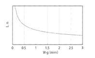
- the thickness t1 of the protrusion 340 and the normal mode inductance Ln in the normal mode are in a proportional relationship, and when the thickness t1 is less than 0.5 mm, the necessary normal mode inductance Ln is obtained. Because it disappears. This is because the induction coefficient AL of the magnetic core 300 decreases as the thickness t1 of the protrusion 340 decreases. Although it is conceivable to increase the normal mode inductance Ln by increasing the number of turns of the coils 210 and 220 with respect to the reduction of the induction coefficient AL, in that case, the resistance Rdc increases. Further, when the thickness t1 of the protrusion 340 decreases, magnetic saturation is likely to occur.
- the thickness t1 of the protrusion 340 is set to D1 / 2 mm or less.
- the upper limit of the thickness t1 of the protrusion 340 is D1 / 2 mm.
- D1 is an inner method of the closed magnetic path portion in the X direction orthogonal to the protruding direction of the protruding portion 340, as shown in FIG.
- an increase in the thickness t1 of the protrusion 340 means a decrease in a space in which the coils 210 and 220 can be wound, that is, a decrease in the number N of turns of the coils 210 and 220.
- the thickness t1 of the protrusion 340 needs to be D1 / 2 mm or less.
- the present invention is not limited to this.
- the inner diameter may be used instead of the inner method of the closed magnetic circuit. That is, in the present invention, the upper limit of the dimension of the sub magnetic path portion in the first direction may be D / 2 mm, where Dmm is the inner method or inner diameter of the closed magnetic path portion in the first direction.
- the thickness t1 of the protrusion 340 may be 3.0 mm or less.
- the distance (gap width) Wg1 (see FIG. 7) between the protruding portion 340 and the facing portion 312 does not include 0, and the root (first portion) of the facing portion 312 and the protruding portion 340 is not included. ) Is shorter than the distance to.
- the gap width Wg1 is set according to the magnetic core material and desired normal mode characteristics.
- the gap width Wg1 can be set to 0.1 mm or more and 2.0 mm or less. In this case, the lower limit of the gap width Wg1 is 0.1 mm, and the upper limit is 2.0 mm.
- the lower limit of the distance between the sub magnetic path part (projection part 340) and the opposing part (middle leg 310) can be 0.1 mm, and the upper limit can be 2.0 mm.
- the gap width Wg1 is limited for the following reason. That is, if the gap width Wg1 decreases, the leakage flux increases and causes magnetic saturation, so that the direct current superimposition characteristics deteriorate. Further, as understood from FIG. 12, if the gap width Wg1 becomes too large, the necessary normal mode inductance Ln cannot be obtained.
- the auxiliary magnetic path part is configured to protrude from the first part and the second part of the closed magnetic path (the middle leg 310 and the outer leg 320). Therefore, it is possible to suppress variation in dimensions and to suppress variation in characteristics as compared with the case where two parts are combined. In addition, since variation in dimensions is suppressed, it is easy to fit the thickness t1 of the protrusion 340 and the gap width Wg1 within predetermined ranges. Furthermore, since the thickness t1 and the gap width Wg1 of the protrusion 340 can be kept within predetermined ranges, the characteristics including the normal mode inductance Ln can be improved.
- the protrusion 340 protrudes from the outer leg 320 toward the middle leg 310, but the protrusion 340 may be formed to protrude from the middle leg 310 toward the outer leg 320.
- the protrusion dimension of the protrusion 340 is increased when the protrusion 340 is provided on the outer leg 320. There is an advantage that you can.
- the protrusion 340 is provided on the middle leg 310, the bobbin 100 cannot be rotated unless the bobbin 100 is divided into two in the axial direction, which causes an increase in the number of parts.
- the bobbin 100 has a cylindrical portion 110, a plurality of flange portions 120, and two gears 130.
- the cylindrical portion 110 has a central axis extending in the first direction (X direction, axial direction).
- the axis of the coil 210 coincides with the central axis of the cylindrical portion 110.
- the flange portion 120 extends outward from the outer peripheral surface of the cylindrical portion 110 in the radial direction orthogonal to the central axis.
- the notch 120 is formed with several notches depending on the purpose. As can be understood from FIGS.
- the six flange portions 120 closer to the center in the X direction define the positions of the coils 210 and 220 wound around the cylindrical portion 110 in the X direction.
- the two flanges 120 located on the innermost side in the X direction, that is, the inner flange 122 defines a distance between the coils 210 and 220 in the X direction.
- the two gears 130 are formed on the surfaces of the inner flange 122 facing each other. In other words, the gear 130 is located between the inner flanges 122 in the X direction.
- the two gears 130 have the same shape and are arranged to be mirror-symmetric with respect to a plane perpendicular to the X axis.
- the gear 130 is positioned between the coils 210 and 220 in a state where the coils 210 and 220 are wound around the bobbin 100.
- the bobbin 100 includes two reel parts 102.
- Each reel component 102 is substantially equivalent to a bobbin 100 divided into two planes including a central axis.
- the two reel components 102 may be formed in the same shape or may include different shape portions.
- each reel component 102 includes a part of a half-pipe cylindrical portion 110.
- the bobbin 100 is attached to the middle leg 310 of the magnetic core 300 by combining the reel part 102 so as to sandwich the middle leg 310 of the magnetic core 300 between the two reel parts 102 and fixing them together.
- the bobbin 100 can rotate around the middle leg 310 while being attached to the middle leg 310.
- the terminal block 400 includes a base 410, two pairs of wall portions 420, and two pairs of pins 430 (see FIG. 4).
- Each wall part 420 has a main part 422 and a partition plate 424.
- partition plate 424 is a part of terminal block 400.
- the base 410 has a generally rectangular frame shape.
- the wall portion 420 is provided along two inner edges facing each other in the Y direction of the base portion 410 and protrudes upward (+ Z direction) from the base portion 410.
- the main portion 422 of the wall portion 420 is formed along the inner edge of the base portion 410.
- the main portions 422 of the paired wall portions 420 are formed at inner edges of the different base portions 410 and face each other in the Y direction.
- the main portions 422 arranged in the X direction belong to different pairs of wall portions 420.
- the main parts 422 arranged in the X direction are separated from each other by a predetermined distance.
- the partition plate 424 is provided at each inner end portion in the X direction of the two main portions 422 arranged in the X direction.
- the partition plates 424 of the pair of wall portions 420 protrude along the Y direction so as to face each other.
- the base part 410 and the wall part 420 can be integrally molded using resin.
- the pins 430 are provided in the vicinity of the four corners of the base 410 and protrude downward ( ⁇ Z direction) from the base 410.
- the paired pins 430 are arranged in the Y direction.
- the pin 430 is made of metal, and can be integrally formed with the base portion 410 and the wall portion 420 by insert molding. As shown in FIG. 4, end portions of windings constituting the coils 210 and 220 are wound around and connected to the pin 430. The ends of the windings of the coils 210 and 220 are connected to a pair of pins 430, respectively.
- the composite line filter 10 of the present embodiment is generally manufactured by the following steps. First, the bobbin 100 of FIG. 9 is attached to the magnetic core 300 of FIG. Next, the magnetic core 300 to which the bobbin 100 is attached is attached to the terminal block 400 of FIG. Next, the windings of the coils 210 and 220 are wound around the bobbin 100 and the ends thereof are fixed (connected) to the pins 430 of the terminal block 400. Thus, the composite line filter 10 is completed.
- the gear 130 is used. Specifically, the teeth of a drive gear (not shown) driven by a drive motor or the like (not shown) are meshed with the teeth of the gear 130, and the bobbin 100 is rotated about the middle leg 310 as an axis.
- the two gears 130 are driven by a single drive gear. Specifically, the tooth width (thickness in the X direction) of the two gears 130 is considerably narrower than the tooth width of the drive gear.
- the two gears 130 are arranged so as to mesh with the drive gear at both ends in the tooth width direction (X direction) of the drive gear.
- the driving stability and reliability equivalent to the case where the bobbin 100 is provided with a gear having a tooth width corresponding to the tooth width of the drive gear (of the same size) can be realized.
- the number of gears 130 may be one as long as the strength of the gears 130 can be ensured.
- the gear 130 and the protrusion 340 partially overlap when viewed along the X direction. That is, the diameter of the gear 130 is not limited by the presence of the protrusion 340. Then, by increasing the diameter of the gear 130, the winding can be firmly wound even with a small driving force. Further, since the winding can be wound with a small driving force, the strength required for the gear 130 can be reduced.
- the protrusion 340 is located between the coils 210 and 220 and between the gear 130 in the X direction. Further, the protrusion 340 is located between a part of the outer leg 320 and the facing part 312 (see FIG. 6) of the middle leg 310 in the Y direction.
- the partition plate 424 is provided on both sides of the protrusion 340 in the X direction and is located between the coils 210 and 220.
- the gear 130 is also located between the coils 210 and 220 in the X direction.
- the gear 130 is also located outside the protrusion 340 in the X direction. That is, each gear 130 is positioned between the protrusion 340 and one of the inner flanges 122 in the X direction.
- the gear 130 overlaps the partition plate 424 at least partially when viewed along the Y direction.
- the partition plate 424 is for ensuring a necessary insulation distance (creeping distance) between the coils 210 and 220 and the protrusion 340, and is indispensable. Since at least a part of the gear 130 is disposed so as to overlap the partition plate 424, no special space for installation is required in the X direction. In the present embodiment, most of the gear 130 overlaps with the partition plate 424, so that a special space for installing the gear 130 is hardly required. Therefore, in this Embodiment, the dimension of an axial direction can be made small compared with the line filter of patent document 1 which provides a gear in one side of an outer collar part.
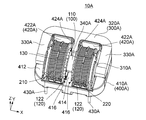
- the composite line filter 10A according to the second embodiment of the present invention is connected to one of the outer legs 320 of the magnetic core 300 in the composite line filter 10 according to the first embodiment.
- the configuration is such that part of the portion 330 is removed.
- differences between the composite line filter 10A and the composite line filter 10 will be described.
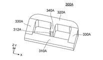
- the magnetic core 300A of the composite line filter 10A of the present embodiment includes a middle leg (core part) 310A, one outer leg 320A, two connecting parts 330A, One protrusion 340A.
- the connecting portion 330A and the outer leg 320A are continuous with each other, and both ends of the middle leg 310A are connected to form a main magnetic path portion. Further, the middle leg 310A, the outer leg 320A, and the connecting portion 330A form a closed magnetic path portion.
- the shape of the magnetic core 300A in which the middle leg 310A, the outer leg 320A, and the connecting portion 330A are connected in this way is a rectangular frame shape when viewed along the Z direction.
- the protrusion 340A protrudes along the Y direction from the center of the outer leg 320A in the X direction toward the middle leg 310A. Similar to the first embodiment, a predetermined gap (gap) is provided between the tip of the projection 340A and the facing portion 312A of the middle leg 310A.
- the magnetic core 300A is formed in a vertically symmetrical shape, as can be understood from FIG.
- the protrusion 340A has a thickness t2 which is a dimension in the X direction.
- the thickness t2 is set to 0.5 mm or more and D2 / 2 mm or less (D2: internal method in the X direction of the closed magnetic path portion), similarly to the thickness t1 of the first embodiment.
- the distance (gap width) Wg2 between the protrusion 340A and the facing portion 312A is set to 0.1 mm or more and 2.0 mm or less. Both are for the same reason as in the first embodiment. Also in the present embodiment, since the thickness t2 and the gap width Wg2 of the protrusion 340A are within the predetermined ranges, the characteristics including the normal mode inductance Ln can be improved.
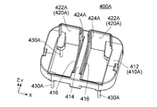
- the terminal block 400A has a base portion 410A, two wall portions 420A, and two pairs of pins 430A (see FIG. 16).
- Each wall 420A has a main portion 422A and a partition plate 424A.
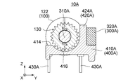
- the base portion 410 ⁇ / b> A includes a substantially rectangular frame portion 412 and a beam portion 414 provided at the center of the frame portion 412. A part of the upper surface of the frame portion 412 is provided with an inclination corresponding to the shape of the magnetic core 300A as shown in FIG. Further, as shown in FIG. 21, the beam portion 414 is formed with a recess 416 that accommodates a part of the gear 130 (see FIGS. 9 and 13) of the bobbin 100.
- Each wall 420A is provided along one of the two inner edges facing each other in the Y direction of the base 410A.
- the main portions 422A of the two wall portions 420A are arranged in the X direction with the beam portion 414 interposed therebetween, and protrude upward (+ Z direction) from the base portion 410A.
- the partition plate 424A of the two wall portions 420A protrudes along the Y direction from the inner end portions in the X direction of the two main portions 422.
- the pins 430A are provided at positions slightly apart from the four corners of the base portion 410A.
- the gear 130 and the protrusion 340 ⁇ / b> A partially overlap when viewed along the X direction. Therefore, the diameter of the gear 130 is not limited by the presence of the protrusion 340A, and by increasing the diameter of the gear 130, the winding can be firmly wound even with a small driving force.
- the protrusion 340 ⁇ / b> A is located between the coils 210 and 220 and between the gears 130 in the X direction. Further, the protrusion 340A is located between a part of the outer leg 320A and the facing part 312A of the middle leg 310A in the Y direction.
- the partition plate 424A is provided on both sides of the protrusion 340A in the X direction, and is located between the coils 210 and 220.
- the gear 130 is also located between the coils 210 and 220 in the X direction.
- each gear 130 is located between the protrusion 340 ⁇ / b> A and one of the inner flanges 122 in the X direction.
- the gear 130 overlaps the partition plate 424A at least partially when viewed along the Y direction.
- a special space for installation in the X direction with respect to that part Do not need. Therefore, 10 A of composite line filters of this Embodiment can make the dimension of an axial direction small compared with the line filter of patent document 1 which provides a gear in an outer collar part.
- the present invention has been specifically described with reference to the embodiment, but the present invention is not limited to this, and various modifications and changes are possible.
- the integrally formed magnetic cores 300 and 300A are used.
- the magnetic cores 300 and 300A may be configured by combining a plurality of core components so that no gap is formed.
- the shape of the magnetic cores 300 and 300A can be changed as long as predetermined characteristics can be realized.
- the present invention relates to Japanese Patent Application No. 2016-124759 filed with the Japan Patent Office on June 23, 2016, and Japanese Patent Application No. 2016-125888 filed with the Japan Patent Office on June 24, 2016. The contents of which are incorporated herein by reference.
Landscapes
- Engineering & Computer Science (AREA)
- Power Engineering (AREA)
- Microelectronics & Electronic Packaging (AREA)
- Manufacturing & Machinery (AREA)
- Chemical & Material Sciences (AREA)
- Composite Materials (AREA)
- Coils Or Transformers For Communication (AREA)
Abstract
Les bobines 210,220 d'un filtre de ligne composite 10 sont séparées dans la direction axiale (direction X) et enroulées sur une bobine 100. La bobine 100 est fixée à une portion 310 d'une partie de chemin magnétique fermé d'un noyau magnétique 300. Une partie de chemin magnétique secondaire 340 du noyau magnétique 300 fait saillie à partir d'une portion 320 de la partie de chemin magnétique fermé, et est positionnée entre les bobines 210, 220 dans la direction axiale (direction X) La bobine 100 comporte un engrenage 130. L'engrenage 130 est positionné entre les bobines 210, 220 dans la direction axiale.
Priority Applications (3)
| Application Number | Priority Date | Filing Date | Title |
|---|---|---|---|
| US16/311,658 US11328864B2 (en) | 2016-06-23 | 2017-06-22 | Compound line filter |
| EP17815473.8A EP3460814B1 (fr) | 2016-06-23 | 2017-06-22 | Filtre de ligne composite |
| KR1020197002072A KR102421432B1 (ko) | 2016-06-23 | 2017-06-22 | 복합라인필터 |
Applications Claiming Priority (4)
| Application Number | Priority Date | Filing Date | Title |
|---|---|---|---|
| JP2016-124759 | 2016-06-23 | ||
| JP2016124759A JP6543225B2 (ja) | 2016-06-23 | 2016-06-23 | 複合ラインフィルタ |
| JP2016-125887 | 2016-06-24 | ||
| JP2016125887A JP6873615B2 (ja) | 2016-06-24 | 2016-06-24 | 複合ラインフィルタ |
Publications (1)
| Publication Number | Publication Date |
|---|---|
| WO2017222007A1 true WO2017222007A1 (fr) | 2017-12-28 |
Family
ID=60783377
Family Applications (1)
| Application Number | Title | Priority Date | Filing Date |
|---|---|---|---|
| PCT/JP2017/022979 Ceased WO2017222007A1 (fr) | 2016-06-23 | 2017-06-22 | Filtre de ligne composite |
Country Status (4)
| Country | Link |
|---|---|
| US (1) | US11328864B2 (fr) |
| EP (1) | EP3460814B1 (fr) |
| KR (1) | KR102421432B1 (fr) |
| WO (1) | WO2017222007A1 (fr) |
Cited By (1)
| Publication number | Priority date | Publication date | Assignee | Title |
|---|---|---|---|---|
| CN112789699A (zh) * | 2018-10-25 | 2021-05-11 | 株式会社自动网络技术研究所 | 电抗器 |
Families Citing this family (5)
| Publication number | Priority date | Publication date | Assignee | Title |
|---|---|---|---|---|
| KR102219671B1 (ko) | 2019-05-17 | 2021-02-24 | (주) 트랜스온 | 스퀘어 타입 라인 필터 및 이의 제작 방법 |
| KR102127433B1 (ko) | 2019-06-07 | 2020-06-26 | (주) 트랜스온 | 스퀘어 타입 라인필터용 코일 어셈블리 |
| KR102127430B1 (ko) | 2019-06-07 | 2020-06-26 | (주) 트랜스온 | 스퀘어 타입 라인필터용 코일 어셈블리 |
| US20220059274A1 (en) * | 2020-08-21 | 2022-02-24 | Astec International Limited | Adjustable Spacer For Magnetic Transformers And Inductors |
| KR102473031B1 (ko) | 2021-04-09 | 2022-12-02 | (주) 트랜스온 | 전기적 특성이 향상된 스퀘어 타입 라인 필터 |
Citations (3)
| Publication number | Priority date | Publication date | Assignee | Title |
|---|---|---|---|---|
| JPH01134909A (ja) * | 1987-11-19 | 1989-05-26 | Tokin Corp | コイルボビン |
| JPH10144546A (ja) * | 1996-11-13 | 1998-05-29 | Tokin Corp | チョークコイル |
| JP2007080951A (ja) * | 2005-09-12 | 2007-03-29 | Tokyo Parts Ind Co Ltd | ラインフィルタおよびその製造方法 |
Family Cites Families (27)
| Publication number | Priority date | Publication date | Assignee | Title |
|---|---|---|---|---|
| US2558293A (en) * | 1949-12-29 | 1951-06-26 | Advance Transformer Co | Apparatus for starting and operating gaseous discharge devices |
| US2992386A (en) * | 1958-08-01 | 1961-07-11 | Forbro Design Inc | Power supply with adjustable stabilized output voltage |
| US3022458A (en) * | 1959-05-29 | 1962-02-20 | Joseph G Sola | Voltage regulating apparatus |
| US3576508A (en) * | 1969-08-25 | 1971-04-27 | Litton Precision Prod Inc | Transformer apparatus |
| US5266916A (en) * | 1988-03-08 | 1993-11-30 | Kijima Co., Ltd. | Compact transformer |
| JPH0737292Y2 (ja) * | 1988-03-23 | 1995-08-23 | ティーディーケイ株式会社 | ラインフイルタ用分割型ボビンとこの分割型ボビンを使用するラインフイルタ |
| US5272831A (en) * | 1992-09-02 | 1993-12-28 | Regent Lighting Corporation | Insect extermination and illumination device and operating circuit therefor |
| DE69429551T2 (de) * | 1993-03-12 | 2002-06-20 | Matsushita Electric Industrial Co., Ltd. | Netzfilter |
| EP0962947A3 (fr) * | 1994-11-04 | 2000-01-19 | Matsushita Electric Industrial Co., Ltd. | Filtre de ligne |
| JPH08339925A (ja) | 1995-06-09 | 1996-12-24 | Tokin Corp | 分割型巻線ボビンおよびコイル装置 |
| JP3063619B2 (ja) * | 1996-05-20 | 2000-07-12 | 株式会社村田製作所 | チョークコイル |
| JP3871152B2 (ja) | 1996-10-22 | 2007-01-24 | Necトーキン株式会社 | チョークコイル |
| JP2000021658A (ja) | 1998-07-01 | 2000-01-21 | Matsushita Electric Ind Co Ltd | ラインフィルタ |
| TW464063U (en) * | 2000-04-21 | 2001-11-11 | Delta Electronics Inc | Improved filter device |
| JP3074742U (ja) | 2000-04-28 | 2001-01-26 | 三和無線株式会社 | ラインフィルター |
| US20050280481A1 (en) * | 2004-06-18 | 2005-12-22 | Hsueh-Ming Shih | Wave filter assembly |
| US20080211615A1 (en) * | 2005-09-29 | 2008-09-04 | Greatchip Technology Co., Ltd. | Inverter transformer |
| JP4844438B2 (ja) * | 2007-03-14 | 2011-12-28 | パナソニック株式会社 | ラインフィルタ |
| CN201112050Y (zh) * | 2007-10-06 | 2008-09-10 | 台达电子工业股份有限公司 | 一种电感器的基座 |
| JP2010016234A (ja) | 2008-07-04 | 2010-01-21 | Hitachi Ferrite Electronics Ltd | インターリーブ制御力率改善回路用チョークコイル |
| CN201298430Y (zh) * | 2008-09-26 | 2009-08-26 | 国琏电子(上海)有限公司 | 变压器 |
| JP5062439B2 (ja) * | 2009-04-28 | 2012-10-31 | Tdk株式会社 | インターリーブ用pfcチョークコイル |
| JP5385083B2 (ja) | 2009-10-19 | 2014-01-08 | 東京パーツ工業株式会社 | ラインフィルタ |
| JP5192582B1 (ja) * | 2011-10-31 | 2013-05-08 | Necトーキン株式会社 | チョークコイル |
| KR101422898B1 (ko) * | 2011-12-20 | 2014-07-24 | 삼성전기주식회사 | 코일 부품 및 이의 제조 방법 |
| US9929640B2 (en) * | 2012-11-20 | 2018-03-27 | Lg Innotek Co., Ltd. | Integrated-type transformer |
| JP5455276B1 (ja) | 2013-04-17 | 2014-03-26 | Necトーキン株式会社 | チョークコイル |
-
2017
- 2017-06-22 WO PCT/JP2017/022979 patent/WO2017222007A1/fr not_active Ceased
- 2017-06-22 EP EP17815473.8A patent/EP3460814B1/fr active Active
- 2017-06-22 US US16/311,658 patent/US11328864B2/en active Active
- 2017-06-22 KR KR1020197002072A patent/KR102421432B1/ko active Active
Patent Citations (3)
| Publication number | Priority date | Publication date | Assignee | Title |
|---|---|---|---|---|
| JPH01134909A (ja) * | 1987-11-19 | 1989-05-26 | Tokin Corp | コイルボビン |
| JPH10144546A (ja) * | 1996-11-13 | 1998-05-29 | Tokin Corp | チョークコイル |
| JP2007080951A (ja) * | 2005-09-12 | 2007-03-29 | Tokyo Parts Ind Co Ltd | ラインフィルタおよびその製造方法 |
Cited By (2)
| Publication number | Priority date | Publication date | Assignee | Title |
|---|---|---|---|---|
| CN112789699A (zh) * | 2018-10-25 | 2021-05-11 | 株式会社自动网络技术研究所 | 电抗器 |
| CN112789699B (zh) * | 2018-10-25 | 2022-08-30 | 株式会社自动网络技术研究所 | 电抗器 |
Also Published As
| Publication number | Publication date |
|---|---|
| KR102421432B1 (ko) | 2022-07-14 |
| KR20190020788A (ko) | 2019-03-04 |
| US20190198242A1 (en) | 2019-06-27 |
| EP3460814A1 (fr) | 2019-03-27 |
| US11328864B2 (en) | 2022-05-10 |
| EP3460814A4 (fr) | 2019-12-25 |
| EP3460814B1 (fr) | 2022-03-16 |
Similar Documents
| Publication | Publication Date | Title |
|---|---|---|
| KR102421432B1 (ko) | 복합라인필터 | |
| JP5804628B2 (ja) | コイル部品 | |
| JP6132461B2 (ja) | コイル部品 | |
| JP5459173B2 (ja) | 誘導機器 | |
| EP2437273B1 (fr) | Élément magnétique | |
| JP5842282B2 (ja) | コイル部品 | |
| JP2016066720A (ja) | 磁気結合型リアクトル | |
| JP2016207941A (ja) | コイル部品 | |
| JP6283976B2 (ja) | コモンモードチョーク | |
| JP2019091747A (ja) | 変圧器、およびコイルボビン | |
| JP6132553B2 (ja) | コイル部品 | |
| JP6781043B2 (ja) | 複合磁路インダクタ | |
| JP2015056422A (ja) | リアクトル装置及びリアクトル装置の製造方法 | |
| JP6873615B2 (ja) | 複合ラインフィルタ | |
| JP2017069349A (ja) | コイル部品 | |
| JP7220189B2 (ja) | 複合ラインフィルタ | |
| JP6543225B2 (ja) | 複合ラインフィルタ | |
| JP3235972U (ja) | インダクタ、内側平角線片及び外側平角線片 | |
| JP2006202922A (ja) | リアクトル | |
| JP7331639B2 (ja) | リアクトル | |
| JP2014132602A (ja) | チョークコイル | |
| CN209571877U (zh) | 具有减少振动和噪声的结构的分裂芯部型马达的定子 | |
| CN101779257B (zh) | 复合磁性元件 | |
| JP2013084860A (ja) | 縦型トランス | |
| JP2005303229A (ja) | トランス |
Legal Events
| Date | Code | Title | Description |
|---|---|---|---|
| 121 | Ep: the epo has been informed by wipo that ep was designated in this application |
Ref document number: 17815473 Country of ref document: EP Kind code of ref document: A1 |
|
| NENP | Non-entry into the national phase |
Ref country code: DE |
|
| ENP | Entry into the national phase |
Ref document number: 2017815473 Country of ref document: EP Effective date: 20181221 |
|
| ENP | Entry into the national phase |
Ref document number: 20197002072 Country of ref document: KR Kind code of ref document: A |