WO2018011910A1 - Structure de montage de rotor et séparateur centrifuge - Google Patents
Structure de montage de rotor et séparateur centrifuge Download PDFInfo
- Publication number
- WO2018011910A1 WO2018011910A1 PCT/JP2016/070695 JP2016070695W WO2018011910A1 WO 2018011910 A1 WO2018011910 A1 WO 2018011910A1 JP 2016070695 W JP2016070695 W JP 2016070695W WO 2018011910 A1 WO2018011910 A1 WO 2018011910A1
- Authority
- WO
- WIPO (PCT)
- Prior art keywords
- rotor
- shaft
- piece
- inclined surface
- hole
- Prior art date
- Legal status (The legal status is an assumption and is not a legal conclusion. Google has not performed a legal analysis and makes no representation as to the accuracy of the status listed.)
- Ceased
Links
Images








Classifications
-
- B—PERFORMING OPERATIONS; TRANSPORTING
- B04—CENTRIFUGAL APPARATUS OR MACHINES FOR CARRYING-OUT PHYSICAL OR CHEMICAL PROCESSES
- B04B—CENTRIFUGES
- B04B9/00—Drives specially designed for centrifuges; Arrangement or disposition of transmission gearing; Suspending or balancing rotary bowls
- B04B9/08—Arrangement or disposition of transmission gearing ; Couplings; Brakes
-
- B—PERFORMING OPERATIONS; TRANSPORTING
- B04—CENTRIFUGAL APPARATUS OR MACHINES FOR CARRYING-OUT PHYSICAL OR CHEMICAL PROCESSES
- B04B—CENTRIFUGES
- B04B7/00—Elements of centrifuges
-
- B—PERFORMING OPERATIONS; TRANSPORTING
- B04—CENTRIFUGAL APPARATUS OR MACHINES FOR CARRYING-OUT PHYSICAL OR CHEMICAL PROCESSES
- B04B—CENTRIFUGES
- B04B7/00—Elements of centrifuges
- B04B7/02—Casings; Lids
- B04B7/06—Safety devices ; Regulating
-
- B—PERFORMING OPERATIONS; TRANSPORTING
- B04—CENTRIFUGAL APPARATUS OR MACHINES FOR CARRYING-OUT PHYSICAL OR CHEMICAL PROCESSES
- B04B—CENTRIFUGES
- B04B9/00—Drives specially designed for centrifuges; Arrangement or disposition of transmission gearing; Suspending or balancing rotary bowls
- B04B9/12—Suspending rotary bowls ; Bearings; Packings for bearings
-
- B—PERFORMING OPERATIONS; TRANSPORTING
- B04—CENTRIFUGAL APPARATUS OR MACHINES FOR CARRYING-OUT PHYSICAL OR CHEMICAL PROCESSES
- B04B—CENTRIFUGES
- B04B9/00—Drives specially designed for centrifuges; Arrangement or disposition of transmission gearing; Suspending or balancing rotary bowls
- B04B9/08—Arrangement or disposition of transmission gearing ; Couplings; Brakes
- B04B2009/085—Locking means between drive shaft and rotor
Definitions
- This invention relates to a centrifuge, and more particularly to a rotor mounting structure.
- FIG. 1 shows the internal configuration of the centrifuge described in Patent Document 1.
- reference numeral 1 denotes a rotating shaft whose axis is in the vertical direction
- 2 denotes an upper part of the rotating shaft.
- Fig. 2 shows a mounted rotating head.
- Reference numeral 3 denotes a rotor disposed on the upper part of the rotary head 2
- reference numeral 4 denotes a lid covering the upper part of the rotor 3.
- the rotor 3 includes a plurality of sample insertion portions 5 and also includes rotor holes 6 and 7 into which the rotary head 2 is inserted, a frame 8, male members 9-1 and 9-2, guide pins 10, and the like.
- the rotor hole 6 is a circular hole having a constant diameter
- the rotor hole 7 is a circular hole having a diameter smaller toward the inside of the hole.
- the male mold members 9-1 and 9-2 are rotatable around the rotation shafts 11-1 and 11-2 disposed horizontally inside the rotor hole 6, and the center of gravity is rotated around the rotation shafts 11-1 and 11-2. And have convex portions 13-1 and 13-2 on the opposite side of the axis 12 of the rotary shaft 1 below the center of gravity.
- the male members 9-1 and 9-2 are attached to the frame 8, and the frame 8 is attached to the rotor 3.
- the rotor 3 includes through holes 14 and 15, and screws are formed in the through holes 15 formed in the frame 8.
- the rotary head 2 includes a rotor coupling portion 16 and a drive pin 17 at the top.
- the rotor coupling portion 16 has a cylindrical shape centered on the axis 12 of the rotary shaft 1 and has an annular recess 18 on the inner surface.
- the rotary head 2 includes a cylindrical portion 19 that fits into the rotor hole 6 and a truncated cone portion 20 that fits into the rotor hole 7.
- the lid 4 has a knob 21 and a screw portion 22 for screwing into the through hole 15 of the frame 8.
- the guide pin 10 can move only between the drive pins 17, and when the rotary head 2 rotates, power is transmitted from the drive pins 17 to the guide pins 10 and the rotor 3 rotates. When the rotary head 2 stops, the rotor 3 stops together with the rotary head 2.
- the center of gravity of the male members 9-1 and 9-2 is directly below the rotary shafts 11-1 and 11-2.
- the male members 9-1 and 9-2 are inside the rotor coupling portion 16.
- the male members 9-1 and 9-2 move so that the convex portions 13-1 and 13-2 fit into the concave portion 18 by centrifugal force, and the convex portions 13-1 and 13-2 are moved.
- a force that causes the rotor 3 to be detached from the rotary head 2 a force that lifts the rotor 3
- Power is added. Therefore, even when a force for separating the rotor 3 that is not assumed during rotation from the rotary head 2 is applied, the convex portions 13-1 and 13-2 and the concave portion 18 are not separated from each other, and reliable fixing can be realized. It has become a thing.
- the male members 9-1 and 9-2 are arranged in the rotor 3 so as to be rotatable, and the male members 9-1 and 9- are caused by the centrifugal force generated when the rotor 3 rotates. 2 is moved (rotated), and the convex portions 13-1 and 13-2 of the male members 9-1 and 9-2 are fitted into the concave portions 18 of the rotary head 2, whereby the rotor 3 is fixed to the rotary head 2. It has become.
- An object of the present invention is to provide a rotor mounting structure that ensures that the rotor can be securely fixed by simply placing it, and that the rotor can be easily assembled.
- the tip end side of the shaft is a cylindrical rotor coupling portion, and the annular concave portion is formed on the inner peripheral surface of the rotor coupling portion.
- An annular convex portion is formed on the more distal end side, and a corner of the inner circumferential surface of the annular convex portion on the annular concave portion side is chamfered to form a first shaft inclined surface, and the annular concave portion is formed from the first shaft inclined surface.
- the surface that reaches the bottom surface is a second shaft inclined surface that forms an acute angle with the bottom surface
- the rotor has a rotor hole into which the shaft is inserted
- a mounting bracket is disposed in the rotor hole.
- the mounting bracket includes a main body accommodated in the rotor coupling portion, first and second pieces arranged in a piece arrangement hole formed in the main body in a direction perpendicular to the rotation center axis of the rotor, a base portion, and a base portion
- Two extension parts which are bent in the same direction from both ends of the two parts, and two arm parts extended in an arc shape so as to surround the rotation center axis from the tip of each extension part, and the piece is arranged on the main body
- the base portion is mounted between the leaf spring in which the extension portion and the arm portion are inserted into the piece placement hole through the opening formed above the piece placement hole so as to communicate with the hole, and the body mounted on the body.
- the first piece has a first groove into which an arm formed on the longer extension is inserted, and rotates with the first side wall located on one end side of the piece arrangement hole across the first groove.
- a second piece having a second groove into which an arm part formed in a shorter extension part is inserted, and the piece sandwiching the second groove.
- a second side wall portion located on the other end side of the arrangement hole and a second center portion located on the first center portion, and each outer side surface of the first side wall portion and the second side wall portion is an arc.
- Each outer surface has a first inclined surface and a second inclined surface corresponding to a shape formed by the first shaft inclined surface and the second shaft inclined surface, and the first and second inclined surfaces are formed in a stopped state of the rotor.
- Each of the second pieces is positioned by the arm portion and positioned in the piece arrangement hole. When the rotor is rotated by the rotation of the shaft, the first and second pieces are distant. The first inclined surface abuts against the first shaft inclined surface by moving so as to protrude from one end and the other end of the piece arrangement hole against the spring force of the leaf spring by force, and the lift of the rotor with respect to the shaft is second. The inclined surface is prevented by contacting the inclined surface of the second shaft.
- the first and second pieces move horizontally by the centrifugal force generated by the rotation of the rotor and come into contact with the rotor coupling portion of the shaft, whereby the rotor and the shaft are fastened, and the rotor is also lifted. It can be prevented, and can be installed simply by placing the rotor on the shaft.
- the pin is not necessary and only the first and second pieces need to be inserted into the piece arrangement hole. In comparison, assembly can also be performed easily.
- FIG. 1 is a cross-sectional view showing a conventional rotor mounting structure.
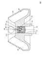
- FIG. 2 is a sectional view showing an embodiment of a rotor mounting structure according to the present invention.
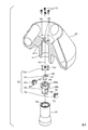
- FIG. 3 is an exploded perspective view of the rotor mounting structure shown in FIG. 4A is a perspective view of the mounting bracket in FIG. 4B is a cross-sectional view of the mounting bracket in FIG.
- FIG. 5A is a front view showing a partial cross section of the shaft in FIG. 3.
- FIG. 5B is an enlarged view of a cross-sectional portion of FIG. 5A.
- FIG. 5C is a perspective view showing a partial cross section of the shaft in FIG. 3.
- 6A is a plan view of the main body in FIG.
- FIG. 6B is a front view of the main body in FIG. 6C is a bottom view of the main body in FIG. 6D is a side view of the main body in FIG. 6E is a perspective view of the main body in FIG. 6F is a cross-sectional view of the main body in FIG.
- FIG. 7A is a plan view of the first piece in FIG.
- FIG. 7B is a front view of the first piece in FIG. 3.
- FIG. 7C is a bottom view of the first piece in FIG. 3.
- FIG. 7D is a side view of the first piece in FIG. 3.
- FIG. 7E is a perspective view of the first piece in FIG.
- FIG. 7F is a cross-sectional view of the first piece in FIG.
- FIG. 8A is a plan view of the second piece in FIG.
- FIG. 8B is a front view of the second piece in FIG.
- FIG. 8C is a bottom view of the second piece in FIG. 3.
- FIG. 8D is a side view of the second piece in FIG. 3.
- FIG. 8E is a perspective view of the second piece in FIG.
- FIG. 8F is a cross-sectional view of the second piece in FIG. 9A is a plan view of the leaf spring in FIG.
- FIG. 9B is a front view of the leaf spring in FIG.
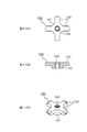
- FIG. 10C is a perspective view of the restraint in FIG.
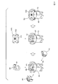
- FIG. 11 is a view for explaining an assembly procedure of the mounting bracket shown in FIG. 4A.
- FIG. 12A is a front view showing the positional relationship between the first piece and the second piece in the mounting bracket.
- FIG. 12B is a bottom view showing the positional relationship between the first piece and the second piece in the mounting bracket.
- FIG. 12C is a cross-sectional view showing the positional relationship between the first piece and the second piece in the mounting bracket.
- FIG. 12D is a perspective view showing the positional relationship between the first piece and the second piece in the mounting bracket.
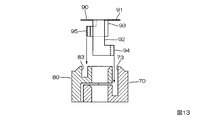
- FIG. 13 is a view for explaining the incorporation of a leaf spring into the first piece and the second piece.
- FIG. 14A is a plan view showing a state of the first and second pieces and the leaf spring when rotation is stopped.
- FIG. 14B is a front view with a partial cross section showing the state of the first and second pieces and the leaf spring when rotation is stopped.
- FIG. 14C is a plan view showing a state of the first and second pieces and the leaf spring during rotation.
- FIG. 14D is a plan view with a partial cross section showing the state of the first and second pieces and the leaf spring during rotation.
- FIG. 15A is a diagram illustrating a state in which the mounting bracket is inserted into the rotor coupling portion of the shaft when the rotor is mounted on the shaft.
- FIG. 15B is a diagram illustrating a state in which the mounting bracket is inserted into the rotor coupling portion of the shaft when the rotor is mounted on the shaft.
- FIG. 15C is a diagram illustrating a state in which the mounting bracket is accommodated in the rotor coupling portion of the shaft when the rotor is mounted on the shaft.
- FIG. 15D is a diagram illustrating a state in which the mounting bracket is accommodated in the rotor coupling portion of the shaft when the rotor is mounted on the shaft.
- FIG. 15E is a diagram illustrating a state in which the mounting bracket is accommodated in the rotor coupling portion of the shaft when the rotor is mounted on the shaft.
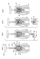
- FIG. 16A is a cross-sectional view showing the relationship between the first and second pieces and the rotor coupling portion when rotation is stopped.
- FIG. 16B is a cross-sectional view showing the relationship between the first and second pieces and the rotor coupling portion during rotation.
- FIG. 17A is a cross-sectional view showing a state where the first inclined surface of the first piece and the first shaft inclined surface are in contact with each other.
- FIG. 17B is a cross-sectional view showing a state where the second inclined surface of the first piece and the second shaft inclined surface are in contact with each other.
- FIG. 18A is a diagram for explaining a force generated in a state where the first inclined surface of the first piece and the first shaft inclined surface are in contact with each other.
- FIG. 18B is a diagram showing the balance of forces shown in FIG. 18A.
- FIG. 19A is a diagram for explaining a force generated in a state where the first and second inclined surfaces of the first piece are in contact with the first and second shaft inclined surfaces.
- FIG. 19B is a diagram showing a balance of the forces shown in FIG. 19A.
- FIG. 20A is a diagram for explaining the release when the first and second pieces do not return and the shaft and the rotor are locked.
- FIG. 20B is a diagram for explaining release when the first and second pieces do not return and the shaft and the rotor are locked.
- FIG. 20C is a diagram for explaining the release when the first and second pieces do not return and the shaft and the rotor are locked.
- FIG. 20D is a diagram for explaining the release when the first and second pieces do not return and the shaft and the rotor are locked.
- FIG. 21A is a view for explaining release when the shaft and the rotor hole are fixed.
- FIG. 21B is a view for explaining the release when the shaft and the rotor hole are fixed.
- FIG. 22A is a diagram for explaining a comparative example of leaf springs.
- FIG. 22B is a diagram showing a comparative example of leaf springs.
- FIG. 22C is a diagram showing a comparative example of leaf springs.
- FIG. 23A is a perspective view showing a comparative example of the mounting bracket.
- FIG. 23B is a cross-sectional view showing a comparative example of the mounting bracket.
- 24A is a perspective view showing another shape example of the first piece.
- 24B is a cross-sectional view of the first piece shown in FIG. 24A.
- FIG. 25A is a perspective view showing another shape example of the second piece.
- FIG. 25B is a cross-sectional view of the second piece shown in FIG. 25A.
- FIG. 26A is a cross-sectional view showing the relationship between the first and second pieces and the rotor coupling portion shown in FIGS. 24A and 24B and FIGS. 25A and 25B when rotation is stopped.
- FIG. 26B is a cross-sectional view showing the relationship between the first and second pieces and the rotor coupling portion shown in FIGS. 24A and 24B and FIGS. 25A and 25B during rotation.
- FIG. 2 shows an internal configuration of a centrifuge having an embodiment of a rotor mounting structure according to the present invention.
- 30 is a shaft attached to a motor drive shaft (not shown).
- Reference numeral 40 denotes a rotor attached to the shaft 30.
- Reference numeral 50 denotes a mounting bracket attached to the rotor 40.
- FIG. 3 is an exploded view of the structure shown in FIG. 2, and the mounting bracket 50 includes a main body 60, a first piece 70, a second piece 80, and a leaf spring, as shown in FIG. 90 and a restraint 100.
- FIGS. 4A and 4B show a mounting bracket 50 constructed by incorporating the first and second pieces 70 and 80, the leaf spring 90 and the holding member 100 into the main body 60.
- the shaft 30 includes a large-diameter portion 31, a small-diameter portion 32, and a tapered portion 33 that connects the large-diameter portion 31 and the small-diameter portion 32.
- the distal end side of the small-diameter portion 32 has a cylindrical shape.
- the rotor coupling portion 34 is formed.
- An annular concave portion 35 is formed on the inner peripheral surface of the rotor coupling portion 34, and an annular convex portion 36 that protrudes from the bottom surface 35 a of the annular concave portion 35 is formed on the tip side of the annular concave portion 35.
- a corner of the inner peripheral surface of the annular convex portion 36 on the annular concave portion 35 side is chamfered to form a first shaft inclined surface 36a.
- a surface from the first shaft inclined surface 36a to the bottom surface 35a of the annular recess 35 is a second shaft inclined surface 36b that forms an acute angle with the bottom surface 35a.
- a drive pin 37 projects from the inner bottom surface 34 a of the rotor coupling portion 34.
- three drive pins 37 are provided at equiangular intervals on the circumference, and the tip of each drive pin 37 is tapered.
- a circular hole 38 is formed in the center of the inner bottom surface 34a for use in bolting the shaft 30 to the drive shaft of the motor.
- the main body 60 of the mounting bracket 50 has a shape as shown in FIGS. 6A-6F, and is roughly divided into a cylindrical portion 61, a flange portion 62 positioned on the upper end side of the cylindrical portion 61, and a lower end side of the cylindrical portion 61. It consists of a drive pin contact part 63.
- a large piece arrangement hole 64 is formed through the cylindrical portion 61 in a direction perpendicular to the axis.
- the piece arrangement hole 64 has a square hole shape.
- An opening 65 is formed above the piece placement hole 64 so as to communicate with the piece placement hole 64 and open upward through the cylindrical portion 61 and the flange portion 62.
- the opening 65 has a rectangular shape with rounded corners.
- recesses 66 are formed in a circular arc shape on the outer sides of the long side portions of the opening 65 facing each other.
- the arcuate outer shapes of the two recesses 66 are located on the same circumference, and an opening 65 is formed so as to cross the circumference.
- a groove 67 is further formed on the upper surface of the flange portion 62 so as to form a cross shape.
- the groove 67 is formed from the pair of short side portions of the opening 65 and the two concave portions 66 to the outer peripheral surface of the flange portion 62.
- the depth of the groove 67 is shallower than the depth of the recess 66.
- four screw holes 68 a are formed in the flange portion 62, and a circular hole 68 b is formed below the piece arrangement hole 64 at the axial center position of the cylindrical portion 61.
- the drive pin contact portion 63 is composed of six prisms 69 arranged radially at equiangular intervals around the hole 68b.
- the prism 69 is formed so as to protrude from the lower surface of the cylindrical portion 61, and the tip thereof has a sharp shape.
- the first piece 70 has a shape as shown in FIGS. 7A-7F, and has a central portion 71 and a side wall portion 72 located on one side of the central portion 71.
- a groove 73 is provided between the side wall portion 72.
- the central portion 71 and the side wall portion 72 are connected by a connecting portion 74 located below the groove 73.
- the side surface 71a of the central portion 71 on the groove 73 side has a square shape, and the width of the central portion 71 on the opposite side is made narrower than the width of the side surface 71a forming the rectangular shape, and the bottom surface 70a of the piece 70
- the shape is assumed to be substantially convex.
- a circular hole 75 is formed in the central portion 71 so as to penetrate in the vertical direction, and an inclined surface 76 is formed by cutting away a portion of the upper end periphery of the hole 75 opposite to the groove 73.
- the side wall portion 72 is higher than the central portion 71, and the outer side surface 72a has an arc shape.
- a second inclined surface 72b and a first inclined surface 72c are formed which are respectively concentric with the arc shape of the outer surface 72a, and the first inclined surface 72c is formed on the first inclined surface 72c.
- the upper end of the subsequent side wall 72 is a horizontal plane 72d.
- the shape formed by the first inclined surface 72c and the second inclined surface 72b is a shape corresponding to the shape formed by the first shaft inclined surface 36a and the second shaft inclined surface 36b of the shaft 30, that is, the first inclined surface.
- Each inclination angle of 72c and the 2nd inclined surface 72b is corresponded with each inclination angle of the 1st shaft inclined surface 36a and the 2nd shaft inclined surface 36b.
- the center of gravity of the piece 70 having the shape as described above is located closer to the side wall 72 than the central axis of the hole 75.
- the second piece 80 has a shape as shown in FIGS. 8A-8F, and has a central portion 81 and a side wall portion 82 located on one side of the central portion 81.
- a groove 83 is provided between the side wall portion 82.
- the outer side surface 82a of the side wall portion 82 has an arc shape
- the bottom surface 80a of the piece 80 has a U shape in which the side wall portion 82 forms an intermediate portion of the U shape.
- Both U-shaped leg portions are constituted by outer wall portions 84 and 85, and a central portion 81 is located on the outer wall portions 84 and 85, and is formed by the outer wall portions 84 and 85 and a connecting portion 86 located below the groove 83. It is supported and floated from the bottom surface 80a.
- the piece 80 can stand independently by having such a U-shaped bottom face 80a.
- Both the side surface 81 a on the groove 83 side and the side surface 81 b on the opposite side of the central portion 81 are shaped like a dogleg like the side surface 71 a of the central portion 71 of the piece 70.
- a circular hole 87 is formed through the central portion 81 in the vertical direction, and an inclined surface 88 is formed by cutting away a portion of the upper end periphery of the hole 87 opposite to the groove 83.
- a second inclined surface 82b and a first inclined surface 82c are formed on the upper end side of the outer surface 82a of the side wall portion 82.
- the second inclined surface 82b and the first inclined surface 82c are respectively concentric with the arc shape of the outer surface 82a.
- the upper end of the subsequent side wall 82 is a horizontal plane 82d.
- the horizontal plane 82d, the first inclined plane 82c, and the second inclined plane 82b have the same shape as the horizontal plane 72d, the first inclined plane 72c, and the second inclined plane 72b of the side wall 72 of the piece 70.
- the horizontal plane 82d has the same height as the top surface of the central portion 81.
- the center of gravity of the piece 80 is located closer to the side wall 82 than the central axis of the hole 87.
- the leaf spring 90 has a shape as shown in FIGS. 9A-9D.
- the base 91 has a substantially elliptical shape, and two long and short extensions 92, 93 formed by bending 90 degrees in the same direction from both ends of the base 91.
- two arm portions 94 and 95 formed by extending in the width direction of the extension portions 92 and 93 from the distal ends of the extension portions 92 and 93, respectively.
- a circular hole 96 is formed in the center of the base 91.
- the two arm portions 94 and 95 are formed in an arc shape so as to surround the central axis of the hole 96, and the width and length of the two arm portions 94 and 95 are equal to each other, as shown in FIG. 9A.
- the distances L1 and L2 from the center axis of the hole 96 are also equal.
- the restraint 100 has a shape as shown in FIGS. 10A to 10C, and includes a cylindrical part 101 and four projecting parts 102 that project from the peripheral surface on the upper end side of the cylindrical part 101 so as to form a cross shape.
- a screw hole 103 is formed at the center of the cylindrical portion 101.
- FIG. 11 shows the assembly of each part constituting the mounting bracket 50.
- the piece 70 and the piece 80 are inserted into the piece arrangement hole 64 of the main body 60 and arranged.
- the leaf spring 90 the extension portions 92 and 93 and the arm portions 94 and 95 are inserted into the piece arrangement hole 64 through the opening 65, and the base portion 91 is inserted into the recess 66 of the main body 60.
- the restraint 100 is mounted on the main body 60.
- the cylindrical portion 101 of the holding member 100 is inserted into the recess 66, and the projecting portion 102 having a cross shape is inserted into the groove 67 of the main body 60.
- the pieces 70 and 80, the leaf spring 90, and the holding member 100 are assembled in the main body 60 in this way, and the mounting bracket 50 is completed.
- FIG. 12A-12D show the relationship between the piece 70 and the piece 80 incorporated in the main body 60.
- the central portion 81 of the piece 80 is positioned on the central portion 71 of the piece 70 and overlaps with each other.
- the side wall portion 72 and the side wall portion 82 of the piece 80 are positioned on opposite sides of the portion where the central portions 71 and 81 overlap.
- the convex portion (a part of the central portion 71) of the bottom surface 70a having a substantially convex shape of the piece 70 enters a U-shape of the bottom surface 80a of the U-shape of the piece 80.
- the pieces 70 and 80 have the same height.
- FIG. 13 shows a state in which the leaf spring 90 is assembled.
- the arm portion 94 formed on the longer extension portion 92 of the leaf spring 90 is inserted into the groove 73 of the piece 70, and the shorter extension portion. 93 is inserted into the groove 83 of the piece 80.
- 14A and 14B show the relationship between the pieces 70 and 80 and the leaf spring 90, and the base 91 of the leaf spring 90 is partially broken.
- the arm portions 94 and 95 are in contact with the side surface 71a of the central portion 71 of the piece 70 and the side surface 81a of the central portion 81 of the piece 80, respectively, and the piece 70 and the piece 80 are positioned by the arm portions 94 and 95, that is, the main body.
- the arm portions 94 and 95 hold the predetermined positions in the 60 piece arrangement holes 64.
- the mounting bracket 50 is attached to the rotor 40.
- the rotor 40 has a rotor hole 41 into which the shaft 30 is inserted, and a mounting bracket 50 is attached in the rotor hole 41.
- the four bolts 110 (see FIG. 3) are used for attachment, and the four bolts 110 are formed in the main body 60 of the mounting bracket 50 through the holes 42 formed in the bottom surface 41a of the rotor hole 41.
- the mounting bracket 50 is screwed and fixed to the bottom surface 41a of the rotor hole 41 by being screwed into the screw hole 68a.
- the base 91 and the restraint 100 of the leaf spring 90 are sandwiched and fixed between the bottom surface 41a of the rotor hole 41 and the main body 60 by fixing the main body 60 to the bottom surface 41a of the rotor hole 41 in this way.
- 68b are located on the rotation center axis 43 of the rotor 40, and the screw hole 103 of the retainer 100 is also located on the rotation center axis 43.
- a circular hole 44 is formed on the bottom surface 41 a of the rotor hole 41 so as to be positioned on the rotation center shaft 43.
- the rotor 40 provided with the mounting bracket 50 is attached to the shaft 30 as shown in FIG.
- the rotor 40 is an angle rotor and includes a plurality of container holes 45 for accommodating and holding a container containing a sample.
- the rotor hole 41 has a shape that matches the small-diameter portion 32 and the tapered portion 33 of the shaft 30, and the opening side (lower end side) is formed by a tapered surface 41 b that gradually increases in diameter toward the opening.
- the tapered portion 33 of the shaft 30 is a holding surface that holds the rotor 40, and the tapered surface 41 b is mounted on the tapered portion 33 so that the rotor 40 is attached to the shaft 30.
- FIGS. 15A-15E show how the mounting bracket 50 attached to the rotor 40 is inserted into and accommodated in the rotor coupling portion 34 of the shaft 30 when the rotor 40 is mounted on the shaft 30.
- the six prisms 69 formed in the lower part of the main body 60 have a sharp shape, and the three drive pins 37 projecting from the rotor coupling portion 34 have a tapered shape. Even if the drive pin 37 hits as shown in FIG. 15B, the prism 69 is drawn between the drive pins 37 as shown in FIG. 15C. As a result, as shown in FIGS.
- the three drive pins 37 are arranged alternately between adjacent prisms 69, and the body portions of the drive pins 37 and the prisms 69 are in contact with each other.
- the prism 69 receives power from the drive pin 37, whereby the rotor 40 can be rotated.
- the pieces 70 and 80 are positioned in the piece arrangement hole 64 of the main body 60, and the pieces 70 and 80 and the annular convex portion 36 of the shaft 30 are separated as shown in FIG. 16A. ing.
- the pieces 70 and 80 move in the opposite directions in the piece arrangement hole 64 against the spring force of the leaf spring 90 by centrifugal force, and the pieces 70 and 80 are moved to the piece arrangement hole.
- 64 protrudes from one end and the other end of 64 as shown in FIG. 16B.
- the first inclined surfaces 72 c and 82 c of the pieces 70 and 80 are in contact with the first shaft inclined surface 36 a of the annular convex portion 36 of the shaft 30.
- FIG. 17A and 17B show two aspects of the contact state between the pieces 70 and 80 and the annular convex portion 36 of the shaft 30 on the piece 70 side.
- FIG. 17A shows that the first inclined surface 72c of the piece 70 is the first.
- FIG. 17B shows a state where the first inclined surface 72c and the second inclined surface 72b of the piece 70 are in contact with the first inclined shaft surface 36a and the second inclined shaft surface 36b, respectively. Indicates the state of FIG. 17B shows a case where a floating force exceeding the fastening force between the rotor 40 and the shaft 30 due to the contact state of FIG.
- the force generated in the state shown in FIG. 17A The force F1 received by the piece 70 due to the centrifugal force and the normal direction from the first shaft inclined surface 36a.
- the force F3 received by the piece 70 along the balance between the force F2 received by the piece 70 along the normal direction from the surface constituting the piece arrangement hole 64 of the main body 60 is balanced.
- the shaft 30 and the rotor 40 are in a fastened state.
- the angle ⁇ 1 formed by the first inclined surface 72c of the piece 70 with respect to the vertical direction may be 20 degrees or more and 70 degrees or less, preferably 30 degrees or more and 60 degrees or less, and more preferably 40 degrees or more and 50 degrees or less. Is done. The same applies to the angle of the first inclined surface 82c of the piece 80.
- FIG. 19A and 19B show the force generated in the state shown in FIG. 17B, from the force F4 received by the piece 70 due to the centrifugal force and the surface constituting the piece arrangement hole 64 of the main body 60.
- the force F7 received by the piece 70 is balanced. Therefore, the rotor 40 does not float up.
- the angle ⁇ 2 formed by the second inclined surface 72b of the piece 70 with respect to the vertical direction may be 90 degrees or less.
- the pieces 70 and 80 do not return to the initial positions, and, for example, as shown in FIG. 17B, the locked state remains in contact with the second shaft inclined surface 36b. There is. Such a locked state may occur, for example, when the pieces 70 and 80 adhere to the shaft 30 due to a leaked sample or the like, or the leaf spring 90 is damaged.
- the tool 120 includes a grip part 121 and a shaft part 122.
- a screw 122a is formed on the shaft part 122.
- the tip of the shaft portion 122 is tapered.
- the locked state of the shaft 30 and the rotor 40 can be released, and the rotor 40 can be detached from the shaft 30.
- the front end of the shaft portion 122 is tapered, and the pieces 80 and 70 are formed with inclined surfaces 88 and 76 for drawing the shaft portion 122 into the holes 87 and 75, respectively. , 75. In this way, in this example, the two pieces 70 and 80 can be moved by one operation of inserting the tool 120 to release the locked state.
- FIGS. 21A and 21B show the release when the tapered surface 41b of the rotor hole 41 and the tapered portion 33 of the shaft 30 constituting the holding surface for holding the rotor 40 are fixed, for example.
- the tip of the shaft portion 122 hits the bolt 130 that holds the shaft 30 on the drive shaft of the motor, and the tool 120 is further turned to tighten the shaft portion 122 to the bolt.
- the rotor 40 can be lifted as shown in FIG. 21A, and the sticking can be released. Since the screw 122a of the tool 120 is screwed into the screw hole 103 of the holding member 50 attached to the rotor 40, the tool 40 is lifted to lift the rotor 40 as shown in FIG. 21B. be able to.
- the two pieces 70 and 80 have a configuration in which their central portions 71 and 81 overlap each other, the height direction and the horizontal direction can be reduced, and space can be saved accordingly. it can.
- the pieces 70 and 80 are simply moved by one operation of inserting the tool 120 into the holes 75 and 87 provided in the pieces 70 and 80. The lock state can be released.
- the leaf spring 90 has the shape shown in FIGS. 9A-9D and the two arms 94 and 95 have the same shape, the same spring force can be applied to the two pieces 70 and 80. can do. For example, in the case of a simple U-shaped leaf spring 140 as shown in FIG.
- FIG. 22A since the lengths of the two arm portions 141 and 142 are different, the same spring constant is shown in FIG. 22B.
- the leaf spring 140 ′ or the leaf spring 140 ′′ shown in FIG. 22C is shaped.
- the leaf spring 140 ′ shown in FIG. 22B is a case where the longer arm 142 with hatching is used as a reference.
- the width of the shorter arm portion 141 must be reduced, which makes it difficult to use in strength.
- the leaf spring 140 ′′ shown in FIG. In this case, the width of the longer arm portion 141 becomes extremely large, and it becomes difficult to use it because of space.
- the plate spring 90 has a shape as shown in FIGS. 9A to 9D, whereby such problems of strength and space can be solved.
- the restraint 100 is thicker than the cross-shaped projecting portion 102, and has a cylindrical portion 101 accommodated in the concave portion 66 of the main body 60 in the center, and a screw hole 103 is formed in this portion. Therefore, the length of the screw hole 103 can be increased.
- the mounting bracket 50 ′ is configured as shown in FIGS. 23A and 23B, and the main body 60 ′ and the restraint 100 ′ are simply stacked in the shape as shown in FIGS. 23A and 23B, In order to reduce the size, the restraint 100 ′ must be thin, that is, the length of the screw hole 103 is shortened.
- the screw hole 103 meshes with the screw 122a of the tool 120 for releasing the lock state, and shortening the screw hole 103 causes a problem in strength and is easily damaged. In this respect, in this example, the strength of the screw hole 103 can be ensured.
- the pieces 70 and 80 are configured such that the first inclined surfaces 72c and 82c and the second inclined surfaces 72b and 82b are formed on the upper ends of the side walls 72 and 82, respectively.
- the positions where the 72c and 82c and the second inclined surfaces 72b and 82b are formed are not limited to this, and may be changed.
- FIGS. 24A and 24B and FIGS. 25A and 25B show the shapes of the pieces 70 ′ and 80 ′ in which the formation positions of the first inclined surfaces 72c and 82c and the second inclined surfaces 72b and 82b are changed, respectively.
- 26B shows the relationship between the pieces 70 ′ and 80 ′ and the rotor coupling portion 34 when the rotation is stopped and when the rotation is stopped, as in FIGS. 16A and 16B described above.
- portions corresponding to FIGS. 7A-7F and portions corresponding to FIGS. 8A-8F in FIGS. 25A and 25B are denoted by the same reference numerals.
- the pieces 70 ′ and 80 ′ have the first inclined surfaces 72 c and 82 c and the second inclined surfaces 72 b and 82 b at positions lower than the upper ends of the side walls 72 and 82, not the upper ends of the side walls 72 and 82. Accordingly, as shown in FIGS. 26A and 26B, the shaft 30 ′ is also longer in the direction of the rotation center axis 43 of the annular convex portion 36 than the shaft 30 shown in FIGS. 5A-5C. Thus, the positions of the first shaft inclined surface 36a and the second shaft inclined surface 36b are lowered.
- G1 indicates the position of the center of gravity of the piece 70 '
- G2 indicates the position of the center of gravity of the piece 80'.
- the heights h of the centroids G1 and G2 in the direction of the rotation center axis 43 are equal to each other, and 72c and 82c are the first inclined surfaces of the pieces 70 'and 80' during rotation, and the first shaft inclined surface 36a of the shaft 30 '.
- the height position in the direction of the rotation center axis 43 in contact with the center of gravity G1, G2 is configured to coincide with the height position of the center of gravity G1, G2.
- the first rotation is caused. A force for inclining the pieces 70 'and 80' to the pieces 70 'and 80' in contact with the shaft inclined surface 36a is not generated, and the pieces 70 'and 80' can be prevented from being inclined.
- the pieces 70 ′ and 80 ′ are inclined and fixed while being in contact with the second shaft inclined surface 36b, and cannot move ( This is advantageous in preventing the occurrence of problems such as being locked.
- the occurrence of the inclination of the pieces can be reduced. If the height position where the first inclined surfaces 72c and 82c of the piece abut the first shaft inclined surface 36a at a point is close to the height position of the gravity centers G1 and G2 of the pieces so as to be within an allowable range in design. Good.
Landscapes
- Centrifugal Separators (AREA)
Abstract
Selon la présente invention, un adaptateur de montage est monté dans un trou de rotor. L'adaptateur de montage comporte: un corps principal; des première et deuxième pièces disposées dans des trous d'agencement de pièces formés en pénétrant dans le corps principal dans une direction orthogonale à l'axe central de rotation d'un rotor; un ressort à lame muni de deux sections de bras; et un presseur monté sur le corps principal de telle façon qu'une partie d'embase du ressort à lame soit serrée entre le presseur et le corps principal. Les première et deuxième pièces présentent chacune une rainure dans laquelle est insérée la section de bras du ressort à lame. Lorsque le rotor tourne, les première et deuxième pièces résistent à la force élastique du ressort à lame sous l'effet d'une force centrifuge, dépassent des trous d'agencement de pièces et entrent en contact avec une partie de couplage de rotor d'un arbre. L'assemblage côté rotor peut être effectué facilement au moyen de cette structure, dans laquelle le rotor peut être monté sur l'arbre simplement en mettant le rotor en place.
Priority Applications (5)
| Application Number | Priority Date | Filing Date | Title |
|---|---|---|---|
| PCT/JP2016/070695 WO2018011910A1 (fr) | 2016-07-13 | 2016-07-13 | Structure de montage de rotor et séparateur centrifuge |
| CN201680087558.5A CN109475880B (zh) | 2016-07-13 | 2016-07-13 | 转子的安装结构及离心分离器 |
| US16/316,246 US10532366B2 (en) | 2016-07-13 | 2016-07-13 | Rotor attachment structure and centrifuge |
| JP2016566297A JP6192860B1 (ja) | 2016-07-13 | 2016-07-13 | ロータの取付構造及び遠心分離機 |
| EP16908814.3A EP3485978B1 (fr) | 2016-07-13 | 2016-07-13 | Structure de montage de rotor et séparateur centrifuge |
Applications Claiming Priority (1)
| Application Number | Priority Date | Filing Date | Title |
|---|---|---|---|
| PCT/JP2016/070695 WO2018011910A1 (fr) | 2016-07-13 | 2016-07-13 | Structure de montage de rotor et séparateur centrifuge |
Publications (1)
| Publication Number | Publication Date |
|---|---|
| WO2018011910A1 true WO2018011910A1 (fr) | 2018-01-18 |
Family
ID=59798917
Family Applications (1)
| Application Number | Title | Priority Date | Filing Date |
|---|---|---|---|
| PCT/JP2016/070695 Ceased WO2018011910A1 (fr) | 2016-07-13 | 2016-07-13 | Structure de montage de rotor et séparateur centrifuge |
Country Status (5)
| Country | Link |
|---|---|
| US (1) | US10532366B2 (fr) |
| EP (1) | EP3485978B1 (fr) |
| JP (1) | JP6192860B1 (fr) |
| CN (1) | CN109475880B (fr) |
| WO (1) | WO2018011910A1 (fr) |
Families Citing this family (4)
| Publication number | Priority date | Publication date | Assignee | Title |
|---|---|---|---|---|
| DE102014112501B4 (de) * | 2014-08-29 | 2017-07-27 | Andreas Hettich Gmbh & Co. Kg | Zentrifuge |
| JP6376040B2 (ja) * | 2015-05-27 | 2018-08-22 | 株式会社デンソー | 接合体、及び、その接合体を用いるアクセル装置 |
| JP7089884B2 (ja) | 2018-01-25 | 2022-06-23 | 株式会社久保田製作所 | 遠心分離機 |
| JP7837144B2 (ja) | 2020-05-29 | 2026-03-30 | ファイバーライト・セントリフュージ・エルエルシー | 遠心分離機ロータのバランシングを行うためのシステムおよび方法 |
Citations (6)
| Publication number | Priority date | Publication date | Assignee | Title |
|---|---|---|---|---|
| JPS5442337B2 (fr) | 1972-09-18 | 1979-12-13 | ||
| US4753631A (en) * | 1986-11-03 | 1988-06-28 | E. I. Du Pont De Nemours And Company | Speed limiting arrangement for a centrifuge rotor having an axial mounting bolt |
| US20080146429A1 (en) * | 2006-12-13 | 2008-06-19 | Thermo Electron Corporation | Rotor assembly and method of connection thereof |
| JP2009082922A (ja) * | 1998-05-06 | 2009-04-23 | Beckman Coulter Inc | 遠心分離機のロータロック装置、ロータロック機構およびロータ組立体 |
| JP5442337B2 (ja) * | 2009-06-30 | 2014-03-12 | 株式会社久保田製作所 | 遠心分離機、遠心分離機用ロータ |
| JP2016002512A (ja) * | 2014-06-16 | 2016-01-12 | 株式会社久保田製作所 | 遠心分離機とロータ体 |
Family Cites Families (9)
| Publication number | Priority date | Publication date | Assignee | Title |
|---|---|---|---|---|
| FR2727037A1 (fr) * | 1994-11-21 | 1996-05-24 | Jouan | Centrifugeuse a rotor demontable et a dispositif de blocage axial du rotor sur l'arbre d'entrainement |
| DE19721335C2 (de) * | 1996-06-14 | 1999-07-29 | Kendro Lab Prod Gmbh | Vorrichtung zur Fixierung eines Rotors auf einer Antriebswelle |
| FR2770154B1 (fr) * | 1997-10-23 | 1999-11-26 | Jouan | Centrifugeuse a rotor demontable et a dispositif de blocage axial du rotor sur une tete d'entrainement, et rotor pour une telle centrifugeuse |
| DE102008045556A1 (de) * | 2008-09-03 | 2010-03-04 | Thermo Electron Led Gmbh | Zentrifuge mit einem Kupplungselement zur axialen Verriegelung eines Rotors |
| DE102012011531B4 (de) * | 2012-06-08 | 2016-11-10 | Thermo Electron Led Gmbh | Set aus Antriebskopf und Nabe zur lösbaren Verbindung eines Antriebes mit einem Rotor einer Zentrifuge für einen weiten Drehzahlbereich |
| FR3005273A1 (fr) * | 2013-05-02 | 2014-11-07 | Afi Centrifuge | Centrifugeuse de laboratoire comprenant des moyens pour le verrouillage en translation d'un rotor sur un arbre moteur d'entrainement |
| DE102013107681B4 (de) * | 2013-07-18 | 2018-02-08 | Andreas Hettich Gmbh & Co. Kg | Zentrifuge |
| DE102014002126B4 (de) * | 2014-02-17 | 2019-01-17 | Thermo Electron Led Gmbh | Antriebskopf zur lösbaren Verbindung eines Antriebes mit einem Rotor einer Zentrifuge, diesen umfassendes Set und Zentrifuge |
| DE102015113854A1 (de) * | 2015-08-20 | 2017-02-23 | Andreas Hettich Gmbh & Co. Kg | Rotor einer Zentrifuge |
-
2016
- 2016-07-13 WO PCT/JP2016/070695 patent/WO2018011910A1/fr not_active Ceased
- 2016-07-13 CN CN201680087558.5A patent/CN109475880B/zh active Active
- 2016-07-13 JP JP2016566297A patent/JP6192860B1/ja active Active
- 2016-07-13 EP EP16908814.3A patent/EP3485978B1/fr active Active
- 2016-07-13 US US16/316,246 patent/US10532366B2/en active Active
Patent Citations (6)
| Publication number | Priority date | Publication date | Assignee | Title |
|---|---|---|---|---|
| JPS5442337B2 (fr) | 1972-09-18 | 1979-12-13 | ||
| US4753631A (en) * | 1986-11-03 | 1988-06-28 | E. I. Du Pont De Nemours And Company | Speed limiting arrangement for a centrifuge rotor having an axial mounting bolt |
| JP2009082922A (ja) * | 1998-05-06 | 2009-04-23 | Beckman Coulter Inc | 遠心分離機のロータロック装置、ロータロック機構およびロータ組立体 |
| US20080146429A1 (en) * | 2006-12-13 | 2008-06-19 | Thermo Electron Corporation | Rotor assembly and method of connection thereof |
| JP5442337B2 (ja) * | 2009-06-30 | 2014-03-12 | 株式会社久保田製作所 | 遠心分離機、遠心分離機用ロータ |
| JP2016002512A (ja) * | 2014-06-16 | 2016-01-12 | 株式会社久保田製作所 | 遠心分離機とロータ体 |
Also Published As
| Publication number | Publication date |
|---|---|
| CN109475880A (zh) | 2019-03-15 |
| JP6192860B1 (ja) | 2017-09-06 |
| EP3485978A1 (fr) | 2019-05-22 |
| CN109475880B (zh) | 2020-11-27 |
| JPWO2018011910A1 (ja) | 2018-07-19 |
| US10532366B2 (en) | 2020-01-14 |
| US20190299221A1 (en) | 2019-10-03 |
| EP3485978A4 (fr) | 2020-01-01 |
| EP3485978B1 (fr) | 2020-12-16 |
Similar Documents
| Publication | Publication Date | Title |
|---|---|---|
| JP6192860B1 (ja) | ロータの取付構造及び遠心分離機 | |
| ES2651617T3 (es) | Conjunto de conmutador giratorio | |
| US10638818B2 (en) | Slider with reboundable pull-tab | |
| US7402107B2 (en) | Drive plate assembly structure for torque converter | |
| KR20190085663A (ko) | 절삭 휠 탈부착장치 | |
| JP5346530B2 (ja) | コネクタモジュール用の保持フレーム | |
| JP5838505B2 (ja) | 警報器 | |
| WO2018061110A1 (fr) | Dispositif de pompe | |
| JP4654359B2 (ja) | レンズ駆動装置の製造方法 | |
| JP2016195963A (ja) | ロータの取付構造及び遠心分離機 | |
| CN215291875U (zh) | 无基座执手 | |
| JP5432622B2 (ja) | 配線器具取付体とその取付方法 | |
| CN211545709U (zh) | 固定装置和工程机械 | |
| JP4842096B2 (ja) | パネル固定機構 | |
| US11118638B2 (en) | Reverse input lock clutch | |
| TWI806433B (zh) | 電動棘輪扳手 | |
| CN215069222U (zh) | 蜂鸣器装配机构 | |
| KR102238506B1 (ko) | 스냅링 전용 안전 케이싱 | |
| JPS6040991Y2 (ja) | 回転ヘツドドラムの取付装置 | |
| JPH10208520A (ja) | 埋込型照明器具 | |
| KR20210121735A (ko) | 다축 드릴 헤드 | |
| KR101617517B1 (ko) | 회전 유닛을 구비하는 조명 장치 | |
| WO2025197514A1 (fr) | Dispositif d'éclairage | |
| TW202500877A (zh) | 吊扇 | |
| JP2008121385A (ja) | フロアパネルの固定構造 |
Legal Events
| Date | Code | Title | Description |
|---|---|---|---|
| ENP | Entry into the national phase |
Ref document number: 2016566297 Country of ref document: JP Kind code of ref document: A |
|
| 121 | Ep: the epo has been informed by wipo that ep was designated in this application |
Ref document number: 16908814 Country of ref document: EP Kind code of ref document: A1 |
|
| NENP | Non-entry into the national phase |
Ref country code: DE |
|
| ENP | Entry into the national phase |
Ref document number: 2016908814 Country of ref document: EP Effective date: 20190213 |