WO2018016285A1 - Procédé de fabrication de plaque de polarisation et dispositif de fabrication associé - Google Patents
Procédé de fabrication de plaque de polarisation et dispositif de fabrication associé Download PDFInfo
- Publication number
- WO2018016285A1 WO2018016285A1 PCT/JP2017/023915 JP2017023915W WO2018016285A1 WO 2018016285 A1 WO2018016285 A1 WO 2018016285A1 JP 2017023915 W JP2017023915 W JP 2017023915W WO 2018016285 A1 WO2018016285 A1 WO 2018016285A1
- Authority
- WO
- WIPO (PCT)
- Prior art keywords
- polarizing plate
- end mill
- blade
- manufacturing
- deformed
- Prior art date
- Legal status (The legal status is an assumption and is not a legal conclusion. Google has not performed a legal analysis and makes no representation as to the accuracy of the status listed.)
- Ceased
Links
Images


Classifications
-
- B—PERFORMING OPERATIONS; TRANSPORTING
- B23—MACHINE TOOLS; METAL-WORKING NOT OTHERWISE PROVIDED FOR
- B23C—MILLING
- B23C3/00—Milling particular work; Special milling operations; Machines therefor
-
- B—PERFORMING OPERATIONS; TRANSPORTING
- B23—MACHINE TOOLS; METAL-WORKING NOT OTHERWISE PROVIDED FOR
- B23C—MILLING
- B23C5/00—Milling-cutters
- B23C5/02—Milling-cutters characterised by the shape of the cutter
- B23C5/10—Shank-type cutters, i.e. with an integral shaft
-
- G—PHYSICS
- G02—OPTICS
- G02B—OPTICAL ELEMENTS, SYSTEMS OR APPARATUS
- G02B5/00—Optical elements other than lenses
- G02B5/30—Polarising elements
Definitions
- the present invention relates to a method of manufacturing a deformed polarizing plate and a manufacturing apparatus thereof. More specifically, the present invention relates to a method for manufacturing a deformed polarizing plate having a concave R portion and / or a hole and a manufacturing apparatus therefor. The present invention also relates to an optical film using the deformed polarizing plate. Further, the present invention relates to an image display device such as a liquid crystal display device, an organic EL display device, and a PDP using the deformed polarizing plate and the optical film.
- a punching process in which an irregular shaped blade shape is formed and the polarizing plate is punched, or a cutting process using laser irradiation is included.
- the former punching process it has been found that the polarizing plate is cracked or broken due to the damage of the pressing plate.
- laser processing it has been found that the polarizing plate is discolored by heat.
- there is a tendency for cracks and breaks to occur in a recessed portion such as small diameter hole processing and small diameter concave R processing.
- the shaving residue contains an adhesive, but the shaving residue containing such an adhesive is a blade. It has been newly found that accumulation at the root portion may cause problems such as adhesion to the blade and increased rotation resistance, and the blade does not rotate stably.
- the present invention is a method for producing a deformed polarizing plate having a small-diameter concave R portion and / or a hole, in particular, and the occurrence or discoloration of cracks or breaks generated in the deformed polarizing plate during processing.
- Another object of the present invention is to provide a method for manufacturing a deformed polarizing plate and an apparatus for manufacturing the same, in which shavings are prevented from accumulating at the base of the end mill blade.
- the method for producing the deformed polarizing plate of the present invention is as follows: A method for producing a deformed polarizing plate having a concave R portion, Including a step of forming the concave R portion using a cutting means that a blade comes into contact with and cuts from a lateral direction with respect to the cutting surface,
- the cutting means is an end mill,
- the rotation direction of the end mill is counterclockwise when viewed from the shank side when the end mill blade is a left-handed right-handed twist, or
- the rotation direction of the end mill is clockwise when viewed from the shank side when the end mill blade is a right-handed left-handed twist. It is characterized by that.
- the method for producing a deformed polarizing plate according to the present invention is a technique for cutting a polarizing plate, and since the polarizing plate is generally a laminate of an adhesive layer and a film, an adhesive is included in the shaving residue during cutting.
- the method for producing a deformed polarizing plate of the present invention has the above-described configuration, so that it is possible to move the shaving residue to the blade edge side in the cutting of the laminate having the adhesive layer. It becomes possible to manufacture a deformed polarizing plate that suppresses accumulation of shavings at the base of the blade.
- the said root part means the attachment part vicinity of the shank side which attaches an end mill with respect to the blade edge of an end mill.
- the method for producing a deformed polarizing plate according to the present invention is particularly difficult to suppress by using means in which the blade comes into contact with the cutting surface of the polarizing plate from the lateral direction. It is possible to suppress the occurrence of cracks and creases and discoloration, and to produce a deformed polarizing plate having a concave portion with a small diameter.
- the concave R portion refers to a portion having a concave portion and a curved portion, and includes a corner portion of the concave portion having a curved shape such as a circle, an ellipse, or a substantially circular shape.
- the convex R portion refers to a portion having a convex portion and a curved portion, and includes a convex portion having a curved portion such as a circle, an ellipse, or a substantially circular shape.
- the concave R part and the convex R part shown in FIG. 1 can be mentioned.
- the end mill blade is a right blade, for example, as shown in FIG. 3, which has an outer peripheral blade that can be used when viewed clockwise from the shank side (clockwise, positive rotation).
- a left blade means what is equipped with the outer periphery blade which can be used at the time of seeing from the shank side counterclockwise (counterclockwise rotation, reverse rotation).
- FIG. 3 when the end mill blade is viewed from the side, when the end mill blade is viewed from the side, the angle of the end mill blade is inclined leftward and upward with respect to the center axis of the end mill. The one that is attached. Also, the end mill blade is twisted to the right, for example, opposite to the case of FIG.
- the radius of the concave R portion is preferably 5 mm or less.
- the radius of the concave R portion is the radius of the circle when the R portion is circular, and the radius of curvature when the R portion is not circular such as an ellipse or a substantially circular shape.
- the edge of the end mill has a downward edge.
- the term “the edge of the end mill blade is downward” includes not only the case where the blade edge is directed vertically downward but also the case where the blade edge is substantially downward or the like and includes a case where a predetermined angle is formed with respect to the vertical downward direction.
- the blade edge side is more downward than the shank side and is downward enough to allow the scrap to be moved to the blade edge side to the extent that the effects of the present invention can be obtained.
- the manufacturing apparatus of the deformed polarizing plate of the present invention is An apparatus for producing a deformed polarizing plate having a concave R portion, A cutting means is provided that a blade comes into contact with the cutting surface from the lateral direction and cuts.
- the cutting means is an end mill, The rotation direction of the end mill is counterclockwise when viewed from the shank side when the end mill blade is a left-handed right-handed twist, or The rotation direction of the end mill is clockwise when viewed from the shank side when the end mill blade is a right-handed left-handed twist. It is characterized by that.
- the radius of the concave R portion is preferably 5 mm or less.
- the edge of the end mill has a downward edge.
- the manufacturing method of the deformed polarizing plate of the present invention is as follows: A method for producing a deformed polarizing plate having a hole, Including the step of forming the hole using an end mill,
- the cutting means is an end mill,
- the rotation direction of the end mill is counterclockwise when viewed from the shank side when the end mill blade is a left-handed right-handed twist, or
- the rotation direction of the end mill is clockwise when viewed from the shank side when the end mill blade is a right-handed left-handed twist. It is characterized by that.
- a hole part means the part which has holes, such as circular, an ellipse, a substantially circular shape, square shape, for example, and means what penetrated the polarizing plate.
- holes such as circular, an ellipse, a substantially circular shape, square shape, for example, and means what penetrated the polarizing plate.
- the radius of the hole is 5 mm or less.
- the radius of the hole means the radius of the circle when the hole is circular, and the radius of curvature when the hole is not circular such as an ellipse or a substantially circular shape.
- the edge of the end mill has a downward edge.
- the manufacturing apparatus of the deformed polarizing plate of the present invention is An apparatus for manufacturing a deformed polarizing plate having a hole, With an end mill, The rotation direction of the end mill is counterclockwise when viewed from the shank side when the end mill blade is a left-handed right-handed twist, or The rotation direction of the end mill is clockwise when viewed from the shank side when the end mill blade is a right-handed left-handed twist. It is characterized by that.
- the radius of the hole is preferably 5 mm or less.
- the edge of the end mill has a downward edge.
- An example of the deformed polarizing plate obtained by the method for producing a deformed polarizing plate of the present invention is shown.
- An example of embodiment of the manufacturing method of the deformed polarizing plate of this invention is shown.
- An example of embodiment of the manufacturing method of the deformed polarizing plate of this invention is shown.
- the schematic diagram containing the manufacturing method of the deformed polarizing plate of this invention is shown.
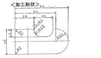
- the processing shape implemented in the Example of this invention is shown.
- the method for producing the deformed polarizing plate of the present invention is as follows: A method for producing a deformed polarizing plate having a concave R portion, Including a step of forming the concave R portion using a cutting means that a blade comes into contact with and cuts from a lateral direction with respect to the cutting surface,
- the cutting means is an end mill,
- the rotation direction of the end mill is counterclockwise when viewed from the shank side when the end mill blade is a left-handed right-handed twist, or
- the rotation direction of the end mill is clockwise when viewed from the shank side when the end mill blade is a right-handed left-handed twist. It is characterized by that.
- the manufacturing method of the deformed polarizing plate of the present invention is as follows: A method for producing a deformed polarizing plate having a hole, Including the step of forming the hole using an end mill,
- the cutting means is an end mill,
- the rotation direction of the end mill is counterclockwise when viewed from the shank side when the end mill blade is a left-handed right-handed twist, or
- the rotation direction of the end mill is clockwise when viewed from the shank side when the end mill blade is a right-handed left-handed twist. It is characterized by that.
- the method for producing a deformed polarizing plate according to the present invention includes a step of forming the concave R portion and / or the hole portion using a cutting means in which a blade comes into contact with the cutting surface in a lateral direction and cuts. .
- a cutting means in which a blade comes into contact with the cutting surface in a lateral direction and cuts.
- a deformed polarizing plate having a concave portion with a small diameter and / or a hole.
- an end mill end mill process
- a cutting means which a blade contacts and cuts from a horizontal direction with respect to a cutting surface.
- an end mill is a type of cutting tool that can be machined in a direction perpendicular to the rotation axis, unlike a drill that is machined only in the axial direction (only for drilling).
- the polarizing plate cutting surface is rotated while rotating the blade portion of the end mill corresponding to the blade in this case with respect to the polarizing plate to be formed with the concave R portion and / or the hole portion.
- the blade comes into contact with and cuts from the lateral direction.
- the cutting process of a polarizing plate is continued and it processes into a predetermined irregularly-shaped polarizing plate.
- the rotation of the blade portion that performs cutting is performed, for example, as shown in FIGS.
- the polarizing plate can be cut by an end mill in the processing direction while the rotation is performed continuously, stepwise, or intermittently. In this case, cutting is performed in a state where the blade portion of the end mill is in contact with the cutting surface from the lateral direction.
- the blade hits and cuts from the upper surface of the polarizing plate as a workpiece (in FIG. 2, the direction parallel to the cutting surface, the direction perpendicular to the polarizing plate surface). Will be.
- the method for producing a deformed polarizing plate of the present invention has the above-described configuration, so that in the cutting of a laminate having an adhesive layer, it is possible to move the cutting scrap toward the blade tip side, and as a result, particularly the root of the end mill blade. Therefore, it is possible to manufacture a deformed polarizing plate that suppresses the accumulation of shavings on the part.
- the concave R portion has a small diameter or is fine, it can be suitably manufactured and processed while suppressing generation of cracks and breaks and discoloration that occur during processing.
- the radius of the concave R portion is 5 mm or less, it can be easily manufactured and processed.
- the radius may be 1 mm or more and 5 mm or less, and may be 1 mm or more and 4 mm or less, or 2 mm or more and 3 mm or less.
- the radius may be 1 mm or more and 5 mm or less, and may be 1 mm or more and 4 mm or less, or 2 mm or more and 3 mm or less.
- the edge of the end mill can be used, for example, upward or sideways, but the edge of the end mill is preferably downward.
- the manufacturing apparatus of the deformed polarizing plate of the present invention is An apparatus for producing a deformed polarizing plate having a concave R portion, A cutting means is provided that a blade comes into contact with the cutting surface from the lateral direction and cuts.
- the cutting means is an end mill, The rotation direction of the end mill is counterclockwise when viewed from the shank side when the end mill blade is a left-handed right-handed twist, or The rotation direction of the end mill is clockwise when viewed from the shank side when the end mill blade is a right-handed left-handed twist. It is characterized by that.
- the cutting means that includes the end mill and that the blade comes into contact with and cuts from the above-described cutting surface from the lateral direction is appropriately provided in the apparatus by a known method. it can.
- the radius of the concave R portion is 5 mm or less, it can be easily manufactured and processed.
- the radius may be 1 mm or more and 5 mm or less, and may be 1 mm or more and 4 mm or less, or 2 mm or more and 3 mm or less.
- the edge of the end mill can be used, for example, upward or sideways, but the edge of the end mill is preferably downward.
- the manufacturing apparatus of the deformed polarizing plate of the present invention is An apparatus for manufacturing a deformed polarizing plate having a hole, With an end mill, The rotation direction of the end mill is counterclockwise when viewed from the shank side when the end mill blade is a left-handed right-handed twist, or The rotation direction of the end mill is clockwise when viewed from the shank side when the end mill blade is a right-handed left-handed twist. It is characterized by that.
- the above-mentioned end mill can be appropriately provided in the apparatus by a known technique.
- the radius of the hole is 5 mm or less, it can be easily manufactured and processed.
- the radius may be 1 mm or more and 5 mm or less, and may be 1 mm or more and 4 mm or less, or 2 mm or more and 3 mm or less.
- the edge of the end mill can be used, for example, upward or sideways, but the edge of the end mill is preferably downward.
- the number of blades is preferably 1 to 6, and the number of blades may be 1 to 4.
- the rake angle of the end mill blade is preferably 0 to less than 15 °, and may be 3 to 12 °. If the rake angle is 15 ° or more, the blade tends to be chipped.
- the clearance angle of the end mill blade is preferably greater than 0 ° and less than 20 °, and may be 3 to 15 °.
- the relief angle is 0 °, the film is rubbed with the film, and when the relief angle is 20 ° or more, the blade is easily chipped.
- the twist angle of the blade portion of the end mill is preferably ⁇ 75 ° to 75 °, and may be ⁇ 65 ° to 65 °. When the twist angle exceeds the above range, it becomes easy to cause a scrap discharge failure.
- the blade diameter (outer diameter) ⁇ of the end mill blade is preferably 3 to 30 mm, and may be 5 to 25 mm. If the blade diameter ⁇ is smaller than 3 mm, it is easy to break, and if it is larger than 30 mm, it is difficult to perform fine profile processing.
- the feed speed of the end mill blade is preferably 100 to 10,000 mm / min, and may be 200 to 8000 mm / min.
- the rotation direction of the end mill is the left when viewed from the shank side (toward the blade edge). It is characterized by rotating (counterclockwise, reverse rotation). Further, when the end mill blade is a right blade left-handed twist, the rotation direction of the end mill is clockwise (clockwise, normal rotation) when viewed from the shank side (toward the blade edge).
- FIG. 4 shows a schematic diagram in the case of right blade right twist, right blade left twist, left blade right twist, and left blade left twist.
- Each solid line portion represents the cutting edge of the outer peripheral blade
- the dotted line portion represents the back surface of the outer peripheral blade.
- the right blade left twist is rotated clockwise, or the left blade right twist is rotated counterclockwise to rotate the end mill blade and move it in the processing direction.
- the cutting process is continued, and the scrap is moved in the direction of the cutting edge and discharged.
- the scraps are discharged downward, and contamination due to the scraps adhering to the polarizing plate does not occur, and processing into a predetermined irregularly shaped polarizing plate is possible. It becomes possible.
- the rotational speed of the end mill blade is preferably 1000 to 120,000 rpm, and may be 2000 to 60000 rpm, or 3000 to 50000 rpm. If the rotational speed is slower than 1000 rpm, it may cause cracks, while if it is faster than 60000 rpm, it may generate heat and cause damage to the polarizing plate or the like.
- the polarizing plate used in the present invention is not particularly limited, and a known polarizing plate can be used as appropriate.
- Examples of the polarizing plate include a polarizing plate manufactured by stretch molding and a polarizing plate manufactured by coating molding.
- the polarizer is not particularly limited, and various types can be used.
- the polarizer include hydrophilic polymer films such as polyvinyl alcohol film, partially formalized polyvinyl alcohol film, and ethylene / vinyl acetate copolymer partially saponified film, and two colors such as iodine and dichroic dye.
- polyene-based oriented films such as those obtained by adsorbing a functional material and uniaxially stretched, polyvinyl alcohol dehydrated products, and polyvinyl chloride dehydrochlorinated products.
- a polarizer composed of a polyvinyl alcohol film and a dichroic material such as iodine is preferable.
- Polyvinyl alcohol or a derivative thereof is used as a material for the polyvinyl alcohol film applied to the polarizer.
- Derivatives of polyvinyl alcohol include polyvinyl formal, polyvinyl acetal and the like, olefins such as ethylene and propylene, unsaturated carboxylic acids such as acrylic acid, methacrylic acid and crotonic acid, alkyl esters thereof, acrylamide and the like. can give.
- Polyvinyl alcohol having a polymerization degree of about 1000 to 10,000 and a saponification degree of about 80 to 100 mol% is generally used.
- the polyvinyl alcohol film (unstretched film) is at least subjected to uniaxial stretching treatment and iodine dyeing treatment according to a conventional method. Furthermore, boric acid treatment and iodine ion treatment can be performed. Moreover, the polyvinyl alcohol film (stretched film) subjected to the above treatment is dried according to a conventional method to become a polarizer.
- the polarizing plate used in the present invention may be one in which a protective film is bonded to at least one side of a polarizer via an adhesive.
- the protective film may be bonded to one side or both sides of the polarizer.
- the protective film may have other optical functions at the same time, and may be formed by laminating other layers.
- the protective film on one side and the protective film on the other side may be the same or different. Further, at least one protective film may be used per side, and a laminate of two or more layers may be used.
- the thickness of the protective film can be appropriately determined, but is generally about 1 to 500 ⁇ m from the viewpoints of workability such as strength and handleability, and thin layer properties. 1 to 300 ⁇ m is particularly preferable, and 5 to 200 ⁇ m is more preferable.
- thermoplastic resins that are excellent in transparency, mechanical strength, thermal stability, and moisture barrier properties. Moreover, when optical isotropy is requested
- thermoplastic resins include, for example, polyester resins, polyethersulfone resins, polysulfone resins, polycarbonate resins, polyamide resins, polyimide resins, polyolefin resins, and (meth) acrylic resins. , Norbornene resins, polyarylate resins, and mixtures thereof.
- thermosetting resins such as (meth) acrylic resins or ultraviolet curable resins can also be used. Among the above, in terms of moisture permeability and optical characteristics, it is preferable to use (meth) acrylic resin, polyimide resin, or norbornene resin.
- the protective film on the cell side may have a phase difference function for viewing angle compensation, and the opposite side of the protective film on the cell side may or may not have a phase difference.
- the surface of the protective film that adheres to the polarizer can be subjected to easy adhesion treatment.
- the easy adhesion treatment include dry treatment such as plasma treatment and corona treatment, chemical treatment such as alkali treatment (saponification treatment), and coating treatment for forming an easy adhesion layer.
- a coating treatment or an alkali treatment for forming an adhesive layer is preferable.
- Various easily adhesive materials such as polyol resin, polycarboxylic acid resin, and polyester resin can be used for forming the easily adhesive layer.
- the thickness of the easy adhesion layer is usually about 0.001 to 10 ⁇ m, more preferably about 0.001 to 5 ⁇ m, and particularly preferably about 0.001 to 1 ⁇ m.
- the surface of the protective film to which the polarizer is not bonded may be subjected to a treatment for the purpose of hard coat layer, antireflection treatment, antisticking, diffusion or antiglare.
- the adhesive constituting the polarizing plate is not particularly limited as long as it is optically transparent, and water-based, solvent-based, hot-melt, and radical-curing types can be used.
- a mold adhesive is preferred.
- the aqueous adhesive for forming the adhesive layer is not particularly limited, and examples thereof include vinyl polymer, gelatin, vinyl latex, polyurethane, isocyanate, polyester, and epoxy.
- radical curable adhesive examples include various active energy ray curable types such as an electron beam curable type and an ultraviolet ray curable type, and a thermosetting type, but there are active energy ray curable types that can be cured in a short time. preferable.
- the method for producing a deformed polarizing plate of the present invention is a method for producing a deformed polarizing plate having a concave R portion and / or a hole, and a cutting means in which a blade comes into contact with a cutting surface such as an end mill and cuts from the lateral direction. And a step of forming the concave R portion by using the step.
- the production of the polarizing plate itself in the previous stage for forming the concave R portion and / or the hole portion used in the present invention can be appropriately used with a known method.
- the step of forming the concave R portion using a cutting means in which the blade abuts against the cutting surface such as an end mill from the lateral direction and cuts may be performed after manufacturing the polarizing plate itself. In some cases, it may be performed during the manufacturing process of the polarizing plate itself.
- a known method may be appropriately used for the cutting or the like.
- a rectangular shape or the like is made by a conventional method using a laser or the like, and in the stage of forming the fine concave R portion and / or hole portion, It can also be used appropriately as a manufacturing method.
- the shape of the polarizing plate at the time of the cutting is not particularly limited, but it is generally a quadrangle, and may be cut in the absorption axis direction and the transmission axis direction in the polarizing plate.
- laser cutting may be performed on at least one edge, but it is preferable to perform the cutting in the absorption axis direction, the transmission axis direction, or both.
- the polarizing plate itself can be produced, for example, in a process of producing the polarizer and the protective film by bonding them using the adhesive.
- a protective film can be provided on one or both sides of the polarizer via an adhesive layer formed of the polarizing plate adhesive.
- the above polarizing plate can be used as an optical film laminated with another optical layer in practical use.
- the deformed polarizing plate in the method for producing a deformed polarizing plate of the present invention includes a deformed polarizing film and a deformed optical film in which at least one polarizing plate is laminated. In the production method of the present invention, it may be an optical film after first undergoing a processing step for deforming the polarizing plate itself, or may be subjected to a processing step for deforming the optical film first, and both are used in combination as appropriate. May be.
- the optical layer is not particularly limited.
- a liquid crystal display device such as a reflection plate, a semi-transmission plate, a retardation plate (including wavelength plates such as 1/2 and 1/4), and a viewing angle compensation film.
- One or more optical layers that may be used can be used.
- a reflective polarizing plate or a semi-transmissive polarizing plate in which a reflecting plate or a semi-transmissive reflecting plate is further stacked on the polarizing plate an elliptical polarizing plate or a circular polarizing plate in which a retardation plate is further stacked on the polarizing plate,
- a wide viewing angle polarizing plate in which a viewing angle compensation film is further laminated on the polarizing plate, or a polarizing plate in which a brightness enhancement film is further laminated on the polarizing plate are preferable.
- An adhesive layer for adhering to other members such as a liquid crystal cell may be provided on the polarizing plate described above or an optical film in which at least one polarizing plate is laminated.
- the pressure-sensitive adhesive forming the pressure-sensitive adhesive layer is not particularly limited.
- an acrylic polymer, silicone-based polymer, polyester, polyurethane, polyamide, polyether, fluorine-based or rubber-based polymer is appropriately selected.
- an acrylic adhesive that is excellent in optical transparency, exhibits appropriate wettability, cohesiveness, and adhesive pressure-sensitive adhesive properties, and is excellent in weather resistance, heat resistance, and the like can be preferably used.
- Attaching an adhesive layer to one or both sides of a polarizing plate or an optical film can be performed by an appropriate method.
- a pressure-sensitive adhesive solution of about 10 to 40% by weight in which a base polymer or a composition thereof is dissolved or dispersed in a solvent composed of a suitable solvent alone or a mixture such as toluene and ethyl acetate is prepared.
- the method of moving up is mentioned.
- the pressure-sensitive adhesive layer can also be provided on one or both sides of a polarizing plate or an optical film as an overlapping layer of different compositions or types. Moreover, when providing in both surfaces, it can also be set as the adhesion layers of a different composition, a kind, thickness, etc. in the front and back of a polarizing plate or an optical film.
- the thickness of the pressure-sensitive adhesive layer can be appropriately determined according to the purpose of use and adhesive force, and is generally 1 to 500 ⁇ m, preferably 5 to 200 ⁇ m, and particularly preferably 10 to 100 ⁇ m.
- the exposed surface of the adhesive layer is temporarily covered with a separator for the purpose of preventing contamination until it is put to practical use. Thereby, it can prevent contacting an adhesion layer in the usual handling state.
- a separator for example, a suitable thin leaf body such as a plastic film, rubber sheet, paper, cloth, nonwoven fabric, net, foamed sheet or metal foil, and a laminate thereof, if necessary, a silicone type or Appropriate ones according to the prior art, such as those coated with an appropriate release agent such as long-chain alkyl, fluorine-based or molybdenum sulfide, can be used.
- the polarizing plate or the optical film can be preferably used for forming various devices such as a liquid crystal display device.
- Examples and comparative examples The processing in Examples and Comparative Examples was performed by processing into the conditions shown in Table 1 below and the processing shape shown in FIG. In addition, a laminate obtained by laminating a surface protecting film (PPF-100T) manufactured by Nitto Denko Corporation on a polarizing plate manufactured by Nitto Denko Corporation (NPF-CWQ1463VDUAG380-ACJ) was used as a workpiece. The unit in FIG. 5 is mm. In Examples 1 and 2 and Comparative Examples 1 and 2, cutting was performed with the end mill blade edge facing downward.
- PPF-100T surface protecting film manufactured by Nitto Denko Corporation
- NPF-CWQ1463VDUAG380-ACJ polarizing plate manufactured by Nitto Denko Corporation
- each atypical polarizing plate processed and manufactured according to the examples and comparative examples were measured and evaluated as follows.
- “ ⁇ ” indicates that cracks, breaks, or discoloration did not occur at each end after processing and manufacture
- “ ⁇ ” indicates that cracks, breaks, or discoloration occurred.
- the magnitude of those defects was measured using a microscope.
- the evaluation of the accumulation of residue was “ ⁇ ” when the root of the blade was visually cut and no residue was accumulated, and “X” was obtained when the residue was slightly accumulated visually.
- the evaluation of the contamination was “ ⁇ ” when the polarizing plate was visually scraped and no residue was attached, and “ ⁇ ” when the residue was slightly attached visually.
- the R minimum value in the concave R was 3 mm.
- the shavings accumulated at the base of the blade, and further, the shavings adhered to the polarizing plate to cause contamination.
- Comparative Examples 3 and 4 cracks of up to 100 ⁇ m occurred.
- Comparative Examples 3 and 4 folding of up to 1000 ⁇ m occurred.
- Comparative Example 5 the maximum color change of 50 ⁇ m occurred.
Landscapes
- Physics & Mathematics (AREA)
- Engineering & Computer Science (AREA)
- Mechanical Engineering (AREA)
- General Physics & Mathematics (AREA)
- Optics & Photonics (AREA)
- Polarising Elements (AREA)
- Milling Processes (AREA)
Abstract
La présente invention porte sur : un procédé de fabrication d'une plaque de polarisation de forme irrégulière ayant en particulier une partie ronde évidée et/ou une partie de trou de petit diamètre, dans laquelle une décoloration ou une fissuration ou un emboîtement, produits dans la plaque de polarisation de forme irrégulière pendant l'usinage, et l'accumulation de résidus de raclage au niveau de la section de base d'une lame d'un fraise à queue sont évités ; et un procédé de fabrication associé. L'invention porte également sur un procédé de fabrication d'une plaque de polarisation de forme irrégulière ayant une partie ronde évidée, le procédé étant caractérisé en ce qu'il comprend une étape pour former la partie ronde évidée à l'aide d'un moyen de coupe dans lequel une lame entre en contact depuis la direction latérale avec une surface à couper et réalise une coupe, le moyen de coupe étant un fraise à queue, et le sens de rotation de la fraise à queue étant dans le sens inverse des aiguilles d'une montre, vu du côté tige si la lame de la fraise à queue est une hélice droite de coupe gauche, et dans le sens des aiguilles d'une montre, vu du côté tige si la lame de la fraise à queue est une hélice gauche de coupe droite.
Priority Applications (2)
| Application Number | Priority Date | Filing Date | Title |
|---|---|---|---|
| KR1020187002936A KR20190027772A (ko) | 2016-07-22 | 2017-06-29 | 편광판의 제조 방법 및 그 제조 장치 |
| CN201780002879.5A CN107921555A (zh) | 2016-07-22 | 2017-06-29 | 偏振板的制造方法及其制造装置 |
Applications Claiming Priority (2)
| Application Number | Priority Date | Filing Date | Title |
|---|---|---|---|
| JP2016144587A JP2018012182A (ja) | 2016-07-22 | 2016-07-22 | 偏光板の製造方法およびその製造装置 |
| JP2016-144587 | 2016-07-22 |
Publications (1)
| Publication Number | Publication Date |
|---|---|
| WO2018016285A1 true WO2018016285A1 (fr) | 2018-01-25 |
Family
ID=60995974
Family Applications (1)
| Application Number | Title | Priority Date | Filing Date |
|---|---|---|---|
| PCT/JP2017/023915 Ceased WO2018016285A1 (fr) | 2016-07-22 | 2017-06-29 | Procédé de fabrication de plaque de polarisation et dispositif de fabrication associé |
Country Status (5)
| Country | Link |
|---|---|
| JP (1) | JP2018012182A (fr) |
| KR (1) | KR20190027772A (fr) |
| CN (1) | CN107921555A (fr) |
| TW (1) | TW201805094A (fr) |
| WO (1) | WO2018016285A1 (fr) |
Cited By (11)
| Publication number | Priority date | Publication date | Assignee | Title |
|---|---|---|---|---|
| WO2019181100A1 (fr) * | 2018-03-22 | 2019-09-26 | 日東電工株式会社 | Procédé de fabrication d'une feuille de résine usinée non linéairement |
| KR20190123688A (ko) | 2018-04-24 | 2019-11-01 | 스미또모 가가꾸 가부시키가이샤 | 적층체 |
| CN110412675A (zh) * | 2018-04-27 | 2019-11-05 | 住友化学株式会社 | 异形偏光板的制造方法 |
| WO2020095579A1 (fr) * | 2018-11-06 | 2020-05-14 | 住友化学株式会社 | Plaque de polarisation |
| WO2020170520A1 (fr) * | 2019-02-20 | 2020-08-27 | 日東電工株式会社 | Procédé de fabrication de stratifié optique usiné avec couche adhésive fixée |
| WO2020170521A1 (fr) * | 2019-02-20 | 2020-08-27 | 日東電工株式会社 | Procédé de fabrication de stratifié optique usiné avec couche adhésive fixée |
| JP2020170175A (ja) * | 2020-06-09 | 2020-10-15 | 住友化学株式会社 | 偏光板、画像表示装置及び偏光板の製造方法 |
| WO2021192391A1 (fr) * | 2020-03-25 | 2021-09-30 | 日東電工株式会社 | Procédé de production d'un corps stratifié optique équipé d'une couche adhésive ayant un trou traversant |
| WO2021192443A1 (fr) * | 2020-03-25 | 2021-09-30 | 日東電工株式会社 | Procédé de production d'un stratifié optique équipé d'une couche adhésive ayant un trou traversant, et dispositif de formation de trou traversant utilisé dans ledit procédé de production |
| CN113631972A (zh) * | 2019-03-27 | 2021-11-09 | 日东电工株式会社 | 带相位差层的偏光板 |
| CN114728350A (zh) * | 2019-11-14 | 2022-07-08 | 住友化学株式会社 | 加工层叠体的方法、加工膜的制造方法以及层叠体加工装置 |
Families Citing this family (17)
| Publication number | Priority date | Publication date | Assignee | Title |
|---|---|---|---|---|
| JP7288306B2 (ja) | 2018-02-26 | 2023-06-07 | 日東電工株式会社 | 偏光フィルムおよびその製造方法、光学フィルム、ならびに画像表示装置 |
| KR102118378B1 (ko) * | 2018-03-07 | 2020-06-03 | 주식회사 엘지화학 | 절삭 장치 및 이를 이용한 필름 적층체의 면취 방법 |
| JP7018348B2 (ja) * | 2018-04-13 | 2022-02-10 | 日東電工株式会社 | 切削加工されたハードコート層付光学積層体の製造方法 |
| JP7018349B2 (ja) * | 2018-04-13 | 2022-02-10 | 日東電工株式会社 | 切削加工された粘着剤層付光学積層体の製造方法 |
| CN110398800B (zh) * | 2018-04-24 | 2023-01-03 | 住友化学株式会社 | 层叠体 |
| JP7744116B2 (ja) * | 2018-06-21 | 2025-09-25 | 日東電工株式会社 | 光学フィルム切削用エンドミルおよび該エンドミルを用いた光学フィルムの製造方法 |
| KR102320444B1 (ko) * | 2018-11-06 | 2021-11-02 | 주식회사 엘지화학 | 광학 필름용 홀 가공장치 및 가공방법 |
| JP7278091B2 (ja) * | 2019-02-14 | 2023-05-19 | 日東電工株式会社 | 光学フィルムの製造方法 |
| JP6622439B1 (ja) * | 2019-03-06 | 2019-12-18 | 住友化学株式会社 | 切削加工された積層フィルムの製造方法 |
| JP2020181184A (ja) * | 2019-03-14 | 2020-11-05 | 住友化学株式会社 | 偏光板 |
| WO2020195269A1 (fr) * | 2019-03-26 | 2020-10-01 | 日東電工株式会社 | Procédé permettant de fabriquer un film optique |
| US11016334B2 (en) | 2019-04-12 | 2021-05-25 | Sharp Kabushiki Kaisha | Display device and method for manufacturing same |
| JP6968854B2 (ja) | 2019-09-19 | 2021-11-17 | 住友化学株式会社 | 偏光板の製造方法及び偏光板 |
| JP7312679B2 (ja) * | 2019-11-19 | 2023-07-21 | 日東電工株式会社 | 粘着剤付き光学フィルムおよびその製造方法 |
| JP7221256B2 (ja) * | 2020-09-14 | 2023-02-13 | 日東電工株式会社 | 偏光板、位相差層付偏光板、ならびに、該偏光板または該位相差層付偏光板を含む画像表示装置 |
| CN113369547B (zh) * | 2021-06-04 | 2023-05-05 | 重庆红江机械有限责任公司 | 一种推力块弧形定位凸台的加工方法 |
| CN116408483A (zh) * | 2022-07-07 | 2023-07-11 | 东莞市欧米斯特科技技术有限公司 | 防止增亮膜撕裂的偏光片修边工艺及左旋端铣刀 |
Citations (7)
| Publication number | Priority date | Publication date | Assignee | Title |
|---|---|---|---|---|
| JPH0125936Y2 (fr) * | 1985-06-19 | 1989-08-03 | ||
| JPH0621909U (ja) * | 1992-08-21 | 1994-03-22 | 福岡県 | 脆性材料用切削工具 |
| JP2001054845A (ja) * | 1999-08-11 | 2001-02-27 | Sumitomo Chem Co Ltd | 積層フィルムの周縁の仕上げ方法 |
| JP2003266231A (ja) * | 2002-03-15 | 2003-09-24 | Mitsubishi Heavy Ind Ltd | エンドミル及びこれを用いた加工方法並びに工作機械 |
| JP2004283965A (ja) * | 2003-03-24 | 2004-10-14 | Dijet Ind Co Ltd | エンドミル |
| JP2006221133A (ja) * | 2005-01-17 | 2006-08-24 | Noba Denko Kk | 調光めがね |
| JP2010005760A (ja) * | 2008-06-27 | 2010-01-14 | Toshiba Mach Co Ltd | 切削工具、工作機械および加工方法 |
Family Cites Families (8)
| Publication number | Priority date | Publication date | Assignee | Title |
|---|---|---|---|---|
| JP2004148419A (ja) | 2002-10-29 | 2004-05-27 | Nitto Denko Corp | 積層シートの切削加工方法及び積層シート及び光学素子及び画像表示装置 |
| JP4175867B2 (ja) | 2002-10-31 | 2008-11-05 | 日東電工株式会社 | 端面加工方法およびその装置 |
| JP3811129B2 (ja) * | 2003-02-03 | 2006-08-16 | 日進工具株式会社 | エンドミル |
| US20050158136A1 (en) * | 2004-01-15 | 2005-07-21 | Nitto Denko Corporation | Cutting method and cutting apparatus for layered sheet, layered sheet, optical element and image display |
| JP4088271B2 (ja) * | 2004-06-18 | 2008-05-21 | 日進工具株式会社 | 切削工具 |
| JP4954662B2 (ja) * | 2006-01-27 | 2012-06-20 | 日東電工株式会社 | シート状部材の切削加工方法と製造方法 |
| JP2011056608A (ja) * | 2009-09-08 | 2011-03-24 | Ki World:Kk | スクエアエンドミル |
| DE102012016101B3 (de) * | 2012-08-15 | 2013-10-10 | BOMA Maschinenbau GmbH | Vorrichtung zur Abfuhr von Spänen bei spananhebenden Fertigungsverfahren |
-
2016
- 2016-07-22 JP JP2016144587A patent/JP2018012182A/ja active Pending
-
2017
- 2017-06-29 CN CN201780002879.5A patent/CN107921555A/zh active Pending
- 2017-06-29 WO PCT/JP2017/023915 patent/WO2018016285A1/fr not_active Ceased
- 2017-06-29 KR KR1020187002936A patent/KR20190027772A/ko not_active Withdrawn
- 2017-07-06 TW TW106122670A patent/TW201805094A/zh unknown
Patent Citations (7)
| Publication number | Priority date | Publication date | Assignee | Title |
|---|---|---|---|---|
| JPH0125936Y2 (fr) * | 1985-06-19 | 1989-08-03 | ||
| JPH0621909U (ja) * | 1992-08-21 | 1994-03-22 | 福岡県 | 脆性材料用切削工具 |
| JP2001054845A (ja) * | 1999-08-11 | 2001-02-27 | Sumitomo Chem Co Ltd | 積層フィルムの周縁の仕上げ方法 |
| JP2003266231A (ja) * | 2002-03-15 | 2003-09-24 | Mitsubishi Heavy Ind Ltd | エンドミル及びこれを用いた加工方法並びに工作機械 |
| JP2004283965A (ja) * | 2003-03-24 | 2004-10-14 | Dijet Ind Co Ltd | エンドミル |
| JP2006221133A (ja) * | 2005-01-17 | 2006-08-24 | Noba Denko Kk | 調光めがね |
| JP2010005760A (ja) * | 2008-06-27 | 2010-01-14 | Toshiba Mach Co Ltd | 切削工具、工作機械および加工方法 |
Cited By (34)
| Publication number | Priority date | Publication date | Assignee | Title |
|---|---|---|---|---|
| CN111867765B (zh) * | 2018-03-22 | 2023-09-29 | 日东电工株式会社 | 非直线加工的树脂片的制造方法 |
| WO2019181100A1 (fr) * | 2018-03-22 | 2019-09-26 | 日東電工株式会社 | Procédé de fabrication d'une feuille de résine usinée non linéairement |
| JP7018339B2 (ja) | 2018-03-22 | 2022-02-10 | 日東電工株式会社 | 非直線加工された樹脂シートの製造方法 |
| JP2019166583A (ja) * | 2018-03-22 | 2019-10-03 | 日東電工株式会社 | 非直線加工された樹脂シートの製造方法 |
| CN111867765A (zh) * | 2018-03-22 | 2020-10-30 | 日东电工株式会社 | 非直线加工的树脂片的制造方法 |
| KR20190123688A (ko) | 2018-04-24 | 2019-11-01 | 스미또모 가가꾸 가부시키가이샤 | 적층체 |
| CN110412675B (zh) * | 2018-04-27 | 2022-12-09 | 住友化学株式会社 | 异形偏光板的制造方法 |
| CN110412675A (zh) * | 2018-04-27 | 2019-11-05 | 住友化学株式会社 | 异形偏光板的制造方法 |
| WO2020095579A1 (fr) * | 2018-11-06 | 2020-05-14 | 住友化学株式会社 | Plaque de polarisation |
| JP2020076839A (ja) * | 2018-11-06 | 2020-05-21 | 住友化学株式会社 | 偏光板、画像表示装置及び偏光板の製造方法 |
| TWI825233B (zh) * | 2019-02-20 | 2023-12-11 | 日商日東電工股份有限公司 | 經切削加工之附黏著劑層光學積層體的製造方法 |
| WO2020170521A1 (fr) * | 2019-02-20 | 2020-08-27 | 日東電工株式会社 | Procédé de fabrication de stratifié optique usiné avec couche adhésive fixée |
| TWI875124B (zh) * | 2019-02-20 | 2025-03-01 | 日商日東電工股份有限公司 | 經切削加工之附黏著劑層光學積層體的製造方法 |
| JP7378654B2 (ja) | 2019-02-20 | 2023-11-13 | 日東電工株式会社 | 切削加工された粘着剤層付光学積層体の製造方法 |
| TWI834766B (zh) * | 2019-02-20 | 2024-03-11 | 日商日東電工股份有限公司 | 經切削加工之附黏著劑層光學積層體的製造方法 |
| WO2020170520A1 (fr) * | 2019-02-20 | 2020-08-27 | 日東電工株式会社 | Procédé de fabrication de stratifié optique usiné avec couche adhésive fixée |
| JP2020134709A (ja) * | 2019-02-20 | 2020-08-31 | 日東電工株式会社 | 切削加工された粘着剤層付光学積層体の製造方法 |
| JP2020134708A (ja) * | 2019-02-20 | 2020-08-31 | 日東電工株式会社 | 切削加工された粘着剤層付光学積層体の製造方法 |
| TWI835703B (zh) * | 2019-02-20 | 2024-03-11 | 日商日東電工股份有限公司 | 經切削加工之附黏著劑層光學積層體的製造方法 |
| JP7378653B2 (ja) | 2019-02-20 | 2023-11-13 | 日東電工株式会社 | 切削加工された粘着剤層付光学積層体の製造方法 |
| JP7257810B2 (ja) | 2019-02-20 | 2023-04-14 | 日東電工株式会社 | 切削加工された粘着剤層付光学積層体の製造方法 |
| JP7257809B2 (ja) | 2019-02-20 | 2023-04-14 | 日東電工株式会社 | 切削加工された粘着剤層付光学積層体の製造方法 |
| JP2023057095A (ja) * | 2019-02-20 | 2023-04-20 | 日東電工株式会社 | 切削加工された粘着剤層付光学積層体の製造方法 |
| JP2023062003A (ja) * | 2019-02-20 | 2023-05-02 | 日東電工株式会社 | 切削加工された粘着剤層付光学積層体の製造方法 |
| CN113631972A (zh) * | 2019-03-27 | 2021-11-09 | 日东电工株式会社 | 带相位差层的偏光板 |
| CN113631972B (zh) * | 2019-03-27 | 2025-01-03 | 日东电工株式会社 | 带相位差层的偏光板 |
| CN114728350A (zh) * | 2019-11-14 | 2022-07-08 | 住友化学株式会社 | 加工层叠体的方法、加工膜的制造方法以及层叠体加工装置 |
| CN114728350B (zh) * | 2019-11-14 | 2024-12-31 | 住友化学株式会社 | 加工层叠体的方法、加工膜的制造方法以及层叠体加工装置 |
| JP7374297B2 (ja) | 2020-03-25 | 2023-11-06 | 日東電工株式会社 | 貫通穴を有する粘着剤層付光学積層体の製造方法および該製造方法に用いられる貫通穴形成装置 |
| JPWO2021192443A1 (fr) * | 2020-03-25 | 2021-09-30 | ||
| WO2021192443A1 (fr) * | 2020-03-25 | 2021-09-30 | 日東電工株式会社 | Procédé de production d'un stratifié optique équipé d'une couche adhésive ayant un trou traversant, et dispositif de formation de trou traversant utilisé dans ledit procédé de production |
| WO2021192391A1 (fr) * | 2020-03-25 | 2021-09-30 | 日東電工株式会社 | Procédé de production d'un corps stratifié optique équipé d'une couche adhésive ayant un trou traversant |
| JP7256149B2 (ja) | 2020-06-09 | 2023-04-11 | 住友化学株式会社 | 偏光板、画像表示装置及び偏光板の製造方法 |
| JP2020170175A (ja) * | 2020-06-09 | 2020-10-15 | 住友化学株式会社 | 偏光板、画像表示装置及び偏光板の製造方法 |
Also Published As
| Publication number | Publication date |
|---|---|
| JP2018012182A (ja) | 2018-01-25 |
| KR20190027772A (ko) | 2019-03-15 |
| CN107921555A (zh) | 2018-04-17 |
| TW201805094A (zh) | 2018-02-16 |
Similar Documents
| Publication | Publication Date | Title |
|---|---|---|
| WO2018016285A1 (fr) | Procédé de fabrication de plaque de polarisation et dispositif de fabrication associé | |
| JP6899721B2 (ja) | 偏光板の製造方法およびその製造装置 | |
| WO2018016520A1 (fr) | Procédé de fabrication de plaque polarisante et appareil permettant de fabriquer ladite plaque | |
| JP5429777B2 (ja) | 偏光板 | |
| KR101102159B1 (ko) | 편광판의 제조 방법 | |
| JP6202062B2 (ja) | 偏光フィルムの強度測定方法及び偏光板 | |
| KR20090045032A (ko) | 편광판의 제조 방법 | |
| JP6680347B2 (ja) | 積層体 | |
| TW202103970A (zh) | 經切削加工之積層膜的製造方法 | |
| JP7542967B2 (ja) | 積層体 | |
| JP6420511B1 (ja) | 枚葉フィルムの製造方法 | |
| JP2017083820A (ja) | 偏光板および液晶パネル並びに偏光板の製造方法 | |
| KR102267531B1 (ko) | 적층 필름의 제조 방법 및 편광판의 제조 방법 | |
| JP6846497B2 (ja) | 粘着剤層付光学積層フィルム及びその製造方法 | |
| JP7512236B2 (ja) | 偏光板 | |
| JP2025120279A (ja) | ハードコート層付偏光板および該ハードコート層付偏光板を含む画像表示装置 | |
| JP5261681B2 (ja) | 光学フィルムを有する積層フィルムの切断方法および光学表示装置の製造方法 | |
| TWI842838B (zh) | 偏光板 | |
| CN111562642B (zh) | 带有粘合剂层的光学层叠膜及其制造方法 | |
| WO2022202371A1 (fr) | Plaque de polarisation et dispositif d'affichage d'image |
Legal Events
| Date | Code | Title | Description |
|---|---|---|---|
| ENP | Entry into the national phase |
Ref document number: 20187002936 Country of ref document: KR Kind code of ref document: A |
|
| 121 | Ep: the epo has been informed by wipo that ep was designated in this application |
Ref document number: 17830805 Country of ref document: EP Kind code of ref document: A1 |
|
| NENP | Non-entry into the national phase |
Ref country code: DE |
|
| 122 | Ep: pct application non-entry in european phase |
Ref document number: 17830805 Country of ref document: EP Kind code of ref document: A1 |