WO2018025476A1 - ロールプレス方法及びロールプレスシステム - Google Patents
ロールプレス方法及びロールプレスシステム Download PDFInfo
- Publication number
- WO2018025476A1 WO2018025476A1 PCT/JP2017/019774 JP2017019774W WO2018025476A1 WO 2018025476 A1 WO2018025476 A1 WO 2018025476A1 JP 2017019774 W JP2017019774 W JP 2017019774W WO 2018025476 A1 WO2018025476 A1 WO 2018025476A1
- Authority
- WO
- WIPO (PCT)
- Prior art keywords
- roll
- gap
- roll gap
- measured
- control
- Prior art date
- Legal status (The legal status is an assumption and is not a legal conclusion. Google has not performed a legal analysis and makes no representation as to the accuracy of the status listed.)
- Ceased
Links
Images


Classifications
-
- B—PERFORMING OPERATIONS; TRANSPORTING
- B30—PRESSES
- B30B—PRESSES IN GENERAL
- B30B3/00—Presses characterised by the use of rotary pressing members, e.g. rollers, rings, discs
- B30B3/04—Presses characterised by the use of rotary pressing members, e.g. rollers, rings, discs co-operating with one another, e.g. with co-operating cones
-
- B—PERFORMING OPERATIONS; TRANSPORTING
- B30—PRESSES
- B30B—PRESSES IN GENERAL
- B30B3/00—Presses characterised by the use of rotary pressing members, e.g. rollers, rings, discs
-
- B—PERFORMING OPERATIONS; TRANSPORTING
- B32—LAYERED PRODUCTS
- B32B—LAYERED PRODUCTS, i.e. PRODUCTS BUILT-UP OF STRATA OF FLAT OR NON-FLAT, e.g. CELLULAR OR HONEYCOMB, FORM
- B32B37/00—Methods or apparatus for laminating, e.g. by curing or by ultrasonic bonding
- B32B37/0046—Methods or apparatus for laminating, e.g. by curing or by ultrasonic bonding characterised by constructional aspects of the apparatus
- B32B37/0053—Constructional details of laminating machines comprising rollers; Constructional features of the rollers
-
- B—PERFORMING OPERATIONS; TRANSPORTING
- B30—PRESSES
- B30B—PRESSES IN GENERAL
- B30B15/00—Details of, or accessories for, presses; Auxiliary measures in connection with pressing
- B30B15/0029—Details of, or accessories for, presses; Auxiliary measures in connection with pressing means for adjusting the space between the press slide and the press table, i.e. the shut height
-
- B—PERFORMING OPERATIONS; TRANSPORTING
- B30—PRESSES
- B30B—PRESSES IN GENERAL
- B30B15/00—Details of, or accessories for, presses; Auxiliary measures in connection with pressing
- B30B15/26—Program-control arrangements
-
- H—ELECTRICITY
- H10—SEMICONDUCTOR DEVICES; ELECTRIC SOLID-STATE DEVICES NOT OTHERWISE PROVIDED FOR
- H10K—ORGANIC ELECTRIC SOLID-STATE DEVICES
- H10K71/00—Manufacture or treatment specially adapted for the organic devices covered by this subclass
-
- H—ELECTRICITY
- H10—SEMICONDUCTOR DEVICES; ELECTRIC SOLID-STATE DEVICES NOT OTHERWISE PROVIDED FOR
- H10K—ORGANIC ELECTRIC SOLID-STATE DEVICES
- H10K71/00—Manufacture or treatment specially adapted for the organic devices covered by this subclass
- H10K71/50—Forming devices by joining two substrates together, e.g. lamination techniques
-
- B—PERFORMING OPERATIONS; TRANSPORTING
- B32—LAYERED PRODUCTS
- B32B—LAYERED PRODUCTS, i.e. PRODUCTS BUILT-UP OF STRATA OF FLAT OR NON-FLAT, e.g. CELLULAR OR HONEYCOMB, FORM
- B32B2457/00—Electrical equipment
- B32B2457/20—Displays, e.g. liquid crystal displays, plasma displays
Definitions
- the present disclosure relates to a roll press method and a roll press system.
- film members As electronic devices such as thin displays and photovoltaic power generation panels become lighter and thinner, optical films such as polarizing films and film members such as transparent electrode films and barrier films used in these devices are required to be further thinned. Yes. Further, in recent years, electronic devices have been improved in function and definition, and the thickness accuracy required for film members tends to be improved.
- These film members generally have a multilayer structure in which a plurality of film materials are laminated. Each material is fed from a roll-shaped raw fabric, and heated and pressed by two heated rolls for lamination. It is formed using a roll type pressurizing device (roll press).
- a roll-type pressure device (roll press) is generally used also in the step of compressing and improving the material density.
- the roll type pressure device receives the left and right shaft ends of one of the pair of rolls heated to a desired temperature by a heating means with a bearing, and fixes the roll bearing case containing the bearing to the main frame.
- the other roll has a structure in which the left and right roll shaft ends are received by bearings, and the roll bearing case is connected to an actuator such as an air cylinder, a hydraulic cylinder, and an electric cylinder so as to be lifted and lowered.
- Each roll has a structure that can be rotated in a desired direction by a drive motor.
- the load is detected by load cells provided on the left and right sides of the movable roll, and pressure is applied with a constant load by controlling the left and right actuators.
- Two types are known. (For example, Patent Document 2)
- the gap between rolls in the gap control method is required to have an accuracy of 10 ⁇ m or less.
- Factors that greatly affect the gap accuracy include roll processing accuracy (roundness, cylindricity, coaxiality), deformation due to thermal expansion during roll heating, self-weight deflection due to support at both ends, deflection due to reaction force during pressurization, and bearings. Rotational accuracy, roll bearing case assembly accuracy, vertical gaps and backlash of bearings and drive mechanisms.
- Patent Document 3 since the correction method described in Patent Document 3 measures the shape of the roll in a state where the roll is stopped, the shape of the roll at a certain location can be grasped, but the entire circumference of the roll is covered. It is difficult to grasp the shape.
- the gap accuracy is greatly affected by factors such as roll processing accuracy and bearing rotation accuracy, but the method described in Patent Document 3 cannot measure and correct the amount of deflection when the roll is rotating. It is difficult to precisely control the roll gap. When precise control of the roll gap is not performed, there is a possibility that the uniformity of the thickness of the pressure-treated object to be processed is lowered.
- a roll press method using a roll type pressurizing apparatus that continuously pressurizes an object to be processed.
- This roll-type pressurizing apparatus includes a first roll and a second roll facing each other, and an adjustment mechanism capable of adjusting the position of the first roll along the facing direction of the first roll and the second roll. And.
- an outer peripheral surface of the first roll and an outer peripheral surface of the second roll are rotated at the one or more positions in the width direction of the first roll while rotating the first roll and the second roll.
- a roll gap measuring step for measuring a roll gap between the first roll and the second roll, and storing the roll roll measured in association with the rotation angles of the first roll and the second roll; The position in the facing direction of the first roll is adjusted according to the rotation angle by the adjustment mechanism so as to fall within the range, and the first roll and the second roll whose position is adjusted according to the rotation angle are used.
- a roll press step for performing pressure treatment of the workpiece.
- the roll gap between the outer peripheral surface of the first roll and the outer peripheral surface of the second roll is measured while rotating the first roll and the second roll.
- a roll gap that reflects the effects of various factors such as roll processing accuracy, bearing rotation accuracy, bearing assembly accuracy, and roll thermal deformation that affects the accuracy of the roll gap in the actual pressurizing process can be achieved in a short time and accurately. It can be calculated over the entire circumference. And since the position in the opposing direction of the 1st roll is adjusted according to a rotation angle so that a roll gap may be settled in a predetermined fluctuation range with respect to a target value, pressurization processing of a processed object is performed. The uniformity of the thickness of the processed object after processing can be improved.
- the roll gap in the roll gap measurement step, may be measured at positions corresponding to both ends in the width direction of the workpiece.
- the roll gap is measured at the positions corresponding to both ends in the width direction of the workpiece, so that the difference between the roll gaps at two different positions can be grasped. And since the position in the facing direction of the first roll is adjusted according to the rotation angle based on the measured roll gap at two different positions, the uniformity of the thickness of the object to be processed after the pressure treatment is increased. Can be increased.
- the adjustment mechanism can individually adjust the positions of one end and the other end of the rotation axis of the first roll along a direction parallel to the facing direction
- the roll gap measurement step includes: The first step of measuring the roll gap at a first position in the width direction of the first roll and adjusting the position of one end based on the roll gap measured at the first position; The position of 1 is a position closer to one end than the other end.
- the roll gap is set at the second position in the width direction of the first roll. It is a second step of measuring and adjusting the position of the other end based on the roll gap measured at the second position, the second position being closer to the other end than one end And the second step, the first position and the second position.
- a third step of performing repeatedly alternately first and second steps until within a predetermined fluctuation range roll gap with respect to the target value definitive, may be included.
- the roll gap at the first position and the second position is within a predetermined fluctuation range with respect to the target value by alternately repeating the first step and the second step.
- the adjustment amount of the adjustment mechanism can be converged so as to be accommodated.
- the adjustment mechanism can individually adjust the positions of one end and the other end of the rotation axis of the first roll along a direction parallel to the facing direction
- the roll gap measurement step includes: , A first step of simultaneously measuring the roll gap at the first position and the second position in the width direction of the first roll, wherein the first position is closer to one end than the other end. The position of one end is adjusted based on the first step, where the second position is closer to the other end than the one end, and the roll gap at the first position. And a second step of adjusting the position of the other end based on the roll gap at the second position, and the roll gap at the first position and the second position within a predetermined fluctuation range with respect to the target value. The first and second steps are exchanged until they are Repeating a third step performed may contain.
- the time required for adjusting the position of the first roll can be shortened.
- the roll gap is measured using a roll gap measurement device, and the roll gap measurement device irradiates light to the gap between the first roll and the second roll.
- a light-emission-side measurement sensor; and a light-reception-side measurement sensor that receives light passing through the gap and detects the width of the received light In the roll gap measurement process, the width of light detected by the light-reception-side measurement sensor From the above, the roll gap may be measured.
- the roll gap can be continuously and accurately measured by measuring the roll gap from the width of the light that has passed through the gap between the first roll and the second roll. .
- the method may further include a thickness measurement step of measuring the thickness of the workpiece before and / or after the pressure treatment.
- the embodiment it is possible to confirm whether the thickness of the workpiece is the target value by measuring the thickness of the workpiece before and / or after the pressure treatment. .
- the measured thickness of the workpiece can be fed back to the roll gap, so that it is possible to improve the bonding and thickness quality of the workpiece and to adjust the accuracy of the roll gap in a short time. can do.
- a roll press system including a roll-type pressurizing device and a roll gap measuring device.
- This roll-type pressurizing apparatus includes a first roll and a second roll facing each other, and an adjustment mechanism capable of adjusting the position of the first roll along the facing direction of the first roll and the second roll.
- a control device includes an outer peripheral surface of the first roll and an outer peripheral surface of the second roll at one or more positions in the width direction of the first roll while rotating the first roll and the second roll. Measure the roll gap between.
- the control device associates and stores the roll gap measured by the roll gap measuring device and the rotation angles of the first roll and the second roll, and the roll gap is within a predetermined fluctuation range with respect to the target value.
- a position control unit that adjusts the position of the first roll in the facing direction by the adjustment mechanism according to the rotation angle so as to be accommodated.
- the adjustment mechanism may be an adjustment mechanism using an electric servo actuator.
- the position and orientation of the first roll can be precisely controlled by using the electric servo actuator as the adjustment mechanism.
- the adjustment mechanism may be capable of individually adjusting the positions of one end and the other end of the rotation axis of the first roll along a direction parallel to the facing direction.
- the control device adjusts the adjustment mechanism so that the position of one end is adjusted based on the roll gap at the first position in the width direction of the first roll measured by the roll gap measuring device.
- a first control to be controlled wherein the first position is closer to one end than the other end, and the first control and the first roll measured by the roll gap measuring device
- the second control which is a position close to the end, and the first control and the second control until the roll gap at the first position and the second position falls within a predetermined fluctuation range with respect to the target value.
- a third control that is repeated alternately and It may be carried out.
- the first control and the second control are alternately and repeatedly performed so that the roll gap at the first position and the second position is adjusted within a predetermined fluctuation range with respect to the target value.
- the adjustment amount of the mechanism can be converged.
- the control device receives the roll gap at the first position and the second position in the width direction of the first roll measured simultaneously by the roll gap measuring device from the roll gap measuring device.
- the first control is a position closer to one end than the other end, and the second position is closer to the other end than the one end.
- the second mechanism controls the adjustment mechanism so that the position of one end is adjusted based on the roll gap at the first position and the position of the other end is adjusted based on the roll gap at the second position.
- a third control in which the first control and the second control are alternately repeated until the roll gap at the first position and the second position falls within a predetermined fluctuation range with respect to the target value. You may go.
- the time required for adjusting the position of the first roll can be shortened.
- the first roll and the second roll may be rotationally driven by a servo motor.
- the rotation angle of each roll can be measured together with the roll gap, so that the roll gap and rotation The relationship with the corner can be measured accurately.
- a thickness measuring device that measures the thickness of the workpiece before and / or after the pressurizing process may be further provided.
- the embodiment it is possible to confirm whether the thickness of the workpiece is the target value by measuring the thickness of the workpiece before and / or after the pressure treatment. .
- the measured thickness of the workpiece can be fed back to the roll gap, so that it is possible to improve the bonding and thickness quality of the workpiece and to adjust the accuracy of the roll gap in a short time. can do.
- the uniformity of the thickness of the workpiece can be improved.
- FIG. 6A is a diagram showing the relationship between the rotation angle of the upper roll and the position of the lower end of the peripheral surface of the upper roll
- FIG. 6B shows the rotation angle of the lower roll and the position of the upper end of the peripheral surface of the lower roll.
- FIG. 6C is a diagram illustrating the relationship between the rotation angle of each roll and the roll gap.
- FIG. 7A is a diagram illustrating upper roll runout data after the upper roll position and posture are adjusted, and FIG. 7B is lower roll runout data after the upper roll position and posture are adjusted.
- FIG. 7C is a view showing the roll gap after the position and posture of the upper roll are adjusted. It is a side view which shows the roll press system which concerns on other embodiment.
- the roll press system S includes a roll-type pressurizing device 100 and a roll gap measuring device 200.
- the roll press system S includes two roll gap measuring devices 200, but the roll press system S may include only one roll gap measuring device.
- the roll-type pressure device 100 includes an upper roll (first roll) 1 and a lower roll (second roll) 2 which are a pair of pressure rolls for pressure-treating a workpiece.
- the upper roll 1 and the lower roll 2 are provided so as to face each other through a gap.
- the upper roll 1 and the lower roll 2 are disposed between an upper frame 10 and a lower frame 11 that are connected via four tie rods 12 arranged on the front, rear, left, and right.
- the upper roll 1 and the lower roll 2 are formed in a columnar shape, and an upper roll shaft 1a and a lower roll shaft 2a are formed as rotation axes at both ends.
- the upper roll 1 and the lower roll 2 are arranged in the vertical direction so that the upper roll shaft 1a and the lower roll shaft 2a are substantially parallel.
- a gap having a predetermined roll gap G is formed between the outer peripheral surface of the upper roll 1 and the outer peripheral surface of the lower roll 2. The workpiece is pressurized when it passes through this gap.
- the upper roll 1 and the lower roll 2 incorporate a known roll heating means (not shown), for example, an electric heater or a high-temperature liquid medium circulation mechanism.
- a pressurization process can be performed, heating a to-be-processed object.
- the upper roll shaft 1 a of the upper roll 1 can be held by a set of upper roll bearing cases 3 provided on the outer side in the width direction of the upper roll 1.
- the upper roll bearing case 3 has a bearing incorporated therein, and rotatably supports both ends of the upper roll shaft 1a.
- the set of upper roll bearing cases 3 may include a first upper roll bearing case 3a and a second upper roll bearing case 3b.
- the first upper roll bearing case holds one end E1 (see FIG. 5) of both ends of the upper roll shaft 1a.
- the second upper roll bearing case holds the other end E2 of the both ends of the upper roll shaft 1a.
- the lower roll shaft 2 a of the lower roll 2 can be held by a set of lower roll bearing cases 4 provided on the outer side in the width direction of the lower roll 2.
- the lower roll bearing case 4 has a bearing incorporated therein, and supports the lower roll shaft 2a in a rotatable manner.
- Rotating servo motors 8 for rotating the upper roll 1 and the lower roll 2 are connected to the upper roll shaft 1a and the lower roll shaft 2a of the upper roll 1, respectively.
- the upper roll bearing case 3 is connected to a set of electric servo actuators 5 through a set of upper movable frames 6 incorporating ball screws (not shown).
- the electric servo actuator 5 is disposed on the upper frame 10.
- the set of electric servo actuators 5 can include a first electric servo actuator 5a and a second electric servo actuator 5b.
- the electric servo actuator 5 is configured such that the position of the pair of upper roll bearing cases 3 can be independently controlled by the control command from the control device 14 to be described later.
- the upper roll bearing case 3 can move up and down along the tie rod 12 via the upper movable frame 6, applies a load to the upper roll 1, and the object to be processed between the upper roll 1 and the lower roll 2. While generating the press load with respect to (band-like material), the position and attitude
- the second electric servo actuator 5b transmits a driving force for moving the second upper roll bearing case 3b in the vertical direction via the upper movable frame 6 to the second upper roll bearing case 3b.
- the electric servo actuator 5 adjusts the vertical position of one end E1 and the other end E2 of the upper roll shaft 1a, so that the upper roll 1 is aligned along the opposing direction of the upper roll 1 and the lower roll 2. Can be adjusted.
- the lower roll bearing case 4 is configured to be moved up and down along the tie rod 12 via the lower movable frame 13 so as to be positioned.
- the lower movable frame 13 is provided with the load cell 7 that detects the reaction force from the roll during the pressure treatment.
- the upper movable frame 6 is provided with a known mechanism having a mechanism for urging the bearing and the sliding bearing upward.
- Upper roll self-weight fall canceling means 9 is attached.
- the roll press system S further includes a control device 14.
- the control device 14 is a computer including a processor, a storage unit, an input device, a display device, and the like, and controls each unit of the roll press system S.
- This control apparatus 14 controls each part of the roll-type pressurizing apparatus 100 and the roll gap measuring apparatus 200 in accordance with the operating conditions stored in the storage unit for pressurizing the workpiece.
- the control device 14 includes a calculation / storage unit 14a and a position control unit 14b.
- the calculation / storage unit 14a calculates a roll gap G based on data sent from a roll gap measuring apparatus 200 described later, and stores the calculated roll gap G and the rotation angles of the upper roll 1 and the lower roll 2 in association with each other. To do.
- the position control unit 14b controls the adjustment mechanism according to the operation condition set based on the relationship between the roll gap G and the rotation angle stored in the calculation / storage unit 14a, and determines the position of the one set of the upper roll bearing case 3. adjust.
- the roll press system S further includes a roll gap measuring device 200.
- the roll gap measuring device 200 detects a roll gap G between the outer peripheral surface of the upper roll 1 and the outer peripheral surface of the lower roll 2.
- the roll gap measuring apparatus 200 measures, for example, the amount of displacement of the lower end of the peripheral surface of the upper roll 1 and the upper end of the peripheral surface of the lower roll 2 when the upper roll 1 and the lower roll 2 rotate, and from the measured displacement amount.
- the roll gap G is detected.
- the roll gap measuring device 200 includes a light emitting side measuring sensor 20, a light receiving side measuring sensor 21, and an amplifier 22.
- the light-projecting side measurement sensor 20 and the light-receiving side measurement sensor 21 are transported in the conveyance direction so as to face each other with a gap formed between the upper roll 1 and the lower roll 2. Are arranged on the upstream side and the downstream side, respectively.
- the light projecting side measurement sensor 20 irradiates the light receiving side measurement sensor 21 with laser light or LED light having a width of about 0.1 to 0.5 mm as a measurement light source.
- the measurement light source irradiated from the light projecting side measurement sensor 20 has the upper roll 1 and the lower roll 2 serving as light shielding bodies, so that light corresponding to the gap between the rolls passes and is received by the light receiving side measurement sensor 21.
- the uppermost part of the band-shaped light that has passed is the lower end position of the peripheral surface of the upper roll 1, and the lowermost part of the band-shaped light that has passed corresponds to the upper end position of the peripheral surface of the lower roll.
- the light-receiving side measurement sensor 21 is a measurement sensor capable of measuring these two position data in submicron units, and can send the measurement data to the control device 14 via the amplifier 22.
- the roll gap measuring device 200 By configuring the roll gap measuring device 200 in this way, the roll gap G can be measured continuously from the measured positions of the lower end of the peripheral surface of the upper roll 1 and the upper end of the peripheral surface of the lower roll 2 simultaneously.
- the amplifier 22 has a calculation function, the roll gap G calculated by the amplifier 22 can be sent to the control device 14.
- Each step of the roll press method shown in FIG. 4 is executed by the control device 14 controlling the electric servo actuator 5, the servo motor 8 for rotation, and the roll gap measuring device 200.
- step S ⁇ b> 1 the pressing amount of the upper roll 1, the roll heating temperature, and the conveyance speed of the workpiece are determined for the purpose of processing the workpiece to a predetermined thickness after the pressure treatment. Is done.
- the initial gap setting value is obtained from the reference thickness of the workpiece with respect to the amount of pressing of the upper roll 1.
- the upper roll 1 and the lower roll 2 are heated to a desired temperature by a heating means (not shown), and the thermal expansion of the upper roll 1 and the lower roll 2 is stable, and the peripheral surface and the lower roll of the upper roll 1 are stabilized.
- the roll gap G of the gap formed between the roll 2 and the peripheral surface is adjusted to the initial gap setting value. This state is set as a reference state, and the rotation angle is set to 0 °.
- step S3 is a roll gap measuring step for measuring the roll gap G.
- the servo motor 8 for rotation is controlled by the control device 14, and the upper roll 1 and the lower roll 2 are driven to rotate at the same rotational speed.
- the roll gap measuring device 200 measures the displacement of the lower end of the peripheral surface of the upper roll 1 and the displacement of the upper end of the peripheral surface of the lower roll 2.
- the measured displacement data is sent to the calculation / storage unit 14a of the control device 14, the roll gap G is calculated in the calculation / storage unit 14a, and the roll gap G is associated with the rotation angles of the upper roll 1 and the lower roll 2. Is memorized.
- the measurement interval of the data of the roll gap G can acquire data at least for each rotation angle of 1 °, and is preferably set in consideration of the rotation speed and the like.
- the rotation angle can be measured together with the roll gap G. Therefore, the relationship between the roll gap G and the rotation angle must be accurately measured. Can do.
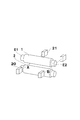
- FIG. 5 is a diagram schematically showing an example of a method for measuring the roll gap G by measuring the displacement according to the rotation angle of the lower end of the peripheral surface of the upper roll 1 and the upper end of the peripheral surface of the lower roll 2.
- the light-projecting side measurement sensor 20 and the light-receiving side measurement sensor 21 of the roll gap measuring apparatus 200 have a position A (first position) and a position B (first position) respectively corresponding to both ends of the workpiece. 2)
- the roll gap G can be measured.
- This position A is a position closer to one end E1 than the other end E2 of the upper roll shaft 1a.
- the position B is a position closer to the other end E2 than the one end E1 of the upper roll shaft 1a.
- FIG. 6 shows an example (position A) of the relationship between the roll gap G and the rotation angle measured in step S3.
- FIG. 6A shows the relationship between the rotation angle of the upper roll 1 and the position of the lower end of the peripheral surface of the upper roll 1 (hereinafter referred to as upper roll runout data).
- FIG. 6B shows the relationship between the rotation angle of the lower roll 2 and the position of the upper end of the peripheral surface of the lower roll 2 (hereinafter referred to as lower roll runout data).
- FIG. 6C shows the relationship between the rotation angle of each roll and the roll gap G.
- the roll gap G is calculated as a value obtained by subtracting the displacement value at the upper end of the peripheral surface of the lower roll 2 from the displacement at the lower end of the peripheral surface of the upper roll 1.
- the “position” on the vertical axis in FIGS. 6A and 6B indicates the distance from the reference point set in the roll gap measuring apparatus 200.
- the upper roll runout data, the lower roll runout data, and the roll gap G are data for three roll rotations (angle 0-1080 °).
- the upper roll runout data and the lower roll runout data fluctuate according to the rotation angle, and are repeated with the same waveform in one rotation cycle (360 ° cycle).
- the roll gap G has a target value of 554 ⁇ m, whereas the roll gap G varies between 547 and 562 ⁇ m including the target value. Therefore, the fluctuation range indicating the gap accuracy is a large value of 15 ⁇ m.
- step S3 the same measurement is performed at position B.
- step S4 the positions of the one end E1 and the other end E2 of the upper roll shaft 1a are individually adjusted from the roll gap G corresponding to the rotation angle measured in step S3, and the top is increased according to the rotation angle.
- a correction value for controlling the position and posture of the roll 1 is calculated. That is, in step S4, two correction values are calculated: a correction value for controlling the position of the first upper roll bearing case 3a and a correction value for controlling the position of the second upper roll bearing case 3b.
- correction values are calculated so that the roll gap G falls within a predetermined fluctuation range with respect to the target value.
- these correction values are rotated by one rotation of the upper roll 1 so that the position control unit 14b of the control device 14 reduces the difference between the fluctuation value of the upper roll deflection data and the fluctuation value of the lower roll deflection data. It is calculated by adjusting the position of the upper roll bearing case 3 according to the angle.
- the correction value is calculated by measuring the distance coefficient set in consideration of the measurement data of the positions A and B and the geometric relationship such as the distance from the positions A and B to the upper roll bearing case 3 and the roll diameter. This is performed by multiplying the roll gap G.
- the interval for calculating the correction value is at least 360 points per 1 °. Details of the correction value calculation method in step S4 will be described later.
- step S5 based on the correction value obtained in step S4, the electric servo actuator 5 is driven to individually control the position of one set of the upper roll bearing case 3, and the position of the upper roll 1 according to the rotation angle.
- the roll gap G is measured while controlling the posture.
- FIG. 7 shows upper roll runout data (FIG. 7A), lower roll runout data (FIG. 7B), and roll when the position and orientation of the upper roll 1 measured at the same location as FIG. 6 are corrected. It is a gap G (FIG. 7C).
- the upper roll runout data follows the lower roll runout data according to the rotation angle.
- the roll gap G fluctuated between 553 and 555 ⁇ m including the target value with respect to the target value of 554 ⁇ m, and the fluctuation range was a very small value of 2 ⁇ m. From this result, it was confirmed that the gap accuracy of the roll gap G can be remarkably improved by adjusting the position of the upper roll bearing case 3.
- step S6 it is determined whether or not the gap accuracy is equal to or less than a desired value. If the gap accuracy is equal to or less than the desired value (step S6: YES), the process proceeds to step S7. If it exceeds (NO in Step S6), the process proceeds to Step S4, and Steps S4 and S5 are repeated until the gap accuracy becomes a desired value or less. In addition to the positions A and B, the gap accuracy may be determined by adding the gap accuracy at the center of the roll.
- step S7 operating conditions are set based on the correction value.
- This operating condition is based on the rotation angles of the first electric servo actuator 5a and the second electric servo actuator 5b for setting the vertical position of one end E1 and the other end E2 to the adjusted positions.
- the corresponding control amount is included.
- the above steps S4 to S7 correspond to a roll gap correction step for creating an operation condition for controlling the roll gap G so as to be within a predetermined fluctuation range with respect to the target value.
- the creation of the correction value in step S4 can be performed by the following procedure.
- the roll gap at the position B is measured, and the position of the second upper roll bearing case 3b closer to the position B is adjusted based on the measured roll gap G (second step, second control). .
- second step, second control the vertical position of the other end E2 of the upper roll shaft 1a is adjusted.
- these steps are repeatedly performed until an operation condition for obtaining a desired roll gap is obtained, that is, until the roll gap G measured at the position A and the position B falls within a predetermined fluctuation range with respect to the target value ( (3rd process, 3rd control). Thereby, it can be made to converge on a favorable correction value and driving
- the correction value in step S4 can be created by the following procedure.
- the roll gap G is simultaneously measured at the position A and the position B (first step, first control). Based on the roll gap G measured at the position A, the position of the first upper roll bearing case 3a is adjusted. Further, based on the roll gap G measured at the position B, the second upper roll bearing case 3b closer to the position B is adjusted (second step, second control). Thereby, based on the roll gap in position A and position B, the position of the up-down direction of one end E1 and other end E2 of upper roll axis 1a is adjusted, respectively. Thereafter, the roll gap G is measured again at the positions A and B.
- step S8 based on the operating conditions set in step S7, the position of the pair of upper roll bearing cases 3 is individually adjusted, and the upper roll 1 and the lower roll whose positions and postures are adjusted according to the rotation angle. 2 is used to pressurize the workpiece.
- one roll gap measuring device 200 may measure a plurality of roll gaps G, or two sets of the light emitting side measurement sensor 20 and the light receiving side measurement sensor 21 are provided. It is also possible to prepare and perform a roll gap measuring apparatus 200 configured to be capable of simultaneously measuring the roll gap. A plurality of roll gap measuring devices 200 may be prepared. Further, the roll gap measuring device 200 may be disposed in the roll type pressurizing device 100, or may be disposed only when measuring the roll gap G.
- an optical sensor is used as the roll gap measuring apparatus 200, but the present invention is not limited to this.
- the roll gap measuring apparatus 200 may include other sensors such as a capacitive displacement sensor, an eddy current displacement sensor, and a mechanical displacement sensor as sensors for measuring the roll gap.
- the roll gap G is calculated as a value obtained by subtracting the value of the displacement of the upper end of the peripheral surface of the lower roll 2 from the displacement of the lower end of the peripheral surface of the upper roll 1, but a configuration in which the roll gap G is directly measured may be adopted. it can.
- a method in which the pressure rolls are arranged vertically is adopted, but the present invention is not limited to this.
- a configuration in which rolls are arranged in parallel in the horizontal direction can be employed.
- position of the upper roll 1 were controlled, the structure which controls the position and attitude
- the roll gap G is measured at two positions A and B in the width direction of the upper roll 1, but the roll gap G is not necessarily measured at a plurality of positions. Instead, it may be measured at one or more positions.
- the position of 1 set of upper roll bearing cases 3 is adjusted individually by the adjustment mechanism, if the position along the up-down direction of the upper roll 1 can be adjusted, position will be adjusted by the adjustment mechanism.
- the object to be adjusted is not limited to one set of the upper roll bearing case 3.
- the reference position is set for each of the upper roll 1 and the lower roll 2, and the roll is measured while rotating the upper roll 1 and the lower roll 2 by the roll gap measuring step.
- the roll gap G is measured at two positions in the width direction, and the relationship between the rotation angle from the reference position and the roll gap G is acquired for at least one roll rotation, and the rotation angle from the reference position is obtained by the roll gap correction process.
- the position of the upper roll bearing case 3 is controlled according to the rotation angle, and the operation condition is created to control the roll gap G within a predetermined fluctuation range with respect to the target value.
- the pressurization process of a to-be-processed object can be performed based on an operating condition by a roll press process.
- the correction value reflecting all the influences of factors such as roll processing accuracy, bearing rotation accuracy, bearing assembly accuracy, and roll thermal deformation that affects the accuracy of the roll gap G in the actual pressurizing process is short and Since it is calculated
- it can be suitably used for pressure treatment in the laminating step of the multilayer functional film and the compression step of the battery material.
- the roll press system S can be configured to include a thickness measurement sensor that measures the thickness of the workpiece.
- FIG. 8 is a side view schematically showing a roll press system according to another embodiment.
- the roll press system includes a first thickness measurement sensor 15 and a second thickness measurement sensor 16.
- the first thickness measurement sensor 15 is provided on the upstream side in the conveyance direction of the object to be processed in the roll pressure device 100.
- the second thickness measurement sensor 16 is provided on the downstream side in the conveyance direction of the object to be processed in the roll-type pressure device 100.
- a known sensor having a desired measurement accuracy can be used.
- a reflective displacement meter using laser light as a light source is used.
- the master work whose thickness has been measured in advance is simultaneously measured by the first thickness measurement sensors 15 arranged above and below, and the thickness of the workpiece is measured.
- the difference from the data at the time of masterwork measurement is calculated, and the thickness is calculated.
- the object to be processed before the pressure treatment is W1, and the object to be treated after the pressure treatment is W2.
- the first thickness measurement sensor 15 measures the thickness of W1 and sends measurement data to the control device 14.
- the control device 14 calculates the target value of the roll gap G by adding the necessary pushing amount to the actually measured thickness.
- the distance from the roll-type pressure device 100 to W1 is grasped by a transport mechanism using a servo motor (not shown), and when W1 is subjected to pressure treatment between the upper roll 1 and the lower roll 2, It becomes possible to adjust the height of the upper roll 1 according to the measured thickness. Thereby, when it is desired to perform a process of crushing the workpiece by a certain thickness, it is possible to always crush the same amount. Thereby, a uniform pressure can be applied irrespective of the thickness of the workpiece before the pressure treatment.
- the second thickness measurement sensor 16 measures the thickness of W2 and sends measurement data to the control device 14.
- the control device 14 calculates a correction value in consideration of the difference, and performs control reflecting the re-correction value from the time of processing W1 to be input next. .
- the thickness of the to-be-processed object after a pressurization process can be made into the thickness of a setting value.
- the thickness of the workpiece can be measured and fed back to the operation condition. In addition to being excellent, the accuracy can be adjusted in a short time.
Landscapes
- Engineering & Computer Science (AREA)
- Mechanical Engineering (AREA)
- Manufacturing & Machinery (AREA)
- Casting Or Compression Moulding Of Plastics Or The Like (AREA)
- Press Drives And Press Lines (AREA)
- Length Measuring Devices By Optical Means (AREA)
- Presses And Accessory Devices Thereof (AREA)
- Battery Electrode And Active Subsutance (AREA)
Abstract
Description
・ロール径:150mm
・ロール長:180mm
・測定位置:ロール端から15mm
・ロール回転速度:2.67rpm
・データ取得間隔:1°毎
・目標ロールギャップ:554μm
以上、種々の実施形態に係るロールプレス方法及びロールプレスシステムについて説明してきたが、上述した実施形態に限定されることなく発明の要旨を変更しない範囲で種々の変形態様を構成可能である。例えば、一実施形態では、1台のロールギャップ測定装置200で複数箇所のロールギャップGの測定を行ってもよいし、投光側計測センサ20及び受光側計測センサ21を2組備え、2箇所のロールギャップを同時に測定可能に構成されたロールギャップ測定装置200を用意して行うこともできる。また、ロールギャップ測定装置200を複数台用意しても良い。また、ロールギャップ測定装置200は、ロール式加圧装置100に配設してもよいし、ロールギャップGの測定時のみ配置してもよい。
上記実施形態のロールプレス方法及びロールプレスシステムによれば、上ロール1及び下ロール2のそれぞれについて基準位置を設定し、ロールギャップ測定工程により、上ロール1及び下ロール2を回転させながら、ロールの幅方向の2つの位置において、ロールギャップGを測定し、基準位置からの回転角とロールギャップGとの関係を少なくともロール1回転分取得し、ロールギャップ補正工程により、基準位置からの回転角とロールギャップGとの関係に基づいて、回転角に応じて上ロールベアリングケース3の位置を制御し、ロールギャップGを目標値に対して所定の変動範囲に収まるように制御する運転条件を作成し、ロールプレス工程により、運転条件に基づいて、被処理物の加圧処理を行うことができる。これにより、実際の加圧処理でロールギャップGの精度に影響を及ぼすロール加工精度、ベアリング回転精度、ベアリング組付け精度、ロール熱変形等の諸因子の影響をすべて反映した補正値が短時間かつ精度よくロール全周にわたって求められ、その補正値に基づいて運転条件を設定することができるため、加圧処理された被処理物の厚さを均一にすることができる。特に、多層機能性フィルムのラミネート工程や電池材料の圧縮工程での加圧処理に好適に用いることができる。
ロールプレスシステムSは、被処理物の厚さを測定する厚さ計測センサを備えた構成とすることができる。
Claims (13)
- 被処理物を連続的に加圧処理するロール式加圧装置を用いたロールプレス方法であって、
前記ロール式加圧装置は、
互いに対向する第1のロール及び第2のロールと、
前記第1のロールと前記第2のロールとの対向方向に沿って前記第1のロールの位置を調整可能な調整機構と、
を備え、
前記ロールプレス方法は、
前記第1のロール及び前記第2のロールを回転させながら、前記第1のロールの幅方向における1以上の位置において前記第1のロールの外周面と第2のロールの外周面との間のロールギャップを測定し、測定された前記ロールギャップと前記第1のロール及び前記第2のロールの回転角とを関連付けて記憶するロールギャップ測定工程と、
前記ロールギャップが目標値に対して所定の変動範囲に収まるように、前記調整機構によって前記第1のロールの前記対向方向における位置を前記回転角に応じて調整し、前記回転角に応じて位置が調整された前記第1のロールと前記第2のロールとを用いて前記被処理物の加圧処理を行うロールプレス工程と、
を含む、ロールプレス方法。 - 前記ロールギャップ測定工程では、前記被処理物の幅方向の両端部に対応する位置において前記ロールギャップを測定する、請求項1に記載のロールプレス方法。
- 前記調整機構は、前記対向方向に平行な方向に沿って前記第1のロールの回転軸の一方の端部及び他方の端部の位置を個別に調整可能であり、
前記ロールギャップ測定工程は、
前記第1のロールの幅方向における第1の位置において前記ロールギャップを測定し、前記第1の位置で測定された前記ロールギャップに基づいて前記一方の端部の位置を調整する第1の工程であり、前記第1の位置は前記他方の端部よりも前記一方の端部に近い位置である、該第1の工程と、
前記第1の工程の後に、前記第1のロールの幅方向における第2の位置において前記ロールギャップを測定し、前記第2の位置で測定された前記ロールギャップに基づいて前記他方の端部の位置を調整する第2の工程であり、前記第2の位置は前記一方の端部よりも前記他方の端部に近い位置である、該第2の工程と、
前記第1の位置及び前記第2の位置における前記ロールギャップが目標値に対して所定の変動範囲に収まるまで前記第1の工程及び前記第2の工程を交互に繰り返し行う第3の工程と、
を含む、請求項1または請求項2に記載のロールプレス方法。 - 前記調整機構は、前記対向方向に平行な方向に沿って前記第1のロールの回転軸の一方の端部及び他方の端部の位置を個別に調整可能であり、
前記ロールギャップ測定工程は、
前記第1のロールの幅方向の第1の位置及び第2の位置において前記ロールギャップを同時に測定する第1の工程であり、前記第1の位置が前記他方の端部よりも前記一方の端部に近い位置であり、前記第2の位置が前記一方の端部よりも前記他方の端部に近い位置である、該第1の工程と、
前記第1の位置における前記ロールギャップに基づいて前記一方の端部の位置を調整するとともに、前記第2の位置における前記ロールギャップに基づいて前記他方の端部の位置を調整する第2の工程と、
前記第1の位置及び前記第2の位置における前記ロールギャップが目標値に対して所定の変動範囲に収まるまで前記第1の工程及び前記第2の工程を交互に繰り返し行う第3の工程と、
を含む、請求項1または請求項2に記載のロールプレス方法。 - 前記ロールギャップ測定工程では、ロールギャップ測定装置を用いて前記ロールギャップを測定し、
前記ロールギャップ測定装置は、
前記第1のロールと前記第2のロールとの間の隙間に対し光を照射する投光側計測センサと、
前記隙間を通過した光を受光し、受光した光の幅を検出する受光側計測センサと、
を備え、
前記ロールギャップ測定工程では、前記受光側計測センサにおいて検出された光の幅からロールギャップを測定する、請求項1~4のいずれか一項に記載のロールプレス方法。 - 加圧処理前および/または加圧処理後の前記被処理物の厚さを測定する厚さ測定工程を更に含む、請求項1~5のいずれか一項に記載のロールプレス方法。
- ロール式加圧装置と、ロールギャップ測定装置とを備えるロールプレスシステムであって、
前記ロール式加圧装置は、
互いに対向する第1のロール及び第2のロールと、
前記第1のロールと前記第2のロールとの対向方向に沿って前記第1のロールの位置を調整可能な調整機構と、
制御装置と、
を含み、
前記ロールギャップ測定装置は、前記第1のロール及び第2のロールを回転させながら、前記第1のロールの幅方向における1以上の位置において前記第1のロールの外周面と第2のロールの外周面との間のロールギャップを測定可能に構成され、
前記制御装置は、
前記ロールギャップ測定装置によって測定された前記ロールギャップと前記第1のロール及び前記第2のロールの回転角とを関連付けて記憶する記憶部と、
前記ロールギャップが目標値に対して所定の変動範囲に収まるように、前記調整機構によって前記第1のロールの前記対向方向における位置を前記回転角に応じて調整する位置制御部と、
を含む、ロールプレスシステム。 - 前記調整機構は、電動サーボアクチュエータを用いた調整機構である、請求項7に記載のロールプレスシステム。
- 前記調整機構は、前記対向方向に平行な方向に沿って前記第1のロールの回転軸の一方の端部及び他方の端部の位置を個別に調整可能である、請求項7又は8に記載のロールプレスシステム。
- 前記制御装置は、
前記ロールギャップ測定装置によって測定された前記第1のロールの幅方向の第1の位置における前記ロールギャップに基づいて前記一方の端部の位置が調整されるように前記調整機構を制御する第1の制御であり、前記第1の位置は前記他方の端部よりも前記一方の端部に近い位置である、該第1の制御と、
前記ロールギャップ測定装置によって測定された前記第1のロールの幅方向の第2の位置における前記ロールギャップに基づいて前記他方の端部の位置が調整されるように前記調整機構を制御する第2の制御であり、前記第2の位置は前記一方の端部よりも前記他方の端部に近い位置である、該第2の制御と、
前記第1の位置及び前記第2の位置における前記ロールギャップが目標値に対して所定の変動範囲に収まるまで前記第1の制御及び前記第2の制御を交互に繰り返し行う第3の制御と、
を行う、請求項9に記載のロールプレスシステム。 - 前記制御装置は、
前記ロールギャップ測定装置によって同時に測定された前記第1のロールの幅方向の第1の位置及び第2の位置における前記ロールギャップを前記ロールギャップ測定装置から受け取る第1の制御であり、前記第1の位置が前記他方の端部よりも前記一方の端部に近い位置であり、前記第2の位置が前記一方の端部よりも前記他方の端部に近い位置である、該第1の制御と、
前記第1の位置における前記ロールギャップに基づいて前記一方の端部の位置が調整され、前記第2の位置における前記ロールギャップに基づいて前記他方の端部の位置が調整されるように前記調整機構を制御する第2の制御と、
前記第1の位置及び前記第2の位置における前記ロールギャップが目標値に対して所定の変動範囲に収まるまで前記第1の制御及び前記第2の制御を交互に繰り返し行う第3の制御と、
を行う、請求項9に記載のロールプレスシステム。 - 前記第1のロール及び第2のロールは、サーボモータにより回転駆動する、請求項7~11のいずれか一項に記載のロールプレスシステム。
- 加圧処理前および/または加圧処理後の被処理物の厚さを測定する厚さ測定装置を更に備える、請求項7~12のいずれか一項に記載のロールプレスシステム。
Priority Applications (5)
| Application Number | Priority Date | Filing Date | Title |
|---|---|---|---|
| US16/318,472 US10933616B2 (en) | 2016-08-01 | 2017-05-26 | Roll press method and roll press system |
| KR1020177023817A KR20190034483A (ko) | 2016-08-01 | 2017-05-26 | 롤 프레스 방법 및 롤 프레스 시스템 |
| JP2018531751A JP6753467B2 (ja) | 2016-08-01 | 2017-05-26 | ロールプレス方法及びロールプレスシステム |
| CN201780047536.0A CN109562586B (zh) | 2016-08-01 | 2017-05-26 | 辊压方法和辊压系统 |
| EP17836583.9A EP3441217A4 (en) | 2016-08-01 | 2017-05-26 | ROLL PRESSING METHOD AND ROLL PRESSING SYSTEM |
Applications Claiming Priority (2)
| Application Number | Priority Date | Filing Date | Title |
|---|---|---|---|
| JP2016150943 | 2016-08-01 | ||
| JP2016-150943 | 2016-08-01 |
Publications (1)
| Publication Number | Publication Date |
|---|---|
| WO2018025476A1 true WO2018025476A1 (ja) | 2018-02-08 |
Family
ID=60951046
Family Applications (1)
| Application Number | Title | Priority Date | Filing Date |
|---|---|---|---|
| PCT/JP2017/019774 Ceased WO2018025476A1 (ja) | 2016-08-01 | 2017-05-26 | ロールプレス方法及びロールプレスシステム |
Country Status (8)
| Country | Link |
|---|---|
| US (1) | US10933616B2 (ja) |
| EP (1) | EP3441217A4 (ja) |
| JP (1) | JP6753467B2 (ja) |
| KR (1) | KR20190034483A (ja) |
| CN (1) | CN109562586B (ja) |
| DE (1) | DE102017212832A1 (ja) |
| TW (1) | TWI711497B (ja) |
| WO (1) | WO2018025476A1 (ja) |
Cited By (2)
| Publication number | Priority date | Publication date | Assignee | Title |
|---|---|---|---|---|
| JP2018058113A (ja) * | 2016-10-06 | 2018-04-12 | ユースエンジニアリング株式会社 | ロールプレス装置 |
| JP2022074390A (ja) * | 2020-11-04 | 2022-05-18 | トヨタ自動車株式会社 | プレスロール装置、及びプレスロール装置の制御方法 |
Families Citing this family (20)
| Publication number | Priority date | Publication date | Assignee | Title |
|---|---|---|---|---|
| EP3354433A1 (de) * | 2017-01-31 | 2018-08-01 | Covestro Deutschland AG | Vorrichtung mit freilaufenden kühlwalzen zur herstellung eines faserverbundwerkstoffs in form eines mit polymer imprägnierten faserbands, verfahren zur herstellung dieses faserbands, ein imprägniertes faserband und ein aus dem imprägnierten faserband hergestellter mehrschichtverbund |
| JP7557790B2 (ja) * | 2020-01-09 | 2024-09-30 | パナソニックIpマネジメント株式会社 | ロールプレス装置、及び制御装置 |
| CN112846477B (zh) * | 2020-12-29 | 2022-06-28 | 瓯锟科技温州有限公司 | 一种用于粉末和金属板复合的装置 |
| CN112959725B (zh) * | 2021-02-02 | 2022-09-06 | 上海神力科技有限公司 | 一种燃料电池柔性石墨极板的辊压成型方法 |
| TWI772143B (zh) * | 2021-08-12 | 2022-07-21 | 大陸商常州欣盛半導體技術股份有限公司 | 高精度送膜裝置的使用方法 |
| KR20230045125A (ko) | 2021-09-28 | 2023-04-04 | 주식회사 엘지에너지솔루션 | 롤갭 측정 시스템 및 롤갭 측정 방법 |
| TWI788150B (zh) * | 2021-12-20 | 2022-12-21 | 中國鋼鐵股份有限公司 | 軋輥彈張量的量測方法 |
| CN114407172A (zh) * | 2022-01-14 | 2022-04-29 | 移动源特种纤维(河南)有限公司 | 一种衬垫成型厚度自适应调节装置及其控制方法 |
| CN114623774A (zh) * | 2022-03-14 | 2022-06-14 | 上海华方巨量半导体科技有限公司 | 用于微型组件转移的来源基板与接收基板的间隙测量方法 |
| CN115020648B (zh) * | 2022-04-21 | 2024-04-19 | 深圳吉阳智能科技有限公司 | 极片复合装置和极片复合方法 |
| CN115352090A (zh) * | 2022-08-17 | 2022-11-18 | 常州赛瑞工程技术有限公司 | 浸润压合装置 |
| CN115431560A (zh) * | 2022-09-02 | 2022-12-06 | 常州赛瑞工程技术有限公司 | 一种浸润压合机构 |
| DE102023108128A1 (de) * | 2023-03-30 | 2024-10-02 | Bayerische Motoren Werke Aktiengesellschaft | Verfahren und vorrichtung zum abtrennen eines aktivmaterials von einem stromableiter |
| CN116441331A (zh) * | 2023-05-12 | 2023-07-18 | 广东中南钢铁股份有限公司 | 脱头辊道出口夹送辊的方法 |
| CN116638810B (zh) * | 2023-05-17 | 2026-03-17 | 合肥水泥研究设计院有限公司 | 一种自动调节原始辊缝的辊压机及其原始辊缝调节方法 |
| WO2025053707A1 (ko) * | 2023-09-07 | 2025-03-13 | 주식회사 엘지에너지솔루션 | 전극의 제조방법 및 제조장치 |
| KR102845972B1 (ko) * | 2023-09-07 | 2025-08-13 | 주식회사 엘지에너지솔루션 | 전극의 제조방법 및 제조장치 |
| CN117325303A (zh) * | 2023-10-16 | 2024-01-02 | 中材国际智能科技有限公司 | 一种智能化辊压机控料控压系统 |
| US20250149535A1 (en) * | 2023-11-07 | 2025-05-08 | Honeywell International Inc. | Battery Electrode Manufacturing Advanced Calender Measurement and Control |
| KR20260034381A (ko) * | 2024-09-04 | 2026-03-11 | 한국기계연구원 | 롤 프레싱 공정에서 롤러 갭 측정 시스템 및 이를 이용한 롤러 갭 측정방법 |
Citations (9)
| Publication number | Priority date | Publication date | Assignee | Title |
|---|---|---|---|---|
| JPS5533831A (en) * | 1978-08-31 | 1980-03-10 | Toshiba Corp | Roll eccentricity removing method |
| JPS5945016A (ja) * | 1982-09-08 | 1984-03-13 | Sumitomo Metal Ind Ltd | 圧延機の板厚制御方法 |
| JPS63117204A (ja) * | 1986-11-06 | 1988-05-21 | Mitsubishi Heavy Ind Ltd | ロ−ルのギヤツプ検出装置 |
| JPH0465163U (ja) * | 1990-10-15 | 1992-06-05 | ||
| JP2007030337A (ja) | 2005-07-27 | 2007-02-08 | Hitachi Engineering & Services Co Ltd | 金属箔樹脂フィルム積層板製造装置 |
| JP2007090396A (ja) * | 2005-09-29 | 2007-04-12 | Mitsubishi Paper Mills Ltd | 圧着フォーム作成装置 |
| JP2013111647A (ja) | 2011-12-01 | 2013-06-10 | Hitachi Engineering & Services Co Ltd | ロールプレス設備 |
| JP2014173996A (ja) | 2013-03-08 | 2014-09-22 | Hitachi Power Solutions Co Ltd | ロールプレス設備に用いられるロールの形状測定方法およびロールプレス設備用ロール形状測定装置 |
| JP2016112872A (ja) * | 2014-12-18 | 2016-06-23 | トヨタ自動車株式会社 | 圧延装置、圧延装置のギャップ調整方法 |
Family Cites Families (13)
| Publication number | Priority date | Publication date | Assignee | Title |
|---|---|---|---|---|
| JPS5828568B2 (ja) * | 1978-09-25 | 1983-06-16 | 富士写真フイルム株式会社 | ハロゲン化銀写真乳剤 |
| JPS55153606A (en) * | 1979-05-15 | 1980-11-29 | Mitsubishi Heavy Ind Ltd | Rolling mill for sheet material |
| JPS59191555A (ja) * | 1983-04-15 | 1984-10-30 | Sanpa Kogyo Kk | 連鋳機のロ−ルギヤツプ測定装置 |
| JPH05317945A (ja) | 1992-05-14 | 1993-12-03 | Kawasaki Steel Corp | 連続圧延機の板厚制御方法および装置 |
| DE19518879A1 (de) * | 1995-05-28 | 1996-12-05 | Dieffenbacher Gmbh Maschf | Verfahren und Anlage zur Herstellung von Spanplatten |
| JPH10208568A (ja) * | 1997-01-24 | 1998-08-07 | Fujikura Ltd | テープ電線の製造装置 |
| US6568285B1 (en) * | 1998-02-19 | 2003-05-27 | Stowe Woodward Llc | Nip width sensing system and method |
| JP2000063909A (ja) * | 1998-08-14 | 2000-02-29 | Ishikawajima Harima Heavy Ind Co Ltd | 粉末圧延機 |
| JP4492984B2 (ja) * | 1999-07-22 | 2010-06-30 | 株式会社アマダ | パネルベンダ |
| US6860030B1 (en) * | 2000-11-15 | 2005-03-01 | Voith Paper, Inc. | Control system for gap measuring |
| CN101239358B (zh) | 2008-03-06 | 2010-06-30 | 张明 | 双辊铸轧—热连轧方法及设备 |
| EP2644288B1 (en) * | 2010-11-22 | 2017-01-04 | Toshiba Mitsubishi-Electric Industrial Systems Corporation | Rolling mill control device |
| JP5589152B1 (ja) * | 2014-06-02 | 2014-09-17 | 新日鉄住金エンジニアリング株式会社 | ロール圧下装置 |
-
2017
- 2017-05-26 CN CN201780047536.0A patent/CN109562586B/zh active Active
- 2017-05-26 JP JP2018531751A patent/JP6753467B2/ja active Active
- 2017-05-26 EP EP17836583.9A patent/EP3441217A4/en not_active Withdrawn
- 2017-05-26 KR KR1020177023817A patent/KR20190034483A/ko not_active Ceased
- 2017-05-26 WO PCT/JP2017/019774 patent/WO2018025476A1/ja not_active Ceased
- 2017-05-26 US US16/318,472 patent/US10933616B2/en active Active
- 2017-07-26 DE DE102017212832.1A patent/DE102017212832A1/de active Pending
- 2017-07-26 TW TW106125063A patent/TWI711497B/zh active
Patent Citations (9)
| Publication number | Priority date | Publication date | Assignee | Title |
|---|---|---|---|---|
| JPS5533831A (en) * | 1978-08-31 | 1980-03-10 | Toshiba Corp | Roll eccentricity removing method |
| JPS5945016A (ja) * | 1982-09-08 | 1984-03-13 | Sumitomo Metal Ind Ltd | 圧延機の板厚制御方法 |
| JPS63117204A (ja) * | 1986-11-06 | 1988-05-21 | Mitsubishi Heavy Ind Ltd | ロ−ルのギヤツプ検出装置 |
| JPH0465163U (ja) * | 1990-10-15 | 1992-06-05 | ||
| JP2007030337A (ja) | 2005-07-27 | 2007-02-08 | Hitachi Engineering & Services Co Ltd | 金属箔樹脂フィルム積層板製造装置 |
| JP2007090396A (ja) * | 2005-09-29 | 2007-04-12 | Mitsubishi Paper Mills Ltd | 圧着フォーム作成装置 |
| JP2013111647A (ja) | 2011-12-01 | 2013-06-10 | Hitachi Engineering & Services Co Ltd | ロールプレス設備 |
| JP2014173996A (ja) | 2013-03-08 | 2014-09-22 | Hitachi Power Solutions Co Ltd | ロールプレス設備に用いられるロールの形状測定方法およびロールプレス設備用ロール形状測定装置 |
| JP2016112872A (ja) * | 2014-12-18 | 2016-06-23 | トヨタ自動車株式会社 | 圧延装置、圧延装置のギャップ調整方法 |
Non-Patent Citations (1)
| Title |
|---|
| See also references of EP3441217A4 |
Cited By (3)
| Publication number | Priority date | Publication date | Assignee | Title |
|---|---|---|---|---|
| JP2018058113A (ja) * | 2016-10-06 | 2018-04-12 | ユースエンジニアリング株式会社 | ロールプレス装置 |
| JP2022074390A (ja) * | 2020-11-04 | 2022-05-18 | トヨタ自動車株式会社 | プレスロール装置、及びプレスロール装置の制御方法 |
| JP7420052B2 (ja) | 2020-11-04 | 2024-01-23 | トヨタ自動車株式会社 | プレスロール装置、及びプレスロール装置の制御方法 |
Also Published As
| Publication number | Publication date |
|---|---|
| TW201805082A (zh) | 2018-02-16 |
| CN109562586A (zh) | 2019-04-02 |
| KR20190034483A (ko) | 2019-04-02 |
| CN109562586B (zh) | 2021-02-09 |
| US10933616B2 (en) | 2021-03-02 |
| DE102017212832A1 (de) | 2018-02-01 |
| JPWO2018025476A1 (ja) | 2019-05-30 |
| EP3441217A1 (en) | 2019-02-13 |
| US20190152210A1 (en) | 2019-05-23 |
| JP6753467B2 (ja) | 2020-09-09 |
| EP3441217A4 (en) | 2020-01-01 |
| TWI711497B (zh) | 2020-12-01 |
Similar Documents
| Publication | Publication Date | Title |
|---|---|---|
| JP6753467B2 (ja) | ロールプレス方法及びロールプレスシステム | |
| JP6489560B2 (ja) | ロールプレス機及びロールプレス機によるロールプレス方法 | |
| EP3412383B1 (en) | Apparatus for additive manufacturing of a product with a calibration device and method for calibration of an apparatus of this kind | |
| JP7115925B2 (ja) | インプリント装置及びこれを用いたインプリント方法 | |
| WO1997039903A1 (en) | Laminated object manufacturing system | |
| CN103221198A (zh) | 用于制造纤维复合材料构件的方法和制造单元 | |
| US20150239181A1 (en) | Machine for winding a fibrous material enabling alignment and off-centering control by image analysis | |
| JP5785918B2 (ja) | 加熱ロール及びロールプレス機、ロールプレス方法 | |
| JP5597420B2 (ja) | シート状モールド移送位置決め装置 | |
| CN105911070A (zh) | 涂布视觉检测控制装置及其检测控制方法 | |
| JP2021100802A (ja) | 積層システムおよび積層システムの制御方法 | |
| EP4302912A1 (en) | Additive manufacturing system and method for compression of material during material deposition | |
| US20200247035A1 (en) | Impact forming of thermoplastic composites | |
| US20120160165A1 (en) | Apparatus for manufacturing a thin film laminate | |
| JP5591025B2 (ja) | 心出し方法および心出し装置、レンズ心取り方法、レンズ心取り装置、枠切削方法および枠切削装置 | |
| JP7420052B2 (ja) | プレスロール装置、及びプレスロール装置の制御方法 | |
| KR20230111733A (ko) | 가변 가압 시스템을 갖는 3d 프린터 | |
| WO2005025849A1 (ja) | 加圧加熱装置 | |
| JP2013223871A (ja) | ロール装置 | |
| KR20110130671A (ko) | 슬라브 측정장치 | |
| CN106843142A (zh) | 基于板料成形过程的随动闭环控制系统及方法 | |
| JP2008216215A (ja) | シート状物湾曲測定装置およびシート状物湾曲測定方法 | |
| CN120363478B (zh) | 一种膜材料层压机 | |
| RU2646517C1 (ru) | Установка для диффузионной сварки | |
| EP4302913A1 (en) | Additive manufacturing system and method for compression of material based on detected temperature |
Legal Events
| Date | Code | Title | Description |
|---|---|---|---|
| ENP | Entry into the national phase |
Ref document number: 20177023817 Country of ref document: KR Kind code of ref document: A |
|
| ENP | Entry into the national phase |
Ref document number: 2018531751 Country of ref document: JP Kind code of ref document: A |
|
| WWE | Wipo information: entry into national phase |
Ref document number: 2017836583 Country of ref document: EP |
|
| ENP | Entry into the national phase |
Ref document number: 2017836583 Country of ref document: EP Effective date: 20181108 |
|
| 121 | Ep: the epo has been informed by wipo that ep was designated in this application |
Ref document number: 17836583 Country of ref document: EP Kind code of ref document: A1 |
|
| NENP | Non-entry into the national phase |
Ref country code: DE |