WO2018038100A1 - Climatiseur - Google Patents
Climatiseur Download PDFInfo
- Publication number
- WO2018038100A1 WO2018038100A1 PCT/JP2017/029931 JP2017029931W WO2018038100A1 WO 2018038100 A1 WO2018038100 A1 WO 2018038100A1 JP 2017029931 W JP2017029931 W JP 2017029931W WO 2018038100 A1 WO2018038100 A1 WO 2018038100A1
- Authority
- WO
- WIPO (PCT)
- Prior art keywords
- air
- indoor unit
- pillar
- support frame
- frame element
- Prior art date
- Legal status (The legal status is an assumption and is not a legal conclusion. Google has not performed a legal analysis and makes no representation as to the accuracy of the status listed.)
- Ceased
Links
Images






Classifications
-
- F—MECHANICAL ENGINEERING; LIGHTING; HEATING; WEAPONS; BLASTING
- F24—HEATING; RANGES; VENTILATING
- F24F—AIR-CONDITIONING; AIR-HUMIDIFICATION; VENTILATION; USE OF AIR CURRENTS FOR SCREENING
- F24F13/00—Details common to, or for air-conditioning, air-humidification, ventilation or use of air currents for screening
- F24F13/28—Arrangement or mounting of filters
-
- F—MECHANICAL ENGINEERING; LIGHTING; HEATING; WEAPONS; BLASTING
- F24—HEATING; RANGES; VENTILATING
- F24F—AIR-CONDITIONING; AIR-HUMIDIFICATION; VENTILATION; USE OF AIR CURRENTS FOR SCREENING
- F24F13/00—Details common to, or for air-conditioning, air-humidification, ventilation or use of air currents for screening
- F24F13/32—Supports for air-conditioning, air-humidification or ventilation units
Definitions
- Embodiment of this invention is related with the air conditioning apparatus provided with the indoor unit suitable for spot air conditioning, for example.
- an air conditioner that locally cools and heats a plurality of work areas dispersed in the factory building is used.
- This type of air conditioner includes a plurality of indoor units that blow out air whose temperature and humidity are adjusted toward a work area.
- the indoor unit is installed in the work area using, for example, a pillar that is a skeleton of a building.
- an air conditioner in which a dedicated frame is used to support the indoor unit.
- the frame is fixed to the outer periphery of the column in a form surrounding the column.
- the pillars located in the work area are often equipped with various devices such as switchboards, lighting fixtures or fire hydrants. Therefore, it becomes difficult to assemble a frame that supports the indoor unit to the column to which the devices are attached because the devices are in the way.
- An object of the present invention is to obtain an air-conditioning apparatus with improved flexibility in installing an indoor unit in a foundation structure and excellent versatility.
- the air conditioner includes a support frame and at least one indoor unit.
- the support frame is attached to at least one surface of a foundation structure having a plurality of surfaces.
- the indoor unit includes a heat exchanger and a blower for exchanging heat between the refrigerant and the air, and is removably supported by the support frame.
- FIG. 1 is a circuit diagram illustrating a piping system of the air-conditioning apparatus according to the first embodiment.
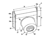
- FIG. 2 is a perspective view of the indoor unit used in the first embodiment viewed from the front.
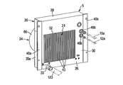
- FIG. 3 is a perspective view of the indoor unit as viewed from the back.
- FIG. 4 is an exploded perspective view showing the internal structure of the indoor unit.
- FIG. 5 is a front view of the indoor unit.
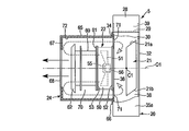
- FIG. 6 is a cross-sectional view of the indoor unit showing a flow direction of air blown from the indoor unit.
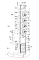
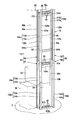
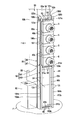
- FIG. 7 is a perspective view showing a state in which the indoor unit assembly is installed on a pillar in the first embodiment.
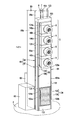
- FIG. 8 is a perspective view showing a state in which the support frame is fixed to the pillar of the building in the first embodiment.
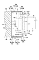
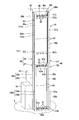
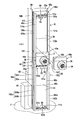
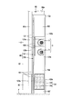
- FIG. 9 is a cross-sectional view illustrating a state where an indoor unit is installed on a pillar of a building via a support frame in the first embodiment.
- FIG. 10 is a perspective view showing a state in which the lower structure of the first frame element is fixed to the pillar of the building in the first embodiment.
- FIG. 11 is a perspective view illustrating a state in which the lower structure and the upper structure of the first frame element are fixed to the pillar of the building in the first embodiment.
- FIG. 12 is a perspective view showing a state in which the second frame element is coupled to the first frame element of the support frame in the first embodiment.
- FIG. 13 is a perspective view showing a process of attaching a plurality of indoor units to the upper structure of the second frame element one by one in the first embodiment.
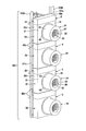
- FIG. 14 is a perspective view showing a state in which four indoor units are arranged in a line and attached to the upper structure of the second frame element in the first embodiment.
- FIG. 15 is a perspective view showing a state in which four indoor units are arranged in a line and attached to the upper structure of the second frame element in the second embodiment.
- FIG. 16 is a perspective view showing a state in which the upper structure of the second frame element to which the four indoor units are attached is assembled to the first frame element fixed to the pillar in the second embodiment.
- FIG. 17 is a perspective view showing a state in which a support frame to which four indoor units and a plurality of side panels are attached is fixed to a pillar in the third embodiment.
- FIG. 18 is a perspective view showing a state in which a support frame to which four indoor units and a plurality of side panels are attached is fixed to a pillar in the third embodiment.
- FIG. 19 is a perspective view showing a state in which the indoor unit assembly is installed on a pillar in the third embodiment.
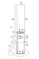
- FIG. 20 is a perspective view showing a state in which the indoor unit assembly is installed on a pillar in the fourth embodiment.
- FIG. 21 is a circuit diagram illustrating a piping system of an air conditioner according to the fifth embodiment.
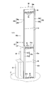
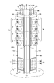
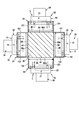
- FIG. 22 is a perspective view showing a state in which the first to fourth indoor unit assemblies are installed on the pillars in the fifth embodiment.
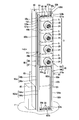
- FIG. 23 is a cross-sectional view showing a state in which the first to fourth indoor unit assemblies are installed on the pillars via the support frames in the fifth embodiment.
- FIG. 1 is a circuit diagram showing a piping system of an air conditioner 1 used for local cooling and heating in a large-scale space such as a production factory or a vehicle factory.
- the air conditioner 1 includes an outdoor unit 2 and an indoor unit assembly 3 as main elements.
- the outdoor unit 2 is installed outside the factory building 4 and houses various refrigeration cycle devices such as a compressor that compresses refrigerant, a heat exchanger, and an accumulator.
- the indoor unit assembly 3 is installed in a work area A inside the building 4.
- the work area A is an example of a space to be air-conditioned.
- the indoor unit assembly 3 includes, for example, four indoor units 5.
- Liquid pipe 7 and gas pipe 8 are connected to the outdoor unit 2.
- the liquid pipe 7 and the gas pipe 8 are led to the indoor unit assembly 3, respectively.
- the liquid pipe 7 has four liquid pipes 10a, 10b, 10c, 10d branched by three Y-shaped branch joints 9a, 9b, 9c.
- the liquid pipes 10a, 10b, 10c, and 10d are connected to the indoor unit 5, respectively.
- the gas pipe 8 has four gas pipes 12a, 12b, 12c, and 12d branched by three T-shaped branch joints 11a, 11b, and 11c.
- the gas pipes 12a, 12b, 12c, and 12d are connected to the indoor unit 5, respectively.
- the refrigerant compressed by the outdoor unit 2 is distributed to the indoor unit 5 of the indoor unit assembly 3, and the refrigerant discharged from the indoor unit 5 is returned to the outdoor unit 2 again.
- the indoor unit assembly 3 includes a remote controller 13.
- various operations such as operation / stop of the indoor unit 5, temperature setting, and operation switching can be performed by the remote controller 13.
- the four indoor units 5 included in the indoor unit assembly 3 have a common configuration. Therefore, in the present embodiment, one indoor unit 5 will be described as a representative.
- the indoor unit 5 includes a housing 20, an air heat exchanger 21, a blower 22, a control unit 23, and a duct unit 24 as main elements.
- casing 20 is a square box-shaped element which has the depth dimension D, the width dimension W, and the height dimension H, Comprising: For example, it is formed with the thin steel plate.
- the width dimension W and the height dimension H of the housing 20 are equal to each other, and the depth dimension D is set to be much smaller than the width dimension W and the height dimension H. Therefore, the housing 20 has a flat shape.
- the housing 20 includes a base 26, a front cover 27, a top cover 28, and a partition plate 29.
- the base 26 includes a back panel 30 that is erected and a dish-shaped bottom plate 31 that is fixed to the lower end of the back panel 30.
- a square suction port 32 is formed at a substantially central portion of the back panel 30.
- the bottom plate 31 protrudes horizontally from the lower end of the back panel 30 toward the front of the housing 20.
- a drain port 33 is formed at the rear end of the bottom plate 31. The drain port 33 protrudes behind the housing 20.
- the front cover 27 includes a front panel 34 and a pair of side panels 35a and 35b.
- the front panel 34 is an element constituting the front surface of the housing 20.
- the front panel 34 faces the back panel 30, and a through hole 36 is formed at a substantially central portion of the front panel 34. Further, the lower end portion of the front panel 34 is fixed to the front end portion of the bottom plate 31 with a plurality of screws.
- the side panels 35a and 35b extend from the side edge of the front panel 34 toward the back panel 30 at an angle of 90 °.
- the rear ends of the side panels 35a and 35b are fixed to both sides of the back panel 30 with a plurality of screws.
- the top cover 28 is fixed to the upper end portion of the front panel 34 and the upper end portions of the side panels 35a and 35b with a plurality of screws.
- the top cover 28 covers a gap between the upper end portion of the front cover 27 and the upper portion of the back panel 30.
- the partition plate 29 is interposed between the upper part of the back panel 30 and the upper end part of the front cover 27.
- the partition plate 29 divides the interior of the housing 20 into two chambers, a first storage chamber 38 and a second storage chamber 39.
- the first storage chamber 38 has a larger volume than the second storage chamber 39, and the suction port 32 and the through hole 36 of the housing 20 are opened in the first storage chamber 38.
- the bottom plate 31 of the housing 20 constitutes the bottom of the first storage chamber 38, and the bottom plate 31 also functions as a drain pan.
- the second storage chamber 39 is located above the first storage chamber 38 and is covered with the top cover 28. In other words, the second storage chamber 39 can be exposed outside the housing 20 by loosening the screw and removing only the top cover 28.
- brackets 40a and 40b are fixed to both sides of the back panel 30, respectively.
- the brackets 40 a and 40 b extend in the height direction of the housing 20 and project to the side of the housing 20.
- the air heat exchanger 21 is accommodated in the first accommodating chamber 38.
- the air heat exchanger 21 has a flat plate shape and includes a plurality of cooling fins 43 and a plurality of heat transfer tubes 44 through which refrigerant flows.
- the cooling fins 43 are elongated rectangular plates extending in the height direction of the housing 20, and are arranged in a line at intervals in the width direction of the housing 20.
- the heat transfer tubes 44 are arranged at intervals in the height direction and depth direction of the housing 20 and are connected in series to form a plurality of flow paths (paths). Further, the heat transfer tubes 44 are thermally connected to the cooling fins 43.
- the air heat exchanger 21 is erected along the back panel 30 inside the first storage chamber 38. As a result, the air heat exchanger 21 is exposed behind the housing 20 through the suction port 32.
- the air heat exchanger 21 has an upper end surface 21a and a lower end surface 21b.
- the upper end surface 21 a faces the partition plate 29 inside the first storage chamber 38.
- the lower end surface 21b is covered from below by a bottom plate 31 as a drain pan.
- the upper end surface 21a and the lower end surface 21b of the air heat exchanger 21 are inclined downward as they proceed from the back panel 30 toward the front panel 34, respectively.
- the refrigerant pipe 45 connected to the air heat exchanger 21 is accommodated in the first accommodating chamber 38.
- the air heat exchanger 21 is disposed between the side panels 35a and 35b of the front cover 27 on the side of one side panel 35a in order to secure a space for accommodating the refrigerant pipe 45 inside the first storage chamber 38. I'm leaning on. As a result, a space is generated between the air heat exchanger 21 and the other side panel 35b, and the refrigerant pipes 45 are concentrated in the space.
- the indoor unit 5 has a pair of connection ports 46 a and 46 b connected to the refrigerant pipe 45.
- the connection ports 46a and 46b penetrate the back panel 30 and protrude behind the housing 20, and the liquid pipe 10a and the gas pipe 12a are connected to the connection ports 46a and 46b.
- the center C1 of the air heat exchanger 21 is shifted to the center C2 of the front panel 34 of the front cover 27 as the air heat exchanger 21 is shifted toward the one side panel 35a. Is shifted to the side.
- the center of the through hole 36 opened in the front panel 34 is located on the extension line of the center C1 of the air heat exchanger 21.
- the blower 22 is supported at the center of the front panel 34 of the housing 20.
- the blower 22 includes a cylindrical casing 50 and an impeller 51 accommodated in the casing 50 as main elements.
- the casing 50 has a first flange portion 52 and a second flange portion 53.
- the first flange portion 52 projects outward at one end of the casing 50 along the radial direction of the casing 50.
- the second flange portion 53 projects outward at the other end of the casing 50 along the radial direction of the casing 50.
- the first flange portion 52 is fixed to the front panel 34 with a plurality of screws at a position corresponding to the through hole 36.
- the impeller 51 is rotatably supported by the casing 50 so as to be coaxially positioned on the extension line of the center C1 of the air heat exchanger 21.
- the boss portion 55 of the impeller 51 incorporates a motor 56 that rotates the impeller 51.
- the control unit 23 is an element for controlling the air heat exchanger 21 and the blower 22, and is accommodated in the second accommodation chamber 39 of the housing 20.
- the control unit 23 includes various electrical components 58 such as a control board, a reactor, and a plurality of terminal blocks.
- the electrical component 58 is supported on the upper portion of the back panel 30.
- a cylindrical attachment 60 is attached to the blower 22.
- the attachment 60 has a flange portion 61 at one end.
- the flange portion 61 is fixed to the second flange portion 53 of the blower 22 with a plurality of screws. Thereby, the attachment 60 protrudes coaxially from the casing 50 of the blower 22 toward the front of the housing 20.
- a cylindrical ventilation register 62 is fitted in the attachment 60.
- the ventilation register 62 is an element for adjusting the amount of air blown from the blower 22 or arbitrarily changing the blowing direction, and protrudes coaxially from the attachment 60 toward the front of the housing 20. .
- the duct portion 24 has a cylindrical outer cylinder 65.
- the outer cylinder 65 is an element that continuously covers the blower 22, the attachment 60, and the ventilation register 62, and a flange portion 66 is formed at one end along the axial direction thereof.
- the flange portion 66 is continuous in the circumferential direction of the outer cylinder 65 and projects outwardly along the radial direction of the outer cylinder 65.
- the flange portion 66 is detachably supported on the front panel 34 by a plurality of screws.
- the outer cylinder 65 protrudes horizontally from the front panel 34 toward the front of the housing 20 in a state of surrounding the blower 22, the attachment 60, and the ventilation register 62. As shown in FIG. 6, the axis O ⁇ b> 1 passing through the center of the outer cylinder 65 passes through the center C ⁇ b> 1 of the air heat exchanger 21.
- the protruding end of the outer cylinder 65 is located in front of the housing 20 with respect to the ventilation register 62.
- a guide wall 67 is formed at the protruding end of the outer cylinder 65.
- the guide wall 67 is continuous in the circumferential direction of the outer cylinder 65 and protrudes toward the inside along the radial direction of the outer cylinder 65.
- the guide wall 67 defines a circular outlet 68 at the protruding end of the outer cylinder 65.
- the blowout port 68 faces the blower 22 through the ventilation register 62.
- the outer cylinder 65 of the duct portion 24 defines a ventilation path 70 between the blower 22, the attachment 60 and the ventilation register 62.
- One end of the ventilation path 70 reaches the front panel 34 of the housing 20.
- the other end of the ventilation path 70 is closed by a guide wall 67.
- a plurality of air return holes 71 are formed in the front panel 34 of the housing 20 facing one end of the ventilation path 70.
- the air return hole 71 is located around the blower 22 and is opened to the first storage chamber 38 of the housing 20. Therefore, one end of the ventilation path 70 is communicated with the upstream side of the blower 22.
- the inner surface of the outer cylinder 65 facing the ventilation path 70 and the inner surface of the guide wall 67 are covered with the heat insulating material 72.
- the indoor unit assembly 3 having four indoor units 5 is installed using a dedicated support frame 81 on the outer periphery of an existing column 80 that is a skeleton of the building 4.
- the pillar 80 is an example of a basic structure, and stands upright from the floor surface F of the building 4. According to this embodiment, the pillar 80 is a quadrangular pillar having the first to fourth surfaces 80a, 80b, 80c, and 80d.
- the first to fourth surfaces 80a, 80b, 80c, and 80d face the work area A in the building 4 and are oriented in four different directions.
- the first to fourth surfaces 80a, 80b, 80c, and 80d are basically flat surfaces having no unevenness, but there may be many holes or many dents.
- a fire hydrant 82 is disposed below the second surface 80b of the pillar 80. Further, a switchboard 83 is disposed below the third surface 80 c of the pillar 80. The fire hydrant 82 and the switchboard 83 project around the pillar 80, respectively.
- the support frame 81 is selectively attached to the lower part of the first surface 80a of the pillar 80 so as to avoid the fire hydrant 82 and the switchboard 83.
- a region where the support frame 81 is attached on the first surface 80 a of the column 80 is covered with a plurality of covers 84.
- Each cover 84 is formed of, for example, a square flat metal plate, and is arranged in a row so as to be continuous in the height direction of the pillar 80.
- the support frame 81 includes a first frame element 85 and a second frame element 86.
- the first frame element 85 is divided into a lower structure 87 and an upper structure 88.
- the lower structure 87 of the first frame element 85 includes a pair of vertical bars 90a and 90b and a pair of horizontal bars 91a and 91b.
- the vertical bars 90 a and 90 b stand up along the column 80 at positions corresponding to both side portions along the width direction of the first surface 80 a of the column 80.
- the vertical bars 90a and 90b are arranged in parallel to each other with an interval in the width direction of the first surface 80a.
- the arrangement interval of the vertical bars 90a and 90b substantially matches the width dimension of the first surface 80a.
- the vertical bars 90a and 90b are made of angle steel having an L-shaped cross section, for example, and include a first support portion 92a and a second support portion 92b that are orthogonal to each other.
- the first support portion 92 a and the second support portion 92 b are elongated flat plate-like elements extending in the height direction of the column 80.
- the first support portion 92a of one vertical rail 90a stands up so as to face the cover 84 that covers the first surface 80a of the column 80.
- the second support portion 92b of one vertical bar 90a stands up so as to be continuous with the second surface 80b of the column 80.
- the first support portion 92a of the other vertical bar 90b stands up so as to face the cover 84 that covers the first surface 80a of the column 80.
- the second support portion 92b of the other vertical beam 90b stands up so as to be continuous with the fourth surface 80d of the column 80.
- the horizontal rails 91a and 91b are made of, for example, channel steel.
- One horizontal crosspiece 91a extends horizontally between the upper ends of the vertical crosspieces 90a and 90b. Both end portions along the longitudinal direction of the horizontal rail 91a are coupled to the upper ends of the vertical rails 90a and 90b by, for example, a plurality of screws or bolts.
- the other horizontal beam 91b is stretched horizontally between the lower ends of the vertical beams 90a and 90b. Both end portions along the longitudinal direction of the horizontal rail 91b are coupled to the lower ends of the vertical rails 90a and 90b by, for example, a plurality of screws or bolts. As a result, the lower structure 87 is assembled in a square frame shape along the height direction of the pillar 80.
- the horizontal rails 91a and 91b of the lower structure 87 are abutted against the cover 84 covering the first surface 80a, respectively, and are fixed to the first surface 80a by using a plurality of fasteners 93 such as screws. .
- the fastener 93 passes through the horizontal rails 91 a and 91 b and the cover 84 and is screwed into the column 80. Therefore, the horizontal bars 91a and 91b are coupled to the column 80 together with the cover 84, and the cover 84 is interposed between the column 80 and the horizontal bars 91a and 91b.
- the lower structure 87 of the first frame element 85 is held in a posture in which the lower structure 87 is erected vertically from the floor surface F of the building 4 in a form along the first surface 80a of the column 80.
- the upper structure 88 of the first frame element 85 includes a pair of vertical bars 95 a and 95 b and one horizontal bar 96.
- the vertical bars 95a and 95b stand up along the column 80 at positions corresponding to both sides along the width direction of the first surface 80a of the column 80.
- the vertical bars 95a and 95b are arranged in parallel to each other with an interval in the width direction of the first surface 80a of the column 80.
- the arrangement interval of the vertical bars 95a and 95b substantially matches the width dimension of the first surface 80a.
- the vertical bars 95a and 95b are made of angle steel having an L-shaped cross section, for example, and include a third support part 98a and a fourth support part 98b that are orthogonal to each other.
- the third support part 98 a and the fourth support part 98 b are flat plate-like elements extending in the height direction of the pillar 80.
- the third support portion 98a of the one vertical rail 95a stands up so as to face the cover 84 that covers the first surface 80a.
- the fourth support portion 98b of one vertical rail 95a stands up so as to be continuous with the second surface 80b of the column 80.
- the third support portion 98a of the other vertical rail 95b stands so as to face the cover 84 that covers the first surface 80a.
- the fourth support portion 98b of the other vertical beam 95b stands up so as to be continuous with the fourth surface 80d of the column 80.
- the horizontal beam 96 is made of, for example, grooved steel.
- the horizontal rail 96 is bridged horizontally between the upper ends of the vertical rails 95a and 95b. Both end portions along the longitudinal direction of the horizontal rail 96 are coupled to the upper ends of the vertical rails 95a and 95b by, for example, a plurality of screws or bolts.
- the crosspiece 96 of the upper structure 88 is abutted against the cover 84 that covers the first surface 80a, and is fixed to the first surface 80a using a plurality of fasteners 93 in the same manner as the lower structure 87. .
- the fastener 93 passes through the horizontal rail 96 and the cover 84 and is screwed into the column 80. Therefore, the horizontal rail 96 is coupled to the column 80 together with the cover 84, and the cover 84 is interposed between the column 80 and the horizontal rail 96.
- the upper structure 88 of the first frame element 85 is held in a posture in which it vertically stands from the upper end of the lower structure 87 in a form along the first surface 80a of the column 80.
- the lower ends of the vertical bars 95a and 95b of the upper structure 88 are fitted inside the upper ends of the vertical bars 90a and 90b of the lower structure 87, and a plurality of screws or bolts are used, for example. It is coupled to the vertical bars 90a and 90b. Thereby, the lower structure 87 and the upper structure 88 are assembled as an integral structure.
- the second frame element 86 is divided into a lower structure 100 and an upper structure 101 in two.
- the lower structure 100 of the second frame element 86 includes a pair of vertical bars 102a and 102b, a pair of horizontal bars 103a and 103b, and two sets of support stays 111a and 111b.
- the vertical bars 102 a and 102 b stand up along the height direction of the column 80 at positions facing the vertical bars 90 a and 90 b constituting the lower structure 87 of the first frame element 85. Therefore, the vertical bars 102a and 102b are arranged in parallel with a space between each other.
- the vertical bars 102a and 102b are made of angle steel having an L-shaped cross section, for example, and include a fifth support portion 104a and a sixth support portion 104b that are orthogonal to each other.
- the fifth support portion 104 a and the sixth support portion 104 b are flat plate-like elements extending in the height direction of the pillar 80.
- the fifth support portion 104a of one vertical beam 102a stands up to face the first support portion 92a of the vertical beam 90a.
- the sixth support portion 104b of one vertical rail 102a stands at a position away from the second support portion 92b of the vertical rail 90a.
- the fifth support portion 104a of the other vertical rail 102b stands up so as to face the first support portion 92a of the vertical rail 90b.
- the sixth support portion 104b of the other vertical rail 102b stands at a position away from the second support portion 92b of the vertical rail 90b.
- the horizontal rails 103a and 103b are made of, for example, channel steel.
- One horizontal beam 103a is horizontally stretched between the upper ends of the vertical beams 102a and 102b. Both end portions along the longitudinal direction of the horizontal rail 103a are coupled to the upper ends of the vertical rails 102a and 102b by, for example, a plurality of screws or bolts.
- the other horizontal beam 103b is stretched horizontally between the lower ends of the vertical beams 102a and 102b. Both end portions along the longitudinal direction of the horizontal rail 103b are coupled to the lower ends of the vertical rails 102a and 102b by, for example, a plurality of screws or bolts. For this reason, the lower structure 100 is assembled in a square frame shape along the height direction of the pillar 80.
- each of the support stays 111a and 111b is made of angle steel having an L-shaped cross section, for example.
- One support stay 111a is bridged between the horizontal beam 103a and the horizontal beam 91a constituting the lower structure 87 of the first frame element 85.
- Both end portions along the longitudinal direction of the support stay 111a are coupled to the upper surface portions of the cross rails 103a and 91a by, for example, a plurality of screws or bolts.
- the other support stay 111b is bridged between the horizontal beam 103b and the horizontal beam 91b constituting the lower structure 87 of the first frame element 85. Both end portions along the longitudinal direction of the support stay 111b are coupled to the upper surface portions of the horizontal rails 103b and 91b by, for example, a plurality of screws or bolts. Therefore, the lower structure 100 of the second frame element 86 is fixed to the lower structure 87 of the first frame element 85.
- the upper structure 101 of the second frame element 86 includes a pair of front vertical bars 106a and 106b, a pair of rear vertical bars 106c and 106d, and a pair of horizontal bars.
- the crosspieces 107a and 107b and a set of support stays 111c are provided.
- the rear vertical bars 106c and 106d stand along the height direction of the column 80 at positions facing the vertical bars 95a and 95b constituting the upper structure 87 of the first frame element 85. Therefore, the rear vertical bars 106c and 106d are arranged in parallel with a space between each other.
- the rear vertical bars 106c and 106d are made of angle steel having an L-shaped cross section, for example, and include a seventh support part 110a and an eighth support part 110b that are orthogonal to each other.
- the seventh support portion 110 a and the eighth support portion 110 b are flat plate-like elements extending in the height direction of the pillar 80.
- the seventh support portion 110a of one of the rear vertical bars 106c stands up to face the third support part 98a of the vertical bars 95a.
- the eighth support portion 110b of the rear vertical beam 106c stands so as to be aligned with the fourth support portion 98b of the vertical beam 95a.
- the seventh support portion 110a of the other rear vertical beam 106d stands to face the third support portion 98a of the vertical beam 95b.
- the eighth support part 110b of the other rear vertical beam 106d stands up in line with the fourth support part 98b of the vertical beam 95b.
- the rear vertical bars 106c and 106d are coupled to the vertical bars 95a and 95b constituting the upper structure 87 of the first frame element 85 by a plurality of screws or bolts, for example.
- the front vertical bars 106a and 106b stand up along the height direction of the column 80 at positions facing the rear vertical bars 106c and 106d. Therefore, the front vertical bars 106a and 106b are arranged in parallel with a space between each other.
- the front vertical bars 106a and 106b are made of angle steel having, for example, an L-shaped cross-section, like the rear vertical bars 106c and 106d, and the seventh support part 110a and the eighth support part 110b that are orthogonal to each other. Is included.
- the seventh support portion 110 a and the eighth support portion 110 b are flat plate-like elements extending in the height direction of the pillar 80.
- the seventh support part 110a of one front vertical beam 106a stands up so as to face the seventh support part 110a of the rear vertical beam 106c.
- the eighth support portion 110b of one front vertical rail 106a stands up at a position away from the eighth support portion 110b of the rear vertical rail 106c.
- the seventh support portion 110a of the other front vertical rail 106b stands up so as to face the seventh support portion 110a of the rear vertical rail 106d.
- the eighth support portion 110b of the other front vertical rail 106b stands up at a position away from the eighth support portion 110b of the rear vertical rail 106d.
- the horizontal rails 107a and 107b are made of, for example, channel steel.
- One horizontal rail 107a is horizontally stretched between the upper ends of the front vertical rails 106a and 106b. Both end portions along the longitudinal direction of the horizontal rail 107a are coupled to the upper end portions of the front vertical rails 106a and 106b by, for example, a plurality of screws or bolts.
- the other vertical beam 107b is stretched horizontally between the middle portions of the front vertical beams 106a and 106b. Both end portions along the longitudinal direction of the horizontal rail 107b are coupled to an intermediate portion of the front vertical rails 106a and 106b with, for example, a plurality of screws or bolts. As a result, the upper structure 101 is assembled in a square frame shape along the height direction of the pillar 80.
- the lower ends of the front vertical bars 106a and 106b of the upper structure 101 are fitted inside the upper ends of the vertical bars 102a and 102b of the lower structure 100 and, for example, a plurality of screws or It is connected to the vertical bars 102a and 102b with bolts.
- the support stay 111c is made of angle steel having an L-shaped cross-sectional shape, for example, like the support stays 111a and 111b.
- the support stay 111 c is bridged between the horizontal beam 107 a and the horizontal beam 96 constituting the upper structure 88 of the first frame element 85. Both end portions along the longitudinal direction of the support stay 111c are coupled to the upper surface portions of the cross rails 107a and 96 by a plurality of screws or bolts.
- the front vertical bars 106a and 106b are each provided with a pair of support stays 112.
- the support stay 112 is made of, for example, channel steel.
- the support stays 112 are separated from each other in the longitudinal direction of the front vertical bars 106a and 106b, and are coupled to the vertical bars 106a and 106b by, for example, a plurality of screws or bolts.
- the support stay 112 protrudes horizontally from the front vertical bars 106a and 106b toward the rear vertical bars 106c and 106d.
- the protruding end of the support stay 112 is coupled to the rear vertical bars 106c and 106d by, for example, a plurality of screws or bolts.
- the second frame element 86 is separated from the first frame element 85 by a distance corresponding to the length of the support stay 112, and the fifth support portion 104a and the front vertical beam of the vertical beams 102a and 102b.
- the seventh support portions 110 a of 106 a and 106 b are arranged in parallel with the first surface 80 a of the column 80.
- a pair of fixing members 120a and 120b for receiving the brackets 40a and 40b of the indoor unit 5 are attached to the seventh support portion 110a of the front vertical bars 106a and 106b.
- the fixing members 120a and 120b are made of angle steel having an L-shaped cross section, for example, and each have a ninth support portion 121a.
- the ninth support portion 121a is a flat plate-like element extending in the height direction of the column 80, and is located on the front side of the front vertical rails 106a and 106b.
- the indoor unit assembly 3 having four indoor units 5 is detachably supported by the upper structure 101 of the second frame element 86. More specifically, the brackets 40a and 40b of each indoor unit 5 are fixed to the ninth support part 121a of the fixing members 120a and 120b with, for example, a plurality of screws or bolts. Thereby, the four indoor units 5 are arranged in a line along the height direction of the pillar 80, and the back panel 30 of the housing 20 of each indoor unit 5 covers the first surface 80 a of the pillar 80. It faces the cover 84.
- the duct portion 24 of the indoor unit 5 is horizontal in a direction away from the first surface 80 a of the column 80. Is protruding.
- the housings 20 of the four indoor units 5 are separated from the first surface 80a of the pillar 80, and there is a gap between the back panel 30 of the housing 20 and the cover 84 covering the first surface 80a. G is formed.
- the gap G has an elongated shape extending in the height direction of the column 80.
- a plurality of side panels 131, one front panel 132, one top cover 133, and one filter 134 are attached to the support frame 81.
- the side panel 131, the front panel 132, the top cover 133, and the filter 134 are examples of exterior panels, respectively.
- the side panel 131 is provided between the second support portion 92b of the vertical bars 90a and 90b of the first frame element 85 and the sixth support portion 104b of the vertical bars 102a and 102b of the second frame element 86, and A plurality of screws so as to straddle between the fourth support portion 98b of the vertical bars 95a and 95b of the first frame element 85 and the eighth support portion 110b of the front vertical bars 106a and 106b of the second frame element 86. Or it is attached to the support frame 81 with a bolt.
- the side panels 131 are arranged in a line along the height direction of the pillars 80 and face each other with the gap G therebetween.
- the front panel 132 is a square plate-like element, and faces the front surface of the fifth support portion 104a of the vertical bars 102a and 102b so as to straddle between the vertical bars 102a and 102b constituting the second frame element 86. For example, it is attached with a plurality of screws or bolts. Therefore, the front panel 132 is positioned below the indoor unit assembly 3. A gap between the indoor unit assembly 3 and the front panel 132 is closed by a horizontal rail 103 a of the second frame element 86.
- the top cover 133 is formed using, for example, a plurality of screws or bolts so as to straddle between the upper end of the upper structure 88 of the first frame element 85 and the upper end of the upper structure 101 of the second frame element 86. It is attached to the support frame 81.
- the top cover 133 is continuous with the upper end of the side panel 131 positioned at the uppermost position and the casing 20 of the uppermost indoor unit 5 without a gap.
- the filter 134 is compatible with the front panel 132.
- the filter 134 includes a square outer frame 135 and a filter element 136 that filters air.
- the outer frame 135 is attached to, for example, a plurality of screws or bolts on the front surface of the fifth support portion 104a of the vertical bars 102a and 102b so as to straddle between the vertical bars 102a and 102b constituting the second frame element 86. It has been.
- the upper edge of the outer frame 135 is abutted against the lower edge of the front panel 132 without a gap.
- a gap between the lower edge of the outer frame 135 and the floor surface F of the building 4 is closed with a baseboard 137.
- the filter element 136 is a square plate-like element and is removably supported by the outer frame 135.
- the side panel 131, the front panel 132, the top cover 133, and the filter 134 define the air passage 200 as shown in FIG.
- the air passage 200 is erected along the pillar 80.
- the air passage 200 is partitioned from the work area A inside the building 4 and communicates with the work area A via the filter 134.
- the cover 84 covering the first surface 80a of the pillar 80 is exposed to the air passage 200 and constitutes a part of the inner wall surface of the air passage 200. Further, the suction ports 32 of all the indoor units 5 are opened to the air passage 200.
- the air passage 200 includes a liquid pipe 7 and a gas pipe 8 connected to the indoor unit 5, a drain pipe 123 connected to the drain port 33 of the indoor unit 5, and a harness electrically connected to the control unit 23 of the indoor unit 5. It also serves as a space for 124 to pass.
- the liquid pipe 7, the gas pipe 8, the drain pipe 123, and the harness 124 are routed from the air passage 200 through the upper wall of the top cover 133 to the top of the column 80.
- the lower structure 87 of the first frame element 85 is fixed together with the plurality of covers 84 to the lower portion of the first surface 80 a of the column 80.
- the lower end of the upper structure 88 of the first frame element 85 is coupled to the upper end of the lower structure 87, and the upper structure 88 together with the plurality of covers 84 is connected to the first of the columns 80. It is fixed to the surface 80a.
- the first frame element 85 of the support frame 81 is directly attached to the first surface 80 a of the pillar 80 in a form of standing along the pillar 80.
- the lower structure 100 of the second frame element 86 and the lower structure 87 of the first frame element 85 are coupled by the support stays 111a and 111b.
- the front vertical bars 106a and 106b constituting the upper structure 101 of the second frame element 86 are connected to the rear vertical bars 106c and 106c via a plurality of support stays 112 protruding from the front vertical bars 106a and 106b. 106d.
- the fixing members 120a and 120b are fixed to the front vertical bars 106a and 106b constituting the upper structure 101 of the second frame element 86.
- the second frame element 86 is directly attached to the pillar 80 in a form protruding from the first surface 80a of the pillar 80, and the assembly of the support frame 81 to the pillar 80 is completed.
- the plurality of indoor units 5 are attached to the upper structure 101 of the second frame element 86 one by one.
- the brackets 40a and 40b of the indoor unit 5 are attached to the ninth support portions 121a of the fixing members 120a and 120b with a plurality of screws or bolts, for example.
- FIG. 14 shows a state in which four indoor units 5 are attached to the upper structure 101 of the second frame element 86.
- the four indoor units 5 are arranged in a line along the height direction of the pillar 80.
- the side panel 131, the front panel 132, the top cover 133, and the filter 134 are attached to the support frame 81.
- the blower 22 of the indoor unit 5 sucks air in the first storage chamber 38 of the housing 20 through the through hole 36. . Thereby, a negative pressure acts on the suction port 32 of the housing 20.
- the suction port 32 is opened to the air passage 200 defined between the column 80 and the housing 20, the air inside the building 4 is sucked into the air passage 200 through the filter 134.
- the filter 134 is attached to the lower structure 100 of the second frame element 86 so as to be positioned below the indoor unit assembly 3. For this reason, air near the floor surface F of the work area A is sucked into the air passage 200.
- the air sucked into the blower 22 from the air passage 200 passes through the air heat exchanger 21.
- the air heat exchanger 21 changes the air going to the blower 22 to cold air or warm air by heat exchange between the air going to the blower 22 and the refrigerant flowing through the heat transfer tube 44.
- the heat-exchanged air passes through the ventilation register 62 and then blows out horizontally from the outlet 68 of the duct portion 24 toward the work area A.
- the heat-exchanged air can be sent to the work area A from the first surface 80a side of the pillar 80, and local air conditioning in the work area A or stratified air conditioning using the pillar 80 becomes possible. .
- a part of the air that passes through the ventilation register 62 and goes to the outlet 68 is guided to the ventilation path 70 by the guide wall 67 that defines the outlet 68, as indicated by the broken arrow in FIG. Is done.
- the ventilation path 70 communicates with the upstream side of the blower 21 through an air return hole 71 opened in the front surface of the housing 20. For this reason, the air guided to the ventilation path 70 is sucked into the blower 22 from the air return hole 71 via the first accommodation chamber 38.
- the support frame 81 that fixes the four indoor units 5 to the pillar 80 is directly attached to the first surface 80 a of the pillar 80 together with the cover 84. For this reason, even when the fire hydrant 82 is disposed on the second surface 80b of the column 80 or the switchboard 83 is disposed on the third surface 80c, the indoor unit 5 can be installed on the column 80.
- the first surface 80a of the pillar 80 removed from the fire hydrant 82 and the switchboard 83 can be selected as the installation surface of the support frame 81. It will not be. Therefore, the freedom degree in installing the indoor unit 5 in the pillar 80 improves, and the air conditioning apparatus 1 excellent in versatility can be provided.
- the support frame 81 is directly attached to the first surface 80 a of the pillar 80 together with the plurality of covers 84, and the cover 84 constitutes a part of the inner wall surface of the air passage 200. .
- the pillar 80 adopts a truss structure, or a hollow structure in which a large number of holes are opened in the first to fourth surfaces 80a, 80b, 80c, 80d of the pillar 80. Even in this case, the space inside the pillar 80 and the air passage 200 can be partitioned by the cover 84.
- both the pillar 80 and the support frame 81 can be used by using the cover 84.
- the indoor unit assembly 3 is not limited to being attached to the upper structure 101 of the second frame element 86.
- the indoor unit assembly 3 may be attached to the lower structure 100 of the second frame element 86, and the front panel 132 and the filter 134 may be attached to the upper structure 101 of the second frame element 86.
- the four indoor units 5 are arranged in a line along the height direction of the pillar 80 from the floor surface F of the building 4, so that the air conditioned by the indoor units 5 is supplied to the work area A Can be blown out parallel to the floor surface F from a low position.
- the stratified air conditioning that pushes up the air staying in the vicinity of the floor surface F toward the upper side of the building 4 is possible, and the temperature difference of the entire work area A can be suppressed to a low level.
- the indoor unit assembly 3 is installed on the first surface 80a of the pillar 80 via the support frame 81, but the present invention is not limited to this.
- the indoor unit assembly 3 is installed on the fourth surface 80d using another support frame 81. May be. That is, air conditioned in two directions around the column 80 may be blown out, and there is no particular restriction on the air blowing direction.
- the indoor unit 5 depends on the position of the fire hydrant 82 attached to the column 80 or the environment of the work area A to be air-conditioned.
- the positions of the front panel 132 and the filter 134 can be appropriately changed in the height direction of the pillar 80.
- the second embodiment is different from the first embodiment in that the outdoor unit assembly 3 having four indoor units 5 is assembled in advance as an integrated structure before being installed on the pillar 80.
- the configuration of the outdoor unit assembly 3 other than this is the same as that of the first embodiment.
- the four indoor units 5 include fixing members 120 a and 120 b in which brackets 40 a and 40 b projecting from both side portions of the respective housings 20 constitute the upper structure 101 of the second frame element 86. Are fixed with a plurality of screws or bolts.
- the fixing members 120a and 120b are separated from the upper structure 101, and function as a kind of subframe that connects the four indoor units 5 together.
- the four indoor units 5 are supported by the fixing members 120a and 120b in a state of being arranged in a line in the longitudinal direction of the fixing members 120a and 120b, and assembled as one subassembly 300.
- the subassembly 300 in which the four indoor units 5 are fixed to the fixing members 120a and 120b is assembled to the support frame 81 attached to the pillar 80 in advance.
- the four indoor units 5 are assembled as an integrated structure using the fixing members 120a and 120b. For this reason, in comparison with the case where four indoor units 5 are assembled to the support frame 81 one by one, the positional adjustment of the indoor units 5 can be easily performed, and the four indoor units 5 on which the positional adjustment has been performed are performed. Can be installed on the pillar 80 at a time.
- the third embodiment is different from the first embodiment in that the four indoor units 5 are fixed to the support frame 81 before the support frame 81 is attached to the first surface 80a of the pillar 80. is doing.
- the four indoor units 5 are fixed in a state of being arranged in a line on the upper structure 101 of the second frame element 86.
- the second frame element 86 is coupled to the first frame element 85 via the support stay 112.
- a plurality of side panels 131 are provided in advance between the vertical bars 90 a and 90 b of the first frame element 85 and the vertical bars 102 a and 102 b of the second frame element 86, and in the vertical direction of the first frame element 85.
- a plurality of screws or bolts are attached to the support frame 81 so as to straddle between the bars 95a and 95b and the front vertical bars 106a and 106b of the second frame element 86.
- the plurality of covers 84 are also temporarily fixed to the first frame element 85 of the support frame 81.
- the support frame 81 to which the four indoor units 5, the plurality of covers 84, and the plurality of side panels 131 are attached is raised in a posture standing along the first surface 80 a of the column 80. 1 face 80a.
- the horizontal rails 91a and 91b constituting the lower structure 87 of the first frame element 85 are arranged between the vertical bars 102a and 102b constituting the lower structure 100 of the second frame element 86. It is exposed to the surroundings.
- a horizontal beam 96 constituting the upper structure 88 of the first frame element 85 is provided between the upper end portions of the front vertical beams 106a and 106b constituting the upper structure 101 of the second frame element 86. Is exposed to the surroundings. Therefore, the horizontal bars 91a, 91b, 96 are fixed to the first surface 80a of the column 80 together with the cover 84 using a plurality of screws or bolts.
- the front panel 132, the top cover 133, and the filter 134 are attached to the support frame 81 that is standing along the pillar 80. Thereby, the installation work of the indoor unit assembly 3 having the four indoor units 5 is completed.
- the support frame 81 itself can be assembled at a place different from the work space A, and the four indoor units 5 can be attached to the support frame 81.
- the support frame 81 and the indoor unit 5 can be integrated into the column 80 at a time, and workability is improved.
- FIG. 20 discloses a fourth embodiment.
- the indoor unit assembly 3 includes two indoor units 5.
- the two indoor units 5 are attached to the fixing members 120 a and 120 b of the second frame element 86.
- the indoor units 5 are arranged in the height direction of the pillars 80 in the lower half region along the height direction of the upper structure 101 of the second frame element 86.
- the two indoor units 5 are offset to the lower half region along the height direction of the upper structure 101, the other indoor units 5 are located at the upper half region along the height direction of the fixing members 120a and 120b.
- a front panel 150 is attached. The front panel 150 is attached to the fixing members 120 a and 120 b so as to be positioned between the upper indoor unit 5 and the top cover 133.
- the other front panel 150 is attached to the upper half region along the height direction of the upper structure 101, but a filter 134 may be attached instead of the front panel 150.
- the first to fourth indoor unit assemblies 3a, 3b, 3c, 3d are installed on the first to fourth surfaces 80a, 80b, 80c, 80d of the column 80. The point is different from the first embodiment.
- the first to fourth indoor unit assemblies 3a, 3b, 3c, 3d are each provided with four indoor units 5. Further, the first to fourth indoor unit assemblies 3a, 3b, 3c, 3d are respectively provided with the first to fourth surfaces 80a, 80b, 80c of the pillar 80 using the support frames 81 similar to those of the first embodiment. , 80d. Since the configuration for attaching the support frame 81 to the pillar 80 is the same as that of the first embodiment, the same reference numerals as those of the first embodiment are attached, and the description thereof is omitted.
- FIG. 21 shows a piping system of the air conditioner 1 including the first to fourth indoor unit assemblies 3a, 3b, 3c, and 3d.
- the liquid pipe 7 connected to the outdoor unit 2 is branched into first to fourth liquid distribution pipes 7a, 7b, 7c, and 7d via a first branch header 400.
- the gas pipe 8 connected to the outdoor unit 2 is branched into first to fourth gas distribution pipes 8a, 8b, 8c, and 8d via a second branch header 401.
- the first to fourth liquid distribution pipes 7a, 7b, 7c, 7d and the first to fourth gas distribution pipes 8a, 8b, 8c, 8d are individually connected to the first to fourth indoor unit assemblies 3a, 3b, 3c and 3d.
- the first to fourth liquid distribution pipes 7a, 7b, 7c, and 7d have four liquid pipes 10a, 10b, 10c, and 10d branched by three Y-shaped branch joints 9a, 9b, and 9c, respectively. Yes.
- the liquid pipes 10a, 10b, 10c, and 10d are connected to the indoor unit 5, respectively.
- the first to fourth gas distribution pipes 8a, 8b, 8c, and 8d include four gas pipes 12a, 12b, 12c, and 12d that are branched by three T-shaped branch joints 11a, 11b, and 11c, respectively. Have.
- the gas pipes 12a, 12b, 12c, and 12d are connected to the indoor unit 5, respectively.
- the refrigerant compressed by the outdoor unit 2 is distributed to the indoor units 5 of the first to fourth indoor unit assemblies 3a, 3b, 3c, and 3d, and the refrigerant discharged from the indoor unit 5 is again outdoor. Returned to the machine 2.
- first to fourth indoor unit assemblies 3a, 3b, 3c, 3d are provided with remote controllers 13a, 13b, 13c, 13d, respectively.
- various operations such as operation / stop of the indoor unit 5, temperature setting, and operation switching are performed by the remote controllers 13a, 13b, 13c, and 13d for each assembly. Is executable.
- the first indoor unit assembly 3a is installed on the first surface 80a of the pillar 80 via the support frame 81. As shown in FIG. The four indoor units 5 included in the first indoor unit assembly 3a are arranged in a line in the height direction of the pillar 80 along the first surface 80a. Further, a plurality of side panels 131, a front panel 132, a top cover 133, a filter 134, and a baseboard 137 are attached to the support frame 81 corresponding to the first indoor unit assembly 3a.
- the second indoor unit assembly 3 b is installed on the second surface 80 b of the pillar 80 via the support frame 81.
- the four indoor units 5 included in the second indoor unit assembly 3b are arranged in a line in the height direction of the pillar 80 along the second surface 80b. Further, a plurality of side panels 131, a front panel 132, a top cover 133, a filter 134, and a baseboard 137 are attached to the support frame 81 corresponding to the second indoor unit assembly 3b.
- the third indoor unit assembly 3 c is installed on the third surface 80 c of the pillar 80 via the support frame 81.
- the four indoor units 5 included in the third indoor unit assembly 3c are arranged in a line in the height direction of the pillar 80 along the third surface 80c. Further, a plurality of side panels 131, a front panel 132, a top cover 133, a filter 134, and a baseboard 137 are attached to the support frame 81 corresponding to the third indoor unit assembly 3c.
- the fourth indoor unit assembly 3d is installed on the fourth surface 80d of the pillar 80 via the support frame 81.
- the four indoor units 5 included in the fourth indoor unit assembly 3d are arranged in a line in the height direction of the pillar 80 along the fourth surface 80d. Further, a plurality of side panels 131, a front panel 132, a top cover 133, a filter 134, and a baseboard 137 are attached to the support frame 81 corresponding to the fourth indoor unit assembly 3d.
- the duct portions 24 of the 16 indoor units 5 are directed in four directions around the pillar 80. Projecting radially.
- the foundation structure is not limited to a pillar of a building, and may be a beam or a brace straddling between adjacent pillars.
- the foundation structure is not limited to the pillars and beams that form the skeleton of the building, but stands from a dedicated column or a building floor that stands up from the building floor to support the indoor unit assembly. It may be a wall surface.
- a pillar which is an example of a basic structure is not limited to a square pillar, and may be composed of, for example, an H-shaped steel or an I-shaped steel, or may be composed of a plurality of structural steels.
- SYMBOLS 1 Air conditioning apparatus, 5 ... Indoor unit, 21 ... Air heat exchanger, 22 ... Blower, 32 ... Suction port, 80 ... Foundation structure (pillar), 80a, 80b, 80c, 80d ... 1st thru
Landscapes
- Engineering & Computer Science (AREA)
- Chemical & Material Sciences (AREA)
- Combustion & Propulsion (AREA)
- Mechanical Engineering (AREA)
- General Engineering & Computer Science (AREA)
- Air Filters, Heat-Exchange Apparatuses, And Housings Of Air-Conditioning Units (AREA)
Abstract
L'objectif de la présente invention est d'obtenir un climatiseur qui présente une liberté améliorée lorsqu'une unité intérieure est installée sur une structure de fondation et qui présente une polyvalence supérieure. Le climatiseur selon l'invention est pourvu d'un cadre de support et d'au moins une unité intérieure. Le cadre de support est fixé à au moins une surface d'une structure de fondation ayant une pluralité de surfaces. L'unité intérieure comprend une soufflante d'air et un échangeur de chaleur qui échange de la chaleur entre un fluide frigorigène et l'air, et l'unité intérieure est supportée de manière amovible par le cadre de support.
Priority Applications (2)
| Application Number | Priority Date | Filing Date | Title |
|---|---|---|---|
| CN201780052542.5A CN109690203B (zh) | 2016-08-26 | 2017-08-22 | 空调装置 |
| JP2018535694A JP6686149B2 (ja) | 2016-08-26 | 2017-08-22 | 空気調和装置 |
Applications Claiming Priority (2)
| Application Number | Priority Date | Filing Date | Title |
|---|---|---|---|
| JP2016-166172 | 2016-08-26 | ||
| JP2016166172 | 2016-08-26 |
Publications (1)
| Publication Number | Publication Date |
|---|---|
| WO2018038100A1 true WO2018038100A1 (fr) | 2018-03-01 |
Family
ID=61245020
Family Applications (1)
| Application Number | Title | Priority Date | Filing Date |
|---|---|---|---|
| PCT/JP2017/029931 Ceased WO2018038100A1 (fr) | 2016-08-26 | 2017-08-22 | Climatiseur |
Country Status (3)
| Country | Link |
|---|---|
| JP (2) | JP6686149B2 (fr) |
| CN (1) | CN109690203B (fr) |
| WO (1) | WO2018038100A1 (fr) |
Cited By (1)
| Publication number | Priority date | Publication date | Assignee | Title |
|---|---|---|---|---|
| WO2020172940A1 (fr) * | 2019-02-25 | 2020-09-03 | 广东美的制冷设备有限公司 | Unité intérieure de climatiseur, climatiseur et procédé de commande de climatiseur |
Families Citing this family (1)
| Publication number | Priority date | Publication date | Assignee | Title |
|---|---|---|---|---|
| KR102417946B1 (ko) * | 2021-07-29 | 2022-07-07 | 주식회사 힘펠 | 전열교환기 |
Citations (12)
| Publication number | Priority date | Publication date | Assignee | Title |
|---|---|---|---|---|
| JPS4893662U (fr) * | 1972-02-08 | 1973-11-09 | ||
| JPS5321750U (fr) * | 1976-07-30 | 1978-02-23 | ||
| JPH0352524U (fr) * | 1989-09-22 | 1991-05-22 | ||
| JPH0420723A (ja) * | 1990-05-15 | 1992-01-24 | Toshiba Corp | 空気調和機の室内ユニット |
| JPH0450328U (fr) * | 1990-08-31 | 1992-04-28 | ||
| JPH04165236A (ja) * | 1990-10-29 | 1992-06-11 | Takenaka Komuten Co Ltd | 空気調和装置 |
| JPH0599443A (ja) * | 1991-10-04 | 1993-04-20 | Kimura Kohki Co Ltd | 柱、壁面設置型産業用空気調和機 |
| JPH0719551A (ja) * | 1993-06-28 | 1995-01-20 | Daikin Ind Ltd | 換気装置 |
| JP2006336910A (ja) * | 2005-05-31 | 2006-12-14 | Daikin Ind Ltd | 空気調和機用室内ユニット |
| JP2007263430A (ja) * | 2006-03-28 | 2007-10-11 | Daikin Ind Ltd | 空気調和機 |
| JP2017146011A (ja) * | 2016-02-17 | 2017-08-24 | 東芝キヤリア株式会社 | 空気調和装置 |
| WO2017142026A1 (fr) * | 2016-02-17 | 2017-08-24 | 東芝キヤリア株式会社 | Unité intérieure de climatisation et dispositif de climatisation |
Family Cites Families (10)
| Publication number | Priority date | Publication date | Assignee | Title |
|---|---|---|---|---|
| JPS58115232A (ja) * | 1981-12-28 | 1983-07-08 | Kimura Koki Kk | 空調システム |
| JPH06117664A (ja) * | 1992-10-06 | 1994-04-28 | Sanyo Electric Co Ltd | 空気調和装置 |
| JPH06129660A (ja) * | 1992-10-19 | 1994-05-13 | Tokyo Gas Co Ltd | 壁掛け式エアコン室内機の取り付け方法 |
| JPH10141698A (ja) * | 1996-11-05 | 1998-05-29 | Daikin Ind Ltd | 床置型空気調和機 |
| JP2000337674A (ja) | 1999-05-28 | 2000-12-08 | Fujita Corp | 空気上下循環装置および空気上下循環方法 |
| JP2004270960A (ja) | 2003-03-05 | 2004-09-30 | Matsushita Electric Ind Co Ltd | 空調機器の取付装置 |
| US7065978B2 (en) | 2003-08-12 | 2006-06-27 | Lg Electronics Inc. | Air conditioner |
| CN1734169A (zh) * | 2004-08-09 | 2006-02-15 | 乐金电子(天津)电器有限公司 | 空调的室内机 |
| JP2012137237A (ja) | 2010-12-27 | 2012-07-19 | Sumitomo Forestry Co Ltd | 室内空調構造 |
| JP2013167407A (ja) * | 2012-02-16 | 2013-08-29 | Panasonic Corp | 浴室空気調和機 |
-
2017
- 2017-08-22 WO PCT/JP2017/029931 patent/WO2018038100A1/fr not_active Ceased
- 2017-08-22 JP JP2018535694A patent/JP6686149B2/ja active Active
- 2017-08-22 CN CN201780052542.5A patent/CN109690203B/zh active Active
-
2020
- 2020-04-01 JP JP2020066033A patent/JP6992113B2/ja active Active
Patent Citations (12)
| Publication number | Priority date | Publication date | Assignee | Title |
|---|---|---|---|---|
| JPS4893662U (fr) * | 1972-02-08 | 1973-11-09 | ||
| JPS5321750U (fr) * | 1976-07-30 | 1978-02-23 | ||
| JPH0352524U (fr) * | 1989-09-22 | 1991-05-22 | ||
| JPH0420723A (ja) * | 1990-05-15 | 1992-01-24 | Toshiba Corp | 空気調和機の室内ユニット |
| JPH0450328U (fr) * | 1990-08-31 | 1992-04-28 | ||
| JPH04165236A (ja) * | 1990-10-29 | 1992-06-11 | Takenaka Komuten Co Ltd | 空気調和装置 |
| JPH0599443A (ja) * | 1991-10-04 | 1993-04-20 | Kimura Kohki Co Ltd | 柱、壁面設置型産業用空気調和機 |
| JPH0719551A (ja) * | 1993-06-28 | 1995-01-20 | Daikin Ind Ltd | 換気装置 |
| JP2006336910A (ja) * | 2005-05-31 | 2006-12-14 | Daikin Ind Ltd | 空気調和機用室内ユニット |
| JP2007263430A (ja) * | 2006-03-28 | 2007-10-11 | Daikin Ind Ltd | 空気調和機 |
| JP2017146011A (ja) * | 2016-02-17 | 2017-08-24 | 東芝キヤリア株式会社 | 空気調和装置 |
| WO2017142026A1 (fr) * | 2016-02-17 | 2017-08-24 | 東芝キヤリア株式会社 | Unité intérieure de climatisation et dispositif de climatisation |
Cited By (4)
| Publication number | Priority date | Publication date | Assignee | Title |
|---|---|---|---|---|
| WO2020172940A1 (fr) * | 2019-02-25 | 2020-09-03 | 广东美的制冷设备有限公司 | Unité intérieure de climatiseur, climatiseur et procédé de commande de climatiseur |
| JP2021519904A (ja) * | 2019-02-25 | 2021-08-12 | 広東美的制冷設備有限公司Gd Midea Air−Conditioning Equipment Co.,Ltd. | 空気調和機の室内機、空気調和機及び空気調和機の制御方法 |
| JP7030842B2 (ja) | 2019-02-25 | 2022-03-07 | 広東美的制冷設備有限公司 | 空気調和機の室内機、空気調和機及び空気調和機の制御方法 |
| US11635213B2 (en) | 2019-02-25 | 2023-04-25 | Gd Midea Air-Conditioning Equipment Co., Ltd. | Air conditioner indoor unit, air conditioner, and method for controlling air conditioner |
Also Published As
| Publication number | Publication date |
|---|---|
| JP2020118442A (ja) | 2020-08-06 |
| JPWO2018038100A1 (ja) | 2019-02-21 |
| CN109690203A (zh) | 2019-04-26 |
| JP6686149B2 (ja) | 2020-04-22 |
| CN109690203B (zh) | 2020-12-08 |
| JP6992113B2 (ja) | 2022-01-13 |
Similar Documents
| Publication | Publication Date | Title |
|---|---|---|
| JP7087049B2 (ja) | 空調用室内ユニット | |
| JP2020038056A5 (fr) | ||
| CN107091507B (zh) | 空调装置 | |
| JP6992113B2 (ja) | 空気調和装置 | |
| JP7258464B2 (ja) | 熱交換ユニット及びその製造方法 | |
| JP6618517B2 (ja) | 空調構造体 | |
| CN104949194A (zh) | 分离式模块空调设备 | |
| JP7224936B2 (ja) | 空気調和装置 | |
| EP3961111B1 (fr) | Unité intérieure encastrée au plafond et dispositif de climatisation | |
| JPH1073310A (ja) | 多機能カセット型空調ユニット | |
| US20050268636A1 (en) | Whole building evaporative cooler | |
| JP5625826B2 (ja) | 熱交換装置 | |
| JP2008122009A (ja) | 室外設置型室内ユニットおよびこれを用いた空気調和装置 | |
| KR20070074793A (ko) | 공기 조화기의 냉매관 리테이너 | |
| JP2011112342A (ja) | 空気調和装置 | |
| JPH10325205A (ja) | 天井パネルとこの天井パネルを用いたユニット建物の天井構造 | |
| JPH08100933A (ja) | 空調機構造 | |
| JPS63231121A (ja) | 空調装置 | |
| JP2019082295A (ja) | 空調室内機 | |
| TH21171A (th) | เครื่องปรับอากาศ | |
| TH12819B (th) | เครื่องปรับอากาศ | |
| JP2020003181A (ja) | 屋外空気調和装置 |
Legal Events
| Date | Code | Title | Description |
|---|---|---|---|
| ENP | Entry into the national phase |
Ref document number: 2018535694 Country of ref document: JP Kind code of ref document: A |
|
| 121 | Ep: the epo has been informed by wipo that ep was designated in this application |
Ref document number: 17843579 Country of ref document: EP Kind code of ref document: A1 |
|
| NENP | Non-entry into the national phase |
Ref country code: DE |
|
| 122 | Ep: pct application non-entry in european phase |
Ref document number: 17843579 Country of ref document: EP Kind code of ref document: A1 |