WO2018043018A1 - Dispositif de mesure d'informations biométriques, système de mesure d'informations biométriques et programme de mesure d'informations biométriques - Google Patents
Dispositif de mesure d'informations biométriques, système de mesure d'informations biométriques et programme de mesure d'informations biométriques Download PDFInfo
- Publication number
- WO2018043018A1 WO2018043018A1 PCT/JP2017/028131 JP2017028131W WO2018043018A1 WO 2018043018 A1 WO2018043018 A1 WO 2018043018A1 JP 2017028131 W JP2017028131 W JP 2017028131W WO 2018043018 A1 WO2018043018 A1 WO 2018043018A1
- Authority
- WO
- WIPO (PCT)
- Prior art keywords
- biological information
- unit
- information measuring
- head
- measuring device
- Prior art date
- Legal status (The legal status is an assumption and is not a legal conclusion. Google has not performed a legal analysis and makes no representation as to the accuracy of the status listed.)
- Ceased
Links
Images





Classifications
-
- A—HUMAN NECESSITIES
- A61—MEDICAL OR VETERINARY SCIENCE; HYGIENE
- A61B—DIAGNOSIS; SURGERY; IDENTIFICATION
- A61B5/00—Measuring for diagnostic purposes; Identification of persons
- A61B5/02—Detecting, measuring or recording for evaluating the cardiovascular system, e.g. pulse, heart rate, blood pressure or blood flow
- A61B5/024—Measuring pulse rate or heart rate
- A61B5/0245—Measuring pulse rate or heart rate by using sensing means generating electric signals, i.e. ECG signals
-
- A—HUMAN NECESSITIES
- A61—MEDICAL OR VETERINARY SCIENCE; HYGIENE
- A61B—DIAGNOSIS; SURGERY; IDENTIFICATION
- A61B5/00—Measuring for diagnostic purposes; Identification of persons
- A61B5/02—Detecting, measuring or recording for evaluating the cardiovascular system, e.g. pulse, heart rate, blood pressure or blood flow
- A61B5/021—Measuring pressure in heart or blood vessels
- A61B5/02108—Measuring pressure in heart or blood vessels from analysis of pulse wave characteristics
- A61B5/02125—Measuring pressure in heart or blood vessels from analysis of pulse wave characteristics of pulse wave propagation time
-
- A—HUMAN NECESSITIES
- A61—MEDICAL OR VETERINARY SCIENCE; HYGIENE
- A61B—DIAGNOSIS; SURGERY; IDENTIFICATION
- A61B5/00—Measuring for diagnostic purposes; Identification of persons
- A61B5/02—Detecting, measuring or recording for evaluating the cardiovascular system, e.g. pulse, heart rate, blood pressure or blood flow
- A61B5/026—Measuring blood flow
-
- A—HUMAN NECESSITIES
- A61—MEDICAL OR VETERINARY SCIENCE; HYGIENE
- A61B—DIAGNOSIS; SURGERY; IDENTIFICATION
- A61B5/00—Measuring for diagnostic purposes; Identification of persons
- A61B5/02—Detecting, measuring or recording for evaluating the cardiovascular system, e.g. pulse, heart rate, blood pressure or blood flow
- A61B5/026—Measuring blood flow
- A61B5/0261—Measuring blood flow using optical means, e.g. infrared light
-
- A—HUMAN NECESSITIES
- A61—MEDICAL OR VETERINARY SCIENCE; HYGIENE
- A61B—DIAGNOSIS; SURGERY; IDENTIFICATION
- A61B5/00—Measuring for diagnostic purposes; Identification of persons
- A61B5/103—Measuring devices for testing the shape, pattern, colour, size or movement of the body or parts thereof, for diagnostic purposes
- A61B5/11—Measuring movement of the entire body or parts thereof, e.g. head or hand tremor or mobility of a limb
-
- A—HUMAN NECESSITIES
- A61—MEDICAL OR VETERINARY SCIENCE; HYGIENE
- A61B—DIAGNOSIS; SURGERY; IDENTIFICATION
- A61B5/00—Measuring for diagnostic purposes; Identification of persons
- A61B5/145—Measuring characteristics of blood in vivo, e.g. gas concentration or pH-value ; Measuring characteristics of body fluids or tissues, e.g. interstitial fluid or cerebral tissue
- A61B5/1455—Measuring characteristics of blood in vivo, e.g. gas concentration or pH-value ; Measuring characteristics of body fluids or tissues, e.g. interstitial fluid or cerebral tissue using optical sensors, e.g. spectral photometrical oximeters
-
- A—HUMAN NECESSITIES
- A61—MEDICAL OR VETERINARY SCIENCE; HYGIENE
- A61B—DIAGNOSIS; SURGERY; IDENTIFICATION
- A61B5/00—Measuring for diagnostic purposes; Identification of persons
- A61B5/68—Arrangements of detecting, measuring or recording means, e.g. sensors, in relation to patient
- A61B5/6801—Arrangements of detecting, measuring or recording means, e.g. sensors, in relation to patient specially adapted to be attached to or worn on the body surface
- A61B5/6802—Sensor mounted on worn items
- A61B5/6803—Head-worn items, e.g. helmets, masks, headphones or goggles
-
- A—HUMAN NECESSITIES
- A61—MEDICAL OR VETERINARY SCIENCE; HYGIENE
- A61B—DIAGNOSIS; SURGERY; IDENTIFICATION
- A61B5/00—Measuring for diagnostic purposes; Identification of persons
- A61B5/68—Arrangements of detecting, measuring or recording means, e.g. sensors, in relation to patient
- A61B5/6801—Arrangements of detecting, measuring or recording means, e.g. sensors, in relation to patient specially adapted to be attached to or worn on the body surface
- A61B5/6813—Specially adapted to be attached to a specific body part
- A61B5/6814—Head
- A61B5/6815—Ear
- A61B5/6816—Ear lobe
-
- A—HUMAN NECESSITIES
- A61—MEDICAL OR VETERINARY SCIENCE; HYGIENE
- A61B—DIAGNOSIS; SURGERY; IDENTIFICATION
- A61B2560/00—Constructional details of operational features of apparatus; Accessories for medical measuring apparatus
- A61B2560/04—Constructional details of apparatus
- A61B2560/0443—Modular apparatus
-
- A—HUMAN NECESSITIES
- A61—MEDICAL OR VETERINARY SCIENCE; HYGIENE
- A61B—DIAGNOSIS; SURGERY; IDENTIFICATION
- A61B5/00—Measuring for diagnostic purposes; Identification of persons
- A61B5/02—Detecting, measuring or recording for evaluating the cardiovascular system, e.g. pulse, heart rate, blood pressure or blood flow
- A61B5/024—Measuring pulse rate or heart rate
- A61B5/02438—Measuring pulse rate or heart rate with portable devices, e.g. worn by the patient
Definitions
- the present disclosure relates to a biological information measuring device, a biological information measuring system, and a biological information measuring method.
- Patent Document 1 describes a biological information measuring device that measures pulse wave data by irradiating a test site from a light emitting element with measurement light and receiving reflected light from the test site with a light receiving element. Yes.
- the biological information measuring device includes a sensor unit that measures biological information.
- the sensor unit is supported by a mounting unit mounted on the head of a human body, and opposes at least one of an artery or a vein passing through the head with the mounting unit mounted on the head. Placed in position.
- a biological information measurement system includes a sensor unit that detects a state of blood flowing through a blood vessel, and a communication unit that notifies an external device of the detected state.
- the sensor unit includes a biological information measuring device and the external device.
- the biological information measuring device is supported by a mounting unit mounted on the head of a human body, and is attached to at least one of an artery or a vein passing through the head with the mounting unit mounted on the head. It arrange
- the external device measures biological information based on the state notified from the sensor unit.
- the biological information measuring method by the biological information measuring apparatus measures the biological information at a position facing at least one of an artery or a vein passing through the head of a human body.
- FIG. 11 is a cross-sectional view of the AA cross section shown in FIG. 10 observed in the arrow direction.
- FIG. 11 is a cross-sectional view of the AA cross section shown in FIG. 10 observed in the arrow direction.
- FIG. 11 is a cross-sectional view of the BB cross section shown in FIG. 10 observed in the direction of the arrow.
- the biological information measuring device, the biological information measuring system, and the biological information measuring method according to the present disclosure described below improve the measurement accuracy of biological information.
- FIG. 1 is a perspective view illustrating a schematic configuration of a biological information measuring apparatus 100 according to an embodiment of the present disclosure.
- the biological information measurement device 100 includes a measurement unit 110, a fixing unit 120, and a mounting unit 130.
- the measurement unit 110 measures biological information in a state where the biological information measuring device 100 is worn on the head of a human body.
- the position where the measurement unit 110 measures the biological information includes a position facing any artery or vein passing through the head of the human body.
- the biological information measured by the measurement unit 110 includes arbitrary biological information that can be measured by detecting the state of blood flowing through a blood vessel.
- the biological information measured by the measurement unit 110 includes, for example, the blood flow of blood flowing through blood vessels, the amount of oxygen contained in hemoglobin in red blood cells, the pulse wave, the pulse, the pulse wave propagation speed, the blood oxygen saturation, and the blood oxygen concentration. Etc.
- the blood vessel has an artery that sends blood from the heart, a vein that sends blood that returns to the heart, and a capillary that connects the ends (arterioles and venules).
- the measurement target of biological information is at least one of an artery and a vein. Arteries and veins have more blood flow than capillaries. Therefore, the measurement unit 110 according to an embodiment of the present disclosure accurately measures biological information at a position facing at least one of an artery or a vein as compared to the case where biological information is measured in a capillary vessel. be able to.
- the fixing unit 120 supports the measuring unit 110 and is fixed to the mounting unit 130. As shown in FIG. 1, the fixing portion 120 includes a through hole 121, a fixing tool 122, and a charging terminal 123.
- the through hole 121 includes a hole for allowing the mounting portion 130 to pass through the fixing portion 120.
- the fixing tool 122 includes a part for fixing the fixing unit 120 to the mounting unit 130 in a state where the mounting unit 130 is passed through the through hole 121.
- the fixing tool 122 is an arbitrary tool that fixes the fixing portion 120 to the mounting portion 130 in a state where the mounting portion 130 is passed through the through hole 121 and includes, for example, a fixing component such as a bolt or a screw.
- the fixing part 120 is detachably fixed to the mounting part 130 by the fixing tool 122. Therefore, the measurement unit 110 can be disposed at any position of the mounting unit 130 via the fixing unit 120, and can also be disposed in another mounting unit different from the mounting unit 130 illustrated in FIG.
- the charging terminal 123 includes a terminal for charging the secondary battery.
- the secondary battery supplies power for operating the measurement unit 110.
- the mounting part 130 is mounted on the human head.
- the mounting unit 130 includes any device, device, equipment, clothing, tool, armor, tool, or the like that is mounted on the human head.
- the wearing unit 130 includes a wearable device, a neckband, glasses, headphones, earphones, goggles, a head microphone, an earphone microphone, a headset, a head mounted display, a hearing aid, a hat, a helmet, or a mask.
- the position where the measurement unit 110 measures biological information is the head.
- the position where the measurement unit 110 can measure biological information may be other than the head.
- the head often has large blood vessels near the surface due to the presence of the skull. Therefore, fresh blood carried to the brain and blood rich in oxyhemoglobin flow into the head. Therefore, the measurement unit 110 according to an embodiment of the present disclosure can accurately measure biological information on the head.
- the measurement unit 110 will be described below assuming that measurement is performed in “warming” or “floating” as an example of a measurement part of biological information.
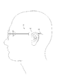
- FIG. 2 is a diagram showing the position and name of each part on the head of the human body.
- “Wa Ryo” is a part located at a place where the cheekbone in front of the bases of the left and right ears falls. Blood vessels called “superficial temporal artery” and “superficial temporal vein” pass under the skin of “Wayo”.
- “floating white” is a portion located on the hairline behind the ear, and in the shallow depth thereof, blood vessels called posterior auricular artery and posterior auricular vein are formed. Passing through. These blood vessels are blood vessels that have a particularly large blood flow rate among blood vessels that travel on the head of a human body, and that have a large increase / decrease width of the blood flow rate associated with the pulsation of the heart.
- the blood flow rate includes the amount of blood flowing per unit time or information indicating the amount.
- the measurement unit 110 can measure the biological information with high accuracy at “warming” or “floating” that is a position facing these blood vessels. Since a blood vessel with a large blood flow passes under the skin of “Wayo” and “Fukuhaku”, the measurement unit 110 is configured so that the physical unit difference of the user who uses the biological information measuring device 100 or the head Even if the mounting position of the measuring unit 110 is shifted, the biological information can be measured with high accuracy.
- “Wa Ryo” and “Fukihaku” are parts where hair does not grow easily. Therefore, the measurement part 110 becomes difficult to receive the influence of hair when measuring biological information, and can measure biological information accurately.
- the measurement unit 110 can be arranged in any device, apparatus, device, clothing, tool, armor, tool, or the like that can be attached to the human head.
- FIG. 3 is a graph showing the change over time of the measured value of the signal intensity measured by the measurement unit 110. From this measurement value, the measurement unit 110 calculates the blood flow of blood flowing through the blood vessel, the amount of oxygen contained in hemoglobin in red blood cells, the pulse wave, the pulse, the pulse wave propagation speed, the blood oxygen saturation, the blood oxygen concentration, etc. It is possible to measure the biological information. As shown in FIG. 3, the signal intensity measured by the measurement unit 110 periodically changes over time.
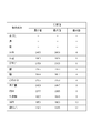
- FIG. 4 is a table showing measured values of signal intensity measured by the measurement unit 110 at each part shown in FIG. In FIG. 4, it shows that the signal strength measured by the measurement part 110 is so strong that the difference of the maximum value and minimum value of a measured value is large.
- FIG. 4 shows the maximum value and the minimum value in any one cycle of the periodic change of the signal intensity shown in FIG. 3, and the difference value thereof.
- the difference values in “Wa Ryo” and “Floating White” are particularly larger than the difference values in other parts. From this result, it is understood that the measurement unit 110 according to an embodiment of the present disclosure can accurately measure biological information in “warming” and “floating”.
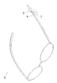
- FIG. 5 is a perspective view showing a schematic configuration of the eyeglass-type biological information measuring device 100.
- FIG. 5 shows an example in which the measurement unit 110 is arranged at a portion where the glasses are put on the ear when the wearing unit 130 is glasses.
- FIG. 6 is a perspective view showing a schematic configuration of the neckband-type biological information measuring device 100.
- FIG. 6 shows an example in which the measuring unit 110 is arranged in a portion where the neckband is covered with the ear when the wearing unit 130 is a neckband.
- FIG. 7 is a side view showing the head of a human body to which the glasses-type biological information measuring device 100 is attached.
- FIG. 7 illustrates an example in which the measurement unit 110 is disposed so as to be “warm” when the mounting unit 130 is glasses.
- FIG. 8 is a side view showing the head of a human body to which the neckband type biological information measuring device 100 is attached.
- FIG. 8 illustrates an example in which the measurement unit 110 is arranged to be “floating” when the mounting unit 130 is a neckband.
- FIG. 9 is an exploded view showing a schematic configuration of the measurement unit 110.
- FIG. 10 is a perspective view illustrating a schematic configuration of the measurement unit 110.
- FIG. 10 is a perspective view showing the assembled parts shown in FIG. 11 and 12 are cross-sectional views showing a schematic configuration in which the AA cross section shown in FIG. 10 is observed in the arrow direction.
- 13 is a cross-sectional view showing a schematic configuration of the BB cross section shown in FIG. 10 observed in the direction of the arrow.
- the measurement unit 110 includes a sensor unit 111, an inner case 112, a light emitting unit cover 113a, a light receiving unit cover 113b, an outer case 114, an elastic member 115a, and an elastic member 115b.
- the sensor unit 111 measures biological information by detecting the state of blood flowing through a blood vessel.
- the sensor unit 111 includes a first sensor unit 111a, a second sensor unit 111d, and a circuit board 111g.
- An example of the state of blood detected by the sensor unit 111 is the amount of oxyhemoglobin contained in the blood. Based on the detected amount of oxyhemoglobin, the sensor unit 111, for example, the blood flow of blood flowing through a blood vessel, the amount of oxygen contained in hemoglobin in red blood cells, pulse wave, pulse, pulse wave propagation speed, blood oxygen saturation Biological information such as blood oxygen concentration can be measured.
- the first sensor unit 111a includes a light emitting unit 111b and a light receiving unit 111c, and detects the state of blood flowing through a blood vessel.
- the light emitting unit 111b includes a light emitting element such as an LED (light emitting diode) or an LD (laser diode).
- the light receiving unit 111c includes a light receiving element such as PT (Phototransistor) or PD (Photodiode). The light receiving unit 111c receives reflected light of the light emitted from the light emitting unit 111b and outputs a signal corresponding to the intensity of the received light.
- the biological information that can be obtained by the light emitting unit 111b and the light receiving unit 111c includes a pulse wave.
- the sensor unit 111 When measuring the pulse wave, the sensor unit 111 emits light that is easily reflected by blood toward the human body from the light emitting unit 111b, and the light reflected from the human body is received by the light receiving unit 111c.
- the sensor unit 111 measures the pulse wave by analyzing the signal output from the light receiving unit 111c according to the intensity of the received light. In one embodiment of the present disclosure, the reflection includes scattering.
- the second sensor unit 111d includes an acceleration sensor 111e and a gyro sensor 111f, and detects the movement of the wearer.
- the acceleration sensor 111e detects the acceleration of the wearer.
- the gyro sensor 111f detects the wearer's angular velocity or angular acceleration.
- the second sensor unit 111d may be configured to include any sensor capable of detecting the movement of the wearer in addition to the acceleration sensor 111e and the gyro sensor 111f.
- the second sensor unit 111d may be configured to include only one of the acceleration sensor 111e and the gyro sensor 111f.
- the sensor unit 111 may not be able to measure biological information with high accuracy.
- the sensor unit 111 detects the movement of the wearer by the second sensor unit 111d, and corrects the influence on the biological information due to the movement of the wearer based on the detected movement. Therefore, the sensor unit 111 can accurately measure the biological information without being affected by the movement of the wearer.
- the second sensor unit 111d may be arranged at an arbitrary position where the movement of the wearer can be detected in addition to the sensor unit 111.
- the circuit board 111g is attached with components, devices, and devices that constitute the sensor unit 111, such as a processor, a storage device, a network interface, and an electronic component. And a wired substrate.
- the inner case 112 includes an inner case upper portion 112a and an inner case bottom portion 112b.
- the inner case 112 covers the sensor unit 111 to shield light from the outside or protect the inside of the inner case 112. Since the inner case 112 is intended to shield the sensor unit 111 from the outside, it may have a high light shielding property.
- the inner case 112 may be made of ABS (Acrylonitrile Butadiene Styrene) resin.
- the inner case upper part 112a includes openings in the light emitting direction by the light emitting part 111b and the light receiving direction by the light receiving part 111c.
- Both the light emitting unit cover 113a and the light receiving unit cover 113b transmit the wavelength emitted by the light emitting unit 111b.
- the light emitting unit cover 113a and the light receiving unit cover 113b are both attached to the opening of the inner case upper portion 112a to protect the inside of the inner case 112.
- the outer case 114 includes an outer case upper part 114a and an outer case bottom part 114b.
- the outer case 114 supports the inner case 112 inside the outer case 114 via the elastic member 115a and the elastic member 115b so that the inner case 112 can be displaced in all directions.
- the outer case upper part 114a includes an opening on the inner case upper part 112a side.
- the elastic member 115a and the elastic member 115b are arranged so as to generate an elastic force between the inner case bottom portion 112b and the outer case bottom portion 114b, so that the inner case 112 can be displaced in all directions inside the outer case 114.
- the elastic member 115a and the elastic member 115b are arbitrary members that generate elastic force, for example, springs, rubber, flexible resin, those using hydraulic pressure, those using air pressure, or those using water pressure. Etc.
- the inner case 112 protrudes to the outside from the outer case 114 as shown in FIG. 10 due to the elastic force of the elastic members 115a and 115b. That is, in the measurement unit 110, when the biological information measurement device 100 is attached to the head of a human body, the inner case 112 comes into contact with the head epidermis before the outer case 114.
- the measuring unit 110 emits light from the light emitting unit 111b toward the human body while the biological information measuring device 100 is attached to the head of the human body, and the light receiving unit 111c receives the reflected light from the human body. To be fixed to the mounting portion 130.
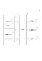
- At least one of the elastic member 115a or the elastic member 115b is compressed by the pressing force from the head skin as shown in the lower diagram of FIG. Retract.
- the inner case 112 moves from the state shown in the upper diagram of FIG. 12 to the state shown in the lower diagram of FIG. 12 or the upper diagram of FIG. It moves so that it may follow a head epidermis from the state shown to the state shown in the lower figure of FIG. Therefore, the inner case 112 is always in close contact with the head epidermis.
- the measuring unit 110 can be displaced in all directions with respect to the mounting unit 130 in a state where the fixing unit 120 is fixed to the mounting unit 130 by using the elastic member 115a and the elastic member 115b. Supported. Thereby, the measurement part 110 can keep the distance with the blood vessel constant. Therefore, the measurement unit 110 can accurately measure biological information.
- the measurement unit 110 uses the elastic member 115a and the elastic member 115b, so that the inner case 112 and the head epidermis are always in close contact with each other, thereby preventing external light from entering the inner case 112. it can. Therefore, the measurement unit 110 according to an embodiment of the present disclosure can measure biological information with high accuracy.
- the measurement unit 110 uses the elastic member 115a and the elastic member 115b to relieve the impact caused by the contact between the inner case 112 and the head epidermis and the pressure on the head epidermis by the inner case 112. . Therefore, the measurement part 110 which concerns on one Embodiment of this indication can improve the feeling of pressure given with respect to a head epidermis, and can improve a wear feeling.
- FIG. 14 is a block diagram showing a functional configuration of the biological information measuring apparatus 100.
- the biological information measuring apparatus 100 includes a control unit 101, a storage unit 102, a communication unit 103, a power supply unit 104, and a sensor unit 111.
- the control unit 101 controls and manages the entire sensor unit 111 such as controlling the light emission of the light emitting unit 111b and measuring biological information based on signals output from the light receiving unit 111c, the acceleration sensor 111e, and the gyro sensor 111f. Processor.
- the control unit 101 includes, for example, a processor such as a CPU (Central Processing Unit) that executes a program that defines a control procedure and a program that measures biological information.
- a processor such as a CPU (Central Processing Unit) that executes a program that defines a control procedure and a program that measures biological information.
- CPU Central Processing Unit
- the storage unit 102 includes a semiconductor memory, a magnetic memory, or the like, and stores various data and various programs and also functions as a work memory.
- Data stored in the storage unit 102 is, for example, data relating to measured biological information, parameters for operating the sensor unit 111, and the like.
- Examples of the program stored in the storage unit 102 include a program for operating the sensor unit 111, a program for measuring biological information based on signals output from the light receiving unit 111c, the acceleration sensor 111e, and the gyro sensor 111f. is there.
- the communication unit 103 transmits / receives various data to / from the external device by performing wired communication or wireless communication with the external device.
- the communication unit 103 communicates with, for example, a device (such as a mobile phone, a smartphone, a tablet, or a personal computer) operated by a wearer of the biological information measurement device 100 or a server device that exists on the network, and the sensor unit 111 performs measurement.
- the measurement result of the biological information is transmitted to the device.
- the power supply unit 104 includes a secondary battery such as a lithium ion battery and a control circuit for controlling charging and discharging thereof, and supplies power to the entire sensor unit 111.
- the power supply unit 104 may include a primary battery such as a button battery instead of the secondary battery.
- an embodiment of the present disclosure may be configured as a biological information measurement system 400 in which a biological information measurement device 100 and an external device 200 are connected via a network 300 as illustrated in FIG.
- the biological information measurement device 100 is configured as a detection device that notifies the external device 200 of the detection results of the first sensor unit 111a and the second sensor unit 111d, and measures biological information. It may be configured not to do so.
- the external device 200 may be configured to measure biological information based on the detection result notified from the biological information measurement device 100.
- the external device 200 is, for example, a mobile phone, a smartphone, a tablet, a personal computer, or a server device.
- the pulse wave has been described as the biological information that can be obtained by the light emitting unit 111b and the light receiving unit 111c.
- an embodiment of the present disclosure is not limited to this.
- blood oxygen saturation or blood oxygen concentration may be included as biological information that can be obtained by the light emitting unit 111b and the light receiving unit 111c.
- the sensor unit 111 In order to measure the blood oxygen saturation or blood oxygen concentration, the sensor unit 111 directs light having a wavelength different in absorbance according to the amount of oxygen contained in hemoglobin in red blood cells from the light emitting unit 111b. Light that is emitted and reflected from the human body is received by the light receiving unit 111c. The sensor unit 111 measures a blood oxygen saturation level or a blood oxygen concentration by analyzing a signal output from the light receiving unit 111c according to the intensity of the received light.
- the sensor unit 111 includes a function of measuring a pulse wave.
- the sensor unit 111 can acquire a pulse wave with high accuracy, the sensor unit 111 may include a function of measuring arbitrary biological information that can be measured based on the pulse wave.
- the sensor unit 111 may include a function of measuring blood pressure, pulse, and pulse wave propagation velocity from the acquired pulse wave.
- the biological information measuring device 100 includes a function of measuring biological information by the light emitting unit 111b and the light receiving unit 111c.
- the biological information measuring apparatus 100 may include a function of measuring biological information by an arbitrary method capable of measuring biological information, for example, sound waves, radio waves, and the like.
Landscapes
- Health & Medical Sciences (AREA)
- Life Sciences & Earth Sciences (AREA)
- Physics & Mathematics (AREA)
- Engineering & Computer Science (AREA)
- Molecular Biology (AREA)
- General Health & Medical Sciences (AREA)
- Biophysics (AREA)
- Pathology (AREA)
- Veterinary Medicine (AREA)
- Biomedical Technology (AREA)
- Heart & Thoracic Surgery (AREA)
- Medical Informatics (AREA)
- Public Health (AREA)
- Surgery (AREA)
- Animal Behavior & Ethology (AREA)
- Cardiology (AREA)
- Physiology (AREA)
- Hematology (AREA)
- Otolaryngology (AREA)
- Spectroscopy & Molecular Physics (AREA)
- Optics & Photonics (AREA)
- Oral & Maxillofacial Surgery (AREA)
- Dentistry (AREA)
- Vascular Medicine (AREA)
- Signal Processing (AREA)
- Measurement Of The Respiration, Hearing Ability, Form, And Blood Characteristics Of Living Organisms (AREA)
- Measuring Pulse, Heart Rate, Blood Pressure Or Blood Flow (AREA)
Abstract
Ce dispositif de mesure d'informations biométriques comprend une unité de capteur qui mesure des informations biométriques. L'unité de capteur est supportée sur une unité de montage qui doit être montée sur la tête d'un corps humain et dans un état dans lequel l'unité de montage est montée sur la tête du corps humain, l'unité de capteur est disposée dans une position opposée à au moins l'une d'une artère ou d'une veine passant à travers la tête.
Priority Applications (1)
| Application Number | Priority Date | Filing Date | Title |
|---|---|---|---|
| US16/325,501 US11246500B2 (en) | 2016-08-30 | 2017-08-02 | Biological information measurement device, biological information measurement system, and biological information measurement method |
Applications Claiming Priority (2)
| Application Number | Priority Date | Filing Date | Title |
|---|---|---|---|
| JP2016-168351 | 2016-08-30 | ||
| JP2016168351A JP6659498B2 (ja) | 2016-08-30 | 2016-08-30 | 生体情報測定装置、生体情報測定システム、生体情報の測定方法 |
Publications (1)
| Publication Number | Publication Date |
|---|---|
| WO2018043018A1 true WO2018043018A1 (fr) | 2018-03-08 |
Family
ID=61309430
Family Applications (1)
| Application Number | Title | Priority Date | Filing Date |
|---|---|---|---|
| PCT/JP2017/028131 Ceased WO2018043018A1 (fr) | 2016-08-30 | 2017-08-02 | Dispositif de mesure d'informations biométriques, système de mesure d'informations biométriques et programme de mesure d'informations biométriques |
Country Status (3)
| Country | Link |
|---|---|
| US (1) | US11246500B2 (fr) |
| JP (1) | JP6659498B2 (fr) |
| WO (1) | WO2018043018A1 (fr) |
Families Citing this family (9)
| Publication number | Priority date | Publication date | Assignee | Title |
|---|---|---|---|---|
| NL2017538B1 (en) * | 2016-09-27 | 2018-04-04 | Agis Automatisering B V | Wireless vital sign monitoring |
| JP6891074B2 (ja) * | 2017-08-25 | 2021-06-18 | 京セラ株式会社 | 測定装置及び測定方法 |
| FI128165B (en) * | 2018-05-18 | 2019-11-29 | Corle Oy | body Sensor |
| JP7222509B2 (ja) * | 2018-05-24 | 2023-02-15 | 株式会社oneA | 睡眠状態測定装置 |
| JP2020025627A (ja) * | 2018-08-09 | 2020-02-20 | ソニー株式会社 | 生体情報取得装置、頭部装着型情報提示装置、及び生体情報取得方法 |
| JP7283652B2 (ja) * | 2018-10-04 | 2023-05-30 | シーイヤー株式会社 | 聴覚サポートデバイス |
| JP7389463B2 (ja) * | 2019-11-25 | 2023-11-30 | 株式会社oneA | 生体情報測定装置 |
| JP7470960B2 (ja) * | 2019-11-25 | 2024-04-19 | 株式会社oneA | 生体情報測定装置 |
| US20250143589A1 (en) * | 2023-11-03 | 2025-05-08 | California Institute Of Technology | Compact laser-powered speckle visibility spectroscopy devices |
Citations (5)
| Publication number | Priority date | Publication date | Assignee | Title |
|---|---|---|---|---|
| JPH0232802U (fr) * | 1988-08-25 | 1990-03-01 | ||
| JP2001245860A (ja) * | 2000-03-02 | 2001-09-11 | Denso Corp | 脈波検出装置 |
| JP2003033328A (ja) * | 2001-07-19 | 2003-02-04 | Nippon Seimitsu Sokki Kk | ハートレートモニターおよびハートレート測定方法 |
| WO2009001449A1 (fr) * | 2007-06-27 | 2008-12-31 | Pioneer Corporation | Dispositif d'écoute |
| JP2015223437A (ja) * | 2014-05-29 | 2015-12-14 | 公立大学法人広島市立大学 | 耳介装着型装置 |
Family Cites Families (17)
| Publication number | Priority date | Publication date | Assignee | Title |
|---|---|---|---|---|
| CN1242693A (zh) * | 1997-08-26 | 2000-01-26 | 精工爱普生株式会社 | 脉波诊断装置、运动指标检测装置、运动强度检测装置、心输出量检测装置、每搏输出量检测装置、心功能诊断装置及其检测方法 |
| US20030163051A1 (en) * | 2002-02-25 | 2003-08-28 | Colin Corporation | Systems and methods for measuring pulse wave velocity and augmentation index |
| US8700111B2 (en) * | 2009-02-25 | 2014-04-15 | Valencell, Inc. | Light-guiding devices and monitoring devices incorporating same |
| US20120029367A1 (en) * | 2010-07-31 | 2012-02-02 | Hobeika Hind Louis | Heart rate waterproof measuring apparatus |
| CN103596492B (zh) * | 2011-02-09 | 2017-02-22 | 麻省理工学院 | 耳戴式生命体征监视器 |
| US20150250418A1 (en) * | 2014-03-10 | 2015-09-10 | Icon Health & Fitness, Inc. | Optical Pulse Rate Monitor |
| US20150342481A1 (en) * | 2014-05-30 | 2015-12-03 | Microsoft Corporation | Motion compensation for optical heart rate sensors |
| US10478127B2 (en) * | 2014-06-23 | 2019-11-19 | Sherlock Solutions, LLC | Apparatuses, methods, processes, and systems related to significant detrimental changes in health parameters and activating lifesaving measures |
| JP6254501B2 (ja) | 2014-09-08 | 2017-12-27 | 京セラ株式会社 | 生体情報測定装置 |
| TWI538660B (zh) * | 2014-09-26 | 2016-06-21 | 原相科技股份有限公司 | 心跳偵測模組及其偵測、去噪方法 |
| JPWO2016103877A1 (ja) * | 2014-12-26 | 2017-10-05 | ソニー株式会社 | 制御装置 |
| US20180014741A1 (en) * | 2015-01-26 | 2018-01-18 | Chang-An Chou | Wearable physiological monitoring device |
| JP6389904B2 (ja) | 2015-01-29 | 2018-09-12 | 京セラ株式会社 | 測定装置およびセンサシステム |
| US11033231B2 (en) * | 2015-03-03 | 2021-06-15 | Valencell, Inc. | Stabilized monitoring devices |
| US10709388B2 (en) * | 2015-05-08 | 2020-07-14 | Staton Techiya, Llc | Biometric, physiological or environmental monitoring using a closed chamber |
| US20180146866A1 (en) * | 2015-05-15 | 2018-05-31 | Veriskin, Inc. | Cutaneous blood flow monitoring device |
| KR20170028130A (ko) * | 2015-09-03 | 2017-03-13 | 박준호 | 웨어러블 디바이스 |
-
2016
- 2016-08-30 JP JP2016168351A patent/JP6659498B2/ja active Active
-
2017
- 2017-08-02 WO PCT/JP2017/028131 patent/WO2018043018A1/fr not_active Ceased
- 2017-08-02 US US16/325,501 patent/US11246500B2/en not_active Expired - Fee Related
Patent Citations (5)
| Publication number | Priority date | Publication date | Assignee | Title |
|---|---|---|---|---|
| JPH0232802U (fr) * | 1988-08-25 | 1990-03-01 | ||
| JP2001245860A (ja) * | 2000-03-02 | 2001-09-11 | Denso Corp | 脈波検出装置 |
| JP2003033328A (ja) * | 2001-07-19 | 2003-02-04 | Nippon Seimitsu Sokki Kk | ハートレートモニターおよびハートレート測定方法 |
| WO2009001449A1 (fr) * | 2007-06-27 | 2008-12-31 | Pioneer Corporation | Dispositif d'écoute |
| JP2015223437A (ja) * | 2014-05-29 | 2015-12-14 | 公立大学法人広島市立大学 | 耳介装着型装置 |
Also Published As
| Publication number | Publication date |
|---|---|
| JP6659498B2 (ja) | 2020-03-04 |
| US11246500B2 (en) | 2022-02-15 |
| US20190167123A1 (en) | 2019-06-06 |
| JP2018033604A (ja) | 2018-03-08 |
Similar Documents
| Publication | Publication Date | Title |
|---|---|---|
| JP6659498B2 (ja) | 生体情報測定装置、生体情報測定システム、生体情報の測定方法 | |
| US12076126B2 (en) | Physiological monitoring devices having sensing elements decoupled from body motion | |
| US12226199B2 (en) | Use of body-worn radar for biometric measurements, contextual awareness and identification | |
| US20220280048A1 (en) | Multi-Wavelength Pulse Oximetry | |
| EP3171767B1 (fr) | Procédés et appareil permettant d'améliorer la qualité des signaux dans des dispositifs portables de surveillance biométrique | |
| KR102309289B1 (ko) | 와치형 이동 단말기 | |
| US9717448B2 (en) | Continuous transdermal monitoring system and method | |
| EP2116183B1 (fr) | Dispositif de surveillance cardiovasculaire opto-électrique robuste localisé sur l'oreille | |
| US20210298657A1 (en) | Wireless Sound Converting System Having Bio-Signal Sensing Function | |
| TWI651891B (zh) | 功率調整模組及具有該功率調整模組的穿戴裝置 | |
| JP6519978B2 (ja) | 生体情報検出装置及び電子機器 | |
| US11744519B2 (en) | Biological information measurement device | |
| JP2021121355A (ja) | 測定装置及び測定方法 | |
| JP5930012B1 (ja) | センサーユニット、生体情報検出装置、電子機器 | |
| WO2019244611A1 (fr) | Dispositif de mesure, procédé de mesure et programme de mesure | |
| WO2016092750A1 (fr) | Unité de capteur, appareil de détection d'informations biologiques, dispositif électronique et procédé de détection d'informations biologiques | |
| JP2016163731A (ja) | 生体情報検出装置、電子機器及び生体情報検出方法 | |
| US20250366728A1 (en) | Optical determination of a biometric parameter | |
| JP2016112092A (ja) | 生体情報検出装置、電子機器及び生体情報検出方法 | |
| US20210304788A1 (en) | Wireless Sound Converting System having Bio-Signal Sensing Function | |
| HK40009544A (en) | Physiological monitoring devices having sensing elements decoupled from body motion | |
| KR20120136648A (ko) | 생체 신호를 이용한 장치 제어 시스템 및 방법 | |
| HK1237631B (en) | Methods and apparatus for improving signal quality in wearable biometric monitoring devices |
Legal Events
| Date | Code | Title | Description |
|---|---|---|---|
| 121 | Ep: the epo has been informed by wipo that ep was designated in this application |
Ref document number: 17846027 Country of ref document: EP Kind code of ref document: A1 |
|
| NENP | Non-entry into the national phase |
Ref country code: DE |
|
| 122 | Ep: pct application non-entry in european phase |
Ref document number: 17846027 Country of ref document: EP Kind code of ref document: A1 |