WO2018043018A1 - 生体情報測定装置、生体情報測定システム及び生体情報の測定方法 - Google Patents
生体情報測定装置、生体情報測定システム及び生体情報の測定方法 Download PDFInfo
- Publication number
- WO2018043018A1 WO2018043018A1 PCT/JP2017/028131 JP2017028131W WO2018043018A1 WO 2018043018 A1 WO2018043018 A1 WO 2018043018A1 JP 2017028131 W JP2017028131 W JP 2017028131W WO 2018043018 A1 WO2018043018 A1 WO 2018043018A1
- Authority
- WO
- WIPO (PCT)
- Prior art keywords
- biological information
- unit
- information measuring
- head
- measuring device
- Prior art date
- Legal status (The legal status is an assumption and is not a legal conclusion. Google has not performed a legal analysis and makes no representation as to the accuracy of the status listed.)
- Ceased
Links
Images





Classifications
-
- A—HUMAN NECESSITIES
- A61—MEDICAL OR VETERINARY SCIENCE; HYGIENE
- A61B—DIAGNOSIS; SURGERY; IDENTIFICATION
- A61B5/00—Measuring for diagnostic purposes; Identification of persons
- A61B5/02—Detecting, measuring or recording for evaluating the cardiovascular system, e.g. pulse, heart rate, blood pressure or blood flow
- A61B5/024—Measuring pulse rate or heart rate
- A61B5/0245—Measuring pulse rate or heart rate by using sensing means generating electric signals, i.e. ECG signals
-
- A—HUMAN NECESSITIES
- A61—MEDICAL OR VETERINARY SCIENCE; HYGIENE
- A61B—DIAGNOSIS; SURGERY; IDENTIFICATION
- A61B5/00—Measuring for diagnostic purposes; Identification of persons
- A61B5/02—Detecting, measuring or recording for evaluating the cardiovascular system, e.g. pulse, heart rate, blood pressure or blood flow
- A61B5/021—Measuring pressure in heart or blood vessels
- A61B5/02108—Measuring pressure in heart or blood vessels from analysis of pulse wave characteristics
- A61B5/02125—Measuring pressure in heart or blood vessels from analysis of pulse wave characteristics of pulse wave propagation time
-
- A—HUMAN NECESSITIES
- A61—MEDICAL OR VETERINARY SCIENCE; HYGIENE
- A61B—DIAGNOSIS; SURGERY; IDENTIFICATION
- A61B5/00—Measuring for diagnostic purposes; Identification of persons
- A61B5/02—Detecting, measuring or recording for evaluating the cardiovascular system, e.g. pulse, heart rate, blood pressure or blood flow
- A61B5/026—Measuring blood flow
-
- A—HUMAN NECESSITIES
- A61—MEDICAL OR VETERINARY SCIENCE; HYGIENE
- A61B—DIAGNOSIS; SURGERY; IDENTIFICATION
- A61B5/00—Measuring for diagnostic purposes; Identification of persons
- A61B5/02—Detecting, measuring or recording for evaluating the cardiovascular system, e.g. pulse, heart rate, blood pressure or blood flow
- A61B5/026—Measuring blood flow
- A61B5/0261—Measuring blood flow using optical means, e.g. infrared light
-
- A—HUMAN NECESSITIES
- A61—MEDICAL OR VETERINARY SCIENCE; HYGIENE
- A61B—DIAGNOSIS; SURGERY; IDENTIFICATION
- A61B5/00—Measuring for diagnostic purposes; Identification of persons
- A61B5/103—Measuring devices for testing the shape, pattern, colour, size or movement of the body or parts thereof, for diagnostic purposes
- A61B5/11—Measuring movement of the entire body or parts thereof, e.g. head or hand tremor or mobility of a limb
-
- A—HUMAN NECESSITIES
- A61—MEDICAL OR VETERINARY SCIENCE; HYGIENE
- A61B—DIAGNOSIS; SURGERY; IDENTIFICATION
- A61B5/00—Measuring for diagnostic purposes; Identification of persons
- A61B5/145—Measuring characteristics of blood in vivo, e.g. gas concentration or pH-value ; Measuring characteristics of body fluids or tissues, e.g. interstitial fluid or cerebral tissue
- A61B5/1455—Measuring characteristics of blood in vivo, e.g. gas concentration or pH-value ; Measuring characteristics of body fluids or tissues, e.g. interstitial fluid or cerebral tissue using optical sensors, e.g. spectral photometrical oximeters
-
- A—HUMAN NECESSITIES
- A61—MEDICAL OR VETERINARY SCIENCE; HYGIENE
- A61B—DIAGNOSIS; SURGERY; IDENTIFICATION
- A61B5/00—Measuring for diagnostic purposes; Identification of persons
- A61B5/68—Arrangements of detecting, measuring or recording means, e.g. sensors, in relation to patient
- A61B5/6801—Arrangements of detecting, measuring or recording means, e.g. sensors, in relation to patient specially adapted to be attached to or worn on the body surface
- A61B5/6802—Sensor mounted on worn items
- A61B5/6803—Head-worn items, e.g. helmets, masks, headphones or goggles
-
- A—HUMAN NECESSITIES
- A61—MEDICAL OR VETERINARY SCIENCE; HYGIENE
- A61B—DIAGNOSIS; SURGERY; IDENTIFICATION
- A61B5/00—Measuring for diagnostic purposes; Identification of persons
- A61B5/68—Arrangements of detecting, measuring or recording means, e.g. sensors, in relation to patient
- A61B5/6801—Arrangements of detecting, measuring or recording means, e.g. sensors, in relation to patient specially adapted to be attached to or worn on the body surface
- A61B5/6813—Specially adapted to be attached to a specific body part
- A61B5/6814—Head
- A61B5/6815—Ear
- A61B5/6816—Ear lobe
-
- A—HUMAN NECESSITIES
- A61—MEDICAL OR VETERINARY SCIENCE; HYGIENE
- A61B—DIAGNOSIS; SURGERY; IDENTIFICATION
- A61B2560/00—Constructional details of operational features of apparatus; Accessories for medical measuring apparatus
- A61B2560/04—Constructional details of apparatus
- A61B2560/0443—Modular apparatus
-
- A—HUMAN NECESSITIES
- A61—MEDICAL OR VETERINARY SCIENCE; HYGIENE
- A61B—DIAGNOSIS; SURGERY; IDENTIFICATION
- A61B5/00—Measuring for diagnostic purposes; Identification of persons
- A61B5/02—Detecting, measuring or recording for evaluating the cardiovascular system, e.g. pulse, heart rate, blood pressure or blood flow
- A61B5/024—Measuring pulse rate or heart rate
- A61B5/02438—Measuring pulse rate or heart rate with portable devices, e.g. worn by the patient
Definitions
- the present disclosure relates to a biological information measuring device, a biological information measuring system, and a biological information measuring method.
- Patent Document 1 describes a biological information measuring device that measures pulse wave data by irradiating a test site from a light emitting element with measurement light and receiving reflected light from the test site with a light receiving element. Yes.
- the biological information measuring device includes a sensor unit that measures biological information.
- the sensor unit is supported by a mounting unit mounted on the head of a human body, and opposes at least one of an artery or a vein passing through the head with the mounting unit mounted on the head. Placed in position.
- a biological information measurement system includes a sensor unit that detects a state of blood flowing through a blood vessel, and a communication unit that notifies an external device of the detected state.
- the sensor unit includes a biological information measuring device and the external device.
- the biological information measuring device is supported by a mounting unit mounted on the head of a human body, and is attached to at least one of an artery or a vein passing through the head with the mounting unit mounted on the head. It arrange
- the external device measures biological information based on the state notified from the sensor unit.
- the biological information measuring method by the biological information measuring apparatus measures the biological information at a position facing at least one of an artery or a vein passing through the head of a human body.
- FIG. 11 is a cross-sectional view of the AA cross section shown in FIG. 10 observed in the arrow direction.
- FIG. 11 is a cross-sectional view of the AA cross section shown in FIG. 10 observed in the arrow direction.
- FIG. 11 is a cross-sectional view of the BB cross section shown in FIG. 10 observed in the direction of the arrow.
- the biological information measuring device, the biological information measuring system, and the biological information measuring method according to the present disclosure described below improve the measurement accuracy of biological information.
- FIG. 1 is a perspective view illustrating a schematic configuration of a biological information measuring apparatus 100 according to an embodiment of the present disclosure.
- the biological information measurement device 100 includes a measurement unit 110, a fixing unit 120, and a mounting unit 130.
- the measurement unit 110 measures biological information in a state where the biological information measuring device 100 is worn on the head of a human body.
- the position where the measurement unit 110 measures the biological information includes a position facing any artery or vein passing through the head of the human body.
- the biological information measured by the measurement unit 110 includes arbitrary biological information that can be measured by detecting the state of blood flowing through a blood vessel.
- the biological information measured by the measurement unit 110 includes, for example, the blood flow of blood flowing through blood vessels, the amount of oxygen contained in hemoglobin in red blood cells, the pulse wave, the pulse, the pulse wave propagation speed, the blood oxygen saturation, and the blood oxygen concentration. Etc.
- the blood vessel has an artery that sends blood from the heart, a vein that sends blood that returns to the heart, and a capillary that connects the ends (arterioles and venules).
- the measurement target of biological information is at least one of an artery and a vein. Arteries and veins have more blood flow than capillaries. Therefore, the measurement unit 110 according to an embodiment of the present disclosure accurately measures biological information at a position facing at least one of an artery or a vein as compared to the case where biological information is measured in a capillary vessel. be able to.
- the fixing unit 120 supports the measuring unit 110 and is fixed to the mounting unit 130. As shown in FIG. 1, the fixing portion 120 includes a through hole 121, a fixing tool 122, and a charging terminal 123.
- the through hole 121 includes a hole for allowing the mounting portion 130 to pass through the fixing portion 120.
- the fixing tool 122 includes a part for fixing the fixing unit 120 to the mounting unit 130 in a state where the mounting unit 130 is passed through the through hole 121.
- the fixing tool 122 is an arbitrary tool that fixes the fixing portion 120 to the mounting portion 130 in a state where the mounting portion 130 is passed through the through hole 121 and includes, for example, a fixing component such as a bolt or a screw.
- the fixing part 120 is detachably fixed to the mounting part 130 by the fixing tool 122. Therefore, the measurement unit 110 can be disposed at any position of the mounting unit 130 via the fixing unit 120, and can also be disposed in another mounting unit different from the mounting unit 130 illustrated in FIG.
- the charging terminal 123 includes a terminal for charging the secondary battery.
- the secondary battery supplies power for operating the measurement unit 110.
- the mounting part 130 is mounted on the human head.
- the mounting unit 130 includes any device, device, equipment, clothing, tool, armor, tool, or the like that is mounted on the human head.
- the wearing unit 130 includes a wearable device, a neckband, glasses, headphones, earphones, goggles, a head microphone, an earphone microphone, a headset, a head mounted display, a hearing aid, a hat, a helmet, or a mask.
- the position where the measurement unit 110 measures biological information is the head.
- the position where the measurement unit 110 can measure biological information may be other than the head.
- the head often has large blood vessels near the surface due to the presence of the skull. Therefore, fresh blood carried to the brain and blood rich in oxyhemoglobin flow into the head. Therefore, the measurement unit 110 according to an embodiment of the present disclosure can accurately measure biological information on the head.
- the measurement unit 110 will be described below assuming that measurement is performed in “warming” or “floating” as an example of a measurement part of biological information.
- FIG. 2 is a diagram showing the position and name of each part on the head of the human body.
- “Wa Ryo” is a part located at a place where the cheekbone in front of the bases of the left and right ears falls. Blood vessels called “superficial temporal artery” and “superficial temporal vein” pass under the skin of “Wayo”.
- “floating white” is a portion located on the hairline behind the ear, and in the shallow depth thereof, blood vessels called posterior auricular artery and posterior auricular vein are formed. Passing through. These blood vessels are blood vessels that have a particularly large blood flow rate among blood vessels that travel on the head of a human body, and that have a large increase / decrease width of the blood flow rate associated with the pulsation of the heart.
- the blood flow rate includes the amount of blood flowing per unit time or information indicating the amount.
- the measurement unit 110 can measure the biological information with high accuracy at “warming” or “floating” that is a position facing these blood vessels. Since a blood vessel with a large blood flow passes under the skin of “Wayo” and “Fukuhaku”, the measurement unit 110 is configured so that the physical unit difference of the user who uses the biological information measuring device 100 or the head Even if the mounting position of the measuring unit 110 is shifted, the biological information can be measured with high accuracy.
- “Wa Ryo” and “Fukihaku” are parts where hair does not grow easily. Therefore, the measurement part 110 becomes difficult to receive the influence of hair when measuring biological information, and can measure biological information accurately.
- the measurement unit 110 can be arranged in any device, apparatus, device, clothing, tool, armor, tool, or the like that can be attached to the human head.
- FIG. 3 is a graph showing the change over time of the measured value of the signal intensity measured by the measurement unit 110. From this measurement value, the measurement unit 110 calculates the blood flow of blood flowing through the blood vessel, the amount of oxygen contained in hemoglobin in red blood cells, the pulse wave, the pulse, the pulse wave propagation speed, the blood oxygen saturation, the blood oxygen concentration, etc. It is possible to measure the biological information. As shown in FIG. 3, the signal intensity measured by the measurement unit 110 periodically changes over time.
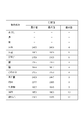
- FIG. 4 is a table showing measured values of signal intensity measured by the measurement unit 110 at each part shown in FIG. In FIG. 4, it shows that the signal strength measured by the measurement part 110 is so strong that the difference of the maximum value and minimum value of a measured value is large.
- FIG. 4 shows the maximum value and the minimum value in any one cycle of the periodic change of the signal intensity shown in FIG. 3, and the difference value thereof.
- the difference values in “Wa Ryo” and “Floating White” are particularly larger than the difference values in other parts. From this result, it is understood that the measurement unit 110 according to an embodiment of the present disclosure can accurately measure biological information in “warming” and “floating”.
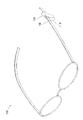
- FIG. 5 is a perspective view showing a schematic configuration of the eyeglass-type biological information measuring device 100.
- FIG. 5 shows an example in which the measurement unit 110 is arranged at a portion where the glasses are put on the ear when the wearing unit 130 is glasses.
- FIG. 6 is a perspective view showing a schematic configuration of the neckband-type biological information measuring device 100.
- FIG. 6 shows an example in which the measuring unit 110 is arranged in a portion where the neckband is covered with the ear when the wearing unit 130 is a neckband.
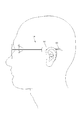
- FIG. 7 is a side view showing the head of a human body to which the glasses-type biological information measuring device 100 is attached.
- FIG. 7 illustrates an example in which the measurement unit 110 is disposed so as to be “warm” when the mounting unit 130 is glasses.
- FIG. 8 is a side view showing the head of a human body to which the neckband type biological information measuring device 100 is attached.
- FIG. 8 illustrates an example in which the measurement unit 110 is arranged to be “floating” when the mounting unit 130 is a neckband.
- FIG. 9 is an exploded view showing a schematic configuration of the measurement unit 110.
- FIG. 10 is a perspective view illustrating a schematic configuration of the measurement unit 110.
- FIG. 10 is a perspective view showing the assembled parts shown in FIG. 11 and 12 are cross-sectional views showing a schematic configuration in which the AA cross section shown in FIG. 10 is observed in the arrow direction.
- 13 is a cross-sectional view showing a schematic configuration of the BB cross section shown in FIG. 10 observed in the direction of the arrow.
- the measurement unit 110 includes a sensor unit 111, an inner case 112, a light emitting unit cover 113a, a light receiving unit cover 113b, an outer case 114, an elastic member 115a, and an elastic member 115b.
- the sensor unit 111 measures biological information by detecting the state of blood flowing through a blood vessel.
- the sensor unit 111 includes a first sensor unit 111a, a second sensor unit 111d, and a circuit board 111g.
- An example of the state of blood detected by the sensor unit 111 is the amount of oxyhemoglobin contained in the blood. Based on the detected amount of oxyhemoglobin, the sensor unit 111, for example, the blood flow of blood flowing through a blood vessel, the amount of oxygen contained in hemoglobin in red blood cells, pulse wave, pulse, pulse wave propagation speed, blood oxygen saturation Biological information such as blood oxygen concentration can be measured.
- the first sensor unit 111a includes a light emitting unit 111b and a light receiving unit 111c, and detects the state of blood flowing through a blood vessel.
- the light emitting unit 111b includes a light emitting element such as an LED (light emitting diode) or an LD (laser diode).
- the light receiving unit 111c includes a light receiving element such as PT (Phototransistor) or PD (Photodiode). The light receiving unit 111c receives reflected light of the light emitted from the light emitting unit 111b and outputs a signal corresponding to the intensity of the received light.
- the biological information that can be obtained by the light emitting unit 111b and the light receiving unit 111c includes a pulse wave.
- the sensor unit 111 When measuring the pulse wave, the sensor unit 111 emits light that is easily reflected by blood toward the human body from the light emitting unit 111b, and the light reflected from the human body is received by the light receiving unit 111c.
- the sensor unit 111 measures the pulse wave by analyzing the signal output from the light receiving unit 111c according to the intensity of the received light. In one embodiment of the present disclosure, the reflection includes scattering.
- the second sensor unit 111d includes an acceleration sensor 111e and a gyro sensor 111f, and detects the movement of the wearer.
- the acceleration sensor 111e detects the acceleration of the wearer.
- the gyro sensor 111f detects the wearer's angular velocity or angular acceleration.
- the second sensor unit 111d may be configured to include any sensor capable of detecting the movement of the wearer in addition to the acceleration sensor 111e and the gyro sensor 111f.
- the second sensor unit 111d may be configured to include only one of the acceleration sensor 111e and the gyro sensor 111f.
- the sensor unit 111 may not be able to measure biological information with high accuracy.
- the sensor unit 111 detects the movement of the wearer by the second sensor unit 111d, and corrects the influence on the biological information due to the movement of the wearer based on the detected movement. Therefore, the sensor unit 111 can accurately measure the biological information without being affected by the movement of the wearer.
- the second sensor unit 111d may be arranged at an arbitrary position where the movement of the wearer can be detected in addition to the sensor unit 111.
- the circuit board 111g is attached with components, devices, and devices that constitute the sensor unit 111, such as a processor, a storage device, a network interface, and an electronic component. And a wired substrate.
- the inner case 112 includes an inner case upper portion 112a and an inner case bottom portion 112b.
- the inner case 112 covers the sensor unit 111 to shield light from the outside or protect the inside of the inner case 112. Since the inner case 112 is intended to shield the sensor unit 111 from the outside, it may have a high light shielding property.
- the inner case 112 may be made of ABS (Acrylonitrile Butadiene Styrene) resin.
- the inner case upper part 112a includes openings in the light emitting direction by the light emitting part 111b and the light receiving direction by the light receiving part 111c.
- Both the light emitting unit cover 113a and the light receiving unit cover 113b transmit the wavelength emitted by the light emitting unit 111b.
- the light emitting unit cover 113a and the light receiving unit cover 113b are both attached to the opening of the inner case upper portion 112a to protect the inside of the inner case 112.
- the outer case 114 includes an outer case upper part 114a and an outer case bottom part 114b.
- the outer case 114 supports the inner case 112 inside the outer case 114 via the elastic member 115a and the elastic member 115b so that the inner case 112 can be displaced in all directions.
- the outer case upper part 114a includes an opening on the inner case upper part 112a side.
- the elastic member 115a and the elastic member 115b are arranged so as to generate an elastic force between the inner case bottom portion 112b and the outer case bottom portion 114b, so that the inner case 112 can be displaced in all directions inside the outer case 114.
- the elastic member 115a and the elastic member 115b are arbitrary members that generate elastic force, for example, springs, rubber, flexible resin, those using hydraulic pressure, those using air pressure, or those using water pressure. Etc.
- the inner case 112 protrudes to the outside from the outer case 114 as shown in FIG. 10 due to the elastic force of the elastic members 115a and 115b. That is, in the measurement unit 110, when the biological information measurement device 100 is attached to the head of a human body, the inner case 112 comes into contact with the head epidermis before the outer case 114.
- the measuring unit 110 emits light from the light emitting unit 111b toward the human body while the biological information measuring device 100 is attached to the head of the human body, and the light receiving unit 111c receives the reflected light from the human body. To be fixed to the mounting portion 130.
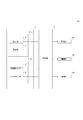
- At least one of the elastic member 115a or the elastic member 115b is compressed by the pressing force from the head skin as shown in the lower diagram of FIG. Retract.
- the inner case 112 moves from the state shown in the upper diagram of FIG. 12 to the state shown in the lower diagram of FIG. 12 or the upper diagram of FIG. It moves so that it may follow a head epidermis from the state shown to the state shown in the lower figure of FIG. Therefore, the inner case 112 is always in close contact with the head epidermis.
- the measuring unit 110 can be displaced in all directions with respect to the mounting unit 130 in a state where the fixing unit 120 is fixed to the mounting unit 130 by using the elastic member 115a and the elastic member 115b. Supported. Thereby, the measurement part 110 can keep the distance with the blood vessel constant. Therefore, the measurement unit 110 can accurately measure biological information.
- the measurement unit 110 uses the elastic member 115a and the elastic member 115b, so that the inner case 112 and the head epidermis are always in close contact with each other, thereby preventing external light from entering the inner case 112. it can. Therefore, the measurement unit 110 according to an embodiment of the present disclosure can measure biological information with high accuracy.
- the measurement unit 110 uses the elastic member 115a and the elastic member 115b to relieve the impact caused by the contact between the inner case 112 and the head epidermis and the pressure on the head epidermis by the inner case 112. . Therefore, the measurement part 110 which concerns on one Embodiment of this indication can improve the feeling of pressure given with respect to a head epidermis, and can improve a wear feeling.
- FIG. 14 is a block diagram showing a functional configuration of the biological information measuring apparatus 100.
- the biological information measuring apparatus 100 includes a control unit 101, a storage unit 102, a communication unit 103, a power supply unit 104, and a sensor unit 111.
- the control unit 101 controls and manages the entire sensor unit 111 such as controlling the light emission of the light emitting unit 111b and measuring biological information based on signals output from the light receiving unit 111c, the acceleration sensor 111e, and the gyro sensor 111f. Processor.
- the control unit 101 includes, for example, a processor such as a CPU (Central Processing Unit) that executes a program that defines a control procedure and a program that measures biological information.
- a processor such as a CPU (Central Processing Unit) that executes a program that defines a control procedure and a program that measures biological information.
- CPU Central Processing Unit
- the storage unit 102 includes a semiconductor memory, a magnetic memory, or the like, and stores various data and various programs and also functions as a work memory.
- Data stored in the storage unit 102 is, for example, data relating to measured biological information, parameters for operating the sensor unit 111, and the like.
- Examples of the program stored in the storage unit 102 include a program for operating the sensor unit 111, a program for measuring biological information based on signals output from the light receiving unit 111c, the acceleration sensor 111e, and the gyro sensor 111f. is there.
- the communication unit 103 transmits / receives various data to / from the external device by performing wired communication or wireless communication with the external device.
- the communication unit 103 communicates with, for example, a device (such as a mobile phone, a smartphone, a tablet, or a personal computer) operated by a wearer of the biological information measurement device 100 or a server device that exists on the network, and the sensor unit 111 performs measurement.
- the measurement result of the biological information is transmitted to the device.
- the power supply unit 104 includes a secondary battery such as a lithium ion battery and a control circuit for controlling charging and discharging thereof, and supplies power to the entire sensor unit 111.
- the power supply unit 104 may include a primary battery such as a button battery instead of the secondary battery.
- an embodiment of the present disclosure may be configured as a biological information measurement system 400 in which a biological information measurement device 100 and an external device 200 are connected via a network 300 as illustrated in FIG.
- the biological information measurement device 100 is configured as a detection device that notifies the external device 200 of the detection results of the first sensor unit 111a and the second sensor unit 111d, and measures biological information. It may be configured not to do so.
- the external device 200 may be configured to measure biological information based on the detection result notified from the biological information measurement device 100.
- the external device 200 is, for example, a mobile phone, a smartphone, a tablet, a personal computer, or a server device.
- the pulse wave has been described as the biological information that can be obtained by the light emitting unit 111b and the light receiving unit 111c.
- an embodiment of the present disclosure is not limited to this.
- blood oxygen saturation or blood oxygen concentration may be included as biological information that can be obtained by the light emitting unit 111b and the light receiving unit 111c.
- the sensor unit 111 In order to measure the blood oxygen saturation or blood oxygen concentration, the sensor unit 111 directs light having a wavelength different in absorbance according to the amount of oxygen contained in hemoglobin in red blood cells from the light emitting unit 111b. Light that is emitted and reflected from the human body is received by the light receiving unit 111c. The sensor unit 111 measures a blood oxygen saturation level or a blood oxygen concentration by analyzing a signal output from the light receiving unit 111c according to the intensity of the received light.
- the sensor unit 111 includes a function of measuring a pulse wave.
- the sensor unit 111 can acquire a pulse wave with high accuracy, the sensor unit 111 may include a function of measuring arbitrary biological information that can be measured based on the pulse wave.
- the sensor unit 111 may include a function of measuring blood pressure, pulse, and pulse wave propagation velocity from the acquired pulse wave.
- the biological information measuring device 100 includes a function of measuring biological information by the light emitting unit 111b and the light receiving unit 111c.
- the biological information measuring apparatus 100 may include a function of measuring biological information by an arbitrary method capable of measuring biological information, for example, sound waves, radio waves, and the like.
Landscapes
- Health & Medical Sciences (AREA)
- Life Sciences & Earth Sciences (AREA)
- Physics & Mathematics (AREA)
- Engineering & Computer Science (AREA)
- General Health & Medical Sciences (AREA)
- Pathology (AREA)
- Biomedical Technology (AREA)
- Heart & Thoracic Surgery (AREA)
- Medical Informatics (AREA)
- Molecular Biology (AREA)
- Surgery (AREA)
- Animal Behavior & Ethology (AREA)
- Biophysics (AREA)
- Public Health (AREA)
- Veterinary Medicine (AREA)
- Cardiology (AREA)
- Physiology (AREA)
- Hematology (AREA)
- Otolaryngology (AREA)
- Spectroscopy & Molecular Physics (AREA)
- Optics & Photonics (AREA)
- Vascular Medicine (AREA)
- Dentistry (AREA)
- Oral & Maxillofacial Surgery (AREA)
- Signal Processing (AREA)
- Measuring Pulse, Heart Rate, Blood Pressure Or Blood Flow (AREA)
- Measurement Of The Respiration, Hearing Ability, Form, And Blood Characteristics Of Living Organisms (AREA)
Abstract
生体情報測定装置は、生体情報を測定するセンサ部を含み、センサ部は、人体の頭部に装着される装着部に支持され、装着部が頭部に装着された状態で、頭部を通る動脈、又は、静脈の少なくともいずれかに対向する位置に配置される。
Description
本出願は、日本国特許出願2016-168351号(2016年8月30日出願)の優先権を主張するものであり、当該出願の開示全体を、ここに参照のために取り込む。
本開示は、生体情報測定装置、生体情報測定システム、生体情報の測定方法に関する。
従来、脈波などのユーザの生体情報を測定する生体情報測定装置が知られている。生体情報の測定は、生体情報測定装置を使用して種々の方法により行われる。例えば、特許文献1には、発光素子から被検部位に測定光を照射し、受光素子で被検部位からの反射光を受光することにより脈波データを測定する生体情報測定装置が記載されている。
一実施形態に係る生体情報測定装置は、生体情報を測定するセンサ部を含む。前記センサ部は、人体の頭部に装着される装着部に支持され、前記装着部が前記頭部に装着された状態で、前記頭部を通る動脈、又は、静脈の少なくともいずれかに対向する位置に配置される。
一実施形態に係る生体情報測定システムは、血管を流れる血液の状態を検知するセンサ部と、検知された前記状態を外部装置に通知する通信部と、を含む。前記センサ部は、生体情報測定装置と、前記外部装置とを含む。前記生体情報測定装置は、人体の頭部に装着される装着部に支持され、前記装着部が前記頭部に装着された状態で、前記頭部を通る動脈、又は、静脈の少なくともいずれかに対向する位置に配置される。前記外部装置は、前記センサ部から通知された前記状態に基づいて生体情報を測定する。
一実施形態に係る生体情報測定装置による生体情報の測定方法は、人体の頭部を通る動脈、又は、静脈の少なくともいずれかに対向する位置において前記生体情報を測定する。
生体情報測定装置は、取得される信号強度が弱いと、精度良く生体情報を測定することが困難な場合がある。以下で説明する、本開示に係る生体情報測定装置、生体情報測定システム及び生体情報の測定方法は、生体情報の測定精度を向上させる。
以下、本開示の実施形態について、図面を参照して詳細に説明する。
本開示の一実施形態に係る生体情報測定装置100の概略構成について、図1を参照して説明する。図1は、本開示の一実施形態に係る生体情報測定装置100の概略構成を示す斜視図である。
図1に示すように、本開示の一実施形態に係る生体情報測定装置100は、測定部110と、固定部120と、装着部130とを含む。
測定部110は、生体情報測定装置100が人体の頭部に装着されている状態で生体情報を測定する。測定部110が生体情報を測定する位置は、人体の頭部を通る任意の動脈、又は、静脈の少なくともいずれかに対向する位置を含む。測定部110が測定する生体情報は、血管を流れる血液の状態を検知することで測定可能な任意の生体情報を含む。測定部110が測定する生体情報は、例えば、血管を流れる血液の血流量、赤血球中のヘモグロビンに含まれる酸素量、脈波、脈拍、脈波伝搬速度、血中酸素飽和度、血中酸素濃度などを含む。
血管は、心臓から出る血液を送る動脈と、心臓へ戻る血液を送る静脈と、それらの末端(細動脈と細静脈)をつなぐ毛細血管とを有する。本開示の一実施形態においては、生体情報の測定対象は、動脈、又は、静脈の少なくともいずれかである。動脈、及び、静脈は、毛細血管に比べて血流量が多い。そのため、本開示の一実施形態に係る測定部110は、毛細血管において生体情報を測定する場合と比較して、動脈、又は、静脈の少なくともいずれかに対向する位置において生体情報を精度良く測定することができる。
固定部120は、測定部110を支持し、装着部130に固定される。図1に示すように、固定部120は、通し穴121と、固定用具122と、充電端子123とを含む。
通し穴121は、装着部130を固定部120に通すための穴を含む。固定用具122は、装着部130が通し穴121に通された状態で固定部120を装着部130に固定するための部品を含む。固定用具122は、装着部130が通し穴121に通された状態で固定部120を装着部130に固定する任意の用具であり、例えば、ボルト、又は、ネジなどの固定用の部品を含む。
このように、固定部120は、固定用具122により、装着部130に対して着脱可能に固定される。そのため、測定部110は、固定部120を介して、装着部130の任意の位置に配置可能であり、また、図1に示す装着部130とは異なる他の装着部にも配置可能である。
充電端子123は、二次電池を充電するための端子を含む。二次電池は、測定部110を動作させるための電力を供給する。
装着部130は、人体の頭部に装着される。装着部130は、人体の頭部に装着される任意の器具、装置、機器、衣類、道具、防具、用具などを含む。例えば、装着部130は、ウェアラブルデバイス、ネックバンド、メガネ、ヘッドホン、イヤホン、ゴーグル、ヘッドマイク、イヤホンマイク、ヘッドセット、ヘッドマウントディスプレイ、補聴器、帽子、ヘルメット、又はマスクなどを含む。
本開示の一実施形態においては、測定部110が生体情報を測定する位置が頭部であるとする。ただし、測定部110が生体情報を測定することが可能な位置は頭部以外であってもよい。頭部は、頭蓋骨が存在することから表層近くに大きな血管が通っていることが多い。そのため、脳に運ばれる新鮮な血液、及び、オキシヘモグロビンを多く含んだ血液が、頭部に流れ込む。そのため、本開示の一実施形態に係る測定部110は、頭部において生体情報を精度良く測定することができる。本開示の一実施形態において、測定部110は、生体情報の測定部位の一例として、「和りょう」、又は、「浮白」において測定を行うとして、以下、説明を行う。
図2は、人体の頭部における各部位の位置と名称を示す図である。図2に示すように、「和りょう」は、左右の耳のつけ根の前にある頬骨が落ち込む箇所に位置する部位である。「和りょう」の皮下浅くには、浅側頭動脈、及び、浅側頭静脈と呼ばれる血管が通っている。
図2に示すように、「浮白」は、耳の後ろの髪の生え際の上に位置する部位であり、その皮下浅くには、後耳介動脈、及び、後耳介静脈と呼ばれる血管が通っている。これらの血管は、人体の頭部を走行する血管のなかでも特に血流量が多く、また、心臓の拍動に伴う血流量の増減幅が大きい血管である。血流量とは、単位時間当たりに流れる血液の量、若しくは、その量を表す情報を含む。
そのため、測定部110は、これらの血管に対向する位置である「和りょう」、又は、「浮白」において、生体情報を精度良く測定することができる。「和りょう」、及び、「浮白」の皮下浅くには血流量が多い血管が通っているため、測定部110は、生体情報測定装置100を使用するユーザの体格差、又は、頭部における測定部110の装着位置のずれがあっても、生体情報を精度良く測定することができる。
「和りょう」、及び、「浮白」は、頭髪が生えにくい部位である。そのため、測定部110は、生体情報を測定する際に頭髪の影響を受けにくくなり、生体情報を精度良く測定することができる。
図2に示すように、「和りょう」、及び、「浮白」は、耳の近くに位置する。このことから、本開示の一実施形態に係る測定部110は、人体の頭部に装着可能なあらゆる器具、装置、機器、衣類、道具、防具、又は用具などに配置可能である。
図3は、測定部110により測定される信号強度の測定値の経時変化を示すグラフである。測定部110は、この測定値から、血管を流れる血液の血流量、赤血球中のヘモグロビンに含まれる酸素量、脈波、脈拍、脈波伝搬速度、血中酸素飽和度、又は血中酸素濃度などの生体情報を測定することができる。図3に示すように、測定部110により測定される信号強度は、時間経過と共に周期的に変化する。
図4は、図2に示す各部位において測定部110により測定される信号強度の測定値を示す表である。図4においては、測定値の最大値と最小値との差分が大きいほど、測定部110により測定される信号強度が強いことを示す。図4には、図3に示した信号強度の周期的な変化の任意の1周期における最大値と最小値、及び、それらの差分値を示している。
図4に示すように、「和りょう」、及び、「浮白」における差分値は、他の部位における差分値よりも特に大きい。この結果から、本開示の一実施形態に係る測定部110は、「和りょう」、及び、「浮白」において、生体情報を精度良く測定することができることが理解される。
図5は、メガネ型の生体情報測定装置100の概略構成を示す斜視図である。図5は、装着部130がメガネである場合に、メガネが耳にかかる部分に測定部110が配置されている例を示している。
図6は、ネックバンド型の生体情報測定装置100の概略構成を示す斜視図である。図6は、装着部130がネックバンドである場合に、ネックバンドが耳にかかる部分に測定部110が配置されている例を示している。
図7は、メガネ型の生体情報測定装置100が装着された人体の頭部を示す側面図である。図7は、装着部130がメガネである場合に、測定部110が「和りょう」に位置するように配置されている例を示している。
図8は、ネックバンド型の生体情報測定装置100が装着された人体の頭部を示す側面図である。図8は、装着部130がネックバンドである場合に、測定部110が「浮白」に位置するように配置されている例を示している。
測定部110の概略構成について、図9~図13を参照して説明する。図9は、測定部110の概略構成を示す分解図である。図10は、測定部110の概略構成を示す斜視図である。図10は、図9に示す各部品を組み立てたものを示す斜視図である。図11、及び、図12は、図10に図示したA-A断面を矢印方向に観察した概略構成を示す断面図である。図13は、図10に示したB-B断面を矢印方向に観察した概略構成を示す断面図である。
図9に示すように、測定部110は、センサ部111、内側ケース112、発光部カバー113a、受光部カバー113b、外側ケース114、弾性部材115a、及び弾性部材115bを含む。
センサ部111は、血管を流れる血液の状態を検知することで生体情報を測定する。図9に示すように、センサ部111は、第一のセンサ部111a、第二のセンサ部111d、及び回路基板111gを含む。センサ部111が検知する血液の状態の一例として、血液中に含まれるオキシヘモグロビンの量がある。センサ部111は、検知したオキシヘモグロビンの量に基づいて、例えば、血管を流れる血液の血流量、赤血球中のヘモグロビンに含まれる酸素量、脈波、脈拍、脈波伝搬速度、血中酸素飽和度、血中酸素濃度などの生体情報を測定することができる。
第一のセンサ部111aは、発光部111b、及び、受光部111cを含み、血管を流れる血液の状態を検知する。発光部111bは、LED(light Emitting Diode)、又はLD(レーザダイオード:Laser Diode)などの発光素子を含む。受光部111cは、PT(フォトトランジスタ:Phototransistor)、又はPD(フォトダイオード:Photodiode)などの受光素子を含む。受光部111cは、発光部111bから発光された光の反射光を受光し、受光した光の強度に応じた信号を出力する。
発光部111bと受光部111cとにより得ることができる生体情報には脈波が含まれる。センサ部111は、脈波を測定する場合、血液に反射されやすい光を人体に向けて発光部111bから発光し、人体から反射してきた光を受光部111cで受光する。センサ部111は、受光した光の強度に応じて受光部111cから出力される信号を解析することで脈波を測定する。本開示の一実施形態において、反射は、散乱を含む。
第二のセンサ部111dは、加速度センサ111e、及び、ジャイロセンサ111fを含み、装着者の動きを検知する。加速度センサ111eは、装着者の加速度を検知する。ジャイロセンサ111fは、装着者の角速度、又は、角加速度を検知する。
第二のセンサ部111dは、加速度センサ111e、及び、ジャイロセンサ111fの他、装着者の動きを検知可能な任意のセンサを含むように構成されても良い。第二のセンサ部111dは、加速度センサ111e、及び、ジャイロセンサ111fのいずれかのみを含むように構成されていても良い。
血液は、重さを持った物質であるため、人が動作を行うと、その動作に伴って血流が加減速することがある。そのため、生体情報測定装置100の装着者が動作を行うと、センサ部111は、生体情報を精度良く測定できないことがある。
本開示の一実施形態に係るセンサ部111は、第二のセンサ部111dにより装着者の動きを検知し、検知した動きに基づいて、装着者の動きによる生体情報への影響を補正する。そのため、センサ部111は、装着者の動きによる影響を受けず、生体情報を精度良く測定することができる。第二のセンサ部111dは、センサ部111に配置される他、装着者の動きを検知することができる任意の位置に配置されても良い。
回路基板111gは、第一のセンサ部111a、及び、第二のセンサ部111dに加え、プロセッサ、記憶装置、ネットワークインタフェース、電子部品など、センサ部111を構成する各部品、機器、及び装置が取り付けられて配線された基板を含む。
内側ケース112は、内側ケース上部112aと内側ケース底部112bとを含み、センサ部111を覆うことで外部から遮光したり、内側ケース112の内部を保護したりする。内側ケース112は、センサ部111を外部から遮光することを目的の一つとしているため、遮光性の高いものであっても良い。例えば、内側ケース112は、ABS(Acrylonitrile Butadiene Styrene)樹脂製であっても良い。
内側ケース上部112aは、発光部111bによる発光方向、及び、受光部111cによる受光方向に開口部を含む。
発光部カバー113a、及び、受光部カバー113bは共に、発光部111bが発光する波長を透過する。発光部カバー113a、及び、受光部カバー113bは共に、内側ケース上部112aの開口部に取り付けられて、内側ケース112の内部を保護する。
外側ケース114は、外側ケース上部114a、及び、外側ケース底部114bを含む。外側ケース114は、内側ケース112を全方位に変位可能なように、弾性部材115a、及び、弾性部材115bを介して外側ケース114の内部で支持する。外側ケース上部114aは、内側ケース上部112a側に開口部を含む。
弾性部材115a、及び、弾性部材115bは、内側ケース底部112bと外側ケース底部114bとの間に弾性力を生じるように配置され、内側ケース112を外側ケース114の内部で全方位に変位可能なように支持する。弾性部材115a、及び、弾性部材115bは、弾性力を生じる任意のものであり、例えば、バネ、ゴム、可撓性樹脂、油圧を利用したもの、空気圧を利用したもの、又は水圧を利用したものなどを含む。
これらの各部品が組み立てられると、弾性部材115a、及び、弾性部材115bの弾性力により、図10に示すように、内側ケース112が、外側ケース114よりも外部に突出した配置となる。即ち、測定部110は、生体情報測定装置100が人体の頭部へ装着される際、内側ケース112の方が外側ケース114よりも先に頭部表皮に接触する。
測定部110は、生体情報測定装置100が人体の頭部に装着された状態で発光部111bから人体側に向けて発光し、人体からの反射光を受光部111cで受光するように固定部120に支持されて装着部130に固定される。
内側ケース112は、頭部表皮に接触後、図11下図に示すように、頭部表皮からの押圧力により弾性部材115a、又は、弾性部材115bの少なくともいずれかが圧縮され、外側ケース114内部に引っ込む。
内側ケース112は、人体の動作に伴って頭部表皮が測定部110に対して移動しようとすると、図12上図に示す状態から図12下図に示す状態へと、又は、図13上図に示す状態から図13下図に示す状態へと、頭部表皮に追従するように移動する。そのため、内側ケース112は、頭部表皮と常に密着する。
このように、測定部110は、弾性部材115a、及び、弾性部材115bを利用することで、固定部120が装着部130に固定されている状態で装着部130に対して全方位に変位可能に支持される。これにより、測定部110は、血管との距離を一定に保つことができる。そのため、測定部110は、生体情報を精度良く測定することができる。
測定部110は、弾性部材115a、及び、弾性部材115bを利用することで、内側ケース112と頭部表皮とが常に密着するため、内側ケース112の内部に外光が入射することを防ぐことができる。そのため、本開示の一実施形態に係る測定部110は、生体情報を精度良く測定することができる。
測定部110は、弾性部材115a、及び、弾性部材115bを利用することで、内側ケース112と頭部表皮とが接触することによる衝撃、及び内側ケース112による頭部表皮への押圧が緩和される。そのため、本開示の一実施形態に係る測定部110は、頭部表皮に対して与える圧迫感が改善し、装用感を向上させることができる。
図14は、生体情報測定装置100の機能構成を示すブロック図である。図14に示すように、生体情報測定装置100は、制御部101、記憶部102、通信部103、電源部104、及びセンサ部111を含む。
制御部101は、発光部111bを発光制御したり、受光部111c、加速度センサ111e、ジャイロセンサ111fから出力された信号に基づいて生体情報を測定したりするなど、センサ部111全体を制御及び管理するプロセッサを含む。制御部101は、例えば、制御手順を規定したプログラム及び生体情報を測定するプログラムを実行するCPU(Central Processing Unit)などのプロセッサを含む。
記憶部102は、半導体メモリ、又は、磁気メモリなどを含んで構成され、各種データ、及び、各種プログラムを記憶すると共にワークメモリとしても機能する。記憶部102が記憶するデータは、例えば、測定された生体情報に関するデータ、センサ部111を動作させるためのパラメータなどである。記憶部102が記憶するプログラムは、例えば、センサ部111を動作させるためのプログラム、受光部111c、加速度センサ111e、ジャイロセンサ111fから出力された信号に基づいて生体情報を測定するためのプログラムなどである。
通信部103は、外部装置と有線通信、又は、無線通信を行うことにより、外部装置と各種データの送受信を行う。通信部103は、例えば、生体情報測定装置100の装着者が操作する装置(携帯電話、スマートフォン、タブレット、パソコンなど)、又はネットワーク上に存在するサーバ装置等と通信を行い、センサ部111が測定した生体情報の測定結果を当該装置に送信する。
電源部104は、リチウムイオン電池などの二次電池、並びに、その充電及び放電を制御するための制御回路を含み、センサ部111全体に電力を供給する。尚、電源部104は、二次電池に代えて、ボタン電池などの一次電池を含んでも良い。
例えば、本開示の一実施形態は、図15に示すように、生体情報測定装置100と外部装置200とがネットワーク300を介して接続された生体情報測定システム400として構成されても良い。
生体情報測定システム400において、生体情報測定装置100は、第一のセンサ部111a、及び、第二のセンサ部111dによる検知結果を外部装置200に通知する検知装置として構成され、生体情報の測定を行わないように構成されても良い。生体情報測定装置100が検知装置として構成された場合、外部装置200は、生体情報測定装置100から通知された検知結果に基づいて生体情報を測定するように構成されていても良い。外部装置200は、例えば、携帯電話、スマートフォン、タブレット、パソコン、サーバ装置などである。
本開示の一実施形態は、上記実施の形態にのみ限定されるものではなく、幾多の変形または変更が可能である。例えば、各構成部等に含まれる機能等は論理的に矛盾しないように再配置可能であり、複数の構成部等を1つに組み合わせたり、或いは分割したりすることが可能である。
例えば、上記実施の形態において、発光部111bと受光部111cとにより得ることができる生体情報として脈波について説明した。しかし、本開示の一実施形態は、これに限定されるものではない。例えば、発光部111bと受光部111cとにより得ることができる生体情報として、血中酸素飽和度、又は、血中酸素濃度が含まれていても良い。
センサ部111は、血中酸素飽和度、又は、血中酸素濃度を測定するには、赤血球中のヘモグロビンに含まれる酸素量に応じて吸光度が異なる波長の光を人体に向けて発光部111bから発光し、人体から反射してきた光を受光部111cで受光する。センサ部111は、受光した光の強度に応じて受光部111cから出力される信号を解析することで血中酸素飽和度、又は、血中酸素濃度を測定する。
上記実施の形態の説明において、センサ部111は、脈波を測定する機能を含む。本開示の一実施形態は、これに限定されるものではない。例えば、センサ部111は、脈波を高い精度で取得することができるので、脈波に基づいて測定可能な任意の生体情報を測定する機能を含んでいても良い。例えば、センサ部111は、取得された脈波から血圧、脈拍、脈波伝搬速度を測定する機能を含んでいても良い。
上記実施の形態の説明において、生体情報測定装置100は、発光部111bと受光部111cとにより生体情報を測定する機能を含む。本開示の一実施形態は、これに限定されるものではない。生体情報測定装置100は、生体情報を測定可能な任意な方法、例えば、音波、電波などにより生体情報を測定する機能を含んでいても良い。
100 生体情報測定装置
101 制御部
102 記憶部
103 通信部
104 電源部
110 測定部
111 センサ部
111a 第一のセンサ部
111b 発光部
111c 受光部
111d 第二のセンサ部
111e 加速度センサ
111f ジャイロセンサ
111g 回路基板
112 内側ケース
112a 内側ケース上部
112b 内側ケース底部
113a 発光部カバー
113b 受光部カバー
114 外側ケース
114a 外側ケース上部
114b 外側ケース底部
115a 弾性部材
115b 弾性部材
120 固定部
121 通し穴
122 固定用具
123 充電端子
130 装着部
200 外部装置
300 ネットワーク
400 生体情報測定システム
101 制御部
102 記憶部
103 通信部
104 電源部
110 測定部
111 センサ部
111a 第一のセンサ部
111b 発光部
111c 受光部
111d 第二のセンサ部
111e 加速度センサ
111f ジャイロセンサ
111g 回路基板
112 内側ケース
112a 内側ケース上部
112b 内側ケース底部
113a 発光部カバー
113b 受光部カバー
114 外側ケース
114a 外側ケース上部
114b 外側ケース底部
115a 弾性部材
115b 弾性部材
120 固定部
121 通し穴
122 固定用具
123 充電端子
130 装着部
200 外部装置
300 ネットワーク
400 生体情報測定システム
Claims (15)
- 生体情報を測定するセンサ部を含み、
前記センサ部は、人体の頭部に装着される装着部に支持され、前記装着部が前記頭部に装着された状態で、前記頭部を通る動脈、又は、静脈の少なくともいずれかに対向する位置に配置される生体情報測定装置。 - 前記動脈は、浅側頭動脈、又は、後耳介動脈の少なくともいずれかを含む請求項1に記載の生体情報測定装置。
- 前記静脈は、浅側頭静脈、又は、後耳介静脈の少なくともいずれかを含む請求項1又は2に記載の生体情報測定装置。
- 前記センサ部は、前記装着部が前記頭部に装着された状態で、前記人体の和りょう、又は、浮白の少なくともいずれかに対向する位置で前記装着部に支持される請求項1乃至3のいずれか1項に記載の生体情報測定装置。
- 前記センサ部は、前記装着部に対して変位可能に支持される請求項1乃至4のいずれか1項に記載の生体情報測定装置。
- 前記装着部を含むことを特徴とする請求項1乃至5いずれか1項に記載の生体情報測定装置。
- 前記装着部は、人体の頭部に装着されるウェアラブルデバイス、ネックバンド、メガネ、ヘッドホン、イヤホン、ゴーグル、ヘッドマイク、イヤホンマイク、ヘッドセット、ヘッドマウントディスプレイ、補聴器、帽子、ヘルメット、マスクのいずれかである請求項1乃至6のいずれか1項に記載の生体情報測定装置。
- 前記センサ部は、
発光部と、
前記発光部により発光された光の前記動脈、又は、前記静脈の少なくともいずれかからの反射光を受光し、受光した前記反射光の強度に応じた信号を出力する受光部と、
を含み、
出力された前記信号に基づいて前記生体情報を測定する請求項1乃至7のいずれか1項に記載の生体情報測定装置。 - 前記センサ部は、前記装着部に対して着脱可能である請求項1乃至8のいずれか1項に記載の生体情報測定装置。
- 前記センサ部を動作させるための電力を供給する電源部と、
前記電源部を充電するための充電端子と、
を含む請求項1乃至9のいずれか1項に記載の生体情報測定装置。 - 前記センサ部は、前記装着部が前記頭部に装着された状態で、前記装着部の装着者の動きを検知する請求項1乃至10のいずれか1項に記載の生体情報測定装置。
- 前記センサ部は、検知された前記動きに基づいて前記動きによる前記生体情報への影響を補正する請求項11に記載の生体情報測定装置。
- 前記生体情報は、血管を流れる血液の血流量、赤血球中のヘモグロビンに含まれる酸素量、脈波、脈拍、脈波伝搬速度、血中酸素飽和度、血中酸素濃度の少なくともいずれかを含む請求項1乃至12に記載の生体情報測定装置。
- 血管を流れる血液の状態を検知するセンサ部と、
検知された前記状態を外部装置に通知する通信部と、
を含み、
前記センサ部が、人体の頭部に装着される装着部に支持され、前記装着部が前記頭部に装着された状態で、前記頭部を通る動脈、又は、静脈の少なくともいずれかに対向する位置に配置される生体情報測定装置と、
前記センサ部から通知された前記状態に基づいて生体情報を測定する前記外部装置と、を含む生体情報測定システム。 - 生体情報測定装置による生体情報の測定方法であって、
前記生体情報測定装置は、
人体の頭部を通る動脈、又は、静脈の少なくともいずれかに対向する位置において前記生体情報を測定する測定方法。
Priority Applications (1)
| Application Number | Priority Date | Filing Date | Title |
|---|---|---|---|
| US16/325,501 US11246500B2 (en) | 2016-08-30 | 2017-08-02 | Biological information measurement device, biological information measurement system, and biological information measurement method |
Applications Claiming Priority (2)
| Application Number | Priority Date | Filing Date | Title |
|---|---|---|---|
| JP2016-168351 | 2016-08-30 | ||
| JP2016168351A JP6659498B2 (ja) | 2016-08-30 | 2016-08-30 | 生体情報測定装置、生体情報測定システム、生体情報の測定方法 |
Publications (1)
| Publication Number | Publication Date |
|---|---|
| WO2018043018A1 true WO2018043018A1 (ja) | 2018-03-08 |
Family
ID=61309430
Family Applications (1)
| Application Number | Title | Priority Date | Filing Date |
|---|---|---|---|
| PCT/JP2017/028131 Ceased WO2018043018A1 (ja) | 2016-08-30 | 2017-08-02 | 生体情報測定装置、生体情報測定システム及び生体情報の測定方法 |
Country Status (3)
| Country | Link |
|---|---|
| US (1) | US11246500B2 (ja) |
| JP (1) | JP6659498B2 (ja) |
| WO (1) | WO2018043018A1 (ja) |
Families Citing this family (9)
| Publication number | Priority date | Publication date | Assignee | Title |
|---|---|---|---|---|
| NL2017538B1 (en) * | 2016-09-27 | 2018-04-04 | Agis Automatisering B V | Wireless vital sign monitoring |
| JP6891074B2 (ja) * | 2017-08-25 | 2021-06-18 | 京セラ株式会社 | 測定装置及び測定方法 |
| FI128165B (en) * | 2018-05-18 | 2019-11-29 | Corle Oy | body Sensor |
| JP7222509B2 (ja) * | 2018-05-24 | 2023-02-15 | 株式会社oneA | 睡眠状態測定装置 |
| JP2020025627A (ja) * | 2018-08-09 | 2020-02-20 | ソニー株式会社 | 生体情報取得装置、頭部装着型情報提示装置、及び生体情報取得方法 |
| JP7283652B2 (ja) * | 2018-10-04 | 2023-05-30 | シーイヤー株式会社 | 聴覚サポートデバイス |
| JP7470960B2 (ja) * | 2019-11-25 | 2024-04-19 | 株式会社oneA | 生体情報測定装置 |
| JP7389463B2 (ja) * | 2019-11-25 | 2023-11-30 | 株式会社oneA | 生体情報測定装置 |
| US20250143589A1 (en) * | 2023-11-03 | 2025-05-08 | California Institute Of Technology | Compact laser-powered speckle visibility spectroscopy devices |
Citations (5)
| Publication number | Priority date | Publication date | Assignee | Title |
|---|---|---|---|---|
| JPH0232802U (ja) * | 1988-08-25 | 1990-03-01 | ||
| JP2001245860A (ja) * | 2000-03-02 | 2001-09-11 | Denso Corp | 脈波検出装置 |
| JP2003033328A (ja) * | 2001-07-19 | 2003-02-04 | Nippon Seimitsu Sokki Kk | ハートレートモニターおよびハートレート測定方法 |
| WO2009001449A1 (ja) * | 2007-06-27 | 2008-12-31 | Pioneer Corporation | 聴取装置 |
| JP2015223437A (ja) * | 2014-05-29 | 2015-12-14 | 公立大学法人広島市立大学 | 耳介装着型装置 |
Family Cites Families (17)
| Publication number | Priority date | Publication date | Assignee | Title |
|---|---|---|---|---|
| WO1999009884A1 (en) * | 1997-08-26 | 1999-03-04 | Seiko Epson Corporation | Measuring, sensing, and diagnosing apparatus and method relating to wave pulse, cardiac function, and, motion intensity |
| US20030163051A1 (en) * | 2002-02-25 | 2003-08-28 | Colin Corporation | Systems and methods for measuring pulse wave velocity and augmentation index |
| EP3357419A1 (en) * | 2009-02-25 | 2018-08-08 | Valencell, Inc. | Light-guiding devices and monitoring devices incorporating same |
| US20120029367A1 (en) * | 2010-07-31 | 2012-02-02 | Hobeika Hind Louis | Heart rate waterproof measuring apparatus |
| AU2011358630A1 (en) * | 2011-02-09 | 2013-09-12 | Massachusetts Institute Of Technology | Wearable vital signs monitor |
| US20150250418A1 (en) * | 2014-03-10 | 2015-09-10 | Icon Health & Fitness, Inc. | Optical Pulse Rate Monitor |
| US20150342481A1 (en) * | 2014-05-30 | 2015-12-03 | Microsoft Corporation | Motion compensation for optical heart rate sensors |
| US10478127B2 (en) * | 2014-06-23 | 2019-11-19 | Sherlock Solutions, LLC | Apparatuses, methods, processes, and systems related to significant detrimental changes in health parameters and activating lifesaving measures |
| JP6254501B2 (ja) | 2014-09-08 | 2017-12-27 | 京セラ株式会社 | 生体情報測定装置 |
| TWI538660B (zh) * | 2014-09-26 | 2016-06-21 | 原相科技股份有限公司 | 心跳偵測模組及其偵測、去噪方法 |
| JPWO2016103877A1 (ja) * | 2014-12-26 | 2017-10-05 | ソニー株式会社 | 制御装置 |
| US20180014741A1 (en) * | 2015-01-26 | 2018-01-18 | Chang-An Chou | Wearable physiological monitoring device |
| JP6389904B2 (ja) | 2015-01-29 | 2018-09-12 | 京セラ株式会社 | 測定装置およびセンサシステム |
| WO2016140836A1 (en) * | 2015-03-03 | 2016-09-09 | Valencell, Inc. | Stabilized monitoring devices |
| US10709388B2 (en) * | 2015-05-08 | 2020-07-14 | Staton Techiya, Llc | Biometric, physiological or environmental monitoring using a closed chamber |
| WO2016187136A1 (en) * | 2015-05-15 | 2016-11-24 | Veriskin, Inc. | Cutaneous blood flow monitoring device |
| KR20170028130A (ko) * | 2015-09-03 | 2017-03-13 | 박준호 | 웨어러블 디바이스 |
-
2016
- 2016-08-30 JP JP2016168351A patent/JP6659498B2/ja active Active
-
2017
- 2017-08-02 US US16/325,501 patent/US11246500B2/en not_active Expired - Fee Related
- 2017-08-02 WO PCT/JP2017/028131 patent/WO2018043018A1/ja not_active Ceased
Patent Citations (5)
| Publication number | Priority date | Publication date | Assignee | Title |
|---|---|---|---|---|
| JPH0232802U (ja) * | 1988-08-25 | 1990-03-01 | ||
| JP2001245860A (ja) * | 2000-03-02 | 2001-09-11 | Denso Corp | 脈波検出装置 |
| JP2003033328A (ja) * | 2001-07-19 | 2003-02-04 | Nippon Seimitsu Sokki Kk | ハートレートモニターおよびハートレート測定方法 |
| WO2009001449A1 (ja) * | 2007-06-27 | 2008-12-31 | Pioneer Corporation | 聴取装置 |
| JP2015223437A (ja) * | 2014-05-29 | 2015-12-14 | 公立大学法人広島市立大学 | 耳介装着型装置 |
Also Published As
| Publication number | Publication date |
|---|---|
| JP2018033604A (ja) | 2018-03-08 |
| US20190167123A1 (en) | 2019-06-06 |
| US11246500B2 (en) | 2022-02-15 |
| JP6659498B2 (ja) | 2020-03-04 |
Similar Documents
| Publication | Publication Date | Title |
|---|---|---|
| JP6659498B2 (ja) | 生体情報測定装置、生体情報測定システム、生体情報の測定方法 | |
| US20230284921A1 (en) | Physiological monitoring devices having sensing elements decoupled from body motion | |
| US12226199B2 (en) | Use of body-worn radar for biometric measurements, contextual awareness and identification | |
| EP3171767B1 (en) | Methods and apparatus for improving signal quality in wearable biometric monitoring devices | |
| KR102309289B1 (ko) | 와치형 이동 단말기 | |
| US9717448B2 (en) | Continuous transdermal monitoring system and method | |
| EP2116183B1 (en) | Robust opto-electrical ear located cardiovascular monitoring device | |
| US20210298657A1 (en) | Wireless Sound Converting System Having Bio-Signal Sensing Function | |
| TWI651891B (zh) | 功率調整模組及具有該功率調整模組的穿戴裝置 | |
| US20200037960A1 (en) | Biological information measurement device | |
| JP2021121355A (ja) | 測定装置及び測定方法 | |
| JP5930012B1 (ja) | センサーユニット、生体情報検出装置、電子機器 | |
| WO2019244611A1 (ja) | 測定装置、測定方法、及び測定プログラム | |
| WO2016092750A1 (ja) | センサーユニット、生体情報検出装置、電子機器及び生体情報検出方法 | |
| JP2016163731A (ja) | 生体情報検出装置、電子機器及び生体情報検出方法 | |
| US20250366728A1 (en) | Optical determination of a biometric parameter | |
| JP2016112092A (ja) | 生体情報検出装置、電子機器及び生体情報検出方法 | |
| US20210304788A1 (en) | Wireless Sound Converting System having Bio-Signal Sensing Function | |
| HK40009544A (en) | Physiological monitoring devices having sensing elements decoupled from body motion | |
| KR20120136648A (ko) | 생체 신호를 이용한 장치 제어 시스템 및 방법 | |
| HK1237631B (en) | Methods and apparatus for improving signal quality in wearable biometric monitoring devices |
Legal Events
| Date | Code | Title | Description |
|---|---|---|---|
| 121 | Ep: the epo has been informed by wipo that ep was designated in this application |
Ref document number: 17846027 Country of ref document: EP Kind code of ref document: A1 |
|
| NENP | Non-entry into the national phase |
Ref country code: DE |
|
| 122 | Ep: pct application non-entry in european phase |
Ref document number: 17846027 Country of ref document: EP Kind code of ref document: A1 |