WO2018043151A1 - 圧縮機 - Google Patents
圧縮機 Download PDFInfo
- Publication number
- WO2018043151A1 WO2018043151A1 PCT/JP2017/029578 JP2017029578W WO2018043151A1 WO 2018043151 A1 WO2018043151 A1 WO 2018043151A1 JP 2017029578 W JP2017029578 W JP 2017029578W WO 2018043151 A1 WO2018043151 A1 WO 2018043151A1
- Authority
- WO
- WIPO (PCT)
- Prior art keywords
- housing
- end surface
- joint
- housing member
- outer end
- Prior art date
- Legal status (The legal status is an assumption and is not a legal conclusion. Google has not performed a legal analysis and makes no representation as to the accuracy of the status listed.)
- Ceased
Links
Images



Classifications
-
- F—MECHANICAL ENGINEERING; LIGHTING; HEATING; WEAPONS; BLASTING
- F04—POSITIVE - DISPLACEMENT MACHINES FOR LIQUIDS; PUMPS FOR LIQUIDS OR ELASTIC FLUIDS
- F04B—POSITIVE-DISPLACEMENT MACHINES FOR LIQUIDS; PUMPS
- F04B39/00—Component parts, details, or accessories, of pumps or pumping systems specially adapted for elastic fluids, not otherwise provided for in, or of interest apart from, groups F04B25/00 - F04B37/00
- F04B39/12—Casings; Cylinders; Cylinder heads; Fluid connections
-
- F—MECHANICAL ENGINEERING; LIGHTING; HEATING; WEAPONS; BLASTING
- F04—POSITIVE - DISPLACEMENT MACHINES FOR LIQUIDS; PUMPS FOR LIQUIDS OR ELASTIC FLUIDS
- F04B—POSITIVE-DISPLACEMENT MACHINES FOR LIQUIDS; PUMPS
- F04B39/00—Component parts, details, or accessories, of pumps or pumping systems specially adapted for elastic fluids, not otherwise provided for in, or of interest apart from, groups F04B25/00 - F04B37/00
- F04B39/14—Provisions for readily assembling or disassembling
-
- F—MECHANICAL ENGINEERING; LIGHTING; HEATING; WEAPONS; BLASTING
- F04—POSITIVE - DISPLACEMENT MACHINES FOR LIQUIDS; PUMPS FOR LIQUIDS OR ELASTIC FLUIDS
- F04C—ROTARY-PISTON, OR OSCILLATING-PISTON, POSITIVE-DISPLACEMENT MACHINES FOR LIQUIDS; ROTARY-PISTON, OR OSCILLATING-PISTON, POSITIVE-DISPLACEMENT PUMPS
- F04C18/00—Rotary-piston pumps specially adapted for elastic fluids
- F04C18/02—Rotary-piston pumps specially adapted for elastic fluids of arcuate-engagement type, i.e. with circular translatory movement of co-operating members, each member having the same number of teeth or tooth-equivalents
-
- F—MECHANICAL ENGINEERING; LIGHTING; HEATING; WEAPONS; BLASTING
- F04—POSITIVE - DISPLACEMENT MACHINES FOR LIQUIDS; PUMPS FOR LIQUIDS OR ELASTIC FLUIDS
- F04C—ROTARY-PISTON, OR OSCILLATING-PISTON, POSITIVE-DISPLACEMENT MACHINES FOR LIQUIDS; ROTARY-PISTON, OR OSCILLATING-PISTON, POSITIVE-DISPLACEMENT PUMPS
- F04C29/00—Component parts, details or accessories of pumps or pumping installations, not provided for in groups F04C18/00 - F04C28/00
Definitions
- the present invention relates to a compressor, and more particularly, to a compressor having a housing composed of a plurality of housing members.
- a compressor described in Patent Document 1 is known as an example of this type of compressor.
- the housing includes a front case that houses the compression mechanism, a motor case that houses the electric motor, and a frame that is disposed between the front case and the motor case. It is configured to be fastened to each other by bolts. Between the end surface (joint surface) of the front case and one end surface (joint surface) of the frame or between the end surface (joint surface) of the motor case and the other end surface (joint surface) of the frame, respectively Sealed by an O-ring.
- an object of the present invention is to prevent or suppress corrosion due to salt water or the like on the joint surface of each housing member while suppressing an increase in manufacturing cost in a compressor having a housing composed of a plurality of housing members. To do.
- the compressor includes a housing and a compression mechanism housed in the housing, and the housing is divided in a drive shaft extending direction of the compression mechanism, wherein the housings are mutually connected.
- the first and second housing members are fastened to each other by a plurality of fastening members in a state in which the joining surfaces of the joining end portions are joined, and the joining surface of the first housing member is an annular shape.
- An inner end surface and an outer end surface that is formed continuously with the inner end surface and is positioned radially outward from the inner end surface, and a joining surface of the second housing member is formed with the inner end surface of the first housing member.
- a gap is formed between the second housing member and the outer end surface, and when the fastening force is applied, the second housing member has elasticity to bend toward the second housing member.
- the first housing member and the second housing member are fastened to each other by a plurality of fastening members in a state where the joint surfaces of the joint end portions are joined to each other.
- parts of these fastening members are set to the area
- the insertion part has a gap between the outer end surface of the second housing member.
- the insertion portion has elasticity that bends toward the second housing member when the fastening force is applied.
- the joint surfaces are joined together by an operator or the like, and the plurality of fastening members are inserted through the insertion portions and temporarily tightened.
- the inner end surface of the first housing member and the inner end surface of the second housing member are in contact with each other, and the outer end surface of the first housing member and the outer end surface of the second housing member are in contact with each other. There is a gap between them.
- this temporarily tightened state as in the prior art, at least in the region corresponding to the space between the adjacent fastening members of the joint surface, sufficient surface pressure is not obtained, and the circumference of the annular inner end surface is not obtained.
- the surface pressure distribution in the direction is non-uniform.
- the insertion portion of the first housing member starts to bend further, and the gap is gradually reduced.
- the insertion portion corresponds to the insertion portion.
- the surface pressure of the area increases.
- region corresponding between the adjacent fastening members of the said joint surfaces also rises gradually, and in the circumferential direction of the said inner side end surface It was experimentally confirmed that the degree of unevenness of the surface pressure distribution gradually decreased.
- the fastening member when the size of the gap in the initial state in which the joining surfaces are simply joined to each other and the fastening member is not fastened is eliminated by the fastening, sufficient surface pressure is secured on the joining surface. If it is set in advance, the degree of tightening by the fastening member can be managed simply by visually observing the presence or absence of the gap. For this reason, management of the fastening torque of the fastening member can be relaxed. Moreover, since the surface pressure of the area
- the joint surface of the first housing member due to intrusion of salt water or the like between the first housing member and the second housing while suppressing an increase in the manufacturing cost thereof. And corrosion of the joint surface of the second housing member can be prevented or suppressed.
- FIG. 1 It is a schematic sectional drawing of the compressor which concerns on one Embodiment of this invention. It is a principal part expanded sectional view containing the penetration part of the volt
- FIG. 1 is a schematic cross-sectional view of a compressor according to an embodiment of the present invention.
- the compressor 1 according to the present embodiment is incorporated in, for example, a refrigerant circuit of a vehicle air conditioner, compresses refrigerant sucked from the refrigerant circuit (specifically, its low pressure side), and compresses the refrigerant (specifically, its high pressure side).
- the compressor 1 includes a housing 10 having a substantially cylindrical appearance, and a compression mechanism 20 accommodated in the housing 10.
- the housing 10 is divided into a plurality (three in this embodiment) in the extending direction of a drive shaft 42 described later of the compression mechanism 20, and includes a front housing 11, a center housing 12, and a rear housing 13.
- the front housing 11 and the center housing 12 are arranged at intervals in the circumferential direction in a state in which the rear end surface 11a of the front housing 11 and the front end surface 12a of the center housing 12 are joined via an interposed material (not shown).
- the plurality of bolts 31 are fastened. Therefore, the front housing 11 and the center housing 12 have a plurality of joint surfaces of the joint end portions 111 and 121 (that is, the rear end surface 11a of the front housing 11 and the front end surface 12a of the center housing 12) joined to each other.
- the bolts 31 are fastened to each other. Specifically, the bolt 31 is inserted through a bolt insertion hole 112 that is opened in the circumferential direction at a joint end portion 111 of the front housing 11 with a gap therebetween. Then, the bolt 31 is screwed into a female screw 122 formed on a joint end portion 121 (that is, a joint end portion with the front housing 11) 121 on the front end surface 12 a side of the center housing 12. As a result, the bolt 31 sandwiches the joint end portion 111 of the front housing 11 between the head portion 31a and the joint end portion 121 on the front end face 12a side of the center housing 12, whereby the front housing 11 and the center housing 12 are sandwiched. Conclude.
- the center housing 12 and the rear housing 13 are arranged at intervals in the circumferential direction in a state in which the rear end surface 12b of the center housing 12 and the front end surface 13a of the rear housing 13 are joined via an interposed material (not shown).
- the plurality of bolts 32 are fastened. Therefore, the center housing 12 and the rear housing 13 have a plurality of joint surfaces of the joint end portions 123 and 131 (that is, the rear end surface 12b of the center housing 12 and the front end surface 13a of the rear housing 13).
- the bolts 32 are fastened to each other. Specifically, the bolt 32 is inserted through a bolt insertion hole 132 which is opened at a circumferential interval in the joint end 131 of the rear housing 13.
- FIG. 1 shows a state in which the center housing 12 and the rear housing 13 are not fastened by the bolts 32 and no surface pressure is generated between the joint surfaces of the center housing 12 and the rear housing 13. And The same applies to FIGS.
- the interposing material is not particularly limited, and examples thereof include an O-ring and a gasket (including a liquid gasket).
- a suction chamber C1 and a discharge chamber C2 are provided in the housing 10.
- the suction chamber C ⁇ b> 1 is formed by the front housing 11 and the center housing 12.
- the suction chamber C ⁇ b> 1 communicates with the refrigerant circuit (low pressure side) through a suction port (not shown) formed in the front housing 11.
- the discharge chamber C ⁇ b> 2 is formed by the center housing 12 and the rear housing 13.
- the discharge chamber C ⁇ b> 2 communicates with the refrigerant circuit (on the high pressure side) through a discharge port (not shown) formed in the rear housing 13.
- the compression mechanism 20 compresses the refrigerant guided from the refrigerant circuit (low pressure side thereof) to the suction chamber C1 through the suction port.
- the compression mechanism 20 is a scroll type compression mechanism, and includes a fixed scroll 21 and a movable scroll 22.
- the fixed scroll 21 includes a base plate portion 211 and a spiral wrap 212 formed (standing) on one surface of the base plate portion 211.
- the movable scroll 22 includes a base plate portion 221 and a spiral wrap 222 formed (standing) on one surface of the base plate portion 221.
- the fixed scroll 21 and the movable scroll 22 are arranged so that their spiral wraps 212 and 222 mesh with each other. And the compression chamber C3 as a sealed space is formed between both the spiral wraps 212 and 222 when the side walls of the spiral wraps 212 and 222 partially contact each other.
- the fixed scroll 21 is configured integrally with the center housing 12. That is, the center housing 12 is formed in a bottomed cylindrical shape with the front end as an open end and the rear end as a closed end, and the rear end wall (bottom wall) of the center housing 12 forms the base plate portion 211 of the fixed scroll 21. is doing.
- a through hole 213 is formed substantially at the center of the base plate portion 211 of the fixed scroll 21.
- the through hole 213 functions as a discharge hole for discharging the refrigerant compressed by the compression mechanism 20 to the discharge chamber C ⁇ b> 2, and is opened and closed by a reed valve (discharge valve) 214.
- the movable scroll 22 is connected to the drive shaft 42 via the crank mechanism 41.
- the crank mechanism 41 is configured to convert the rotational movement of the drive shaft 42 into the turning movement of the movable scroll 22. Since the crank mechanism having such a function is known, detailed description thereof is omitted, but the crank mechanism 41 has the same configuration as that of the driven crank mechanism described in, for example, Japanese Patent Laid-Open No. 2013-160187. It can be. Note that the rotation of the movable scroll 22 is blocked by a rotation blocking mechanism 43.
- the pulley 52 is connected.
- the pulley 52 is rotatably provided and is connected to an output pulley (not shown) on the drive source (the vehicle engine or motor) side via a belt (not shown).
- the drive shaft 42 rotates.
- the rotation of the drive shaft 42 is converted into a turning motion of the movable scroll 22 by the crank mechanism 41, whereby the movable scroll 22 makes a turning motion with respect to the fixed scroll 21.
- a compression chamber C3 is formed in the vicinity of the outer ends of the spiral wraps 212 and 222 by the spiral wraps 212 and 222.
- the refrigerant circuit (from the low pressure side) The refrigerant guided to the suction chamber C1 through the suction port is taken into the compression chamber C3.
- the compression chamber C3 that has taken in the refrigerant moves toward the inner ends of the spiral wraps 212 and 222, that is, the central portions of the base plate portions 211 and 221 while reducing the volume thereof. Thereby, the refrigerant in the compression chamber C3 is compressed. Then, the refrigerant compressed in the compression chamber C3 is discharged to the discharge chamber C2 through the through hole (discharge hole) 213 and the reed valve 214, and then the refrigerant circuit (on the high pressure side) through the discharge port. Discharged.
- a front end surface (that is, a joint surface with the center housing 12) 13a of the rear housing 13 is a rear end surface (that is, a joint surface with the rear housing 13) 12b opposite to the front end surface 13a.
- an annular inner end surface 13a1, and an outer end surface 13a2 that is formed continuously with the inner end surface 13a1 and located radially outward from the inner end surface 13a1.
- the rear housing 13 corresponds to a “first housing member” according to the present invention.
- the rear end surface 12b of the center housing 12 has an annular inner end surface 12b1 joined to the inner end surface 13a1 of the rear housing 13, and an outer side that is formed continuously with the inner end surface 12b1 and faces the outer end surface 13a2 of the rear housing 13. And end face 12b2.
- the center housing 12 corresponds to a “second housing member” according to the present invention.
- the insertion portion 131a of the bolt 32 of the rear housing 13 has a gap G between the outer end surface 12b2 of the center housing 12 in a state where the fastening force by the bolt 32 as a fastening member is not loaded, When a fastening force is applied, it has elasticity to bend toward the center housing 12 side.
- FIG. 2 is an enlarged cross-sectional view of a main part including a bolt 32 that fastens the center housing 12 and the rear housing 13.
- the thickness t1 of the joining end 131 of the rear housing 13 is shown to be thicker than the actual thickness. What is necessary is just to form so that it may become thinner than thickness t2 of the edge part 123.
- FIG. Specifically, the thickness t1 of the joining end 131 of the rear housing 13 may be formed to be approximately the same as the height of the head 32a or smaller than the height of the head 32a, as shown in FIG. .
- a rear side insertion portion 131 a is set in a region corresponding to the outer end surface 13 a 2 in the joining end portion 131 of the rear housing 13. That is, the bolt insertion hole 132 for the bolt 32 penetrates the outer end surface 13a2.
- a portion of the joint end portion 123 on the rear end face 12b side of the center housing 12 where the internal thread 124 for the bolt 32 is formed is referred to as a rear side screwing portion 123a below.
- a portion of the joint end portion 111 of the front housing 11 where the bolt insertion hole 112 for the bolt 31 is opened is referred to as a front side insertion portion 111a, and the joint end portion 121 on the front end face 12a side of the center housing 12 is provided.
- the part in which the female screw 122 for the bolt 31 is formed is referred to as a front-side screwed part 121a.
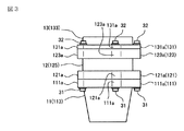
- 3 is a diagram schematically showing the appearance of the housing 10 (front housing 11, center housing 12, and rear housing 13) of the compressor 1, FIG.
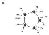
- FIG. 4 is a diagram viewed from the rear
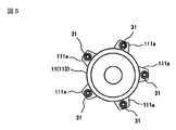
- FIG. 5 is a diagram viewed from the front. It is.
- the rear housing 13 has a joint end portion 131 and a body portion 133, and the rear side insertion portion 131 a in the rear housing 13 is more radial than the body portion 133. It is formed so as to protrude outward.
- the center housing 12 includes joining end portions 121 and 123 and a body portion 125, and the rear side screwing portion 123 a of the center housing 12 is formed so as to protrude outward in the radial direction from the body portion 125. .
- the fastening portion by the bolt 32 is outside the body portions 133 and 125 among the joining end portion 131 of the rear housing 13 and the joining end portion 123 on the rear end face 12b side of the center housing 12.
- the diameter of the pitch circle at the center of the bolt insertion hole 132 for the bolt 32 is set to be larger than the diameter of the body portion 133 of the rear housing 13.
- the front housing 11 has a joining end portion 111 and a body portion 113, and the front side insertion portion 111 a in the front housing 11 is radially outward from the body portion 113. It is formed to protrude.
- the front-side threaded portion 121 a of the center housing 12 is formed so as to protrude outward in the radial direction from the body portion 125 of the center housing 12. That is, in the present embodiment, only the fastening portion by the bolt 31 is outside the body portions 113 and 125 among the joint end portion 111 of the front housing 11 and the joint end portion 121 on the front end face 12a side of the center housing 12. It protrudes.
- the diameter of the pitch circle at the center of the bolt insertion hole 112 for the bolt 31 is set to be larger than the diameter of the body portion 113 of the front housing 11.
- the inner end surface 12b1 and the outer end surface 12b2 of the rear end surface 12b of the center housing 12 are formed flat on the same plane in a state where the load of the fastening force (pressing force) is released. .
- the rear end surface 12b of the center housing 12 is divided into the inner end surface 12b1 and the outer end surface 12b2, but in a state where the fastening force is not applied, it is a flat surface over the entire surface.
- the rear end surface 12b of the center housing 12 corresponds to “one of the joint surfaces” according to the invention. Therefore, the front end surface 13a of the rear housing 13 corresponds to “the other joint surface”.
- the outer end face 13a2 of the front end face 13a (the other joining face) of the rear housing 13 is in a state in which the load of the fastening force from the bolt 32 is released, as shown in FIGS.
- the outer end surface 13a2 is formed of, for example, a plane inclined with respect to the rear end surface (one joining surface) 12b of the center housing 12 in a state where the load of the fastening force is released.
- FIG. 1 a plane inclined with respect to the rear end surface (one joining surface) 12b of the center housing 12 in a state where the load of the fastening force is released.
- the inclination starting point of the outer end face 13a2 is inside the housing center side edge of the opening of the bolt insertion hole 132 of the rear side insertion part 131a (left side in the figure), that is, the drive shaft 42. It is set at a position close to the central axis side.
- the outer end surface 13a2 formed of an inclined plane is formed on the rear housing 13 side of the rear housing 13 and the center housing 12 that are joined to each other.
- the inclination starting point of this outer side end surface 13a2 is not restricted to this, For example, it is preferable that it is a position nearer to the inner side (left side in the figure) than the central axis of the bolt insertion hole 132. More specifically, as shown in FIG.
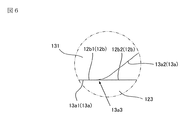
- FIG. 6 which is an enlarged view of a portion A shown in FIG. 2, a boundary portion 13a3 between the inner end surface 13a1 and the outer end surface 13a2 of the front end surface (joint surface) 13a of the rear housing 13 is shown. Is formed in an R shape in a state in which the load of the fastening force is released.
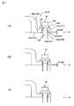
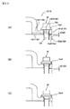
- FIG. 7 is a conceptual diagram for explaining a situation in which the rear side insertion portion 131a bends, and FIG.
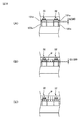
- FIGS. 8 is a conceptual diagram for explaining a change in surface pressure between adjacent bolts 32 at the time of bolt tightening.
- . 7A is a state before bolt tightening
- FIG. 7B is a state during bolt tightening
- FIG. 7C is the bolt tightening completed
- the entire front end surface (joint surface) 13a of the rear housing 13 is shown. That is, the entire inner end surface 13 a 1 and outer end surface 13 a 2 are in contact with the flat rear end surface 12 b of the center housing 12.
- FIGS. 8A, 8B, and 8C are views seen from the direction of the arrow X shown in FIGS. 7A, 7B, and 7C, respectively. .
- FIGS. 8A, 8B, and 8C are views seen from the direction of the arrow X shown in FIGS. 7A, 7B, and 7C, respectively. .
- an operator or the like joins both joint surfaces (the front end surface 13a and the rear end surface 12b) of the rear housing 13 and the center housing 12 together with bolts.
- Each bolt 32 is inserted through the insertion hole 132.
- Each bolt 32 is up to the point immediately before the head 32a is seated on the seat surface 13a4 formed on the end surface opposite to the outer end surface 13a2 formed of an inclined plane in the rear side insertion portion 131a by the operator or the like. Tightened. At this time, the inner end surface 13a1 of the rear housing 13 and the inner end surface 12b1 of the center housing 12 are in contact (joined).
- an initial gap G0 (G) is generated between the outer end surface 13a2 of the rear housing 13 and the outer end surface 12b2 of the center housing 12.
- the surface pressure P is not generated between both joint surfaces (the front end surface 13a and the rear end surface 12b).
- the surface pressure P in the region corresponding to the rear insertion portion 131a increases. Simultaneously with the increase in the surface pressure of the region corresponding to the rear side insertion portion 131a, as shown in FIG. 8B, the region corresponding to the adjacent bolts of both joint surfaces (the front end surface 13a and the rear end surface 12b). It has been experimentally confirmed that the surface pressure P also gradually increases and that the degree of nonuniformity of the surface pressure distribution in the circumferential direction of the inner end surfaces 13a1 and 12b1 gradually decreases.
- the surface pressure P in the region corresponding to the space between the adjacent bolts of the joint surfaces (front end surface 13a and rear end surface 12b) further increases, and the surface pressure distribution in the circumferential direction of the inner end surfaces 13a1 and 12b1.
- the degree of non-uniformity is reduced.
- the bolts 32 are tightened by an operator or the like until the outer end surface 13a2 of the rear side insertion portion 131a comes into contact with the outer end surface 12b2 of the center housing 12 and the gap G is eliminated.
- FIGS. 7C and 8C the fastening of the rear housing 13 and the center housing 12 with the bolts 32 is completed.
- a sufficient surface pressure is set in advance so as to be ensured between both the joining surfaces (the front end surface 13a and the rear end surface 12b).
- the diameter of the bolt insertion hole 132 is such that the neck portion of the bolt 32 is the inner wall surface of the bolt insertion hole 132 as shown in FIG. It is set not to touch.
- the rear housing 13 and the center housing 12 include a plurality of joint surfaces of the joint end portions 131 and 123 (specifically, both inner end surfaces 13a1 and 12b1) joined together. The bolts 32 are fastened to each other.
- the rear side insertion portion 131 a is set in a region corresponding to the outer end surface 13 a 2 in the joining end portion 131 of the rear housing 13.
- the rear side insertion portion 131a is A gap G is formed between the center housing 12 and the outer end surface 12b2.
- the rear side insertion portion 131a has elasticity that bends toward the center housing 12 side when the pressing force (fastening force) is applied.
- the joint surface (front end surface 13 a) of the rear housing 13 due to intrusion of salt water or the like between the rear housing 13 and the center housing 12 while suppressing an increase in manufacturing cost. And corrosion of the joint surface (rear end surface 12b) of the center housing 12, especially the joint surface between the bolts can be prevented or suppressed.
- the rear side insertion portion 131 a is formed so as to protrude outward in the radial direction from the body portion 133 of the rear housing 13. Thereby, since the rear side insertion part 131a can be bent easily, the structure which raises the surface pressure between adjacent volt
- the outer end surface 13a2 of the front end surface 13a (the other joint surface) of the rear housing 13 is the rear end surface of the center housing 12 as it goes radially outward in a state where the load of the fastening force is released. It is formed so as to be separated from 12b (one joint surface).
- the outer end surface 13a2 is configured to have a plane inclined with respect to the rear end surface 12b (one joining surface) in a state where the load of the fastening force is released. Thereby, the increase in the manufacturing cost for forming the outer side end surface 13a2 can be suppressed.
- the boundary portion 13a3 between the inner end surface 13a1 and the outer end surface 13a2 is formed in an R shape in a state where the load of the fastening force is released.
- boundary part 13a3 used as the fulcrum at the time of rear side insertion part 131a bending can be made into a smooth shape.
- the boundary portion 13a3 can be reliably brought into contact with the rear end surface 12b (one joining surface). Therefore, corrosion of the joint surface (front end surface 13a) of the rear housing 13 and the joint surface (rear end surface 12b) of the center housing 12 can be more reliably prevented.
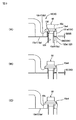
- FIG. 9 is an enlarged cross-sectional view showing a main part of a first modification of the compressor 1 and a conceptual diagram for explaining a situation where the rear side insertion portion 131a in the first modification is bent.
- the head portion 32a of the bolt 32 in the state where the fastening force is released (initial state), is opposite to the outer end surface 13a2 formed of an inclined plane in the rear side insertion portion 131a. It is in uniform contact with the seat surface 13a4 formed on the side end surface. However, the head portion 32a of the bolt 32 comes into a state where it comes into contact with the seating surface 13a4 as the rear side insertion portion 131a bends.
- the seat surface 13a4 when the bolt 32 is tightened and the rear side insertion portion 131a is bent, the seat surface 13a4 is substantially maintained in a state parallel to the outer end surface 13a2, while It approaches the end face 12b side. At this time, the inclination angle of the seat surface 13a4 with respect to the lower surface of the head portion 32a of the bolt 32 is reduced. 9C, the seating surface 13a4 is parallel to the outer end surface 13a2 and the rear end surface 12b. In this state, the lower surface of the head portion 32a of the bolt 32 is in contact with the seat surface 13a4 uniformly without contacting each other.
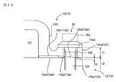
- FIG. 10 is an essential part enlarged cross-sectional view showing a second modification of the compressor 1.
- FIG. 11 is a conceptual diagram for explaining a situation where the rear side insertion portion 131a shown in FIG. 10 is bent.
- the inner end surface 12b1 and the outer end surface 12b2 of the joint surface (rear end surface 12b) of the center housing 12 are formed flat on the same plane in a state where the load of the fastening force is released.
- the present invention is not limited to this.
- the inner end surface 13a1 and the outer end surface 13a2 of the joining surface (front end surface 13a) of the rear housing 13 are in the same plane in a state in which the load of the fastening force is released. It is good also as a structure currently formed flatly.
- this modification 2 as shown in FIGS. 10 and 11, if the joint surface (rear end surface 12b) of the center housing 12 is formed so that the outer end surface 12b2 of the center housing 12 is inclined in the initial state. Good. That is, as shown in FIG. 10, the outer end surface 12b2 of the joint surface (rear end surface 12b) of the center housing 12 with the rear housing 13 is flatly joined to the rear housing 13 in a state where the load of the fastening force is released.
- the outer end surface (12b2 or 13a2) of the other joint surface (12b or 13a) has a diameter in a state in which the load of the fastening force is released. It can be set as the structure which consists of a plane inclined with respect to one joint surface (13a or 12b), so that it goes to the direction outer side. Moreover, in the said modification 2, similarly to the modification 1, the structure (modification 3) which eliminates the contact
- FIG. 12 is an enlarged cross-sectional view of a main part showing a third modification of the compressor 1 and a conceptual diagram for explaining a situation where the rear side insertion portion 131a in the third modification is bent.
- the seating surface 13a4 for contact with the head portion 32a of the bolt 32 is inclined with respect to the outer end surface 13a2 in the state where the load of the fastening force is released (initial state), and the fastening is performed.
- the inner end face 12b1 In a state where the gap G disappears due to force load (fastening completion state), the inner end face 12b1 is parallel. That is, in the initial state, the seating surface 13a4 is inclined to the opposite side of the inclined outer end surface 12b2, as shown in FIG.
- the seat surface 13a4 approaches the rear end surface 12b side. At this time, the inclination angle of the seat surface 13a4 with respect to the lower surface of the head portion 32a of the bolt 32 is reduced. And in the fastening completion state shown in FIG.12 (C), the seat surface 13a4 is parallel to the inner side end surface 12b1. In this state, the lower surface of the head portion 32a of the bolt 32 is in contact with the seat surface 13a4 uniformly without contacting each other.
- the outer end surfaces 13a2 and 12b2 are not limited to flat surfaces inclined in one direction, and may be curved surfaces in a state where the load of the fastening force is released.
- the rear housing 13 side is bent by the fastening force of the bolt 32.
- the present invention is not limited to this, and the center housing 12 side may be bent. That is, the “first housing member” according to the present invention is not limited to the rear housing 13 but may be the center housing 12. In this case, the rear housing 13 may be configured as a “second housing member” according to the present invention.
- the rear side insertion portion of the bolt 32 may be formed at the joint end portion 123 of the center housing 12, and the rear side screwing portion of the bolt 32 may be formed at the joint end portion 131 of the rear housing 13. Further, at the joint end portion 111 of the front housing 11 and the joint end portion 121 on the front end surface 12a side of the center housing 12, the joint end portion 131 of the rear housing 13 and the joint end portion 123 on the rear end surface 12b side of the center housing 12 are also provided.
- a similar configuration can be employed. That is, a bending structure for increasing the surface pressure P between adjacent bolts at the joining end portions 131 and 123 of the rear housing 13 and the center housing 12 may be adopted only on the rear side of the housing 10 or on the front side.
- the number of the bolts 31 and 32 can be set suitably. Further, the number of divisions and the divided parts of the housing 10 can be determined as appropriate, and the above-described bending structure may be appropriately adopted at the divided parts. Moreover, in this embodiment and each said modification, the joining end parts 111, 121, 123, 131 of each housing 11,12,13 are the insertion site
- the present invention is not limited to this, and all or a part of each of the joining end portions 111, 121, 123, 131 is formed into a flange shape over the whole without the corresponding portion between adjacent bolts being thinned. It may be formed. Even in this case, the rear side insertion part 131a, the front side insertion part 111a, etc. can be bent, and the fixed effect which raises the surface pressure P between adjacent volt
- the bolts 32 and 31 with a head were mentioned and demonstrated as an example of a fastening member, a fastening member is not restricted to this,
- the bolts 32 and 31 with a head It may be made of a nut, or may be made of a stud bolt and a nut without a head.
- this invention is not limited to the above-mentioned embodiment and modification, Further deformation
- transformation and change are possible based on the technical idea of this invention. It is.
Landscapes
- Engineering & Computer Science (AREA)
- Mechanical Engineering (AREA)
- General Engineering & Computer Science (AREA)
- Compressor (AREA)
- Applications Or Details Of Rotary Compressors (AREA)
- Rotary Pumps (AREA)
Abstract
複数のハウジング部材から構成されたハウジングを有する圧縮機において、製造コストの増加を抑制しつつ、各ハウジング部材の接合面の塩水等による腐食を防止する。 圧縮機1のハウジング10において、センターハウジング12及びリアハウジング13は、互いに接合面12b、13aが接合された状態で複数のボルト32により締結される。ボルト32のリア側挿通部位131aは、リアハウジング13の接合端部131のうちの外側端面13a2に対応する領域に設定される。ボルト32による締結力がリア側挿通部位131aに負荷されていない状態では、リア側挿通部位131aは、センターハウジング12の外側端面13a2との間に隙間Gを有する。リア側挿通部位は、前記締結力が負荷されると、センターハウジング12側に向かって橈む弾性を有する。
Description
本発明は、圧縮機に関し、特に複数のハウジング部材から構成されたハウジングを有する圧縮機に関する。
この種の圧縮機の一例として特許文献1に記載された圧縮機が知られている。特許文献1に記載された圧縮機において、ハウジングは、圧縮機構を収容するフロントケース、電動モータを収容するモータケース及び前記フロントケースと前記モータケースとの間に配置されたフレームからなり、これらがボルトによって互いに締結されて構成されている。前記フロントケースの端面(接合面)と前記フレームの一方の端面(接合面)との間や前記モータケースの端面(接合面)と前記フレームの他方の端面(接合面)との間は、それぞれOリングによってシールされている。
しかし、前記圧縮機において、ハウジングの各接合面のうちの隣り合うボルト間の接合面の面圧はボルト部位の接合面の面圧より低くなるため、塩水等がこのボルト間の接合面間を介して侵入し易くなる。したがって、このボルト間の接合面間への塩水等の侵入による各接合面の腐食を防止するためには、ボルト間の面圧を十分に確保する必要がある。このため、必要なボルト数が多くならざるを得ず、また、各ボルトの締め付けトルクの管理も必要であることから、製造コストが増加する傾向にあった。
そこで、本発明は、複数のハウジング部材から構成されたハウジングを有する圧縮機において、製造コストの増加を抑制しつつ、各ハウジング部材の接合面の塩水等による腐食を防止又は抑制することを目的とする。
そこで、本発明は、複数のハウジング部材から構成されたハウジングを有する圧縮機において、製造コストの増加を抑制しつつ、各ハウジング部材の接合面の塩水等による腐食を防止又は抑制することを目的とする。
本発明の一側面によると、ハウジングと前記ハウジング内に収容された圧縮機構とを含み、前記ハウジングが前記圧縮機構の駆動軸延伸方向に分割されている圧縮機であって、 前記ハウジングは、互いの接合端部の接合面同士が接合された状態で、複数の締結部材により互いに締結される第1ハウジング部材及び第2ハウジング部材を有し、前記第1ハウジング部材の接合面は、円環状の内側端面と、前記内側端面と連続して形成され前記内側端面よりも径方向外側に位置する外側端面とを含み、前記第2ハウジング部材の接合面は、前記第1ハウジング部材の前記内側端面と接合する円環状の内側端面と、この内側端面と連続して形成され前記第1ハウジング部材の前記外側端面と対向する外側端面とを含み、前記第1ハウジング部材の前記接合端部のうちの前記外側端面に対応する領域に、前記複数の締結部材の挿通部位が設定され、前記第1ハウジング部材の前記挿通部位は、前記締結部材による締結力が負荷されない状態で、前記第2ハウジング部材の前記外側端面との間に隙間を有し、前記締結力が負荷されると、前記第2ハウジング部材側に向かって撓む弾性を有する。
前記一側面による前記圧縮機においては、前記第1ハウジング部材及び前記第2ハウジング部材は、互いの接合端部の接合面同士が接合された状態で複数の締結部材により互いに締結されている。前記複数の締結部材の挿通部位は、前記第1ハウジング部材の前記接合端部のうちの前記外側端面に対応する領域に設定されている。そして、前記締結部材による締結力が前記第1ハウジング部材の前記挿通部位に負荷されていない状態では、前記挿通部位は、前記第2ハウジング部材の前記外側端面との間に隙間を有している。一方、前記挿通部位は、前記締結力が負荷されると、前記第2ハウジング部材側に向かって撓む弾性を有している。
ここで、前記圧縮機において、作業者等により、前記接合面同士を接合させると共に前記複数の締結部材を前記挿通部位に挿通させて仮締めするものとする。この仮締め状態では、前記第1ハウジング部材の前記内側端面と前記第2ハウジング部材の前記内側端面とが当接し、前記第1ハウジング部材の前記外側端面と前記第2ハウジング部材の前記外側端面との間には前記隙間が生じている。そして、この仮締め状態では、従来と同様に、少なくとも前記接合面のうちの隣り合う締結部材間に対応する領域においては十分な面圧が得られておらず、円環状の前記内側端面の周方向における面圧分布は不均一である。しかし、前記圧縮機において、この仮締め状態から締結部材が更に締め付けられると、前記第1ハウジング部材の前記挿通部位が更に撓み始めて前記隙間が徐々に小さくなり、その結果、前記挿通部位に対応する領域の面圧が上昇する。そして、この挿通部位に対応する領域の面圧上昇と同時に、前記接合面のうちの隣り合う締結部材間に対応する領域の面圧も徐々に上昇すること、及び、前記内側端面の周方向における面圧分布の不均一の程度が徐々に少なくなること、が実験的に確認された。このため、例えば、単に前記接合面同士を接合させて締結部材を締付けない初期状態での隙間の大きさを、その隙間が締め付けにより無くなったときに、十分な面圧が前記接合面に確保されるように予め設定すれば、単に前記隙間の有無を目視するだけで締結部材による締め付け程度を管理することができる。このため、締結部材の締め付けトルクの管理を緩めることができる。また、締結部材間に対応する領域の面圧を十分に確保することができるため、ボルト等の締結部材の本数を低減することができる。そして、面圧分布の均一化を図ることができる。
このようにして、前記圧縮機によれば、その製造コストの増加を抑制しつつ、前記第1ハウジング部材と前記第2ハウジングとの間への塩水等の侵入による前記第1ハウジング部材の接合面及び前記第2ハウジング部材の接合面の腐食を防止又は抑制することができる。
ここで、前記圧縮機において、作業者等により、前記接合面同士を接合させると共に前記複数の締結部材を前記挿通部位に挿通させて仮締めするものとする。この仮締め状態では、前記第1ハウジング部材の前記内側端面と前記第2ハウジング部材の前記内側端面とが当接し、前記第1ハウジング部材の前記外側端面と前記第2ハウジング部材の前記外側端面との間には前記隙間が生じている。そして、この仮締め状態では、従来と同様に、少なくとも前記接合面のうちの隣り合う締結部材間に対応する領域においては十分な面圧が得られておらず、円環状の前記内側端面の周方向における面圧分布は不均一である。しかし、前記圧縮機において、この仮締め状態から締結部材が更に締め付けられると、前記第1ハウジング部材の前記挿通部位が更に撓み始めて前記隙間が徐々に小さくなり、その結果、前記挿通部位に対応する領域の面圧が上昇する。そして、この挿通部位に対応する領域の面圧上昇と同時に、前記接合面のうちの隣り合う締結部材間に対応する領域の面圧も徐々に上昇すること、及び、前記内側端面の周方向における面圧分布の不均一の程度が徐々に少なくなること、が実験的に確認された。このため、例えば、単に前記接合面同士を接合させて締結部材を締付けない初期状態での隙間の大きさを、その隙間が締め付けにより無くなったときに、十分な面圧が前記接合面に確保されるように予め設定すれば、単に前記隙間の有無を目視するだけで締結部材による締め付け程度を管理することができる。このため、締結部材の締め付けトルクの管理を緩めることができる。また、締結部材間に対応する領域の面圧を十分に確保することができるため、ボルト等の締結部材の本数を低減することができる。そして、面圧分布の均一化を図ることができる。
このようにして、前記圧縮機によれば、その製造コストの増加を抑制しつつ、前記第1ハウジング部材と前記第2ハウジングとの間への塩水等の侵入による前記第1ハウジング部材の接合面及び前記第2ハウジング部材の接合面の腐食を防止又は抑制することができる。
以下、添付図面を参照して本発明の実施形態について説明する。
図1は、本発明の一実施形態に係る圧縮機の概略断面図である。本実施形態に係る圧縮機1は、例えば車両用空調装置の冷媒回路に組み込まれ、前記冷媒回路(詳しくはその低圧側)から吸入した冷媒を圧縮して前記冷媒回路(詳しくはその高圧側)に吐出する。圧縮機1は、概ね円柱状の外観を有するハウジング10と、ハウジング10に収容された圧縮機構20とを含む。
ハウジング10は、圧縮機構20の後述する駆動軸42の延伸方向に複数個(本実施形態では三つ)に分割されており、フロントハウジング11、センターハウジング12及びリアハウジング13を含む。
フロントハウジング11とセンターハウジング12とは、フロントハウジング11の後端面11aとセンターハウジング12の前端面12aとが図示省略の介装材を介して接合された状態で、周方向に間隔をあけて配置された複数のボルト31によって締結されている。したがって、フロントハウジング11及びセンターハウジング12は、互いの接合端部111、121の接合面(つまりフロントハウジング11の後端面11a及びセンターハウジング12の前端面12a)同士が接合された状態で、複数のボルト31により互いに締結されている。詳しくは、ボルト31は、フロントハウジング11の接合端部111において周方向に間隔をあけて開孔されたボルト挿通孔112を挿通している。そして、ボルト31は、センターハウジング12の前端面12a側の接合端部(つまりフロントハウジング11との接合端部)121に形成された雌ねじ122と螺合する。これにより、ボルト31は、その頭部31aとセンターハウジング12の前端面12a側の接合端部121との間にフロントハウジング11の接合端部111を挟持することにより、フロントハウジング11とセンターハウジング12を締結する。
センターハウジング12とリアハウジング13とは、センターハウジング12の後端面12bとリアハウジング13の前端面13aとが図示省略の介装材を介して接合された状態で、周方向に間隔をあけて配置された複数のボルト32によって締結されている。したがって、センターハウジング12及びリアハウジング13は、互いの接合端部123、131の接合面(つまりセンターハウジング12の後端面12b及びリアハウジング13の前端面13a)同士が接合された状態で、複数のボルト32により互いに締結されている。詳しくは、ボルト32は、リアハウジング13の接合端部131において周方向に間隔をあけて開孔されたボルト挿通孔132を挿通している。そして、ボルト32は、センターハウジング12の後端面12b側の接合端部(つまりリアハウジング13との接合端部)123に形成された雌ねじ124と螺合する。これにより、ボルト32は、その頭部32aとセンターハウジング12の後端面12b側の接合端部123と間にリアハウジング13の接合端部131を挟持することにより、センターハウジング12とリアハウジング13を締結する。本実施形態において、前記ボルト32が本発明に係る「締結部材」に相当する。
なお、図1は、センターハウジング12とリアハウジング13とがボルト32により締め付けられておらず、センターハウジング12とリアハウジング13との接合面間に面圧が発生していない状態を示しているものとする。後述する図2、図6、図7(A)、図8(A)、図9(A)、図10、図11(A)及び図12(A)も同様である。また、前記介装材は、特に制限されないが、例えばOリング、ガスケット(液体ガスケットを含む)が該当する。
ハウジング10内には、吸入室C1と吐出室C2とが設けられている。吸入室C1は、フロントハウジング11とセンターハウジング12とによって形成されている。吸入室C1は、フロントハウジング11に形成された図示省略の吸入ポートを介して前記冷媒回路(の低圧側)に連通している。吐出室C2は、センターハウジング12とリアハウジング13とによって形成されている。吐出室C2は、リアハウジング13に形成された図示省略の吐出ポートを介して前記冷媒回路(の高圧側)に連通している。
圧縮機構20は、前記冷媒回路(の低圧側)から前記吸入ポートを介して吸入室C1に導かれた冷媒を圧縮する。圧縮機構20は、スクロール型圧縮機構であり、固定スクロール21及び可動スクロール22を含む。固定スクロール21は、台板部211と、台板部211の一方の面に形成(立設)された渦巻きラップ212とを有する。同様に、可動スクロール22は、台板部221と、台板部221の一方の面に形成(立設)された渦巻きラップ222とを有する。固定スクロール21と可動スクロール22とは、互いの渦巻きラップ212、222が噛み合うように配置されている。そして、両渦巻きラップ212、222の側壁が部分的に接触することによって両渦巻きラップ212、222の間に密閉空間としての圧縮室C3が形成される。
本実施形態において、固定スクロール21は、センターハウジング12と一体的に構成されている。すなわち、センターハウジング12は、前端を開口端とし、後端を閉鎖端とする有底円筒状に形成され、センターハウジング12の後端壁(底壁)が固定スクロール21の台板部211を構成している。また、固定スクロール21の台板部211のほぼ中央には、貫通孔213が形成されている。貫通孔213は、圧縮機構20によって圧縮された冷媒を吐出室C2に吐出するための吐出孔として機能するものであり、リード弁(吐出弁)214によって開閉される。
可動スクロール22は、クランク機構41を介して駆動軸42に連結されている。クランク機構41は、駆動軸42の回転運動を可動スクロール22の旋回運動に変換するように構成されている。このような機能を有するクランク機構は公知であるので、その詳細な説明は省略するが、クランク機構41は、例えば特開2013−160187号公報に記載された従動クランク機構と同様の構成を有するものであり得る。なお、可動スクロール22は、自転阻止機構43によってその自転が阻止されている。
駆動軸42のクランク機構41(可動スクロール22)側とは反対側の端部42aは、フロントハウジング11の外に突出しており、この突出した駆動軸42の端部42aに、電磁クラッチ51を介してプーリ52が接続されている。プーリ52は、回転自在に設けられており、図示省略のベルトを介して駆動源(前記車両のエンジンやモータ)側の出力プーリ(図示省略)に連結されている。
圧縮機1において、前記出力プーリの回転に伴うプーリ52の回転が電磁クラッチ51を介して駆動軸42に伝達されると、駆動軸42が回転する。駆動軸42の回転は、クランク機構41によって可動スクロール22の旋回運動に変換され、これにより、可動スクロール22は固定スクロール21に対して旋回運動を行う。可動スクロール22が旋回運動を行うと、両渦巻きラップ212、222によって両渦巻きラップ212、222の外側端部の近傍に圧縮室C3が形成され、その際、前記冷媒回路(の低圧側)から前記吸入ポートを介して吸入室C1に導かれた冷媒が圧縮室C3に取り込まれる。冷媒を取り込んだ圧縮室C3は、その後、その容積を減少させつつ、両渦巻きラップ212、222の内側端部、すなわち、台板部211、221の中央部に向かって移動する。これにより、圧縮室C3内の冷媒が圧縮される。そして、圧縮室C3内で圧縮された冷媒は、貫通孔(吐出孔)213及びリード弁214を介して吐出室C2に吐出され、その後、前記吐出ポートを介して前記冷媒回路(の高圧側)に吐出される。
ここで、圧縮機1において、リアハウジング13の前端面(つまり、センターハウジング12との接合面)13aは、これに対向するセンターハウジング12の後端面(つまり、リアハウジング13との接合面)12bに対して平行で且つ円環状の内側端面13a1と、この内側端面13a1と連続して形成され内側端面13a1よりも径方向外側に位置する外側端面13a2とを含む。なお、本実施形態では、リアハウジング13が本発明に係る「第1ハウジング部材」に相当する。
また、センターハウジング12の後端面12bは、リアハウジング13の内側端面13a1と接合する円環状の内側端面12b1と、この内側端面12b1に連続して形成されリアハウジング13の外側端面13a2と対向する外側端面12b2とを含む。なお、本実施形態では、センターハウジング12が本発明に係る「第2ハウジング部材」に相当する。
圧縮機1において、リアハウジング13のボルト32の挿通部位131aは、締結部材としてのボルト32による締結力が負荷されない状態で、センターハウジング12の外側端面12b2との間に隙間Gを有し、前記締結力が負荷されると、センターハウジング12側に向かって撓む弾性を有する。詳しくは、リアハウジング13における複数のボルト32の挿通部位(以下において「リア側挿通部位」という)131aは、ボルト32の頭部32aによるセンターハウジング12方向への押圧力が負荷されない状態で、その外側端面13a2とセンターハウジング12の外側端面12b2との間に隙間Gを有し、前記押圧力が負荷されると、センターハウジング12側に向かって撓む弾性を有するように構成されている。以下では、主に、リア側挿通部位131aの構造等に関する事項について詳述する。
図2は、センターハウジング12とリアハウジング13とを締結するボルト32を含む要部拡大断面図である。図1では、作図上の都合により、リアハウジング13の接合端部131の厚さt1を実際よりも厚くして示したが、この厚さt1は、例えば、センターハウジング12のリアハウジング側の接合端部123の厚さt2より薄くなるように形成されていればよい。具体的には、リアハウジング13の接合端部131の厚さt1は、図2に示すように、頭部32aの高さと同程度、若しくは、頭部32aの高さより小さくなるように形成するとよい。
図1及び図2に示すように、リアハウジング13の接合端部131のうちの外側端面13a2に対応する領域に、リア側挿通部位131aが設定されている。つまり、ボルト32用のボルト挿通孔132は、外側端面13a2を貫通している。また、センターハウジング12の後端面12b側の接合端部123のうちのボルト32用の雌ねじ124が形成されている部位を、以下においてリア側螺合部位123aという。そして、フロントハウジング11の接合端部111のうちのボルト31用のボルト挿通孔112が開口されている部位を、フロント側挿通部位111aといい、センターハウジング12の前端面12a側の接合端部121のうちのボルト31用の雌ねじ122が形成されている部位を、フロント側螺合部位121aという。
図3は、圧縮機1のハウジング10(フロントハウジング11、センターハウジング12及びリアハウジング13)の外観を模式的に示した図、図4は後方から視た図、図5は前方から視た図である。
本実施形態では、図3及び図4に示すように、リアハウジング13は、接合端部131と胴部133とを有し、リアハウジング13におけるリア側挿通部位131aが胴部133よりも径方向外側に突出するように形成されている。そして、センターハウジング12は、接合端部121、123と胴部125とを有し、センターハウジング12のリア側螺合部位123aが胴部125よりも径方向外側に突出するように形成されている。つまり、本実施形態では、リアハウジング13の接合端部131及びセンターハウジング12の後端面12b側の接合端部123のうち、ボルト32による締結箇所のみが、各胴部133、125よりも外側にそれぞれ突出している。また、本実施形態では、ボルト32用のボルト挿通孔132の孔中心のピッチ円の直径は、リアハウジング13の胴部133の直径よりも大きくなるように設定されている。
同様に、図3及び図5に示すように、フロントハウジング11は、接合端部111と胴部113とを有し、フロントハウジング11におけるフロント側挿通部位111aが胴部113よりも径方向外側に突出するように形成されている。そして、センターハウジング12のフロント側螺合部位121aは、センターハウジング12の胴部125よりも径方向外側に突出するように形成されている。つまり、本実施形態では、フロントハウジング11の接合端部111及びセンターハウジング12の前端面12a側の接合端部121のうち、ボルト31による締結箇所のみが、各胴部113、125よりも外側に突出している。また、本実施形態では、ボルト31用のボルト挿通孔112の孔中心のピッチ円の直径は、フロントハウジング11の胴部113の直径よりも大きくなるように設定されている。
また、本実施形態では、センターハウジング12の後端面12bにおける内側端面12b1及び外側端面12b2は、前記締結力(押圧力)の負荷が解除された状態で、同一平面上で平坦に形成されている。つまり、センターハウジング12の後端面12bは、内側端面12b1と外側端面12b2とに区分されているが、前記締結力が負荷されていない状態では、全体に亘って平坦な一平面である。本実施形態では、センターハウジング12の後端面12bが本発明に係る「一方の前記接合面」に相当する。したがって、リアハウジング13の前端面13aが「他方の前記接合面」に相当する。
そして、本実施形態では、リアハウジング13の前端面13a(他方の接合面)における外側端面13a2は、図1及び図2に示すように、ボルト32からの前記締結力の負荷が解除された状態で、径方向外側に向かうほどセンターハウジング12の後端面(一方の接合面)12bから離れるように形成されている。
具体的には、外側端面13a2は、例えば、前記締結力の負荷が解除された状態で、センターハウジング12の後端面(一方の接合面)12bに対して傾斜した平面からなる。この外側端面13a2の傾斜起点は、例えば、図2に示すように、リア側挿通部位131aのボルト挿通孔132の開口のハウジング中心側縁部よりも内側(図中左側)、つまり、駆動軸42の中心軸側に寄せた位置に設定されている。このように、本実施形態では、傾斜した平面からなる外側端面13a2は、互いに接合されるリアハウジング13及びセンターハウジング12のうちのリアハウジング13側に形成されている。なお、この外側端面13a2の傾斜起点は、これに限らず、例えば、ボルト挿通孔132の中心軸よりも内側(図中左側)に寄せた位置であることが好ましい。
より具体的には、図2に示すA部の拡大図である図6に示すように、リアハウジング13の前端面(接合面)13aにおいて、その内側端面13a1と外側端面13a2との境界部位13a3は、前記締結力の負荷が解除された状態で、R形状になるように形成されている。
次に、ボルト32の締め付け時におけるリア側挿通部位131aの変形、及び、隣り合うボルト32間の面圧の変化について、図7及び図8を参照して説明する。図7は、リア側挿通部位131aが撓む状況を説明するための概念図であり、図8は、ボルト締め付け時における隣り合うボルト32間の面圧の変化を説明するための概念図である。図7(A)はボルト締め付け前の状態、図7(B)はボルト締め付け中の状態、図7(C)はボルト締め付けが完了し、リアハウジング13の前端面(接合面)13aの全体、つまり、内側端面13a1及び外側端面13a2の全体がセンターハウジング12の平坦な後端面12bに当接している状態を示している。図8(A)、図8(B)及び図8(C)は、それぞれ、図7(A)、図7(B)及び図7(C)に示すX矢視方向から視た図である。
まず、図7(A)及び図8(A)に示すように、作業者等により、リアハウジング13及びセンターハウジング12の両接合面(前端面13a及び後端面12b)同士を接合させると共に、ボルト挿通孔132を介して各ボルト32を挿通させる。そして、各ボルト32は、作業者等により、その頭部32aがリア側挿通部位131aにおける傾斜した平面からなる外側端面13a2と反対側の端面に形成される座面13a4に着座する直前のところまで締め付けられる。このとき、リアハウジング13の内側端面13a1とセンターハウジング12の内側端面12b1が当接(接合)している。一方、リアハウジング13の外側端面13a2とセンターハウジング12の外側端面12b2との間には、初期隙間G0(G)が生じている。このとき、両接合面(前端面13a及び後端面12b)間には、面圧Pは発生していない。
次に、図7(A)及び図8(A)に示す初期状態から、作業者等により、各ボルト32が更に締め付けられると、図7(B)及び図8(B)に示す仮締め状態になる。つまり、前記初期状態からボルト32が更に締め付けられると、図7(B)及び図8(B)に示すように、リアハウジング13のリア側挿通部位131aが撓み始めて隙間Gが徐々に小さくなる。その結果、リア側挿通部位131aに対応する領域の面圧Pが上昇する。このリア側挿通部位131aに対応する領域の面圧上昇と同時に、図8(B)に示すように、両接合面(前端面13a及び後端面12b)のうちの隣り合うボルト間に対応する領域の面圧Pも徐々に上昇すること、及び、内側端面13a1、12b1の周方向における面圧分布の不均一の程度が徐々に少なくなること、が実験的に確認された。しかし、この仮締めした状態では、従来と同様に、少なくとも両接合面のうちの隣り合うボルト間に対応する領域においては十分な面圧が得られていないと共に、円環状の内側端面13a1、12b1の周方向における面圧分布は不均一である。
そして、図7(B)及び図8(B)に示す仮締め状態から、作業者等により、各ボルト32が更に締め付けられると、リア側挿通部位131aが更に撓んで、隙間Gが更に小さくなり、その結果、リア側挿通部位131aに対応する領域の面圧が更に上昇する。そしてこれと同時に、両接合面(前端面13a及び後端面12b)のうちの隣り合うボルト間に対応する領域の面圧Pが更に上昇すると共に、内側端面13a1、12b1の周方向における面圧分布の不均一の程度が小さくなる。そして、作業者等により、各ボルト32が、リア側挿通部位131aの外側端面13a2がセンターハウジング12の外側端面12b2に当接し、隙間Gが無くなるところまで締め付けられる。これにより、図7(C)及び図8(C)に示すように、リアハウジング13とセンターハウジング12とのボルト32による締結が完了する。この締結完了状態において、両接合面(前端面13a及び後端面12b)のボルト間を含めた全体に亘って十分な面圧Pが得られていると共に、内側端面13a1、12b1の周方向における面圧分布の不均一の程度が更に小さくなっている。このように、リア側挿通部位131aの撓み量が増加するにしたがって、リア側挿通部位131aに対応する領域の面圧Pが上昇すると共に、隣り合うボルト間の面圧Pも上昇する。
なお、本実施形態では、前記初期状態(図7(A)及び図8(A)で示す状態)での初期隙間G0の大きさを、その隙間Gがボルト締め付けにより無くなったとき(図7(C)及び図8(C)で示す状態のとき)に、十分な面圧が両接合面間(前端面13a及び後端面12b)に確保されるように予め設定されている。また、ボルト挿通孔132の孔径は、リア側挿通部位131aが撓んでセンターハウジング12に当接した状態で、図7(C)に示すように、ボルト32の首部がボルト挿通孔132の内壁面に接触しないように設定されている。
本実施形態に係る圧縮機1においては、リアハウジング13及びセンターハウジング12は、互いの接合端部131、123の両接合面(詳しくは両内側端面13a1、12b1)同士が接合された状態で複数のボルト32により互いに締結されている。リア側挿通部位131aは、リアハウジング13の接合端部131のうちの外側端面13a2に対応する領域に設定されている。そして、ボルト32の頭部32aによるセンターハウジング12方向への押圧力(つまり、締結部材による締結力)がリアハウジング13のリア側挿通部位131aに負荷されていない状態では、リア側挿通部位131aは、センターハウジング12の外側端面12b2との間に隙間Gを有している。一方、リア側挿通部位131aは、前記押圧力(締結力)が負荷されると、センターハウジング12側に向かって撓む弾性を有している。
この圧縮機1においては、リア側挿通部位131aの撓み量が増加するにしたがって、リア側挿通部位131aに対応する領域の面圧Pが上昇すると共に隣り合うボルト間の面圧Pも上昇し、且つ、内側端面13a1、12b1の周方向における面圧分布の不均一の程度が小さくなることが確認された。したがって、例えば、接合面同士を接合させてボルト32を締付けない初期状態での初期隙間G0の大きさを、その隙間Gがボルト締め付けにより無くなったときに、十分な面圧Pが接合面に確保されるように予め設定することにより、単に隙間Gの有無を目視するだけでボルト32による締め付け程度を管理することができる。このため、ボルト32の締め付けトルクの管理を緩めることができる。また、ボルト間に対応する領域の面圧Pを十分に確保することができるため、ボルト32の本数を低減することができる。そして、面圧分布の均一化を図ることができる。
このようにして、圧縮機1によれば、その製造コストの増加を抑制しつつ、リアハウジング13とセンターハウジング12との間への塩水等の侵入によるリアハウジング13の接合面(前端面13a)及びセンターハウジング12の接合面(後端面12b)、特にボルト間の接合面の腐食を防止又は抑制することができる。
本実施形態では、リア側挿通部位131aは、リアハウジング13の胴部133よりも径方向外側に突出するように形成されている。これにより、リア側挿通部位131aを容易に撓ませることができるため、隣り合うボルト間の面圧を上昇させる構造を容易に構築することができる。
また、本実施形態では、リアハウジング13の前端面13a(他方の接合面)における外側端面13a2は、前記締結力の負荷が解除された状態で、径方向外側に向かうほどセンターハウジング12の後端面12b(一方の接合面)から離れるように形成されている。これにより、前記締結力の増加に追従して撓み量が適切に増加し、その結果、面圧Pが適切に上昇する構造を容易に構築することができる。
また、本実施形態では、外側端面13a2は、前記締結力の負荷が解除された状態で、後端面12b(一方の接合面)に対して傾斜した平面からなる構成とした。これにより、外側端面13a2を形成するための製造コストの増加を抑制することができる。
また、本実施形態では、内側端面13a1と外側端面13a2との境界部位13a3は、前記締結力の負荷が解除された状態で、R形状に形成されている。これにより、リア側挿通部位131aが撓む際の支点となる境界部位13a3を滑らかな形状にすることができる。その結果、この境界部位13a3においても確実に後端面12b(一方の接合面)に当接させることができる。したがって、リアハウジング13の接合面(前端面13a)及びセンターハウジング12の接合面(後端面12b)の腐食をより確実に防止することができる。
次に、上述の実施形態のいくつかの変形例(変形例1~変形例3)について説明する。なお、以下の各変形例は適宜組み合わせることが可能である。
図9は、圧縮機1の変形例1を示す要部拡大断面図であると共に、この変形例1におけるリア側挿通部位131aが撓む状況を説明するための概念図である。
上記実施形態では、図2に示すように、前記締結力が解除された状態(初期状態)では、ボルト32の頭部32aは、リア側挿通部位131aにおける傾斜した平面からなる外側端面13a2と反対側の端面に形成された座面13a4に、均一に当接している。しかし、ボルト32の頭部32aは、リア側挿通部位131aが撓むにつれて、座面13a4に片あたりする状態になる。そして、隙間Gが無くなった圧縮機1の使用状態において、この片あたり状態は維持されることになる。
このため、変形例1では、ボルト32の頭部32aの当接用の座面13a4は、前記締結力の負荷が解除された状態(初期状態)では、外側端面13a2と平行であり、且つ、前記締結力の負荷により隙間Gが無くなった状態(締結完了状態)では、外側端面13a2及び後端面12b(一方の接合面)と平行である構成とした。つまり、座面13a4は、初期状態では、図9(A)に示すように、傾斜した外側端面13a2と同様に傾斜しており、ボルト32の頭部32aと片あたりしている。この片あたり状態から、図9(B)に示すように、ボルト32が締め付けられてリア側挿通部位131aが撓むと、座面13a4は、外側端面13a2と平行な状態を略維持しつつ、後端面12b側に近づく。このとき、ボルト32の頭部32aの下面に対する座面13a4の傾斜角は小さくなる。そして、図9(C)に示す締結完了状態では、座面13a4は、外側端面13a2及び後端面12bと平行である。この状態で、ボルト32の頭部32aの下面は、座面13a4に、片あたりすることなく全体に亘って均一に当接する。これにより、この圧縮機1の使用状態において、ボルト32の頭部32aを座面13a4に片あたりさせることなく、均一に当接させることができる。
図10は、圧縮機1の変形例2を示す要部拡大断面図である。図11は、図10に示すリア側挿通部位131aが撓む状況を説明するための概念図である。
上記実施形態及び変形例1では、センターハウジング12の接合面(後端面12b)における内側端面12b1及び外側端面12b2が、前記締結力の負荷が解除された状態で、同一平面上で平坦に形成されている場合を一例に挙げて説明したが、これに限らない。図10及び図11に示した変形例2のように、リアハウジング13の接合面(前端面13a)における内側端面13a1及び外側端面13a2が、前記締結力の負荷が解除された状態で、同一平面上で平坦に形成されている構成としてもよい。
この変形例2の場合、図10及び図11に示すように、センターハウジング12における外側端面12b2が初期状態において傾斜しているように、センターハウジング12の接合面(後端面12b)を形成すればよい。
つまり、図10に示すように、センターハウジング12のリアハウジング13との接合面(後端面12b)における外側端面12b2が、前記締結力の負荷が解除された状態で、リアハウジング13の平坦な接合面(前端面13a)に対して傾斜した平面からなる構成とすればよい。この場合、図11(A)~図11(C)に示すように、ボルト32の締め付けに応じて、リア側挿通部位131aが撓み、初期状態での隙間Gが徐々に小さくなって、図11(C)では隙間Gが無くなる。このように、圧縮機1において、リアハウジング13及びセンターハウジング12のいずれか一方の接合面(13a又は12b)における内側端面(13a1又は12b1)及び外側端面(13a2又は12b2)が、前記締結力の負荷が解除された状態で、同一平面上で平坦に形成されており、他方の接合面(12b又は13a)における外側端面(12b2又は13a2)が、前記締結力の負荷が解除された状態で径方向外側に向かうほど一方の接合面(13a又は12b)に対して傾斜した平面からなる構成とすることができる。
また、上記変形例2において、変形例1と同様に、圧縮機1の使用状態におけるボルト32の頭部32aの座面13a4への片あたりを解消させる構成(変形例3)を採用してもよい。図12は、圧縮機1の変形例3を示す要部拡大断面図であると共に、この変形例3におけるリア側挿通部位131aが撓む状況を説明するための概念図である。
変形例3では、ボルト32の頭部32aの当接用の座面13a4は、前記締結力の負荷が解除された状態(初期状態)では、外側端面13a2に対して傾斜し、且つ、前記締結力の負荷により隙間Gが無くなった状態(締結完了状態)では、内側端面12b1と平行である構成とした。つまり、座面13a4は、初期状態では、図12(A)に示すように、傾斜した外側端面12b2と反対側に傾斜しており、ボルト32の頭部32aと片あたりしている。この片あたり状態から、図12(B)に示すように、ボルト32が締め付けられてリア側挿通部位131aが撓むと、座面13a4は、後端面12b側に近づく。このとき、ボルト32の頭部32aの下面に対する座面13a4の傾斜角は小さくなる。そして、図12(C)に示す締結完了状態では、座面13a4は、内側端面12b1と平行である。この状態で、ボルト32の頭部32aの下面は、座面13a4に、片あたりすることなく全体に亘って均一に当接する。
また、外側端面13a2、12b2は、一方向に傾斜した平面に限らず、前記締結力の負荷が解除された状態で、湾曲した曲面からなるものとしてもよい。
また、本実施形態では、ボルト32の締結力により、リアハウジング13側が撓む構成としたが、これに限らず、センターハウジング12側が撓む構成としてもよい。つまり、本発明に係る「第1ハウジング部材」はリアハウジング13に限らずセンターハウジング12であってもよい。この場合、リアハウジング13を本発明に係る「第2ハウジング部材」として構成すればよい。具体的には、センターハウジング12の接合端部123にボルト32のリア側挿通部位を形成し、リアハウジング13の接合端部131にボルト32のリア側螺合部位を形成すればよい。
さらに、フロントハウジング11の接合端部111とセンターハウジング12の前端面12a側の接合端部121においても、リアハウジング13の接合端部131とセンターハウジング12の後端面12b側の接合端部123と同様の構成を採用することができる。つまり、リアハウジング13及びセンターハウジング12の接合端部131、123における隣り合うボルト間の面圧Pを上昇させるための撓み構造を、ハウジング10のリア側だけに採用してもよいし、フロント側にだけ採用してもよいし、リア及びフロントの両側に採用してもよい。また、ボルト31、32の本数は適宜設定することができる。さらに、ハウジング10の分割数及び分割部位は適宜に定めることができ、その分割部位において、上記撓み構造を適宜に採用すればよい。
また、本実施形態及び上記各変形例では、各ハウジング11、12、13の接合端部111、121、123、131は、ボルト31、32の挿通部位及び螺合部位(例えば、リア側挿通部位131a、フロント側挿通部位111a、リア側螺合部位123a、フロント側螺合部位121a)のみが各胴部113、125、133よりも径方向外側に突出するように形成される構成とした。しかし、これに限らず、各接合端部111、121、123、131の全部又はその一部は、隣り合うボルト間に対応する部位が肉抜きされずに、全体に亘ってフランジ状になるように形成されていてもよい。この場合であっても、リア側挿通部位131aやフロント側挿通部位111a等を撓ませて、隣り合うボルト間の面圧Pを上昇させる一定の効果を奏することができる。
また、本実施形態及び上記各変形例では、締結部材の一例として頭部付きのボルト32、31を挙げて説明したが、締結部材は、これに限らず、頭部付きのボルト32、31とナットからなるものとしてもよいし、頭部の無いスタッドボルトとナットからなるものとしてもよい。
以上、本発明の実施形態及びその変形例について説明したが、本発明は上述の実施形態や変形例に限定されるものではなく、本発明の技術的思想に基づいて更なる変形や変更が可能である。
図1は、本発明の一実施形態に係る圧縮機の概略断面図である。本実施形態に係る圧縮機1は、例えば車両用空調装置の冷媒回路に組み込まれ、前記冷媒回路(詳しくはその低圧側)から吸入した冷媒を圧縮して前記冷媒回路(詳しくはその高圧側)に吐出する。圧縮機1は、概ね円柱状の外観を有するハウジング10と、ハウジング10に収容された圧縮機構20とを含む。
ハウジング10は、圧縮機構20の後述する駆動軸42の延伸方向に複数個(本実施形態では三つ)に分割されており、フロントハウジング11、センターハウジング12及びリアハウジング13を含む。
フロントハウジング11とセンターハウジング12とは、フロントハウジング11の後端面11aとセンターハウジング12の前端面12aとが図示省略の介装材を介して接合された状態で、周方向に間隔をあけて配置された複数のボルト31によって締結されている。したがって、フロントハウジング11及びセンターハウジング12は、互いの接合端部111、121の接合面(つまりフロントハウジング11の後端面11a及びセンターハウジング12の前端面12a)同士が接合された状態で、複数のボルト31により互いに締結されている。詳しくは、ボルト31は、フロントハウジング11の接合端部111において周方向に間隔をあけて開孔されたボルト挿通孔112を挿通している。そして、ボルト31は、センターハウジング12の前端面12a側の接合端部(つまりフロントハウジング11との接合端部)121に形成された雌ねじ122と螺合する。これにより、ボルト31は、その頭部31aとセンターハウジング12の前端面12a側の接合端部121との間にフロントハウジング11の接合端部111を挟持することにより、フロントハウジング11とセンターハウジング12を締結する。
センターハウジング12とリアハウジング13とは、センターハウジング12の後端面12bとリアハウジング13の前端面13aとが図示省略の介装材を介して接合された状態で、周方向に間隔をあけて配置された複数のボルト32によって締結されている。したがって、センターハウジング12及びリアハウジング13は、互いの接合端部123、131の接合面(つまりセンターハウジング12の後端面12b及びリアハウジング13の前端面13a)同士が接合された状態で、複数のボルト32により互いに締結されている。詳しくは、ボルト32は、リアハウジング13の接合端部131において周方向に間隔をあけて開孔されたボルト挿通孔132を挿通している。そして、ボルト32は、センターハウジング12の後端面12b側の接合端部(つまりリアハウジング13との接合端部)123に形成された雌ねじ124と螺合する。これにより、ボルト32は、その頭部32aとセンターハウジング12の後端面12b側の接合端部123と間にリアハウジング13の接合端部131を挟持することにより、センターハウジング12とリアハウジング13を締結する。本実施形態において、前記ボルト32が本発明に係る「締結部材」に相当する。
なお、図1は、センターハウジング12とリアハウジング13とがボルト32により締め付けられておらず、センターハウジング12とリアハウジング13との接合面間に面圧が発生していない状態を示しているものとする。後述する図2、図6、図7(A)、図8(A)、図9(A)、図10、図11(A)及び図12(A)も同様である。また、前記介装材は、特に制限されないが、例えばOリング、ガスケット(液体ガスケットを含む)が該当する。
ハウジング10内には、吸入室C1と吐出室C2とが設けられている。吸入室C1は、フロントハウジング11とセンターハウジング12とによって形成されている。吸入室C1は、フロントハウジング11に形成された図示省略の吸入ポートを介して前記冷媒回路(の低圧側)に連通している。吐出室C2は、センターハウジング12とリアハウジング13とによって形成されている。吐出室C2は、リアハウジング13に形成された図示省略の吐出ポートを介して前記冷媒回路(の高圧側)に連通している。
圧縮機構20は、前記冷媒回路(の低圧側)から前記吸入ポートを介して吸入室C1に導かれた冷媒を圧縮する。圧縮機構20は、スクロール型圧縮機構であり、固定スクロール21及び可動スクロール22を含む。固定スクロール21は、台板部211と、台板部211の一方の面に形成(立設)された渦巻きラップ212とを有する。同様に、可動スクロール22は、台板部221と、台板部221の一方の面に形成(立設)された渦巻きラップ222とを有する。固定スクロール21と可動スクロール22とは、互いの渦巻きラップ212、222が噛み合うように配置されている。そして、両渦巻きラップ212、222の側壁が部分的に接触することによって両渦巻きラップ212、222の間に密閉空間としての圧縮室C3が形成される。
本実施形態において、固定スクロール21は、センターハウジング12と一体的に構成されている。すなわち、センターハウジング12は、前端を開口端とし、後端を閉鎖端とする有底円筒状に形成され、センターハウジング12の後端壁(底壁)が固定スクロール21の台板部211を構成している。また、固定スクロール21の台板部211のほぼ中央には、貫通孔213が形成されている。貫通孔213は、圧縮機構20によって圧縮された冷媒を吐出室C2に吐出するための吐出孔として機能するものであり、リード弁(吐出弁)214によって開閉される。
可動スクロール22は、クランク機構41を介して駆動軸42に連結されている。クランク機構41は、駆動軸42の回転運動を可動スクロール22の旋回運動に変換するように構成されている。このような機能を有するクランク機構は公知であるので、その詳細な説明は省略するが、クランク機構41は、例えば特開2013−160187号公報に記載された従動クランク機構と同様の構成を有するものであり得る。なお、可動スクロール22は、自転阻止機構43によってその自転が阻止されている。
駆動軸42のクランク機構41(可動スクロール22)側とは反対側の端部42aは、フロントハウジング11の外に突出しており、この突出した駆動軸42の端部42aに、電磁クラッチ51を介してプーリ52が接続されている。プーリ52は、回転自在に設けられており、図示省略のベルトを介して駆動源(前記車両のエンジンやモータ)側の出力プーリ(図示省略)に連結されている。
圧縮機1において、前記出力プーリの回転に伴うプーリ52の回転が電磁クラッチ51を介して駆動軸42に伝達されると、駆動軸42が回転する。駆動軸42の回転は、クランク機構41によって可動スクロール22の旋回運動に変換され、これにより、可動スクロール22は固定スクロール21に対して旋回運動を行う。可動スクロール22が旋回運動を行うと、両渦巻きラップ212、222によって両渦巻きラップ212、222の外側端部の近傍に圧縮室C3が形成され、その際、前記冷媒回路(の低圧側)から前記吸入ポートを介して吸入室C1に導かれた冷媒が圧縮室C3に取り込まれる。冷媒を取り込んだ圧縮室C3は、その後、その容積を減少させつつ、両渦巻きラップ212、222の内側端部、すなわち、台板部211、221の中央部に向かって移動する。これにより、圧縮室C3内の冷媒が圧縮される。そして、圧縮室C3内で圧縮された冷媒は、貫通孔(吐出孔)213及びリード弁214を介して吐出室C2に吐出され、その後、前記吐出ポートを介して前記冷媒回路(の高圧側)に吐出される。
ここで、圧縮機1において、リアハウジング13の前端面(つまり、センターハウジング12との接合面)13aは、これに対向するセンターハウジング12の後端面(つまり、リアハウジング13との接合面)12bに対して平行で且つ円環状の内側端面13a1と、この内側端面13a1と連続して形成され内側端面13a1よりも径方向外側に位置する外側端面13a2とを含む。なお、本実施形態では、リアハウジング13が本発明に係る「第1ハウジング部材」に相当する。
また、センターハウジング12の後端面12bは、リアハウジング13の内側端面13a1と接合する円環状の内側端面12b1と、この内側端面12b1に連続して形成されリアハウジング13の外側端面13a2と対向する外側端面12b2とを含む。なお、本実施形態では、センターハウジング12が本発明に係る「第2ハウジング部材」に相当する。
圧縮機1において、リアハウジング13のボルト32の挿通部位131aは、締結部材としてのボルト32による締結力が負荷されない状態で、センターハウジング12の外側端面12b2との間に隙間Gを有し、前記締結力が負荷されると、センターハウジング12側に向かって撓む弾性を有する。詳しくは、リアハウジング13における複数のボルト32の挿通部位(以下において「リア側挿通部位」という)131aは、ボルト32の頭部32aによるセンターハウジング12方向への押圧力が負荷されない状態で、その外側端面13a2とセンターハウジング12の外側端面12b2との間に隙間Gを有し、前記押圧力が負荷されると、センターハウジング12側に向かって撓む弾性を有するように構成されている。以下では、主に、リア側挿通部位131aの構造等に関する事項について詳述する。
図2は、センターハウジング12とリアハウジング13とを締結するボルト32を含む要部拡大断面図である。図1では、作図上の都合により、リアハウジング13の接合端部131の厚さt1を実際よりも厚くして示したが、この厚さt1は、例えば、センターハウジング12のリアハウジング側の接合端部123の厚さt2より薄くなるように形成されていればよい。具体的には、リアハウジング13の接合端部131の厚さt1は、図2に示すように、頭部32aの高さと同程度、若しくは、頭部32aの高さより小さくなるように形成するとよい。
図1及び図2に示すように、リアハウジング13の接合端部131のうちの外側端面13a2に対応する領域に、リア側挿通部位131aが設定されている。つまり、ボルト32用のボルト挿通孔132は、外側端面13a2を貫通している。また、センターハウジング12の後端面12b側の接合端部123のうちのボルト32用の雌ねじ124が形成されている部位を、以下においてリア側螺合部位123aという。そして、フロントハウジング11の接合端部111のうちのボルト31用のボルト挿通孔112が開口されている部位を、フロント側挿通部位111aといい、センターハウジング12の前端面12a側の接合端部121のうちのボルト31用の雌ねじ122が形成されている部位を、フロント側螺合部位121aという。
図3は、圧縮機1のハウジング10(フロントハウジング11、センターハウジング12及びリアハウジング13)の外観を模式的に示した図、図4は後方から視た図、図5は前方から視た図である。
本実施形態では、図3及び図4に示すように、リアハウジング13は、接合端部131と胴部133とを有し、リアハウジング13におけるリア側挿通部位131aが胴部133よりも径方向外側に突出するように形成されている。そして、センターハウジング12は、接合端部121、123と胴部125とを有し、センターハウジング12のリア側螺合部位123aが胴部125よりも径方向外側に突出するように形成されている。つまり、本実施形態では、リアハウジング13の接合端部131及びセンターハウジング12の後端面12b側の接合端部123のうち、ボルト32による締結箇所のみが、各胴部133、125よりも外側にそれぞれ突出している。また、本実施形態では、ボルト32用のボルト挿通孔132の孔中心のピッチ円の直径は、リアハウジング13の胴部133の直径よりも大きくなるように設定されている。
同様に、図3及び図5に示すように、フロントハウジング11は、接合端部111と胴部113とを有し、フロントハウジング11におけるフロント側挿通部位111aが胴部113よりも径方向外側に突出するように形成されている。そして、センターハウジング12のフロント側螺合部位121aは、センターハウジング12の胴部125よりも径方向外側に突出するように形成されている。つまり、本実施形態では、フロントハウジング11の接合端部111及びセンターハウジング12の前端面12a側の接合端部121のうち、ボルト31による締結箇所のみが、各胴部113、125よりも外側に突出している。また、本実施形態では、ボルト31用のボルト挿通孔112の孔中心のピッチ円の直径は、フロントハウジング11の胴部113の直径よりも大きくなるように設定されている。
また、本実施形態では、センターハウジング12の後端面12bにおける内側端面12b1及び外側端面12b2は、前記締結力(押圧力)の負荷が解除された状態で、同一平面上で平坦に形成されている。つまり、センターハウジング12の後端面12bは、内側端面12b1と外側端面12b2とに区分されているが、前記締結力が負荷されていない状態では、全体に亘って平坦な一平面である。本実施形態では、センターハウジング12の後端面12bが本発明に係る「一方の前記接合面」に相当する。したがって、リアハウジング13の前端面13aが「他方の前記接合面」に相当する。
そして、本実施形態では、リアハウジング13の前端面13a(他方の接合面)における外側端面13a2は、図1及び図2に示すように、ボルト32からの前記締結力の負荷が解除された状態で、径方向外側に向かうほどセンターハウジング12の後端面(一方の接合面)12bから離れるように形成されている。
具体的には、外側端面13a2は、例えば、前記締結力の負荷が解除された状態で、センターハウジング12の後端面(一方の接合面)12bに対して傾斜した平面からなる。この外側端面13a2の傾斜起点は、例えば、図2に示すように、リア側挿通部位131aのボルト挿通孔132の開口のハウジング中心側縁部よりも内側(図中左側)、つまり、駆動軸42の中心軸側に寄せた位置に設定されている。このように、本実施形態では、傾斜した平面からなる外側端面13a2は、互いに接合されるリアハウジング13及びセンターハウジング12のうちのリアハウジング13側に形成されている。なお、この外側端面13a2の傾斜起点は、これに限らず、例えば、ボルト挿通孔132の中心軸よりも内側(図中左側)に寄せた位置であることが好ましい。
より具体的には、図2に示すA部の拡大図である図6に示すように、リアハウジング13の前端面(接合面)13aにおいて、その内側端面13a1と外側端面13a2との境界部位13a3は、前記締結力の負荷が解除された状態で、R形状になるように形成されている。
次に、ボルト32の締め付け時におけるリア側挿通部位131aの変形、及び、隣り合うボルト32間の面圧の変化について、図7及び図8を参照して説明する。図7は、リア側挿通部位131aが撓む状況を説明するための概念図であり、図8は、ボルト締め付け時における隣り合うボルト32間の面圧の変化を説明するための概念図である。図7(A)はボルト締め付け前の状態、図7(B)はボルト締め付け中の状態、図7(C)はボルト締め付けが完了し、リアハウジング13の前端面(接合面)13aの全体、つまり、内側端面13a1及び外側端面13a2の全体がセンターハウジング12の平坦な後端面12bに当接している状態を示している。図8(A)、図8(B)及び図8(C)は、それぞれ、図7(A)、図7(B)及び図7(C)に示すX矢視方向から視た図である。
まず、図7(A)及び図8(A)に示すように、作業者等により、リアハウジング13及びセンターハウジング12の両接合面(前端面13a及び後端面12b)同士を接合させると共に、ボルト挿通孔132を介して各ボルト32を挿通させる。そして、各ボルト32は、作業者等により、その頭部32aがリア側挿通部位131aにおける傾斜した平面からなる外側端面13a2と反対側の端面に形成される座面13a4に着座する直前のところまで締め付けられる。このとき、リアハウジング13の内側端面13a1とセンターハウジング12の内側端面12b1が当接(接合)している。一方、リアハウジング13の外側端面13a2とセンターハウジング12の外側端面12b2との間には、初期隙間G0(G)が生じている。このとき、両接合面(前端面13a及び後端面12b)間には、面圧Pは発生していない。
次に、図7(A)及び図8(A)に示す初期状態から、作業者等により、各ボルト32が更に締め付けられると、図7(B)及び図8(B)に示す仮締め状態になる。つまり、前記初期状態からボルト32が更に締め付けられると、図7(B)及び図8(B)に示すように、リアハウジング13のリア側挿通部位131aが撓み始めて隙間Gが徐々に小さくなる。その結果、リア側挿通部位131aに対応する領域の面圧Pが上昇する。このリア側挿通部位131aに対応する領域の面圧上昇と同時に、図8(B)に示すように、両接合面(前端面13a及び後端面12b)のうちの隣り合うボルト間に対応する領域の面圧Pも徐々に上昇すること、及び、内側端面13a1、12b1の周方向における面圧分布の不均一の程度が徐々に少なくなること、が実験的に確認された。しかし、この仮締めした状態では、従来と同様に、少なくとも両接合面のうちの隣り合うボルト間に対応する領域においては十分な面圧が得られていないと共に、円環状の内側端面13a1、12b1の周方向における面圧分布は不均一である。
そして、図7(B)及び図8(B)に示す仮締め状態から、作業者等により、各ボルト32が更に締め付けられると、リア側挿通部位131aが更に撓んで、隙間Gが更に小さくなり、その結果、リア側挿通部位131aに対応する領域の面圧が更に上昇する。そしてこれと同時に、両接合面(前端面13a及び後端面12b)のうちの隣り合うボルト間に対応する領域の面圧Pが更に上昇すると共に、内側端面13a1、12b1の周方向における面圧分布の不均一の程度が小さくなる。そして、作業者等により、各ボルト32が、リア側挿通部位131aの外側端面13a2がセンターハウジング12の外側端面12b2に当接し、隙間Gが無くなるところまで締め付けられる。これにより、図7(C)及び図8(C)に示すように、リアハウジング13とセンターハウジング12とのボルト32による締結が完了する。この締結完了状態において、両接合面(前端面13a及び後端面12b)のボルト間を含めた全体に亘って十分な面圧Pが得られていると共に、内側端面13a1、12b1の周方向における面圧分布の不均一の程度が更に小さくなっている。このように、リア側挿通部位131aの撓み量が増加するにしたがって、リア側挿通部位131aに対応する領域の面圧Pが上昇すると共に、隣り合うボルト間の面圧Pも上昇する。
なお、本実施形態では、前記初期状態(図7(A)及び図8(A)で示す状態)での初期隙間G0の大きさを、その隙間Gがボルト締め付けにより無くなったとき(図7(C)及び図8(C)で示す状態のとき)に、十分な面圧が両接合面間(前端面13a及び後端面12b)に確保されるように予め設定されている。また、ボルト挿通孔132の孔径は、リア側挿通部位131aが撓んでセンターハウジング12に当接した状態で、図7(C)に示すように、ボルト32の首部がボルト挿通孔132の内壁面に接触しないように設定されている。
本実施形態に係る圧縮機1においては、リアハウジング13及びセンターハウジング12は、互いの接合端部131、123の両接合面(詳しくは両内側端面13a1、12b1)同士が接合された状態で複数のボルト32により互いに締結されている。リア側挿通部位131aは、リアハウジング13の接合端部131のうちの外側端面13a2に対応する領域に設定されている。そして、ボルト32の頭部32aによるセンターハウジング12方向への押圧力(つまり、締結部材による締結力)がリアハウジング13のリア側挿通部位131aに負荷されていない状態では、リア側挿通部位131aは、センターハウジング12の外側端面12b2との間に隙間Gを有している。一方、リア側挿通部位131aは、前記押圧力(締結力)が負荷されると、センターハウジング12側に向かって撓む弾性を有している。
この圧縮機1においては、リア側挿通部位131aの撓み量が増加するにしたがって、リア側挿通部位131aに対応する領域の面圧Pが上昇すると共に隣り合うボルト間の面圧Pも上昇し、且つ、内側端面13a1、12b1の周方向における面圧分布の不均一の程度が小さくなることが確認された。したがって、例えば、接合面同士を接合させてボルト32を締付けない初期状態での初期隙間G0の大きさを、その隙間Gがボルト締め付けにより無くなったときに、十分な面圧Pが接合面に確保されるように予め設定することにより、単に隙間Gの有無を目視するだけでボルト32による締め付け程度を管理することができる。このため、ボルト32の締め付けトルクの管理を緩めることができる。また、ボルト間に対応する領域の面圧Pを十分に確保することができるため、ボルト32の本数を低減することができる。そして、面圧分布の均一化を図ることができる。
このようにして、圧縮機1によれば、その製造コストの増加を抑制しつつ、リアハウジング13とセンターハウジング12との間への塩水等の侵入によるリアハウジング13の接合面(前端面13a)及びセンターハウジング12の接合面(後端面12b)、特にボルト間の接合面の腐食を防止又は抑制することができる。
本実施形態では、リア側挿通部位131aは、リアハウジング13の胴部133よりも径方向外側に突出するように形成されている。これにより、リア側挿通部位131aを容易に撓ませることができるため、隣り合うボルト間の面圧を上昇させる構造を容易に構築することができる。
また、本実施形態では、リアハウジング13の前端面13a(他方の接合面)における外側端面13a2は、前記締結力の負荷が解除された状態で、径方向外側に向かうほどセンターハウジング12の後端面12b(一方の接合面)から離れるように形成されている。これにより、前記締結力の増加に追従して撓み量が適切に増加し、その結果、面圧Pが適切に上昇する構造を容易に構築することができる。
また、本実施形態では、外側端面13a2は、前記締結力の負荷が解除された状態で、後端面12b(一方の接合面)に対して傾斜した平面からなる構成とした。これにより、外側端面13a2を形成するための製造コストの増加を抑制することができる。
また、本実施形態では、内側端面13a1と外側端面13a2との境界部位13a3は、前記締結力の負荷が解除された状態で、R形状に形成されている。これにより、リア側挿通部位131aが撓む際の支点となる境界部位13a3を滑らかな形状にすることができる。その結果、この境界部位13a3においても確実に後端面12b(一方の接合面)に当接させることができる。したがって、リアハウジング13の接合面(前端面13a)及びセンターハウジング12の接合面(後端面12b)の腐食をより確実に防止することができる。
次に、上述の実施形態のいくつかの変形例(変形例1~変形例3)について説明する。なお、以下の各変形例は適宜組み合わせることが可能である。
図9は、圧縮機1の変形例1を示す要部拡大断面図であると共に、この変形例1におけるリア側挿通部位131aが撓む状況を説明するための概念図である。
上記実施形態では、図2に示すように、前記締結力が解除された状態(初期状態)では、ボルト32の頭部32aは、リア側挿通部位131aにおける傾斜した平面からなる外側端面13a2と反対側の端面に形成された座面13a4に、均一に当接している。しかし、ボルト32の頭部32aは、リア側挿通部位131aが撓むにつれて、座面13a4に片あたりする状態になる。そして、隙間Gが無くなった圧縮機1の使用状態において、この片あたり状態は維持されることになる。
このため、変形例1では、ボルト32の頭部32aの当接用の座面13a4は、前記締結力の負荷が解除された状態(初期状態)では、外側端面13a2と平行であり、且つ、前記締結力の負荷により隙間Gが無くなった状態(締結完了状態)では、外側端面13a2及び後端面12b(一方の接合面)と平行である構成とした。つまり、座面13a4は、初期状態では、図9(A)に示すように、傾斜した外側端面13a2と同様に傾斜しており、ボルト32の頭部32aと片あたりしている。この片あたり状態から、図9(B)に示すように、ボルト32が締め付けられてリア側挿通部位131aが撓むと、座面13a4は、外側端面13a2と平行な状態を略維持しつつ、後端面12b側に近づく。このとき、ボルト32の頭部32aの下面に対する座面13a4の傾斜角は小さくなる。そして、図9(C)に示す締結完了状態では、座面13a4は、外側端面13a2及び後端面12bと平行である。この状態で、ボルト32の頭部32aの下面は、座面13a4に、片あたりすることなく全体に亘って均一に当接する。これにより、この圧縮機1の使用状態において、ボルト32の頭部32aを座面13a4に片あたりさせることなく、均一に当接させることができる。
図10は、圧縮機1の変形例2を示す要部拡大断面図である。図11は、図10に示すリア側挿通部位131aが撓む状況を説明するための概念図である。
上記実施形態及び変形例1では、センターハウジング12の接合面(後端面12b)における内側端面12b1及び外側端面12b2が、前記締結力の負荷が解除された状態で、同一平面上で平坦に形成されている場合を一例に挙げて説明したが、これに限らない。図10及び図11に示した変形例2のように、リアハウジング13の接合面(前端面13a)における内側端面13a1及び外側端面13a2が、前記締結力の負荷が解除された状態で、同一平面上で平坦に形成されている構成としてもよい。
この変形例2の場合、図10及び図11に示すように、センターハウジング12における外側端面12b2が初期状態において傾斜しているように、センターハウジング12の接合面(後端面12b)を形成すればよい。
つまり、図10に示すように、センターハウジング12のリアハウジング13との接合面(後端面12b)における外側端面12b2が、前記締結力の負荷が解除された状態で、リアハウジング13の平坦な接合面(前端面13a)に対して傾斜した平面からなる構成とすればよい。この場合、図11(A)~図11(C)に示すように、ボルト32の締め付けに応じて、リア側挿通部位131aが撓み、初期状態での隙間Gが徐々に小さくなって、図11(C)では隙間Gが無くなる。このように、圧縮機1において、リアハウジング13及びセンターハウジング12のいずれか一方の接合面(13a又は12b)における内側端面(13a1又は12b1)及び外側端面(13a2又は12b2)が、前記締結力の負荷が解除された状態で、同一平面上で平坦に形成されており、他方の接合面(12b又は13a)における外側端面(12b2又は13a2)が、前記締結力の負荷が解除された状態で径方向外側に向かうほど一方の接合面(13a又は12b)に対して傾斜した平面からなる構成とすることができる。
また、上記変形例2において、変形例1と同様に、圧縮機1の使用状態におけるボルト32の頭部32aの座面13a4への片あたりを解消させる構成(変形例3)を採用してもよい。図12は、圧縮機1の変形例3を示す要部拡大断面図であると共に、この変形例3におけるリア側挿通部位131aが撓む状況を説明するための概念図である。
変形例3では、ボルト32の頭部32aの当接用の座面13a4は、前記締結力の負荷が解除された状態(初期状態)では、外側端面13a2に対して傾斜し、且つ、前記締結力の負荷により隙間Gが無くなった状態(締結完了状態)では、内側端面12b1と平行である構成とした。つまり、座面13a4は、初期状態では、図12(A)に示すように、傾斜した外側端面12b2と反対側に傾斜しており、ボルト32の頭部32aと片あたりしている。この片あたり状態から、図12(B)に示すように、ボルト32が締め付けられてリア側挿通部位131aが撓むと、座面13a4は、後端面12b側に近づく。このとき、ボルト32の頭部32aの下面に対する座面13a4の傾斜角は小さくなる。そして、図12(C)に示す締結完了状態では、座面13a4は、内側端面12b1と平行である。この状態で、ボルト32の頭部32aの下面は、座面13a4に、片あたりすることなく全体に亘って均一に当接する。
また、外側端面13a2、12b2は、一方向に傾斜した平面に限らず、前記締結力の負荷が解除された状態で、湾曲した曲面からなるものとしてもよい。
また、本実施形態では、ボルト32の締結力により、リアハウジング13側が撓む構成としたが、これに限らず、センターハウジング12側が撓む構成としてもよい。つまり、本発明に係る「第1ハウジング部材」はリアハウジング13に限らずセンターハウジング12であってもよい。この場合、リアハウジング13を本発明に係る「第2ハウジング部材」として構成すればよい。具体的には、センターハウジング12の接合端部123にボルト32のリア側挿通部位を形成し、リアハウジング13の接合端部131にボルト32のリア側螺合部位を形成すればよい。
さらに、フロントハウジング11の接合端部111とセンターハウジング12の前端面12a側の接合端部121においても、リアハウジング13の接合端部131とセンターハウジング12の後端面12b側の接合端部123と同様の構成を採用することができる。つまり、リアハウジング13及びセンターハウジング12の接合端部131、123における隣り合うボルト間の面圧Pを上昇させるための撓み構造を、ハウジング10のリア側だけに採用してもよいし、フロント側にだけ採用してもよいし、リア及びフロントの両側に採用してもよい。また、ボルト31、32の本数は適宜設定することができる。さらに、ハウジング10の分割数及び分割部位は適宜に定めることができ、その分割部位において、上記撓み構造を適宜に採用すればよい。
また、本実施形態及び上記各変形例では、各ハウジング11、12、13の接合端部111、121、123、131は、ボルト31、32の挿通部位及び螺合部位(例えば、リア側挿通部位131a、フロント側挿通部位111a、リア側螺合部位123a、フロント側螺合部位121a)のみが各胴部113、125、133よりも径方向外側に突出するように形成される構成とした。しかし、これに限らず、各接合端部111、121、123、131の全部又はその一部は、隣り合うボルト間に対応する部位が肉抜きされずに、全体に亘ってフランジ状になるように形成されていてもよい。この場合であっても、リア側挿通部位131aやフロント側挿通部位111a等を撓ませて、隣り合うボルト間の面圧Pを上昇させる一定の効果を奏することができる。
また、本実施形態及び上記各変形例では、締結部材の一例として頭部付きのボルト32、31を挙げて説明したが、締結部材は、これに限らず、頭部付きのボルト32、31とナットからなるものとしてもよいし、頭部の無いスタッドボルトとナットからなるものとしてもよい。
以上、本発明の実施形態及びその変形例について説明したが、本発明は上述の実施形態や変形例に限定されるものではなく、本発明の技術的思想に基づいて更なる変形や変更が可能である。
1・・・・・・圧縮機
10・・・・・ハウジング
12・・・・・センターハウジング(第2ハウジング部材)
12b・・・・後端面(一方の接合面)
12b1・・・内側端面
12b2・・・外側端面
13・・・・・リアハウジング(第1ハウジング部材)
13a・・・・前端面(他方の接合面)
13a1・・・内側端面
13a2・・・外側端面
13a3・・・境界部位
13a4・・・座面
20・・・・・圧縮機構
32・・・・・ボルト(締結部材)
42・・・・・駆動軸
123・・・・接合端部(第2ハウジング部材の接合端部)
131・・・・接合端部(第1ハウジング部材の接合端部)
131a・・・挿通部位(リア側挿通部位)
133・・・・胴部(第1ハウジング部材の胴部)
10・・・・・ハウジング
12・・・・・センターハウジング(第2ハウジング部材)
12b・・・・後端面(一方の接合面)
12b1・・・内側端面
12b2・・・外側端面
13・・・・・リアハウジング(第1ハウジング部材)
13a・・・・前端面(他方の接合面)
13a1・・・内側端面
13a2・・・外側端面
13a3・・・境界部位
13a4・・・座面
20・・・・・圧縮機構
32・・・・・ボルト(締結部材)
42・・・・・駆動軸
123・・・・接合端部(第2ハウジング部材の接合端部)
131・・・・接合端部(第1ハウジング部材の接合端部)
131a・・・挿通部位(リア側挿通部位)
133・・・・胴部(第1ハウジング部材の胴部)
Claims (7)
- ハウジングと前記ハウジング内に収容された圧縮機構とを含み、前記ハウジングが前記圧縮機構の駆動軸延伸方向に分割されている圧縮機であって、
前記ハウジングは、互いの接合端部の接合面同士が接合された状態で、複数の締結部材により互いに締結される第1ハウジング部材及び第2ハウジング部材を有し、
前記第1ハウジング部材の接合面は、円環状の内側端面と、前記内側端面と連続して形成され前記内側端面よりも径方向外側に位置する外側端面とを含み、
前記第2ハウジング部材の接合面は、前記第1ハウジング部材の前記内側端面と接合する円環状の内側端面と、この内側端面と連続して形成され前記第1ハウジング部材の前記外側端面と対向する外側端面とを含み、
前記第1ハウジング部材の前記接合端部のうちの前記外側端面に対応する領域に、前記複数の締結部材の挿通部位が設定され、
前記第1ハウジング部材の前記挿通部位は、前記締結部材による締結力が負荷されない状態で、前記第2ハウジング部材の前記外側端面との間に隙間を有し、前記締結力が負荷されると、前記第2ハウジング部材側に向かって撓む弾性を有する、
圧縮機。 - 前記第1ハウジング部材は、前記接合端部と胴部とを有し、その前記挿通部位が前記胴部よりも径方向外側に突出するように形成されている、請求項1に記載の圧縮機。
- 前記第1ハウジング部材及び前記第2ハウジング部材のいずれか一方の前記接合面における前記内側端面及び前記外側端面は、前記締結力の負荷が解除された状態で、同一平面上で平坦に形成されている、請求項1又は2に記載の圧縮機。
- 他方の前記接合面における前記外側端面は、前記締結力の負荷が解除された状態で、径方向外側に向かうほど前記一方の接合面から離れるように形成されている、請求項3に記載の圧縮機。
- 前記他方の接合面における前記外側端面は、前記締結力の負荷が解除された状態で、前記一方の接合面に対して傾斜した平面からなる、請求項4に記載の圧縮機。
- 前記他方の接合面における前記外側端面は、前記締結力の負荷が解除された状態で、湾曲した曲面からなる、請求項4に記載の圧縮機。
- 前記一方の接合面に対して傾斜した平面からなる前記外側端面は、前記第1ハウジング部材に形成され、
前記挿通部位における前記傾斜した平面と反対側の端面は、前記締結力の負荷が解除された状態で、前記傾斜した平面と平行で、且つ、前記締結力の負荷により前記隙間が無くなった状態で、前記傾斜した平面及び前記一方の接合面と平行であり、前記締結部材が当接する座面を有する、請求項5に記載の圧縮機。
Applications Claiming Priority (2)
| Application Number | Priority Date | Filing Date | Title |
|---|---|---|---|
| JP2016-170186 | 2016-08-31 | ||
| JP2016170186A JP2018035757A (ja) | 2016-08-31 | 2016-08-31 | 圧縮機 |
Publications (1)
| Publication Number | Publication Date |
|---|---|
| WO2018043151A1 true WO2018043151A1 (ja) | 2018-03-08 |
Family
ID=61300734
Family Applications (1)
| Application Number | Title | Priority Date | Filing Date |
|---|---|---|---|
| PCT/JP2017/029578 Ceased WO2018043151A1 (ja) | 2016-08-31 | 2017-08-10 | 圧縮機 |
Country Status (2)
| Country | Link |
|---|---|
| JP (1) | JP2018035757A (ja) |
| WO (1) | WO2018043151A1 (ja) |
Citations (6)
| Publication number | Priority date | Publication date | Assignee | Title |
|---|---|---|---|---|
| JPS5283014U (ja) * | 1975-12-19 | 1977-06-21 | ||
| JPS63174598U (ja) * | 1987-01-22 | 1988-11-11 | ||
| JPH08219022A (ja) * | 1995-02-13 | 1996-08-27 | Sanwa Seiki Co Ltd | エアコンプレッサ |
| JP2004293453A (ja) * | 2003-03-27 | 2004-10-21 | Keihin Corp | スクロール型圧縮機 |
| JP2013204446A (ja) * | 2012-03-27 | 2013-10-07 | Toyota Industries Corp | 圧縮機 |
| JP2015121124A (ja) * | 2013-12-20 | 2015-07-02 | カルソニックカンセイ株式会社 | 気体圧縮機 |
-
2016
- 2016-08-31 JP JP2016170186A patent/JP2018035757A/ja active Pending
-
2017
- 2017-08-10 WO PCT/JP2017/029578 patent/WO2018043151A1/ja not_active Ceased
Patent Citations (6)
| Publication number | Priority date | Publication date | Assignee | Title |
|---|---|---|---|---|
| JPS5283014U (ja) * | 1975-12-19 | 1977-06-21 | ||
| JPS63174598U (ja) * | 1987-01-22 | 1988-11-11 | ||
| JPH08219022A (ja) * | 1995-02-13 | 1996-08-27 | Sanwa Seiki Co Ltd | エアコンプレッサ |
| JP2004293453A (ja) * | 2003-03-27 | 2004-10-21 | Keihin Corp | スクロール型圧縮機 |
| JP2013204446A (ja) * | 2012-03-27 | 2013-10-07 | Toyota Industries Corp | 圧縮機 |
| JP2015121124A (ja) * | 2013-12-20 | 2015-07-02 | カルソニックカンセイ株式会社 | 気体圧縮機 |
Also Published As
| Publication number | Publication date |
|---|---|
| JP2018035757A (ja) | 2018-03-08 |
Similar Documents
| Publication | Publication Date | Title |
|---|---|---|
| US20170146014A1 (en) | Scroll compressor | |
| US9366253B2 (en) | Scroll compressor and processing method of scroll including a projection on a tip seal and a hole in a tip seal groove | |
| WO2017013987A1 (ja) | スクロール型圧縮機 | |
| US7147444B2 (en) | Assembling mechanism of discharge pipe for hermetic compressor and method thereof | |
| US20190120229A1 (en) | Scroll fluid machine and method for producing same | |
| JP2018035757A (ja) | 圧縮機 | |
| US9771952B2 (en) | Screw compressor | |
| JP6305833B2 (ja) | スクロール圧縮機 | |
| JP6879667B2 (ja) | 分割式ハウジングの位置決め構造、これを備えたスクロール圧縮機 | |
| JP6727300B2 (ja) | ロータリー圧縮機 | |
| KR102794406B1 (ko) | 압축기 | |
| CN111954969B (zh) | 用于电动机器的定子组件 | |
| JP3135470B2 (ja) | 往復ピストン式圧縮機 | |
| US8419397B2 (en) | Screw compressor | |
| JP6909704B2 (ja) | 流体制御弁 | |
| JP4400689B2 (ja) | スクリュー圧縮機 | |
| CN116745522A (zh) | 流体机械 | |
| KR102330158B1 (ko) | 스크롤 압축기 | |
| US20100172774A1 (en) | Compressor | |
| WO2019073602A1 (ja) | 歯車ポンプ又はモータ | |
| JP6133234B2 (ja) | オイルポンプの取り付け構造 | |
| JP6425487B2 (ja) | スクロール型流体機械 | |
| JP2025080291A (ja) | スクロール圧縮機 | |
| KR101230732B1 (ko) | 수평형 스크롤 압축기 | |
| JP5878939B2 (ja) | 圧縮機 |
Legal Events
| Date | Code | Title | Description |
|---|---|---|---|
| 121 | Ep: the epo has been informed by wipo that ep was designated in this application |
Ref document number: 17846159 Country of ref document: EP Kind code of ref document: A1 |
|
| NENP | Non-entry into the national phase |
Ref country code: DE |
|
| 122 | Ep: pct application non-entry in european phase |
Ref document number: 17846159 Country of ref document: EP Kind code of ref document: A1 |