WO2018043151A1 - Compresseur - Google Patents
Compresseur Download PDFInfo
- Publication number
- WO2018043151A1 WO2018043151A1 PCT/JP2017/029578 JP2017029578W WO2018043151A1 WO 2018043151 A1 WO2018043151 A1 WO 2018043151A1 JP 2017029578 W JP2017029578 W JP 2017029578W WO 2018043151 A1 WO2018043151 A1 WO 2018043151A1
- Authority
- WO
- WIPO (PCT)
- Prior art keywords
- housing
- end surface
- joint
- housing member
- outer end
- Prior art date
- Legal status (The legal status is an assumption and is not a legal conclusion. Google has not performed a legal analysis and makes no representation as to the accuracy of the status listed.)
- Ceased
Links
Images



Classifications
-
- F—MECHANICAL ENGINEERING; LIGHTING; HEATING; WEAPONS; BLASTING
- F04—POSITIVE - DISPLACEMENT MACHINES FOR LIQUIDS; PUMPS FOR LIQUIDS OR ELASTIC FLUIDS
- F04B—POSITIVE-DISPLACEMENT MACHINES FOR LIQUIDS; PUMPS
- F04B39/00—Component parts, details, or accessories, of pumps or pumping systems specially adapted for elastic fluids, not otherwise provided for in, or of interest apart from, groups F04B25/00 - F04B37/00
- F04B39/12—Casings; Cylinders; Cylinder heads; Fluid connections
-
- F—MECHANICAL ENGINEERING; LIGHTING; HEATING; WEAPONS; BLASTING
- F04—POSITIVE - DISPLACEMENT MACHINES FOR LIQUIDS; PUMPS FOR LIQUIDS OR ELASTIC FLUIDS
- F04B—POSITIVE-DISPLACEMENT MACHINES FOR LIQUIDS; PUMPS
- F04B39/00—Component parts, details, or accessories, of pumps or pumping systems specially adapted for elastic fluids, not otherwise provided for in, or of interest apart from, groups F04B25/00 - F04B37/00
- F04B39/14—Provisions for readily assembling or disassembling
-
- F—MECHANICAL ENGINEERING; LIGHTING; HEATING; WEAPONS; BLASTING
- F04—POSITIVE - DISPLACEMENT MACHINES FOR LIQUIDS; PUMPS FOR LIQUIDS OR ELASTIC FLUIDS
- F04C—ROTARY-PISTON, OR OSCILLATING-PISTON, POSITIVE-DISPLACEMENT MACHINES FOR LIQUIDS; ROTARY-PISTON, OR OSCILLATING-PISTON, POSITIVE-DISPLACEMENT PUMPS
- F04C18/00—Rotary-piston pumps specially adapted for elastic fluids
- F04C18/02—Rotary-piston pumps specially adapted for elastic fluids of arcuate-engagement type, i.e. with circular translatory movement of co-operating members, each member having the same number of teeth or tooth-equivalents
-
- F—MECHANICAL ENGINEERING; LIGHTING; HEATING; WEAPONS; BLASTING
- F04—POSITIVE - DISPLACEMENT MACHINES FOR LIQUIDS; PUMPS FOR LIQUIDS OR ELASTIC FLUIDS
- F04C—ROTARY-PISTON, OR OSCILLATING-PISTON, POSITIVE-DISPLACEMENT MACHINES FOR LIQUIDS; ROTARY-PISTON, OR OSCILLATING-PISTON, POSITIVE-DISPLACEMENT PUMPS
- F04C29/00—Component parts, details or accessories of pumps or pumping installations, not provided for in groups F04C18/00 - F04C28/00
Definitions
- the present invention relates to a compressor, and more particularly, to a compressor having a housing composed of a plurality of housing members.
- a compressor described in Patent Document 1 is known as an example of this type of compressor.
- the housing includes a front case that houses the compression mechanism, a motor case that houses the electric motor, and a frame that is disposed between the front case and the motor case. It is configured to be fastened to each other by bolts. Between the end surface (joint surface) of the front case and one end surface (joint surface) of the frame or between the end surface (joint surface) of the motor case and the other end surface (joint surface) of the frame, respectively Sealed by an O-ring.
- an object of the present invention is to prevent or suppress corrosion due to salt water or the like on the joint surface of each housing member while suppressing an increase in manufacturing cost in a compressor having a housing composed of a plurality of housing members. To do.
- the compressor includes a housing and a compression mechanism housed in the housing, and the housing is divided in a drive shaft extending direction of the compression mechanism, wherein the housings are mutually connected.
- the first and second housing members are fastened to each other by a plurality of fastening members in a state in which the joining surfaces of the joining end portions are joined, and the joining surface of the first housing member is an annular shape.
- An inner end surface and an outer end surface that is formed continuously with the inner end surface and is positioned radially outward from the inner end surface, and a joining surface of the second housing member is formed with the inner end surface of the first housing member.
- a gap is formed between the second housing member and the outer end surface, and when the fastening force is applied, the second housing member has elasticity to bend toward the second housing member.
- the first housing member and the second housing member are fastened to each other by a plurality of fastening members in a state where the joint surfaces of the joint end portions are joined to each other.
- parts of these fastening members are set to the area
- the insertion part has a gap between the outer end surface of the second housing member.
- the insertion portion has elasticity that bends toward the second housing member when the fastening force is applied.
- the joint surfaces are joined together by an operator or the like, and the plurality of fastening members are inserted through the insertion portions and temporarily tightened.
- the inner end surface of the first housing member and the inner end surface of the second housing member are in contact with each other, and the outer end surface of the first housing member and the outer end surface of the second housing member are in contact with each other. There is a gap between them.
- this temporarily tightened state as in the prior art, at least in the region corresponding to the space between the adjacent fastening members of the joint surface, sufficient surface pressure is not obtained, and the circumference of the annular inner end surface is not obtained.
- the surface pressure distribution in the direction is non-uniform.
- the insertion portion of the first housing member starts to bend further, and the gap is gradually reduced.
- the insertion portion corresponds to the insertion portion.
- the surface pressure of the area increases.
- region corresponding between the adjacent fastening members of the said joint surfaces also rises gradually, and in the circumferential direction of the said inner side end surface It was experimentally confirmed that the degree of unevenness of the surface pressure distribution gradually decreased.
- the fastening member when the size of the gap in the initial state in which the joining surfaces are simply joined to each other and the fastening member is not fastened is eliminated by the fastening, sufficient surface pressure is secured on the joining surface. If it is set in advance, the degree of tightening by the fastening member can be managed simply by visually observing the presence or absence of the gap. For this reason, management of the fastening torque of the fastening member can be relaxed. Moreover, since the surface pressure of the area
- the joint surface of the first housing member due to intrusion of salt water or the like between the first housing member and the second housing while suppressing an increase in the manufacturing cost thereof. And corrosion of the joint surface of the second housing member can be prevented or suppressed.
- FIG. 1 It is a schematic sectional drawing of the compressor which concerns on one Embodiment of this invention. It is a principal part expanded sectional view containing the penetration part of the volt
- FIG. 1 is a schematic cross-sectional view of a compressor according to an embodiment of the present invention.
- the compressor 1 according to the present embodiment is incorporated in, for example, a refrigerant circuit of a vehicle air conditioner, compresses refrigerant sucked from the refrigerant circuit (specifically, its low pressure side), and compresses the refrigerant (specifically, its high pressure side).
- the compressor 1 includes a housing 10 having a substantially cylindrical appearance, and a compression mechanism 20 accommodated in the housing 10.
- the housing 10 is divided into a plurality (three in this embodiment) in the extending direction of a drive shaft 42 described later of the compression mechanism 20, and includes a front housing 11, a center housing 12, and a rear housing 13.
- the front housing 11 and the center housing 12 are arranged at intervals in the circumferential direction in a state in which the rear end surface 11a of the front housing 11 and the front end surface 12a of the center housing 12 are joined via an interposed material (not shown).
- the plurality of bolts 31 are fastened. Therefore, the front housing 11 and the center housing 12 have a plurality of joint surfaces of the joint end portions 111 and 121 (that is, the rear end surface 11a of the front housing 11 and the front end surface 12a of the center housing 12) joined to each other.
- the bolts 31 are fastened to each other. Specifically, the bolt 31 is inserted through a bolt insertion hole 112 that is opened in the circumferential direction at a joint end portion 111 of the front housing 11 with a gap therebetween. Then, the bolt 31 is screwed into a female screw 122 formed on a joint end portion 121 (that is, a joint end portion with the front housing 11) 121 on the front end surface 12 a side of the center housing 12. As a result, the bolt 31 sandwiches the joint end portion 111 of the front housing 11 between the head portion 31a and the joint end portion 121 on the front end face 12a side of the center housing 12, whereby the front housing 11 and the center housing 12 are sandwiched. Conclude.
- the center housing 12 and the rear housing 13 are arranged at intervals in the circumferential direction in a state in which the rear end surface 12b of the center housing 12 and the front end surface 13a of the rear housing 13 are joined via an interposed material (not shown).
- the plurality of bolts 32 are fastened. Therefore, the center housing 12 and the rear housing 13 have a plurality of joint surfaces of the joint end portions 123 and 131 (that is, the rear end surface 12b of the center housing 12 and the front end surface 13a of the rear housing 13).
- the bolts 32 are fastened to each other. Specifically, the bolt 32 is inserted through a bolt insertion hole 132 which is opened at a circumferential interval in the joint end 131 of the rear housing 13.
- FIG. 1 shows a state in which the center housing 12 and the rear housing 13 are not fastened by the bolts 32 and no surface pressure is generated between the joint surfaces of the center housing 12 and the rear housing 13. And The same applies to FIGS.
- the interposing material is not particularly limited, and examples thereof include an O-ring and a gasket (including a liquid gasket).
- a suction chamber C1 and a discharge chamber C2 are provided in the housing 10.
- the suction chamber C ⁇ b> 1 is formed by the front housing 11 and the center housing 12.
- the suction chamber C ⁇ b> 1 communicates with the refrigerant circuit (low pressure side) through a suction port (not shown) formed in the front housing 11.
- the discharge chamber C ⁇ b> 2 is formed by the center housing 12 and the rear housing 13.
- the discharge chamber C ⁇ b> 2 communicates with the refrigerant circuit (on the high pressure side) through a discharge port (not shown) formed in the rear housing 13.
- the compression mechanism 20 compresses the refrigerant guided from the refrigerant circuit (low pressure side thereof) to the suction chamber C1 through the suction port.
- the compression mechanism 20 is a scroll type compression mechanism, and includes a fixed scroll 21 and a movable scroll 22.
- the fixed scroll 21 includes a base plate portion 211 and a spiral wrap 212 formed (standing) on one surface of the base plate portion 211.
- the movable scroll 22 includes a base plate portion 221 and a spiral wrap 222 formed (standing) on one surface of the base plate portion 221.
- the fixed scroll 21 and the movable scroll 22 are arranged so that their spiral wraps 212 and 222 mesh with each other. And the compression chamber C3 as a sealed space is formed between both the spiral wraps 212 and 222 when the side walls of the spiral wraps 212 and 222 partially contact each other.
- the fixed scroll 21 is configured integrally with the center housing 12. That is, the center housing 12 is formed in a bottomed cylindrical shape with the front end as an open end and the rear end as a closed end, and the rear end wall (bottom wall) of the center housing 12 forms the base plate portion 211 of the fixed scroll 21. is doing.
- a through hole 213 is formed substantially at the center of the base plate portion 211 of the fixed scroll 21.
- the through hole 213 functions as a discharge hole for discharging the refrigerant compressed by the compression mechanism 20 to the discharge chamber C ⁇ b> 2, and is opened and closed by a reed valve (discharge valve) 214.
- the movable scroll 22 is connected to the drive shaft 42 via the crank mechanism 41.
- the crank mechanism 41 is configured to convert the rotational movement of the drive shaft 42 into the turning movement of the movable scroll 22. Since the crank mechanism having such a function is known, detailed description thereof is omitted, but the crank mechanism 41 has the same configuration as that of the driven crank mechanism described in, for example, Japanese Patent Laid-Open No. 2013-160187. It can be. Note that the rotation of the movable scroll 22 is blocked by a rotation blocking mechanism 43.
- the pulley 52 is connected.
- the pulley 52 is rotatably provided and is connected to an output pulley (not shown) on the drive source (the vehicle engine or motor) side via a belt (not shown).
- the drive shaft 42 rotates.
- the rotation of the drive shaft 42 is converted into a turning motion of the movable scroll 22 by the crank mechanism 41, whereby the movable scroll 22 makes a turning motion with respect to the fixed scroll 21.
- a compression chamber C3 is formed in the vicinity of the outer ends of the spiral wraps 212 and 222 by the spiral wraps 212 and 222.
- the refrigerant circuit (from the low pressure side) The refrigerant guided to the suction chamber C1 through the suction port is taken into the compression chamber C3.
- the compression chamber C3 that has taken in the refrigerant moves toward the inner ends of the spiral wraps 212 and 222, that is, the central portions of the base plate portions 211 and 221 while reducing the volume thereof. Thereby, the refrigerant in the compression chamber C3 is compressed. Then, the refrigerant compressed in the compression chamber C3 is discharged to the discharge chamber C2 through the through hole (discharge hole) 213 and the reed valve 214, and then the refrigerant circuit (on the high pressure side) through the discharge port. Discharged.
- a front end surface (that is, a joint surface with the center housing 12) 13a of the rear housing 13 is a rear end surface (that is, a joint surface with the rear housing 13) 12b opposite to the front end surface 13a.
- an annular inner end surface 13a1, and an outer end surface 13a2 that is formed continuously with the inner end surface 13a1 and located radially outward from the inner end surface 13a1.
- the rear housing 13 corresponds to a “first housing member” according to the present invention.
- the rear end surface 12b of the center housing 12 has an annular inner end surface 12b1 joined to the inner end surface 13a1 of the rear housing 13, and an outer side that is formed continuously with the inner end surface 12b1 and faces the outer end surface 13a2 of the rear housing 13. And end face 12b2.
- the center housing 12 corresponds to a “second housing member” according to the present invention.
- the insertion portion 131a of the bolt 32 of the rear housing 13 has a gap G between the outer end surface 12b2 of the center housing 12 in a state where the fastening force by the bolt 32 as a fastening member is not loaded, When a fastening force is applied, it has elasticity to bend toward the center housing 12 side.
- FIG. 2 is an enlarged cross-sectional view of a main part including a bolt 32 that fastens the center housing 12 and the rear housing 13.
- the thickness t1 of the joining end 131 of the rear housing 13 is shown to be thicker than the actual thickness. What is necessary is just to form so that it may become thinner than thickness t2 of the edge part 123.
- FIG. Specifically, the thickness t1 of the joining end 131 of the rear housing 13 may be formed to be approximately the same as the height of the head 32a or smaller than the height of the head 32a, as shown in FIG. .
- a rear side insertion portion 131 a is set in a region corresponding to the outer end surface 13 a 2 in the joining end portion 131 of the rear housing 13. That is, the bolt insertion hole 132 for the bolt 32 penetrates the outer end surface 13a2.
- a portion of the joint end portion 123 on the rear end face 12b side of the center housing 12 where the internal thread 124 for the bolt 32 is formed is referred to as a rear side screwing portion 123a below.
- a portion of the joint end portion 111 of the front housing 11 where the bolt insertion hole 112 for the bolt 31 is opened is referred to as a front side insertion portion 111a, and the joint end portion 121 on the front end face 12a side of the center housing 12 is provided.
- the part in which the female screw 122 for the bolt 31 is formed is referred to as a front-side screwed part 121a.
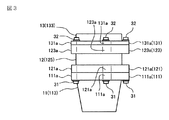
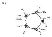
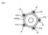
- 3 is a diagram schematically showing the appearance of the housing 10 (front housing 11, center housing 12, and rear housing 13) of the compressor 1, FIG.
- FIG. 4 is a diagram viewed from the rear
- FIG. 5 is a diagram viewed from the front. It is.
- the rear housing 13 has a joint end portion 131 and a body portion 133, and the rear side insertion portion 131 a in the rear housing 13 is more radial than the body portion 133. It is formed so as to protrude outward.
- the center housing 12 includes joining end portions 121 and 123 and a body portion 125, and the rear side screwing portion 123 a of the center housing 12 is formed so as to protrude outward in the radial direction from the body portion 125. .
- the fastening portion by the bolt 32 is outside the body portions 133 and 125 among the joining end portion 131 of the rear housing 13 and the joining end portion 123 on the rear end face 12b side of the center housing 12.
- the diameter of the pitch circle at the center of the bolt insertion hole 132 for the bolt 32 is set to be larger than the diameter of the body portion 133 of the rear housing 13.
- the front housing 11 has a joining end portion 111 and a body portion 113, and the front side insertion portion 111 a in the front housing 11 is radially outward from the body portion 113. It is formed to protrude.
- the front-side threaded portion 121 a of the center housing 12 is formed so as to protrude outward in the radial direction from the body portion 125 of the center housing 12. That is, in the present embodiment, only the fastening portion by the bolt 31 is outside the body portions 113 and 125 among the joint end portion 111 of the front housing 11 and the joint end portion 121 on the front end face 12a side of the center housing 12. It protrudes.
- the diameter of the pitch circle at the center of the bolt insertion hole 112 for the bolt 31 is set to be larger than the diameter of the body portion 113 of the front housing 11.
- the inner end surface 12b1 and the outer end surface 12b2 of the rear end surface 12b of the center housing 12 are formed flat on the same plane in a state where the load of the fastening force (pressing force) is released. .
- the rear end surface 12b of the center housing 12 is divided into the inner end surface 12b1 and the outer end surface 12b2, but in a state where the fastening force is not applied, it is a flat surface over the entire surface.
- the rear end surface 12b of the center housing 12 corresponds to “one of the joint surfaces” according to the invention. Therefore, the front end surface 13a of the rear housing 13 corresponds to “the other joint surface”.
- the outer end face 13a2 of the front end face 13a (the other joining face) of the rear housing 13 is in a state in which the load of the fastening force from the bolt 32 is released, as shown in FIGS.
- the outer end surface 13a2 is formed of, for example, a plane inclined with respect to the rear end surface (one joining surface) 12b of the center housing 12 in a state where the load of the fastening force is released.
- FIG. 1 a plane inclined with respect to the rear end surface (one joining surface) 12b of the center housing 12 in a state where the load of the fastening force is released.
- the inclination starting point of the outer end face 13a2 is inside the housing center side edge of the opening of the bolt insertion hole 132 of the rear side insertion part 131a (left side in the figure), that is, the drive shaft 42. It is set at a position close to the central axis side.
- the outer end surface 13a2 formed of an inclined plane is formed on the rear housing 13 side of the rear housing 13 and the center housing 12 that are joined to each other.
- the inclination starting point of this outer side end surface 13a2 is not restricted to this, For example, it is preferable that it is a position nearer to the inner side (left side in the figure) than the central axis of the bolt insertion hole 132. More specifically, as shown in FIG.
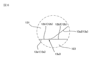
- FIG. 6 which is an enlarged view of a portion A shown in FIG. 2, a boundary portion 13a3 between the inner end surface 13a1 and the outer end surface 13a2 of the front end surface (joint surface) 13a of the rear housing 13 is shown. Is formed in an R shape in a state in which the load of the fastening force is released.
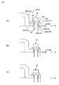
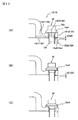
- FIG. 7 is a conceptual diagram for explaining a situation in which the rear side insertion portion 131a bends, and FIG.
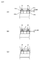
- FIGS. 8 is a conceptual diagram for explaining a change in surface pressure between adjacent bolts 32 at the time of bolt tightening.
- . 7A is a state before bolt tightening
- FIG. 7B is a state during bolt tightening
- FIG. 7C is the bolt tightening completed
- the entire front end surface (joint surface) 13a of the rear housing 13 is shown. That is, the entire inner end surface 13 a 1 and outer end surface 13 a 2 are in contact with the flat rear end surface 12 b of the center housing 12.
- FIGS. 8A, 8B, and 8C are views seen from the direction of the arrow X shown in FIGS. 7A, 7B, and 7C, respectively. .
- FIGS. 8A, 8B, and 8C are views seen from the direction of the arrow X shown in FIGS. 7A, 7B, and 7C, respectively. .
- an operator or the like joins both joint surfaces (the front end surface 13a and the rear end surface 12b) of the rear housing 13 and the center housing 12 together with bolts.
- Each bolt 32 is inserted through the insertion hole 132.
- Each bolt 32 is up to the point immediately before the head 32a is seated on the seat surface 13a4 formed on the end surface opposite to the outer end surface 13a2 formed of an inclined plane in the rear side insertion portion 131a by the operator or the like. Tightened. At this time, the inner end surface 13a1 of the rear housing 13 and the inner end surface 12b1 of the center housing 12 are in contact (joined).
- an initial gap G0 (G) is generated between the outer end surface 13a2 of the rear housing 13 and the outer end surface 12b2 of the center housing 12.
- the surface pressure P is not generated between both joint surfaces (the front end surface 13a and the rear end surface 12b).
- the surface pressure P in the region corresponding to the rear insertion portion 131a increases. Simultaneously with the increase in the surface pressure of the region corresponding to the rear side insertion portion 131a, as shown in FIG. 8B, the region corresponding to the adjacent bolts of both joint surfaces (the front end surface 13a and the rear end surface 12b). It has been experimentally confirmed that the surface pressure P also gradually increases and that the degree of nonuniformity of the surface pressure distribution in the circumferential direction of the inner end surfaces 13a1 and 12b1 gradually decreases.
- the surface pressure P in the region corresponding to the space between the adjacent bolts of the joint surfaces (front end surface 13a and rear end surface 12b) further increases, and the surface pressure distribution in the circumferential direction of the inner end surfaces 13a1 and 12b1.
- the degree of non-uniformity is reduced.
- the bolts 32 are tightened by an operator or the like until the outer end surface 13a2 of the rear side insertion portion 131a comes into contact with the outer end surface 12b2 of the center housing 12 and the gap G is eliminated.
- FIGS. 7C and 8C the fastening of the rear housing 13 and the center housing 12 with the bolts 32 is completed.
- a sufficient surface pressure is set in advance so as to be ensured between both the joining surfaces (the front end surface 13a and the rear end surface 12b).
- the diameter of the bolt insertion hole 132 is such that the neck portion of the bolt 32 is the inner wall surface of the bolt insertion hole 132 as shown in FIG. It is set not to touch.
- the rear housing 13 and the center housing 12 include a plurality of joint surfaces of the joint end portions 131 and 123 (specifically, both inner end surfaces 13a1 and 12b1) joined together. The bolts 32 are fastened to each other.
- the rear side insertion portion 131 a is set in a region corresponding to the outer end surface 13 a 2 in the joining end portion 131 of the rear housing 13.
- the rear side insertion portion 131a is A gap G is formed between the center housing 12 and the outer end surface 12b2.
- the rear side insertion portion 131a has elasticity that bends toward the center housing 12 side when the pressing force (fastening force) is applied.
- the joint surface (front end surface 13 a) of the rear housing 13 due to intrusion of salt water or the like between the rear housing 13 and the center housing 12 while suppressing an increase in manufacturing cost. And corrosion of the joint surface (rear end surface 12b) of the center housing 12, especially the joint surface between the bolts can be prevented or suppressed.
- the rear side insertion portion 131 a is formed so as to protrude outward in the radial direction from the body portion 133 of the rear housing 13. Thereby, since the rear side insertion part 131a can be bent easily, the structure which raises the surface pressure between adjacent volt
- the outer end surface 13a2 of the front end surface 13a (the other joint surface) of the rear housing 13 is the rear end surface of the center housing 12 as it goes radially outward in a state where the load of the fastening force is released. It is formed so as to be separated from 12b (one joint surface).
- the outer end surface 13a2 is configured to have a plane inclined with respect to the rear end surface 12b (one joining surface) in a state where the load of the fastening force is released. Thereby, the increase in the manufacturing cost for forming the outer side end surface 13a2 can be suppressed.
- the boundary portion 13a3 between the inner end surface 13a1 and the outer end surface 13a2 is formed in an R shape in a state where the load of the fastening force is released.
- boundary part 13a3 used as the fulcrum at the time of rear side insertion part 131a bending can be made into a smooth shape.
- the boundary portion 13a3 can be reliably brought into contact with the rear end surface 12b (one joining surface). Therefore, corrosion of the joint surface (front end surface 13a) of the rear housing 13 and the joint surface (rear end surface 12b) of the center housing 12 can be more reliably prevented.
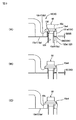
- FIG. 9 is an enlarged cross-sectional view showing a main part of a first modification of the compressor 1 and a conceptual diagram for explaining a situation where the rear side insertion portion 131a in the first modification is bent.
- the head portion 32a of the bolt 32 in the state where the fastening force is released (initial state), is opposite to the outer end surface 13a2 formed of an inclined plane in the rear side insertion portion 131a. It is in uniform contact with the seat surface 13a4 formed on the side end surface. However, the head portion 32a of the bolt 32 comes into a state where it comes into contact with the seating surface 13a4 as the rear side insertion portion 131a bends.
- the seat surface 13a4 when the bolt 32 is tightened and the rear side insertion portion 131a is bent, the seat surface 13a4 is substantially maintained in a state parallel to the outer end surface 13a2, while It approaches the end face 12b side. At this time, the inclination angle of the seat surface 13a4 with respect to the lower surface of the head portion 32a of the bolt 32 is reduced. 9C, the seating surface 13a4 is parallel to the outer end surface 13a2 and the rear end surface 12b. In this state, the lower surface of the head portion 32a of the bolt 32 is in contact with the seat surface 13a4 uniformly without contacting each other.
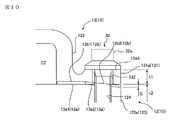
- FIG. 10 is an essential part enlarged cross-sectional view showing a second modification of the compressor 1.
- FIG. 11 is a conceptual diagram for explaining a situation where the rear side insertion portion 131a shown in FIG. 10 is bent.
- the inner end surface 12b1 and the outer end surface 12b2 of the joint surface (rear end surface 12b) of the center housing 12 are formed flat on the same plane in a state where the load of the fastening force is released.
- the present invention is not limited to this.
- the inner end surface 13a1 and the outer end surface 13a2 of the joining surface (front end surface 13a) of the rear housing 13 are in the same plane in a state in which the load of the fastening force is released. It is good also as a structure currently formed flatly.
- this modification 2 as shown in FIGS. 10 and 11, if the joint surface (rear end surface 12b) of the center housing 12 is formed so that the outer end surface 12b2 of the center housing 12 is inclined in the initial state. Good. That is, as shown in FIG. 10, the outer end surface 12b2 of the joint surface (rear end surface 12b) of the center housing 12 with the rear housing 13 is flatly joined to the rear housing 13 in a state where the load of the fastening force is released.
- the outer end surface (12b2 or 13a2) of the other joint surface (12b or 13a) has a diameter in a state in which the load of the fastening force is released. It can be set as the structure which consists of a plane inclined with respect to one joint surface (13a or 12b), so that it goes to the direction outer side. Moreover, in the said modification 2, similarly to the modification 1, the structure (modification 3) which eliminates the contact
- FIG. 12 is an enlarged cross-sectional view of a main part showing a third modification of the compressor 1 and a conceptual diagram for explaining a situation where the rear side insertion portion 131a in the third modification is bent.
- the seating surface 13a4 for contact with the head portion 32a of the bolt 32 is inclined with respect to the outer end surface 13a2 in the state where the load of the fastening force is released (initial state), and the fastening is performed.
- the inner end face 12b1 In a state where the gap G disappears due to force load (fastening completion state), the inner end face 12b1 is parallel. That is, in the initial state, the seating surface 13a4 is inclined to the opposite side of the inclined outer end surface 12b2, as shown in FIG.
- the seat surface 13a4 approaches the rear end surface 12b side. At this time, the inclination angle of the seat surface 13a4 with respect to the lower surface of the head portion 32a of the bolt 32 is reduced. And in the fastening completion state shown in FIG.12 (C), the seat surface 13a4 is parallel to the inner side end surface 12b1. In this state, the lower surface of the head portion 32a of the bolt 32 is in contact with the seat surface 13a4 uniformly without contacting each other.
- the outer end surfaces 13a2 and 12b2 are not limited to flat surfaces inclined in one direction, and may be curved surfaces in a state where the load of the fastening force is released.
- the rear housing 13 side is bent by the fastening force of the bolt 32.
- the present invention is not limited to this, and the center housing 12 side may be bent. That is, the “first housing member” according to the present invention is not limited to the rear housing 13 but may be the center housing 12. In this case, the rear housing 13 may be configured as a “second housing member” according to the present invention.
- the rear side insertion portion of the bolt 32 may be formed at the joint end portion 123 of the center housing 12, and the rear side screwing portion of the bolt 32 may be formed at the joint end portion 131 of the rear housing 13. Further, at the joint end portion 111 of the front housing 11 and the joint end portion 121 on the front end surface 12a side of the center housing 12, the joint end portion 131 of the rear housing 13 and the joint end portion 123 on the rear end surface 12b side of the center housing 12 are also provided.
- a similar configuration can be employed. That is, a bending structure for increasing the surface pressure P between adjacent bolts at the joining end portions 131 and 123 of the rear housing 13 and the center housing 12 may be adopted only on the rear side of the housing 10 or on the front side.
- the number of the bolts 31 and 32 can be set suitably. Further, the number of divisions and the divided parts of the housing 10 can be determined as appropriate, and the above-described bending structure may be appropriately adopted at the divided parts. Moreover, in this embodiment and each said modification, the joining end parts 111, 121, 123, 131 of each housing 11,12,13 are the insertion site
- the present invention is not limited to this, and all or a part of each of the joining end portions 111, 121, 123, 131 is formed into a flange shape over the whole without the corresponding portion between adjacent bolts being thinned. It may be formed. Even in this case, the rear side insertion part 131a, the front side insertion part 111a, etc. can be bent, and the fixed effect which raises the surface pressure P between adjacent volt
- the bolts 32 and 31 with a head were mentioned and demonstrated as an example of a fastening member, a fastening member is not restricted to this,
- the bolts 32 and 31 with a head It may be made of a nut, or may be made of a stud bolt and a nut without a head.
- this invention is not limited to the above-mentioned embodiment and modification, Further deformation
- transformation and change are possible based on the technical idea of this invention. It is.
Landscapes
- Engineering & Computer Science (AREA)
- Mechanical Engineering (AREA)
- General Engineering & Computer Science (AREA)
- Compressor (AREA)
- Applications Or Details Of Rotary Compressors (AREA)
- Rotary Pumps (AREA)
Abstract
Compresseur comprenant un boîtier formé d'une pluralité d'éléments de boîtier et empêchant des surfaces de jonction des éléments de boîtier de se corroder en raison de l'eau salée ou autre tout en supprimant une augmentation du coût de fabrication. Dans un boîtier 10 d'un compresseur 1, un boîtier central 12 et un boîtier arrière 13 sont fixés par une pluralité de boulons 32 dans l'état où les surfaces de jonction 12b, 13a sont jointes l'une à l'autre. Une partie d'introduction côté arrière 131a du boulon 32 est disposée dans une région, dans une extrémité de jonction 131 du boîtier arrière 13, correspondant à une surface d'extrémité extérieure 13a2. Dans l'état où une force de fixation du boulon 32 n'est pas appliquée à la partie d'introduction côté arrière 131a, il y a un espace G entre la partie d'introduction côté arrière 131a et la surface d'extrémité extérieure 13a2 du boîtier central 12. La partie d'introduction côté arrière présente une élasticité qui permet une courbure vers le boîtier central 12 lorsque la force de fixation est appliquée.
Applications Claiming Priority (2)
| Application Number | Priority Date | Filing Date | Title |
|---|---|---|---|
| JP2016-170186 | 2016-08-31 | ||
| JP2016170186A JP2018035757A (ja) | 2016-08-31 | 2016-08-31 | 圧縮機 |
Publications (1)
| Publication Number | Publication Date |
|---|---|
| WO2018043151A1 true WO2018043151A1 (fr) | 2018-03-08 |
Family
ID=61300734
Family Applications (1)
| Application Number | Title | Priority Date | Filing Date |
|---|---|---|---|
| PCT/JP2017/029578 Ceased WO2018043151A1 (fr) | 2016-08-31 | 2017-08-10 | Compresseur |
Country Status (2)
| Country | Link |
|---|---|
| JP (1) | JP2018035757A (fr) |
| WO (1) | WO2018043151A1 (fr) |
Citations (6)
| Publication number | Priority date | Publication date | Assignee | Title |
|---|---|---|---|---|
| JPS5283014U (fr) * | 1975-12-19 | 1977-06-21 | ||
| JPS63174598U (fr) * | 1987-01-22 | 1988-11-11 | ||
| JPH08219022A (ja) * | 1995-02-13 | 1996-08-27 | Sanwa Seiki Co Ltd | エアコンプレッサ |
| JP2004293453A (ja) * | 2003-03-27 | 2004-10-21 | Keihin Corp | スクロール型圧縮機 |
| JP2013204446A (ja) * | 2012-03-27 | 2013-10-07 | Toyota Industries Corp | 圧縮機 |
| JP2015121124A (ja) * | 2013-12-20 | 2015-07-02 | カルソニックカンセイ株式会社 | 気体圧縮機 |
-
2016
- 2016-08-31 JP JP2016170186A patent/JP2018035757A/ja active Pending
-
2017
- 2017-08-10 WO PCT/JP2017/029578 patent/WO2018043151A1/fr not_active Ceased
Patent Citations (6)
| Publication number | Priority date | Publication date | Assignee | Title |
|---|---|---|---|---|
| JPS5283014U (fr) * | 1975-12-19 | 1977-06-21 | ||
| JPS63174598U (fr) * | 1987-01-22 | 1988-11-11 | ||
| JPH08219022A (ja) * | 1995-02-13 | 1996-08-27 | Sanwa Seiki Co Ltd | エアコンプレッサ |
| JP2004293453A (ja) * | 2003-03-27 | 2004-10-21 | Keihin Corp | スクロール型圧縮機 |
| JP2013204446A (ja) * | 2012-03-27 | 2013-10-07 | Toyota Industries Corp | 圧縮機 |
| JP2015121124A (ja) * | 2013-12-20 | 2015-07-02 | カルソニックカンセイ株式会社 | 気体圧縮機 |
Also Published As
| Publication number | Publication date |
|---|---|
| JP2018035757A (ja) | 2018-03-08 |
Similar Documents
| Publication | Publication Date | Title |
|---|---|---|
| US20170146014A1 (en) | Scroll compressor | |
| US9366253B2 (en) | Scroll compressor and processing method of scroll including a projection on a tip seal and a hole in a tip seal groove | |
| WO2017013987A1 (fr) | Compresseur à volute | |
| US7147444B2 (en) | Assembling mechanism of discharge pipe for hermetic compressor and method thereof | |
| US20190120229A1 (en) | Scroll fluid machine and method for producing same | |
| JP2018035757A (ja) | 圧縮機 | |
| US9771952B2 (en) | Screw compressor | |
| JP6305833B2 (ja) | スクロール圧縮機 | |
| JP6879667B2 (ja) | 分割式ハウジングの位置決め構造、これを備えたスクロール圧縮機 | |
| JP6727300B2 (ja) | ロータリー圧縮機 | |
| KR102794406B1 (ko) | 압축기 | |
| CN111954969B (zh) | 用于电动机器的定子组件 | |
| JP3135470B2 (ja) | 往復ピストン式圧縮機 | |
| US8419397B2 (en) | Screw compressor | |
| JP6909704B2 (ja) | 流体制御弁 | |
| JP4400689B2 (ja) | スクリュー圧縮機 | |
| CN116745522A (zh) | 流体机械 | |
| KR102330158B1 (ko) | 스크롤 압축기 | |
| US20100172774A1 (en) | Compressor | |
| WO2019073602A1 (fr) | Pompe à engrenages ou moteur | |
| JP6133234B2 (ja) | オイルポンプの取り付け構造 | |
| JP6425487B2 (ja) | スクロール型流体機械 | |
| JP2025080291A (ja) | スクロール圧縮機 | |
| KR101230732B1 (ko) | 수평형 스크롤 압축기 | |
| JP5878939B2 (ja) | 圧縮機 |
Legal Events
| Date | Code | Title | Description |
|---|---|---|---|
| 121 | Ep: the epo has been informed by wipo that ep was designated in this application |
Ref document number: 17846159 Country of ref document: EP Kind code of ref document: A1 |
|
| NENP | Non-entry into the national phase |
Ref country code: DE |
|
| 122 | Ep: pct application non-entry in european phase |
Ref document number: 17846159 Country of ref document: EP Kind code of ref document: A1 |